EP0788624B1 - Procede d'analyse d'une valeur mesuree et analyseur de valeur mesuree pour la mise en oeuvre de ce procede - Google Patents
Procede d'analyse d'une valeur mesuree et analyseur de valeur mesuree pour la mise en oeuvre de ce procede Download PDFInfo
- Publication number
- EP0788624B1 EP0788624B1 EP95934597A EP95934597A EP0788624B1 EP 0788624 B1 EP0788624 B1 EP 0788624B1 EP 95934597 A EP95934597 A EP 95934597A EP 95934597 A EP95934597 A EP 95934597A EP 0788624 B1 EP0788624 B1 EP 0788624B1
- Authority
- EP
- European Patent Office
- Prior art keywords
- measured value
- measurement
- measurement value
- rules
- comparison
- Prior art date
- Legal status (The legal status is an assumption and is not a legal conclusion. Google has not performed a legal analysis and makes no representation as to the accuracy of the status listed.)
- Expired - Lifetime
Links
Images
Classifications
-
- G—PHYSICS
- G05—CONTROLLING; REGULATING
- G05B—CONTROL OR REGULATING SYSTEMS IN GENERAL; FUNCTIONAL ELEMENTS OF SUCH SYSTEMS; MONITORING OR TESTING ARRANGEMENTS FOR SUCH SYSTEMS OR ELEMENTS
- G05B23/00—Testing or monitoring of control systems or parts thereof
- G05B23/02—Electric testing or monitoring
- G05B23/0205—Electric testing or monitoring by means of a monitoring system capable of detecting and responding to faults
- G05B23/0218—Electric testing or monitoring by means of a monitoring system capable of detecting and responding to faults characterised by the fault detection method dealing with either existing or incipient faults
- G05B23/0221—Preprocessing measurements, e.g. data collection rate adjustment; Standardization of measurements; Time series or signal analysis, e.g. frequency analysis or wavelets; Trustworthiness of measurements; Indexes therefor; Measurements using easily measured parameters to estimate parameters difficult to measure; Virtual sensor creation; De-noising; Sensor fusion; Unconventional preprocessing inherently present in specific fault detection methods like PCA-based methods
-
- G—PHYSICS
- G01—MEASURING; TESTING
- G01D—MEASURING NOT SPECIALLY ADAPTED FOR A SPECIFIC VARIABLE; ARRANGEMENTS FOR MEASURING TWO OR MORE VARIABLES NOT COVERED IN A SINGLE OTHER SUBCLASS; TARIFF METERING APPARATUS; MEASURING OR TESTING NOT OTHERWISE PROVIDED FOR
- G01D18/00—Testing or calibrating apparatus or arrangements provided for in groups G01D1/00 - G01D15/00
-
- G—PHYSICS
- G01—MEASURING; TESTING
- G01D—MEASURING NOT SPECIALLY ADAPTED FOR A SPECIFIC VARIABLE; ARRANGEMENTS FOR MEASURING TWO OR MORE VARIABLES NOT COVERED IN A SINGLE OTHER SUBCLASS; TARIFF METERING APPARATUS; MEASURING OR TESTING NOT OTHERWISE PROVIDED FOR
- G01D3/00—Indicating or recording apparatus with provision for the special purposes referred to in the subgroups
- G01D3/08—Indicating or recording apparatus with provision for the special purposes referred to in the subgroups with provision for safeguarding the apparatus, e.g. against abnormal operation, against breakdown
-
- G—PHYSICS
- G05—CONTROLLING; REGULATING
- G05B—CONTROL OR REGULATING SYSTEMS IN GENERAL; FUNCTIONAL ELEMENTS OF SUCH SYSTEMS; MONITORING OR TESTING ARRANGEMENTS FOR SUCH SYSTEMS OR ELEMENTS
- G05B9/00—Safety arrangements
- G05B9/02—Safety arrangements electric
Definitions
- the invention relates to a method for analyzing a Measured value in a plant process from a measuring system determined and at a first comparison point using for the measuring system specific parameters checked for plausibility becomes. It also relates to a measured value analyzer to carry out the procedure.
- the physical state or the measurand is usually detected by a sensor within a measuring system and along a measuring section by means of a converter into the measuring signal reshaped, optionally using an analog-digital converter converted measurement signal for plausibility is checked.
- This plausibility check is usually carried out at a comparison point based on for the measurement system specific parameters. These in turn are from known Sizes of the sensor and the converter as well as the analog-digital converter and the measuring section of the measuring system, e.g. Temperature range, Signal or measuring range, tolerance range, signal-to-noise ratio and / or environmental influences, and from a Monitoring of the power supply of the measuring system derived.
- the invention is therefore based on the object of a method for analysis or processing of a measured value, with which system-related errors can be selected and evaluated. This is said to be suitable for carrying out the method Measured value analyzer achieved with simple means will.
- this object is achieved according to the invention solved in that the measured value at a second comparison point based on rules characteristic of the plant process with regard to its consistency regardless of the measured value determined measurement parameters is checked, depending on Result of this review is a confidence factor for the Measured value is determined.
- the invention is based on the consideration that after Plausibility check based on one of the parameters of the measuring system created pattern of the sensor and the measuring section no reliable statement regarding the truth of the measured value determined can be taken. Rather, the result of this plausibility check is after Pass the first comparison point again on the Basis of further or others, via the plausibility check criteria based on the measurement system pattern to check. If this check is carried out using a Recheck with the determined measured value Measurement parameters, which are also preferably based on this method can be analyzed or checked, a statement about the safety or probability of error of the measured value is determined will.
- the measured value analyzer with a first comparison module
- the one with a parameter memory for a measured value determining measuring system is connected, the said Object achieved according to the invention by a second comparison module, the one with the first comparison block and on the other hand is connected to a data store, in which at least also those determined independently of the measured value Measurement parameters are stored, from which the process engineering characterizing the plant process Regulate a reference or target value - and thus also a weighting factor - Can be derived for the measured value
- the second Comparison module with an evaluation module for determination a confidence factor for the measured value.
- the weighting or confidence factor is preferably in one evaluation module connected to the second comparison module determined based on expert knowledge and then before or during further processing of measured values assigned to the measured value.
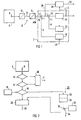
- FIG. 1 shows a basic circuit diagram of the measured value analyzer 2, the one via a measuring system 4 in a only indicated schematically Plant process 6 detected measured value MW is supplied.
- the measuring system 4 comprises a measuring sensor 8 which determines a specific one physical state of the plant process 6, e.g. a Temperature. It also includes along a measurement path 10 a converter 12 for generating a measurement signal and an analog / digital converter 14.
- a measuring sensor 8 determines a specific one physical state of the plant process 6, e.g. a Temperature. It also includes along a measurement path 10 a converter 12 for generating a measurement signal and an analog / digital converter 14.
- the plant process 6 is it e.g. process engineering in a turbo set realized conversion of thermal energy into electrical Energy.
- the measured value analyzer 2 has a first comparison module 16 and a parameter memory 18 connected to the latter for the measuring system 4.
- the measured value analyzer 2 also has a second comparison module 20, which with the first Comparison block 16 and with a data memory 22 for independent measurement parameters determined from the measured value MW and with a Evaluation module 24 is connected.
- a branch 26 provided in a block 28 for processing measured values leads.
- the output from the measuring system 4 to the measured value analyzer 2 Measured value MW is generated from the parameter memory using characteristic variables K. 18 checked at the first comparison point 16 for plausibility.
- This plausibility check is based on known Sizes of measuring system 4, i.e. for example using Manufacturer information regarding the sensor 8 and the converter 12 and the analog / digital converter 14. From this manufacturer's information and from characteristics derived from basic measurements as well as from environmental influences or conditions, such as air humidity and temperature, the parameters K become algorithmic determined and in the form of a sample of the measuring system 4 stored in the parameter memory 18. It also creates a pattern the measuring section 10 created and also in the parameter memory 18 saved. Entering these properties of the measuring system 4 in the parameter memory 18 is by the Arrow 29 indicated.
- a condition check is first carried out by means of the measured value analyzer 2 of the transducer 12 and the analog / digital converter 14.
- the transmitter 12 and / or the analog / digital converter 14 fails, takes place via a Message block 30 a message and, if necessary - as by the arrow 31 indicated - a blanking of measured values.
- the measured value MW with the compared to the parameters K derived patterns. Based on the Pattern is first recognized whether the measured value MW is plausible is, i.e. whether he between a given top and Lower limit.
- the measured value analyzer 2 of the transducer 12 and the analog / digital converter 14 fails, takes place via a Message block 30 a message and, if necessary - as by the arrow 31 indicated - a blanking of measured values.
- the measured value MW with the compared to the parameters K derived patterns. Based on the Pattern is first recognized whether the measured value MW is plausible is, i.e. whether he between a given top and Lower limit.
- the Gradient of the measured value MW compared to the possible temporal Change in the measured physical state of the plant process 6 is plausible.
- change e.g. the measured value MW faster than the corresponding one physical state can change, the measured value MW falls or the measurement signal from the pattern and there is a Error message.
- An error message occurs e.g. even if in a so-called life-zero monitoring of the measuring system 4 Measured value MW shifted from the actual zero point Falls below the lower limit of the measuring system 4.
- the measured value MW is recognized as not plausible. Otherwise, a measured value MW that is recognized as plausible is exceeded the branch 26 (FIG. 1) of the further measured value processing 28 fed.
- the pattern recognition makes it plausible Measured value MW fed to the second comparison point 20 and there with characteristic for the plant process 6, process engineering R compared rules.
- This is in the data store 22 deposited a set of rules, the rules of which are based on Expert knowledge determined independently of the measured value MW Measurement parameters are set up.
- characteristic rules R becomes the measured value MW initially with regard to its consistency with the independent measurement parameters determined from the measured value MW from the plant process 6 checked.
- pattern recognition requires that a particular Temperature value must be between 20 ° C and 50 ° C, and there the corresponding measured value MW e.g. a temperature T of 30 ° C this measured value MW passes the first comparison point 16.
- the Measured value MW has been measured on a pipe that is hot Steam with a steam pressure p of e.g. 10 bar and a flow rate v of e.g. 3 m / s and a temperature T ' from e.g. 50 ° C is flowed through as a measurement parameter, so takes place based on the rules R according to a predetermined algorithm Derivation or reproduction of the measured value MW from these measurement parameters p, v, T '.
- a based on these measurement parameters p, v, T ' derived reference or setpoint is at the second comparison point 20 compared with the actually recorded measured value MW. If the measured value MW deviates from this reference value, then the measured value is evaluated in the evaluation module 24 MW. In doing so, in a knowledge base 32 ( Figure 2) stored expert knowledge a confidence factor C determined for weighting the measured value MW. The confidence factor C is fed to block 28 for processing measured values and together with the measured value MW - as indicated by arrow 33 - For example, supplied to a diagnostic system. The diagnostic system is the measured value MW with a statement about the safety or the degree of error of the measured value MW, with a confidence factor C of e.g.
- measured values MW can advantageously systematic errors of the measuring system 4 are also recognized, in particular, slight drift movements of the detected Measured value MW recognized over a certain measuring period will.
- the one degree of error of the measured value is MW a particularly high reflecting weighting of the measured value MW Security when analyzing and diagnosing what is to be monitored Process 6 guaranteed.
Landscapes
- Physics & Mathematics (AREA)
- General Physics & Mathematics (AREA)
- Engineering & Computer Science (AREA)
- Automation & Control Theory (AREA)
- Testing Or Calibration Of Command Recording Devices (AREA)
Claims (3)
- Procédé pour l'analyse d'une valeur mesurée (MW) qui est déterminée dans un processus industriel (6) par un système de mesure (4) et dont la vraisemblance est testée en un premier point de comparaison (16) à l'aide de grandeurs caractéristiques (K) spécifiques au système de mesure (4),
caractérisé par le fait que l'on teste la valeur mesurée (MW) en un deuxième point de comparaison (20) à l'aide de règles (R) caractéristiques du processus industriel (6) du point de vue de sa cohérence avec des paramètres de mesure déterminés indépendamment de la valeur mesurée (MW), un facteur de confiance (C) étant déterminé pour la valeur mesurée (MW) en fonction du résultat de ce test. - Procédé selon la revendication 1,
caractérisé par le fait que l'on actualise avec la valeur mesurée (MW) les règles (R) caractéristiques du processus industriel (6). - Analyseur de valeur mesurée, notamment pour la mise en oeuvre du procédé selon l'une des revendications 1 ou 2, comportant un premier composant de comparaison (16) qui est relié à une mémoire de grandeurs caractéristiques (18) pour un système de mesure (4) déterminant la valeur mesurée (MW),
caractérisé par un deuxième composant de comparaison (20) qui est relié au premier composant de comparaison (16) et à une mémoire de données (22) destinée à des paramètres de mesure qui sont déterminés indépendamment de la valeur mesurée (MW) et à partir desquels une valeur de consigne pour la valeur mesurée (MW) peut être déduite au moyen de règles (R) caractérisant le processus industriel (6), le deuxième composant de comparaison (20) étant relié à un composant d'estimation (24) pour la détermination d'un facteur de confiance (C) pour la valeur mesurée (MW).
Applications Claiming Priority (3)
| Application Number | Priority Date | Filing Date | Title |
|---|---|---|---|
| DE4438300 | 1994-10-26 | ||
| DE4438300 | 1994-10-26 | ||
| PCT/DE1995/001420 WO1996013764A1 (fr) | 1994-10-26 | 1995-10-13 | Procede d'analyse d'une valeur mesuree et analyseur de valeur mesuree pour la mise en ×uvre de ce procede |
Publications (2)
| Publication Number | Publication Date |
|---|---|
| EP0788624A1 EP0788624A1 (fr) | 1997-08-13 |
| EP0788624B1 true EP0788624B1 (fr) | 1998-08-26 |
Family
ID=6531781
Family Applications (1)
| Application Number | Title | Priority Date | Filing Date |
|---|---|---|---|
| EP95934597A Expired - Lifetime EP0788624B1 (fr) | 1994-10-26 | 1995-10-13 | Procede d'analyse d'une valeur mesuree et analyseur de valeur mesuree pour la mise en oeuvre de ce procede |
Country Status (9)
| Country | Link |
|---|---|
| US (1) | US5835886A (fr) |
| EP (1) | EP0788624B1 (fr) |
| KR (1) | KR100485025B1 (fr) |
| CN (1) | CN1103946C (fr) |
| AU (1) | AU3697295A (fr) |
| BR (1) | BR9509446A (fr) |
| DE (1) | DE59503378D1 (fr) |
| HK (1) | HK1001793A1 (fr) |
| WO (1) | WO1996013764A1 (fr) |
Cited By (1)
| Publication number | Priority date | Publication date | Assignee | Title |
|---|---|---|---|---|
| DE102021210010A1 (de) | 2021-09-10 | 2023-03-16 | Robert Bosch Gesellschaft mit beschränkter Haftung | Sensorvorrichtung und Messverfahren |
Families Citing this family (21)
| Publication number | Priority date | Publication date | Assignee | Title |
|---|---|---|---|---|
| FR2755945B1 (fr) * | 1996-11-19 | 1999-01-15 | Eurocopter France | Indicateur de pilotage pour aeronef |
| DE10007644A1 (de) * | 2000-02-19 | 2001-08-23 | Hella Kg Hueck & Co | Verfahren zur Fehlererkennung bei PWM-Signalen |
| US6553324B2 (en) | 2000-07-18 | 2003-04-22 | Eads Deutschland Gmbh | Method and device for detection of a defect in a sensor system |
| DE10065920B4 (de) * | 2000-07-18 | 2006-07-06 | Eads Deutschland Gmbh | Verfahren und Einrichtung zur Erkennung eines Defekts in einem Sensorsystem |
| US6944759B1 (en) * | 2000-09-29 | 2005-09-13 | Hewlett-Packard Development Company, L.P. | Automatic system configuration management |
| US6738931B1 (en) | 2000-11-03 | 2004-05-18 | General Electric Company | Reliability assessment method, apparatus and system for quality control |
| US6556939B1 (en) * | 2000-11-22 | 2003-04-29 | Smartsignal Corporation | Inferential signal generator for instrumented equipment and processes |
| JPWO2002057860A1 (ja) * | 2001-01-22 | 2004-05-27 | 東京エレクトロン株式会社 | 機器の生産性向上システム及びその方法 |
| AT4497U3 (de) * | 2001-03-28 | 2001-12-27 | Avl List Gmbh | Verfahren zur analyse und bewertung von messwerten eines offenen prüfsystems |
| WO2006129235A1 (fr) * | 2005-06-01 | 2006-12-07 | Koninklijke Philips Electronics N.V. | Procede et dispositif pour verifier des donnees detectees |
| US8173071B2 (en) * | 2006-08-29 | 2012-05-08 | International Business Machines Corporation | Micro-fluidic test apparatus and method |
| US7696866B2 (en) * | 2007-06-28 | 2010-04-13 | Microsoft Corporation | Learning and reasoning about the context-sensitive reliability of sensors |
| EP2221696A1 (fr) * | 2009-02-12 | 2010-08-25 | Siemens Aktiengesellschaft | Procédé et dispositif de contrôle d'un programme de commande d'une installation industrielle |
| US9158302B2 (en) * | 2012-05-04 | 2015-10-13 | Siemens Energy, Inc. | System and method for detecting electric power plant equipment overheating with real-time plural parallel detection and analysis parameters |
| RU2537801C2 (ru) * | 2013-01-29 | 2015-01-10 | Открытое акционерное общество "Ракетно-космический центр "Прогресс" (ОАО "РКЦ "Прогресс") | Способ обслуживания сложных технических систем и автоматизированная система контроля для его осуществления (варианты) |
| SE536922C2 (sv) * | 2013-02-19 | 2014-10-28 | Basim Al-Najjar | En metod och en apparat för att prediktera tillståndet hos en maskin eller en komponent hos maskinen |
| EP3016352B1 (fr) * | 2014-11-03 | 2019-02-06 | Fujitsu Limited | Procédé de gestion de réseau de capteurs |
| DE102014223251B3 (de) * | 2014-11-14 | 2016-03-24 | Db Netz Ag | Verfahren und Vorrichtung zur Erfassung, Auswertung und Darstellung von Messwerten von Motoren elektrischer Antriebe |
| DE102015118008A1 (de) * | 2015-10-22 | 2017-04-27 | Dr. Ing. H.C. F. Porsche Aktiengesellschaft | Verfahren zur Analyse und Bewertung von Messwerten eines Prüfsystems |
| EP3653428A1 (fr) * | 2018-11-19 | 2020-05-20 | B&R Industrial Automation GmbH | Procédé de surveillance sûre du fonctionnement d'un moteur linéaire à stator long |
| EP3764181A1 (fr) * | 2019-07-09 | 2021-01-13 | Siemens Aktiengesellschaft | Vérification automatique d'un parametre d'appareil |
Family Cites Families (14)
| Publication number | Priority date | Publication date | Assignee | Title |
|---|---|---|---|---|
| DE3314181A1 (de) * | 1983-04-19 | 1984-10-25 | Kraftwerk Union AG, 4330 Mülheim | Verfahren zur ueberwachung der ermuedung von bauteilen, z.b. in kernkraftwerken |
| US4649515A (en) * | 1984-04-30 | 1987-03-10 | Westinghouse Electric Corp. | Methods and apparatus for system fault diagnosis and control |
| US4644479A (en) * | 1984-07-31 | 1987-02-17 | Westinghouse Electric Corp. | Diagnostic apparatus |
| US4642782A (en) * | 1984-07-31 | 1987-02-10 | Westinghouse Electric Corp. | Rule based diagnostic system with dynamic alteration capability |
| DE3435465A1 (de) * | 1984-08-03 | 1986-02-13 | Robert Bosch Gmbh, 7000 Stuttgart | Verfahren und vorrichtung zur eigendiagnose von stellgliedern |
| DE3538908A1 (de) * | 1985-11-02 | 1987-05-21 | Holzapfel Wolfgang Prof Dr Ing | Bordautonomes ortungssystem fuer positionsermittlung und kollisionsschutz von roboter- und flurfoerderfahrzeugen |
| KR890007306A (ko) * | 1987-10-30 | 1989-06-19 | 제트.엘.더머 | 온라인 밸브 진단 감시 시스템 |
| US5132920A (en) * | 1988-02-16 | 1992-07-21 | Westinghouse Electric Corp. | Automated system to prioritize repair of plant equipment |
| JPH02147968A (ja) * | 1988-11-30 | 1990-06-06 | Fuji Heavy Ind Ltd | 電気回路の異常検出装置 |
| DE3921286A1 (de) * | 1989-06-29 | 1991-01-03 | Linde Ag | Verfahren zum sicheren elektronischen steuern eines prozesses |
| JP3224226B2 (ja) * | 1989-09-22 | 2001-10-29 | 株式会社リコー | 故障診断エキスパートシステム |
| US5089978A (en) * | 1990-02-09 | 1992-02-18 | Westinghouse Electric Corp. | Automatic plant state diagnosis system including a display selection system for selecting displays responsive to the diagnosis |
| JPH04198729A (ja) * | 1990-11-29 | 1992-07-20 | Toshiba Corp | 診断用エキスパートシステム |
| US5293323A (en) * | 1991-10-24 | 1994-03-08 | General Electric Company | Method for fault diagnosis by assessment of confidence measure |
-
1995
- 1995-10-13 CN CN95195736A patent/CN1103946C/zh not_active Expired - Fee Related
- 1995-10-13 DE DE59503378T patent/DE59503378D1/de not_active Expired - Lifetime
- 1995-10-13 WO PCT/DE1995/001420 patent/WO1996013764A1/fr not_active Application Discontinuation
- 1995-10-13 AU AU36972/95A patent/AU3697295A/en not_active Abandoned
- 1995-10-13 KR KR1019970702718A patent/KR100485025B1/ko not_active IP Right Cessation
- 1995-10-13 BR BR9509446A patent/BR9509446A/pt not_active IP Right Cessation
- 1995-10-13 EP EP95934597A patent/EP0788624B1/fr not_active Expired - Lifetime
-
1997
- 1997-04-28 US US08/847,890 patent/US5835886A/en not_active Expired - Lifetime
-
1998
- 1998-01-06 HK HK98100089A patent/HK1001793A1/xx not_active IP Right Cessation
Cited By (1)
| Publication number | Priority date | Publication date | Assignee | Title |
|---|---|---|---|---|
| DE102021210010A1 (de) | 2021-09-10 | 2023-03-16 | Robert Bosch Gesellschaft mit beschränkter Haftung | Sensorvorrichtung und Messverfahren |
Also Published As
| Publication number | Publication date |
|---|---|
| HK1001793A1 (en) | 1998-07-10 |
| KR970707473A (ko) | 1997-12-01 |
| EP0788624A1 (fr) | 1997-08-13 |
| WO1996013764A1 (fr) | 1996-05-09 |
| CN1103946C (zh) | 2003-03-26 |
| US5835886A (en) | 1998-11-10 |
| BR9509446A (pt) | 1997-12-23 |
| CN1161091A (zh) | 1997-10-01 |
| AU3697295A (en) | 1996-05-23 |
| KR100485025B1 (ko) | 2005-06-16 |
| DE59503378D1 (de) | 1998-10-01 |
Similar Documents
| Publication | Publication Date | Title |
|---|---|---|
| EP0788624B1 (fr) | Procede d'analyse d'une valeur mesuree et analyseur de valeur mesuree pour la mise en oeuvre de ce procede | |
| DE3047310C2 (de) | Betriebsüberwachungseinrichtung für Dampfkraftwerke | |
| DE3390539C2 (de) | Verfahren zum Betreiben eines adaptiv gesteuerten technischen Prozesses | |
| EP1241438B1 (fr) | Dispositif de mesure d'angle | |
| EP2246984B1 (fr) | Appareil de diagnostic destinée au contrôle d'un appareil de conversion analogique-numérique | |
| EP0800059B2 (fr) | Procédé de transfert de données dans un dispositif de mesure de position | |
| EP3279756B1 (fr) | Dispositif de diagnostic et procédé de surveillance du fonctionnement d'une installation technique | |
| EP3631593B1 (fr) | Dispositif de surveillance et procédé de surveillance d'un système | |
| DE60210157T2 (de) | Gerät zur Abschätzung von Brennkammerdruckschwankungen, Anlage und Gasturbinenanlage | |
| DE10359988A1 (de) | Messeinrichtung, insbesondere Temperaturmessumformer | |
| DE10050392A1 (de) | Positionsmesseinrichtung und Verfahren zum Betrieb einer Positionsmesseinrichtung | |
| EP3282399A1 (fr) | Procede de reconnaissance ameliore d'anomalies de processus d'une installation technique et systeme de diagnostic correspondant | |
| DE102008057474B4 (de) | Meßumformer | |
| DE102018217118B4 (de) | Verfahren zum Erstellen einer Fehlerdiagnose eines Antriebsstrangs eines elektrisch betriebenen Kraftfahrzeugs und Kraftfahrzeug | |
| EP1677082B1 (fr) | Procédé de réalisation d'un test de fonctionnement d'un dispositif de mesure de position et dispositif de mesure de position destiné à la réalisation de ce procédé | |
| DE102006024742A1 (de) | Messumformer | |
| DE3920516A1 (de) | Steuersystem fuer industrielle anlagen | |
| DE102011103248A1 (de) | Sensoreinrichtung und Verfahren zur Überwachung einer Sensoreinrichtung | |
| DE10318171A1 (de) | Verfahren zur funktionsüberwachten Bestimmung einer Messgröße sowie ein in diesem Verfahren verwendbarer Messwertaufnehmer und Verwendung desselben | |
| DE112020003659T5 (de) | Verfahren zur diagnose von anomalien, vorrichtung zur diagnose von anomalienund programm zur diagnose von anomalien | |
| EP1302753B1 (fr) | Méthode de surveillance pour un détecteur de position | |
| DE10114206A1 (de) | Überwachung und Steuerung von Prozessen unter Verwendung selbstüberprüfender Sensoren | |
| DE102014009354A1 (de) | Verfahren und Vorrichtung zur Fehleranalyse einer Messeinrichtung | |
| DE102017204400A1 (de) | Verfahren zum Betrieb eines Sensors und Verfahren und Vorrichtung zum Analysieren von Daten eines Sensors | |
| DE3119045C2 (de) | Verfahren und Anordnung zur Feststellung und Meldung von Kühlungsstörungen in einem Brennelement eines Reaktorkerns |
Legal Events
| Date | Code | Title | Description |
|---|---|---|---|
| PUAI | Public reference made under article 153(3) epc to a published international application that has entered the european phase |
Free format text: ORIGINAL CODE: 0009012 |
|
| 17P | Request for examination filed |
Effective date: 19970218 |
|
| AK | Designated contracting states |
Kind code of ref document: A1 Designated state(s): CH DE FR GB IT LI NL SE |
|
| GRAG | Despatch of communication of intention to grant |
Free format text: ORIGINAL CODE: EPIDOS AGRA |
|
| GRAG | Despatch of communication of intention to grant |
Free format text: ORIGINAL CODE: EPIDOS AGRA |
|
| GRAG | Despatch of communication of intention to grant |
Free format text: ORIGINAL CODE: EPIDOS AGRA |
|
| GRAH | Despatch of communication of intention to grant a patent |
Free format text: ORIGINAL CODE: EPIDOS IGRA |
|
| 17Q | First examination report despatched |
Effective date: 19970115 |
|
| GRAH | Despatch of communication of intention to grant a patent |
Free format text: ORIGINAL CODE: EPIDOS IGRA |
|
| GRAA | (expected) grant |
Free format text: ORIGINAL CODE: 0009210 |
|
| AK | Designated contracting states |
Kind code of ref document: B1 Designated state(s): CH DE FR GB IT LI NL SE |
|
| REG | Reference to a national code |
Ref country code: CH Ref legal event code: EP |
|
| REG | Reference to a national code |
Ref country code: CH Ref legal event code: NV Representative=s name: SIEMENS SCHWEIZ AG |
|
| REF | Corresponds to: |
Ref document number: 59503378 Country of ref document: DE Date of ref document: 19981001 |
|
| ET | Fr: translation filed | ||
| GBT | Gb: translation of ep patent filed (gb section 77(6)(a)/1977) |
Effective date: 19981027 |
|
| PLBE | No opposition filed within time limit |
Free format text: ORIGINAL CODE: 0009261 |
|
| STAA | Information on the status of an ep patent application or granted ep patent |
Free format text: STATUS: NO OPPOSITION FILED WITHIN TIME LIMIT |
|
| 26N | No opposition filed | ||
| REG | Reference to a national code |
Ref country code: GB Ref legal event code: IF02 |
|
| REG | Reference to a national code |
Ref country code: CH Ref legal event code: PCAR Free format text: SIEMENS SCHWEIZ AG;INTELLECTUAL PROPERTY FREILAGERSTRASSE 40;8047 ZUERICH (CH) |
|
| PGFP | Annual fee paid to national office [announced via postgrant information from national office to epo] |
Ref country code: CH Payment date: 20120110 Year of fee payment: 17 |
|
| PGFP | Annual fee paid to national office [announced via postgrant information from national office to epo] |
Ref country code: DE Payment date: 20111219 Year of fee payment: 17 |
|
| PGFP | Annual fee paid to national office [announced via postgrant information from national office to epo] |
Ref country code: FR Payment date: 20121031 Year of fee payment: 18 |
|
| PGFP | Annual fee paid to national office [announced via postgrant information from national office to epo] |
Ref country code: IT Payment date: 20121030 Year of fee payment: 18 Ref country code: SE Payment date: 20121009 Year of fee payment: 18 Ref country code: GB Payment date: 20121011 Year of fee payment: 18 |
|
| PGFP | Annual fee paid to national office [announced via postgrant information from national office to epo] |
Ref country code: NL Payment date: 20121009 Year of fee payment: 18 |
|
| REG | Reference to a national code |
Ref country code: CH Ref legal event code: PL |
|
| PG25 | Lapsed in a contracting state [announced via postgrant information from national office to epo] |
Ref country code: LI Free format text: LAPSE BECAUSE OF NON-PAYMENT OF DUE FEES Effective date: 20121031 Ref country code: DE Free format text: LAPSE BECAUSE OF NON-PAYMENT OF DUE FEES Effective date: 20130501 Ref country code: CH Free format text: LAPSE BECAUSE OF NON-PAYMENT OF DUE FEES Effective date: 20121031 |
|
| REG | Reference to a national code |
Ref country code: DE Ref legal event code: R119 Ref document number: 59503378 Country of ref document: DE Effective date: 20130501 |
|
| REG | Reference to a national code |
Ref country code: NL Ref legal event code: V1 Effective date: 20140501 |
|
| REG | Reference to a national code |
Ref country code: SE Ref legal event code: EUG |
|
| GBPC | Gb: european patent ceased through non-payment of renewal fee |
Effective date: 20131013 |
|
| PG25 | Lapsed in a contracting state [announced via postgrant information from national office to epo] |
Ref country code: GB Free format text: LAPSE BECAUSE OF NON-PAYMENT OF DUE FEES Effective date: 20131013 |
|
| REG | Reference to a national code |
Ref country code: FR Ref legal event code: ST Effective date: 20140630 |
|
| PG25 | Lapsed in a contracting state [announced via postgrant information from national office to epo] |
Ref country code: FR Free format text: LAPSE BECAUSE OF NON-PAYMENT OF DUE FEES Effective date: 20131031 Ref country code: NL Free format text: LAPSE BECAUSE OF NON-PAYMENT OF DUE FEES Effective date: 20140501 Ref country code: IT Free format text: LAPSE BECAUSE OF NON-PAYMENT OF DUE FEES Effective date: 20131013 Ref country code: SE Free format text: LAPSE BECAUSE OF NON-PAYMENT OF DUE FEES Effective date: 20131014 |