EP0788416B1 - Method of making composite shots - Google Patents
Method of making composite shots Download PDFInfo
- Publication number
- EP0788416B1 EP0788416B1 EP95940516A EP95940516A EP0788416B1 EP 0788416 B1 EP0788416 B1 EP 0788416B1 EP 95940516 A EP95940516 A EP 95940516A EP 95940516 A EP95940516 A EP 95940516A EP 0788416 B1 EP0788416 B1 EP 0788416B1
- Authority
- EP
- European Patent Office
- Prior art keywords
- shot
- alloy
- weight
- water
- pellets
- Prior art date
- Legal status (The legal status is an assumption and is not a legal conclusion. Google has not performed a legal analysis and makes no representation as to the accuracy of the status listed.)
- Expired - Lifetime
Links
Images

Classifications
-
- C—CHEMISTRY; METALLURGY
- C22—METALLURGY; FERROUS OR NON-FERROUS ALLOYS; TREATMENT OF ALLOYS OR NON-FERROUS METALS
- C22C—ALLOYS
- C22C33/00—Making ferrous alloys
- C22C33/02—Making ferrous alloys by powder metallurgy
- C22C33/0257—Making ferrous alloys by powder metallurgy characterised by the range of the alloying elements
- C22C33/0278—Making ferrous alloys by powder metallurgy characterised by the range of the alloying elements with at least one alloying element having a minimum content above 5%
-
- B—PERFORMING OPERATIONS; TRANSPORTING
- B22—CASTING; POWDER METALLURGY
- B22F—WORKING METALLIC POWDER; MANUFACTURE OF ARTICLES FROM METALLIC POWDER; MAKING METALLIC POWDER; APPARATUS OR DEVICES SPECIALLY ADAPTED FOR METALLIC POWDER
- B22F1/00—Metallic powder; Treatment of metallic powder, e.g. to facilitate working or to improve properties
- B22F1/09—Mixtures of metallic powders
-
- B—PERFORMING OPERATIONS; TRANSPORTING
- B22—CASTING; POWDER METALLURGY
- B22F—WORKING METALLIC POWDER; MANUFACTURE OF ARTICLES FROM METALLIC POWDER; MAKING METALLIC POWDER; APPARATUS OR DEVICES SPECIALLY ADAPTED FOR METALLIC POWDER
- B22F1/00—Metallic powder; Treatment of metallic powder, e.g. to facilitate working or to improve properties
- B22F1/14—Treatment of metallic powder
- B22F1/148—Agglomerating
-
- B—PERFORMING OPERATIONS; TRANSPORTING
- B22—CASTING; POWDER METALLURGY
- B22F—WORKING METALLIC POWDER; MANUFACTURE OF ARTICLES FROM METALLIC POWDER; MAKING METALLIC POWDER; APPARATUS OR DEVICES SPECIALLY ADAPTED FOR METALLIC POWDER
- B22F9/00—Making metallic powder or suspensions thereof
- B22F9/02—Making metallic powder or suspensions thereof using physical processes
- B22F9/06—Making metallic powder or suspensions thereof using physical processes starting from liquid material
- B22F9/08—Making metallic powder or suspensions thereof using physical processes starting from liquid material by casting, e.g. through sieves or in water, by atomising or spraying
-
- C—CHEMISTRY; METALLURGY
- C22—METALLURGY; FERROUS OR NON-FERROUS ALLOYS; TREATMENT OF ALLOYS OR NON-FERROUS METALS
- C22C—ALLOYS
- C22C1/00—Making non-ferrous alloys
- C22C1/04—Making non-ferrous alloys by powder metallurgy
- C22C1/045—Alloys based on refractory metals
-
- C—CHEMISTRY; METALLURGY
- C22—METALLURGY; FERROUS OR NON-FERROUS ALLOYS; TREATMENT OF ALLOYS OR NON-FERROUS METALS
- C22C—ALLOYS
- C22C27/00—Alloys based on rhenium or a refractory metal not mentioned in groups C22C14/00 or C22C16/00
- C22C27/04—Alloys based on tungsten or molybdenum
-
- C—CHEMISTRY; METALLURGY
- C22—METALLURGY; FERROUS OR NON-FERROUS ALLOYS; TREATMENT OF ALLOYS OR NON-FERROUS METALS
- C22C—ALLOYS
- C22C38/00—Ferrous alloys, e.g. steel alloys
- C22C38/12—Ferrous alloys, e.g. steel alloys containing tungsten, tantalum, molybdenum, vanadium, or niobium
-
- F—MECHANICAL ENGINEERING; LIGHTING; HEATING; WEAPONS; BLASTING
- F42—AMMUNITION; BLASTING
- F42B—EXPLOSIVE CHARGES, e.g. FOR BLASTING, FIREWORKS, AMMUNITION
- F42B7/00—Shotgun ammunition
- F42B7/02—Cartridges, i.e. cases with propellant charge and missile
- F42B7/04—Cartridges, i.e. cases with propellant charge and missile of pellet type
- F42B7/046—Pellets or shot therefor
-
- B—PERFORMING OPERATIONS; TRANSPORTING
- B22—CASTING; POWDER METALLURGY
- B22F—WORKING METALLIC POWDER; MANUFACTURE OF ARTICLES FROM METALLIC POWDER; MAKING METALLIC POWDER; APPARATUS OR DEVICES SPECIALLY ADAPTED FOR METALLIC POWDER
- B22F9/00—Making metallic powder or suspensions thereof
- B22F9/02—Making metallic powder or suspensions thereof using physical processes
- B22F9/06—Making metallic powder or suspensions thereof using physical processes starting from liquid material
- B22F9/08—Making metallic powder or suspensions thereof using physical processes starting from liquid material by casting, e.g. through sieves or in water, by atomising or spraying
- B22F2009/0804—Dispersion in or on liquid, other than with sieves
-
- B—PERFORMING OPERATIONS; TRANSPORTING
- B22—CASTING; POWDER METALLURGY
- B22F—WORKING METALLIC POWDER; MANUFACTURE OF ARTICLES FROM METALLIC POWDER; MAKING METALLIC POWDER; APPARATUS OR DEVICES SPECIALLY ADAPTED FOR METALLIC POWDER
- B22F9/00—Making metallic powder or suspensions thereof
- B22F9/02—Making metallic powder or suspensions thereof using physical processes
- B22F9/06—Making metallic powder or suspensions thereof using physical processes starting from liquid material
- B22F9/08—Making metallic powder or suspensions thereof using physical processes starting from liquid material by casting, e.g. through sieves or in water, by atomising or spraying
- B22F2009/0804—Dispersion in or on liquid, other than with sieves
- B22F2009/0808—Mechanical dispersion of melt, e.g. by sieves
-
- B—PERFORMING OPERATIONS; TRANSPORTING
- B22—CASTING; POWDER METALLURGY
- B22F—WORKING METALLIC POWDER; MANUFACTURE OF ARTICLES FROM METALLIC POWDER; MAKING METALLIC POWDER; APPARATUS OR DEVICES SPECIALLY ADAPTED FOR METALLIC POWDER
- B22F9/00—Making metallic powder or suspensions thereof
- B22F9/02—Making metallic powder or suspensions thereof using physical processes
- B22F9/06—Making metallic powder or suspensions thereof using physical processes starting from liquid material
- B22F9/08—Making metallic powder or suspensions thereof using physical processes starting from liquid material by casting, e.g. through sieves or in water, by atomising or spraying
- B22F9/082—Making metallic powder or suspensions thereof using physical processes starting from liquid material by casting, e.g. through sieves or in water, by atomising or spraying atomising using a fluid
- B22F2009/086—Cooling after atomisation
-
- B—PERFORMING OPERATIONS; TRANSPORTING
- B22—CASTING; POWDER METALLURGY
- B22F—WORKING METALLIC POWDER; MANUFACTURE OF ARTICLES FROM METALLIC POWDER; MAKING METALLIC POWDER; APPARATUS OR DEVICES SPECIALLY ADAPTED FOR METALLIC POWDER
- B22F2999/00—Aspects linked to processes or compositions used in powder metallurgy
Definitions
- the present invention relates to the production of metal shot having high specific gravities.
- these shot and shot shells are substantially non-toxic and favorably comparable in terms of their ballistic performance.
- Shotshells containing lead shot pellets in current use have demonstrated highly predictable characteristics particularly when used in plastic walled shot shells with plastic shotcups, or wads. These characteristics include uniform pattern densities with a wide variety of shotgun chokes and barrel lengths, and uniform muzzle velocities with various commercially available smokeless powders. All of these characteristics contribute to lead shot's efficacy on game, particularly upland game and bird hunting. This characteristic predictability has also enabled the user to confidently select appropriate shot sizes and loads for his or her own equipment for hunting or target shooting conditions. Steel shot currently does not offer the same predictability.
- the currently approved pellet material for hunting migratory water fowl is steel.
- Steel shot pellets generally have a specific gravity of about 7.5 to 8.0, while lead and lead alloy pellets have a specific gravity of about 10 to 11. This produces an effective predictable muzzle velocity for various barrel lengths and provides a uniform pattern at preselected test distances. These are important criteria for both target shooting such as sporting clays, trap and skeet as well as upland game and bird hunting.
- steel shot pellets do not deform; require thicker high-density polyethylene wad material and may not produce uniform pattern densities, particularly in the larger pellet sizes. This has necessitated the production of shot shells having two or more pellet sizes to produce better pattern densities.
- the smaller pellet sizes, while providing better patterns do not deliver as much energy as do the larger pellets under the same powder load conditions.
- the lower muzzle velocities requires the shooter to compensate by using different leads on targets and game.
- the dynamics of the shot pellets are significantly affected by pellet hardness, density and shape, and it is important in finding a suitable substitute for lead pellets to consider the interaction of all those factors.
- the pattern density and shot velocity of lead shot critical for on-target accuracy and efficacy have thus far been very difficult to duplicate in environmentally non-toxic substitutes.
- US-A-5264022 discloses the production of Fe - W shots by melting at not less than 1637°C, pouring, sieving and quenching.
- Ballistic performance equal to or superior to that of lead would be offered by a material having a specific gravity equal to or greater than that of lead.
- One object of the present invention is to provide a suitable non-toxic substitute for lead shot.
- Another object of this invention is to use relatively high specific gravity tungsten-containing metal alloys as small arms projectiles and shot pellets for use in shot shells, which are cost effective to produce and which can perform ballistically, substantially as well as lead and lead alloys or better.
- Another object of this invention is to provide improved processes and products made thereby, including small arms projectiles and shot made from a range of tungsten-iron alloys, or of shot pellets of tungsten alloys or mixtures of alloys having pre-selected specific gravity characteristics.
- steel/tungsten (Fe/W) based alloys such as those containing from up to about 46% or greater by weight and more preferably from about 30% to about 46% by weight of tungsten demonstrate not only a lower melting point than the melting point of tungsten, but also exhibit properties which make them particularly useful in some shot fabrication processes.
- the steel-tungsten alloys of the present invention when formed into spherical particles of preselected shot diameters, are superior to currently available steel shot and can exhibit ballistic and other properties which can be comparable to conventional lead shot.
- spheres of diameter as small as 0.070" or smaller, and up to 1" or more if desired.
- these spheres optionally may be plated with copper or zinc, or coated with lubricant such as molybdenum disulfide, graphite, or hexagonal boron nitride, if desired, for specific functional characteristics.
- Steel-tungsten alloys containing from about 30% to about 65% by weight of tungsten can be formed into pellets suitable for use in shot shells by fabrication from the molten state. These pellets can have specific gravities in the range of from about 8 to 10.5.
- the pellets when formed from the molten state are prepared by a process consisting essentially of heating the binary alloy of steel-tungsten to a temperature about 1548°C, then increasing to not less than about 1645°C at which temperature the alloy evolves into a liquids phase when the tungsten is present in an amount of up to about 46.1%.
- Shot or pellet types of the present invention having different sizes are obtained by first melting the Fe/W alloys.
- a 200-g vacuum-arc melted button was prepared from 0.18% Carbon steel turnings an W powder (C 10 grade). The dissolution of the W was both rapid and complete as indicated by a metallographic section.
- the alloy was predetermined to be 60wt%Fe/40wt%W having a calculated density of 10.3 g/cm. This compared favorably to its actual density measured at 10.46 g/cm 3 .
- Conventional lead shot is 97Pb/3Sb or 95Pb/5Sb which has a density of 11.1 gm/cm 3 or 10.9 gm/cm 3 , respectively.
- Molten alloy at 3000-3100°F was poured into a "water glass"-bonded olivine funnel containing a porcelain ceramic sieve and suspended 12" above a 6" I.D. Pyrex column containing 60" of 70°F water. The column terminated at a Pyrex nozzle equipped with a valve through which product could be flushed into a bucket.
- the porcelain ceramic sieve (part number FC-166 by Hamilton Porcelains, Ltd. of Brantford, Ontario, Canada) had been modified by plugging 58% of the holes with castable refractory to obtain a pattern of holes 0.080" dia. separated by spacings of approximately 0.200".
- a sample of the -0.157"/+0.055" fraction was mounted polished, and etched to reveal microstructural details and microporosity.
- Fe/W alloy is particularly effective in forming relatively round, homogeneous diameter particles of ⁇ 0.25" which become spherical in a free fall through about 12" of air, then through about 60" of water at ambient temperature (70°F).
- pellet diameter is not strictly a function of the sieve hole diameter because droplets of spherical shape grow in diameter until a "drip-off" size is achieved.
- viscosity of the melted alloy is too low, multiple streams of metal will flow together forming a liquid ligament.
- This desired viscosity can be controlled by adjusting the temperature of the molten alloy to achieve the desired shot formation. That is, avoiding merging streams and tear drop shapes. This can be accomplished without undue experimentation with the specific equipment or apparatus sued by maintaining its temperature high enough so that at the point where the liquid metal enters the sieve its surface tension will cause the formation of spherical droplets from the sieve.
- the present invention overcomes many of the disadvantages of steel shot previously described, including less than desirable pattern density. Even though various pellet sizes can be used for steel shot shells, because the specific gravity of Fe is 7.86, its ballistic performance results for any given size is characterized by decreased force or energy, compared to lead and lead alloys.
- the present invention includes cartridges of multiple shot sizes such as the so-called duplex or triplex combinations of different pellet sizes presently commercially available, which are said to increase the pattern density of the pellets delivered to a test target.
- shot sizes i.e., diameters
- proportion of the different sizes of pellets within the cartridge an appropriate or desired pattern density can be achieved with a high degree of accuracy and effectiveness.
- pellet charge of the present invention consist of various sized shot and include mixtures of both high and low specific gravity alloy pellets of different diameters.
- lead shot provided the standard against which accuracy was measured generally using only one size pellet.
- Lead-free shot pellets made of the Fe/W alloys of the present invention possess advantages both over toxic lead pellets and other metals substituted as replacements. This is particularly so because the different specific gravities in the mixture of shot pellets sizes, easily produced by the processes disclosed herein, provide a superior pattern density and relatively uniform delivered energy per pellet.
- both the pattern density over the distance between discharge and on the target and the depth of impact of the smaller shot is improved.
- the energy of the shot combination is improved because there is little shot deviation on firing.
- the increased drag forces (per unit volume) encountered by a relatively smaller particle at a given velocity in air may be offset by constructing such a particle from alloy of a relatively higher specific gravity.
- the larger diameter steel shot on the other hand with a larger diameter and less specific gravity if correlated as described hereinafter to the smaller size Fe/W shot.
- Appropriate selection of shot sizes and the specific gravity of the alloys used for the various shot sizes can provide for the same energy delivered by each size to a preselected target. This can most graphically be demonstrated by the gelatin block test, etc. This will provide a significant improvement over the present use of steel pellets of the same specific gravity and different diameters used in the so-called “duplex” and “triplex” products. Because their diameters differ, shot pellets of the same specific gravity will exhibit different ballistic patterns.
- Drag Force ( ⁇ R 2 ) ( ⁇ V 2 ) 2 f
- R radius
- ⁇ density or specific gravity
- V velocity
- f friction factor (a function of several variables including Reynolds number, roughness, etc.).
- improvements in the ballistic performance rust prevention and abrasiveness to steel barrels can be achieved by coating the pellets of the present invention with a suitable layer of lubricant or polymeric or resinous material or surface layer of a softer metal.
- the mixed shotshell pellets where steel alone is the material of choice for one or more of the pellet sizes may also advantageously be coated as described herein to improve resistance to oxidation.
- the covering or coating can be of any suitable synthetic plastic or resinous material softer metal layer, that will form an oxidation resistant or lubricant film which adheres to the pellets.
- the coating should provide a non-sticking surface to other similarly coated pellets, and be capable of providing resistance to abrasion of the pellet against the steel barrel.
- suitable materials can be selected from petroleum based lubricants, synthetic lubricants, nylon, Teflon, polyvinyl compounds, polyethylene polypropylene, and derivatives and blends thereof as well as any of a wide variety of elastomeric polymers including ABS polymers, natural and synthetic resins and the like.
- Coatings may be applied by methods suitable to the materials selected which could include hot melt application, emulsion polymerization, solvent evaporation or any other suitable technique that provides a substantially uniform coating that adheres well and exhibits the previously described characteristics.
- the application of a metal layer will be more fully described hereinafter particularly with respect to pellets formed by powder metallurgical processes.
- the shot shells of the present invention can employ buffering materials to fit either interstitially with the shot charge or not, depending on the performance parameters sought.
- Granules of polyolefins or polystyrene or polyurethane or other expanded or solid materials can be utilized and some have been employed in conventional lead and lead alloy and steel shot charges in shot shells.
- Such buffering with or without shot coatings may advantageously be employed to add dampening and shot and barrel lubrication properties.
- the shot shells of the present invention can be fabricated with or without conventional shotcup wads.
- shot can be cast from the alloys described herein under specific conditions, further described hereinafter, that perform suitably as lead shot and steel shot substitutes in shot shells.
- a fixture was devised consisting of a graphite funnel suspended above a steel sleeve which in turn was positioned above a water-quenching tank with a sloped bottom.
- the steel sleeve was equipped with a "spider” so that molten metal could be “splattered” onto a ceramic pedestal to shatter the stream into droplets contained by the steel sleeve.
- six (6) experiments were conducted to evaluate two different funnel apertures (0.090" and 0.125").
- two experiments (Runs #6 and #8) were run in which molten alloy was poured into a high-velocity water stream ("granulator").
- Run #7 is equivalent to Run #1 except for higher W concentration in the former. This was done in an attempt to obtain higher density. In all cases, Sorel iron was alloyed with pure W powder as feed. Run Fe (ibs) W (ibs) Brick Aperture (in) Free Fall (in) Furnace (Temp C) Comments 1 9.90 6.60 No (1) 0.125 93 1513 40W 2 9.65 4.65 No (1) 0.090 93 1532 40W 3 8.60 5.76 Yes (1) 0.125 79 1578 40W 4 7.30 4.90 Yes (1) 0.125 52 1473 40W 5 8.50 5.70 No (5 ea) 0.125 93 x 40W 6 8.30 5.60 x x x x granulator. 40W. hr flow 7 8.90 7.55 No (3 ea) 0.125 93 1490 46W 8 9.25 6.20 x x x granulator. 40W. lo flow
- Table 15 presents size distributions for all eight experiments obtained by screening through 5-, 6-, 7-, 8-and 10-mesh screens. Most products from Runs 1, 3, 4, 5 and 7 were generally spherical, although +5-mesh fractions again consisted of agglomerated particles, indicating that water depth ( ⁇ 16") was inadequate. Particles from Run #2 were somewhat “pancake” shaped, whereas “granulated” particles from Runs 6 and 8 were quite “irregular" in shape.
- Average bulk densities for the 40% W and 46% alloys were 10.0 g/cm 3 and 10.22 g/cm 3 , respectively.
- An actual analysis of the 46% alloy (Run 7) showed it to be 43.5% W, indicating incomplete dissolution of the W powder: W 43.5% As 2.8 ppm C 2.5% Sb ⁇ 1 ppm Si 3330 ppm Bi ⁇ 1 ppm Mn 890 ppm Pb 13 ppm P 450 ppm Sn 6.1 ppm S 68 ppm Mo ⁇ 100 ppm Cu 160 ppm Ni 800 ppm Cr 210 ppm
- Table 19 is a summary of test conditions used for the 14 casting runs. Temperatures were measured in the SiC crucible just prior to its removal from the induction furnace. Transfer times from the furnace to the elevated pouring platform were held nearly constant at approximately 30 seconds. The drilled graphite funnels were preheated and maintained at approximately 1675°F prior to pouring by means of a large gas torch. Based upon spot measurements, melt temperature was observed to drop by approximately 125°F during transfer to the pouring platform and by an additional 290°F after filling the funnel. The "casting temperature" estimates presented in Table 10 were arrived at by subtracting 415°F from the furnace temperatures.
- Graphite funnels were suspended above a stainless steel dumpster with a sloped bottom. In the present study, the dumpster was completely filled with water and was positioned to allow shot to free-fall 86" in air into 26" of water depth (as opposed to the 14" depth of the previous studies, which was found to be inadequate).
- Product from the 14 runs was screened on 5-, 6-, 7-, 8- and 10-mesh screens to determine size distributions. Samples of the 56 fractions in the -5M/+10M range were mounted and polished for metallographic examination.
- Table 20 presents particle size distributions of the 14 runs. An important factor to consider is that coarse (+5 mesh) particles were observed to form only from cold, viscous droplets obtained as the last metal exited the graphite funnel. These droplets do not shatter upon impact with the quenchant. The important point to note is that this scenario would not occur in a continuous operation where temperatures would be controlled under "steady state” conditions.
- Particle Shape and Integrity (-5M/+10M) Run Shape Description Internal Integrity 1 generally spherical some porosity, no cracks 2 generally spherical some porosity, no cracks 3 generally spherical some porosity, many cracks 4 generally spherical some porosity, many cracks 5 many flattened pieces some porosity, many cracks 6 many flattened pieces some porosity, many cracks 7 generally spherical some porosity, many cracks 8 generally spherical some porosity, many cracks 9 many broken pieces, some flattened some porosity, many cracks 10 many broken pieces, some flattened some porosity, many cracks 11 generally spherical some porosity, many cracks 12 generally spherical some porosity, many cracks 13 generally spherical some porosity, many cracks 14 generally
- a high recycle load to the melting process (e.g., 75%) should be tolerable.
- PVA quenching also resulted in finer particle size distributions than were obtained with, for example, fast brine quenching, all other known variables (e.g., melt temperature, orifice size, free-fall distance) being held constant.
- Free-fall distance (from bottom of sieve to quench liquid surface) has a significant effect on particle size distribution, a large drop resulting in increased shattering of the molten droplets upon impact and, therefore, a finer particle size distribution.
- Particle size distribution may be effectively controlled by varying funnel orifice size and, independently, by varying free-fall distance. In all experiments to date, a relatively wide spectra of sizes were obtained.
- Particle shape (i.e., "sphericity") is strongly influenced by quench medium. This is primarily a function of the different cooling rates obtained during solidification determined by the various thicknesses of vapor blankets surrounding the particles.
- quench media and sieve size and height can be varied as well as composition ranges to enhance desired particle size distributions from various temperatures of the molten material.
- Run 5R was a repeat of Run 5 to verify reproducibility.
- the +5m fraction of Run 5 was studied by XRD and found to contain two phase of ferritic iron and Fe 3 W 3 C. Although at least one available Fe-W-C phase diagram indicates that a third phase of WC may be present in small concentrations at a 1000°C equilibrium, none was detected.
- Table 26 presents a chemical analysis for the +5 mesh products from Runs 4, 5 and 6 where there was no deox, Al-killed and Hf-killed as well as a sample of the slag skimmed from the Run 5 melt.
- Chemical Composition Sample (ppm unless noted as %) W C O N H Al Hf Si Fe +5m#4 46.7 % 2.21 % 470 56 3 ⁇ 40 64 0.75 % -- +5m#5 45.1 % 2.58 % 180 73 5 620 27 0.71 % -- +5m#6 45.6 2.33 250 62 ⁇ 3 40 ⁇ 25 0.73 % -- Slag#5 50.2 % 1.24 % 1.5 % 240 58 0.14 % ⁇ 0.05 % 1.18 % 36.7 %
- This example presents the result of two studies. The first was to scale up the amount of material produced according to Runs 5 and 5R of Example 17. The other study was to consider the effectiveness of the patented Air Liquide Corp. process of SPALTM in preventing the dissolution of oxygen during melting.
- the SPALTM process consists of tricking liquid argon onto the top of the charge throughout the entire melting cycle. In most traditional ferrous alloys, there is very little oxygen pick up occurring during pouring through air subsequent to melting and thus the use of the SPALTM process would be sufficient.
- the experimental system consisted of pouring from the melt furnace into a rammed refractory-lined ladle.
- the ladle was elevated by means of a bridge crane and pouring was done into a sieve-bottomed graphite basin suspended at 74 inches above a water quench tank where the water contained 0.05% PVA.
- the product was collected in a shallow stainless steel box about 4 ft square at the bottom of the tank.
- the tank was a steel dumpster of about 44 inches deep, 51 inches wide by 72 inches long.
- the catch box was equipped with screened "windows" at each corner to allow drainage upon removal from the quench tank and during subsequent rinsing with water. Failure to remove all traces of PVA solution results in agglomerated product after drying, which is very difficult to break apart. Drying of the product was conducted in a circulating hot air oven at 200°F.
- the graphite pouring basin/sieve assembly has a row of about 9-10 porcelain sieves.
- the stock sieve size of 0.080 inch dia. holes was plugged with mortar and then perforated to obtain the desired hole patterns.
- the entire pouring basin/sieve assembly was wrapped with Kaowool except for the bottom surface which was preheated to 1,000-1,100°C with a propane torch prior to each casting run.
- the ladle was also propane heated to a somewhat lower temperature.
- Sorel iron and ferrotungsten raw material was used to formulate a 46.3% W alloy. Relatively small amounts were used.
- the melt data for the 13 runs is given in Table 27.
- This example sets forth experiments run to produce coarser shotgun sizes such as #2 shot having a 0.15 inch diameter.
- Both the SPALTM process and Al-killing (0.15%) were used to minimize gas porosity. The free-fall height was reduced to 24 inches to obtain coarser distributions.
- the density was determined by water displacement method on a sample of about 200 g of mixed sizes. Mass Balances Run Wt. Melted, lb. Wt.thru Sieve, lb. Wt +3m, lb. Wt Product -3m, lb.
- Table 32 illustrates that it was often difficult to obtain large flows of molten 55% W alloy through the sieves before plugging occurred and that large percentages of +3 mesh agglomerates were obtained in some runs.
- Shadow images of the particle shape for the particles have also been examined.
- the particles that appeared to be touching were, in fact, agglomerated "twins,” triplets,” etc. This shape distribution is not desirable for obtaining the desired uniform particle sizes for producing ground spherical shot.
- This example illustrates a casting method to produce uniform size particles which can be ground to produce shot.
- Porcelain sieves with 0.080 inch diameter holes were sealed on one major surface with mortar.
- a powder mixture of 30% Fe, 68.5% Starck ferro-tungsten (82.9% W, -325 mesh) and 1.5% paraffin was poured into the top, unsealed, surface of the sieve.
- the filled sieve was manually vibrated and leveled by scraping excess powder off with a putty knife.
- the packed sieves were partially covered with a graphite plate to minimize oxidation of the powder and placed in a resistance furnace with 1700°C max. Kanthal elements.
- the filled sieves were given the following thermal cycle to melt the powder mixture. First, a ramp to 1600°C at 50°C/min. Then they were held for 30 minutes at 1600°C followed by a furnace cool to about 1200°C. Finally, they were air cooled to room temperature.
- the fully loaded sieves each contained about 56 g of powder at a tap density of about 4.0 g/cm 3 . After melting and solidification, the as-cast density was measured on a 71 g sample as 10.92 g/cm 3 by the water-displacement method.
- the cast right cylinders produced in the central, graphite-protected regions of the sieves were relatively uniform in shape with the variation in length being the result of variable mortar thickness in the sieve bottom.
- this batch process could be scaled up and automated.
- the process is suitable to using the large quantities of grinding dust that is generated with spherical grinding operation required for either granulated/cast or powder metallurgy products. These fines could be used as the input material according to this process.
- any uniform size particle can be ground including the right cylinders made in these sieves.
- even more optimum results can be achieved by applying a given weight of material to depressions machined into the surface of a flat mold. Upon melting, each liquid drop will form a pseudosphere, due to the surface tension and the shape of the bottom of the depression. It is contemplated that the particles would presumably be uniform in size and shape and easily grindable.
Landscapes
- Chemical & Material Sciences (AREA)
- Engineering & Computer Science (AREA)
- Materials Engineering (AREA)
- Mechanical Engineering (AREA)
- Metallurgy (AREA)
- Organic Chemistry (AREA)
- General Engineering & Computer Science (AREA)
- Manufacture Of Metal Powder And Suspensions Thereof (AREA)
- Powder Metallurgy (AREA)
- Dry Formation Of Fiberboard And The Like (AREA)
- Floor Finish (AREA)
- Manufacture Of Alloys Or Alloy Compounds (AREA)
- Glass Compositions (AREA)
Abstract
Description
- The present invention relates to the production of metal shot having high specific gravities. When compared to lead and lead alloys, these shot and shot shells are substantially non-toxic and favorably comparable in terms of their ballistic performance.
- Shotshells containing lead shot pellets in current use have demonstrated highly predictable characteristics particularly when used in plastic walled shot shells with plastic shotcups, or wads. These characteristics include uniform pattern densities with a wide variety of shotgun chokes and barrel lengths, and uniform muzzle velocities with various commercially available smokeless powders. All of these characteristics contribute to lead shot's efficacy on game, particularly upland game and bird hunting. This characteristic predictability has also enabled the user to confidently select appropriate shot sizes and loads for his or her own equipment for hunting or target shooting conditions. Steel shot currently does not offer the same predictability. Each hunting season is prefaced with new commercial offerings of ammunitions to ameliorate one or more of the disadvantages associated with the use of steel shot which disadvantages include lower down-range velocities, poor pattern density and lower energy per pellet delivered to the target. Most, if not all, of these disadvantages could be overcome by the use of shot shell pellets which approximated the specific gravity of the lead or lead alloy pellets previously employed in most shot shell applications. With the increased concern for the perceived adverse environmental impact resulting from the use of lead containing pellets in shotgun shot shells there has been a need for finding a suitable substitute for the use of lead that addresses both the environmental concerns/surrounding the use of lead while retaining the predictable behavior of lead in hunting and target shooting applications.
- The currently approved pellet material for hunting migratory water fowl is steel. Steel shot pellets generally have a specific gravity of about 7.5 to 8.0, while lead and lead alloy pellets have a specific gravity of about 10 to 11. This produces an effective predictable muzzle velocity for various barrel lengths and provides a uniform pattern at preselected test distances. These are important criteria for both target shooting such as sporting clays, trap and skeet as well as upland game and bird hunting. Conversely, steel shot pellets do not deform; require thicker high-density polyethylene wad material and may not produce uniform pattern densities, particularly in the larger pellet sizes. This has necessitated the production of shot shells having two or more pellet sizes to produce better pattern densities. Unfortunately, the smaller pellet sizes, while providing better patterns, do not deliver as much energy as do the larger pellets under the same powder load conditions. Also the lower muzzle velocities requires the shooter to compensate by using different leads on targets and game.
- Further, the dynamics of the shot pellets are significantly affected by pellet hardness, density and shape, and it is important in finding a suitable substitute for lead pellets to consider the interaction of all those factors. However, the pattern density and shot velocity of lead shot critical for on-target accuracy and efficacy have thus far been very difficult to duplicate in environmentally non-toxic substitutes.
- It has been appreciated that high density shot pellets, i.e., shot material having a specific gravity greater than about 8gm/cm3 is needed to achieve an effective range for shotshell pellets. Various methods and compositions that have been employed in fabricating non-lead shot have not yet proven to be satisfactory for all applications. While various alternatives to lead shot have been tried, including tungsten powder imbedded in a resin matrix, drawbacks have been encountered. For example, even though tungsten metal alone has a high specific gravity, it is difficult to fabricate into shot by simple mechanical forming and its high melting point makes it impossible to fabricate into pellets using conventional shot tower techniques. The attempts to incorporate tungsten powder into a resin matrix for use as shot pellets has been attempted to overcome some of these drawbacks. The February 1992 issue of American Hunter, pp. 38-39 and 74 describes the shortcomings of the tungsten-resin shot pellets along with tests which describe fracturing of the pellets and a loss of both shot velocity and energy giving rise to spread out patterns. Particularly, in the smaller shot size, the tungsten-resin shot was too brittle, lacking needed elasticity and, therefore, fractured easily.
- Cold compaction of other metals selected for their higher specific gravity has resulted in higher density shot pellets having an acceptable energy and muzzle velocity, such as described in U.S. Patent No. 4,035,115, but the inventions described therein still involve the use of unwanted lead as a shot component.
- Still other efforts toward substitution of other materials for lead in shot have been directed to use of steel and nickel combinations and the like, particularly because their specific gravities, while considerably less than lead, is greater than the 7-8 range typical of most ferrous metals. Some of these efforts are described in U.S. Patent Nos. 4,274,940 and 4,383,853.
- US-A-5264022 discloses the production of Fe - W shots by melting at not less than 1637°C, pouring, sieving and quenching.
- Still other high density metals such as bismuth and combinations of iron, in combination with tungsten and nickel have also been suggested as lead shot substitutes. However, iron has a melting point of about 1535°C; nickel. about 1455°C and tungsten about 3380°C thus creating shot fabrication difficulties. None of the suggested lead substitutes except Bismuth achieve the advantageous low melting point of lead i.e. 327°C, requiring only minimal energy and cost effectiveness in the manufacture of lead shot.
- Ballistic performance equal to or superior to that of lead would be offered by a material having a specific gravity equal to or greater than that of lead.
- One object of the present invention is to provide a suitable non-toxic substitute for lead shot.
- Another object of this invention is to use relatively high specific gravity tungsten-containing metal alloys as small arms projectiles and shot pellets for use in shot shells, which are cost effective to produce and which can perform ballistically, substantially as well as lead and lead alloys or better.
- Another object of this invention is to provide improved processes and products made thereby, including small arms projectiles and shot made from a range of tungsten-iron alloys, or of shot pellets of tungsten alloys or mixtures of alloys having pre-selected specific gravity characteristics.
- These and other objects and advantages of the present invention are achieved as more fully described hereafter.
- The invention is defined in the independent claim 1, the dependent claims relating to preferred embodiments.
- It has been found that steel/tungsten (Fe/W) based alloys, such as those containing from up to about 46% or greater by weight and more preferably from about 30% to about 46% by weight of tungsten demonstrate not only a lower melting point than the melting point of tungsten, but also exhibit properties which make them particularly useful in some shot fabrication processes. The steel-tungsten alloys of the present invention, when formed into spherical particles of preselected shot diameters, are superior to currently available steel shot and can exhibit ballistic and other properties which can be comparable to conventional lead shot.
- According to the present invention, it is possible to produce spheres of diameter as small as 0.070" or smaller, and up to 1" or more if desired. For use as shot, these spheres optionally may be plated with copper or zinc, or coated with lubricant such as molybdenum disulfide, graphite, or hexagonal boron nitride, if desired, for specific functional characteristics.
-
- Figure 1 is a phase diagram of the Fe/W alloys used herein.
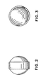
- Figure 2 is a plane view of a sintered pellet.
- Figure 3 is an end view of the pellet of Figure 2.
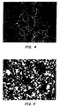
- Figure 4 is a photomicrograph of a sintered pellet.
- Figure 5 is a photomicrograph of a sintered pellet.
-
- Steel-tungsten alloys, containing from about 30% to about 65% by weight of tungsten can be formed into pellets suitable for use in shot shells by fabrication from the molten state. These pellets can have specific gravities in the range of from about 8 to 10.5. The pellets when formed from the molten state are prepared by a process consisting essentially of heating the binary alloy of steel-tungsten to a temperature about 1548°C, then increasing to not less than about 1645°C at which temperature the alloy evolves into a liquids phase when the tungsten is present in an amount of up to about 46.1%. The heated liquid alloy is then passed through refractory sieves having holes of a sufficient diameter, spaced appropriate distances apart to obtain the desired shot size, or quenched under specific conditions described hereinafter. Unwanted high viscosity is avoided by controlling molten alloy temperature and the resulting sieved alloy falls about 12 inches (1 inch = 2,54 cm) to about 30 inches, through air, argon, nitrogen or other suitable gas into a liquid such as water at ambient temperature, causing the cooled shot to form into spheres of desired sizes. Though generally of the desired shape, they can be further smoothed and made more uniform by mechanical methods such as grinding, rolling, or coining.
- Shot or pellet types of the present invention having different sizes are obtained by first melting the Fe/W alloys.
- A 200-g vacuum-arc melted button was prepared from 0.18% Carbon steel turnings an W powder (C10 grade). The dissolution of the W was both rapid and complete as indicated by a metallographic section. The alloy was predetermined to be 60wt%Fe/40wt%W having a calculated density of 10.3 g/cm. This compared favorably to its actual density measured at 10.46 g/cm3. Conventional lead shot is 97Pb/3Sb or 95Pb/5Sb which has a density of 11.1 gm/cm3 or 10.9 gm/cm3, respectively.
- A larger quantity of the above alloy was melted and poured through porcelain sieves of various hole sizes and spacings, then allowed to fall through a distance of air and ambient temperature water to produce about 3.1 pounds of shot.
- Molten alloy at 3000-3100°F was poured into a "water glass"-bonded olivine funnel containing a porcelain ceramic sieve and suspended 12" above a 6" I.D. Pyrex column containing 60" of 70°F water. The column terminated at a Pyrex nozzle equipped with a valve through which product could be flushed into a bucket. The porcelain ceramic sieve (part number FC-166 by Hamilton Porcelains, Ltd. of Brantford, Ontario, Canada) had been modified by plugging 58% of the holes with castable refractory to obtain a pattern of holes 0.080" dia. separated by spacings of approximately 0.200". Although an oxyacetylene torch was used to preheat the funnel/sieve assembly, a melt temperature of 1685°C resulted in very little flow through the sieve because of rapid radiative heat loss in the need for transporting molten metal from furnace-to-ladle-to-funnel in the experimental set-up employed. Increasing the melt temperature to 1745°C resulted in rapid flow through the sieve for approximately 15 seconds, resulting in the product described in Table 1 in terms of the particle size in contrast to the shape.
Size, in. Size Distribution
Wt., lb.Wt % - 1/2
+ 1/41.90 62.1 - 1/4
+0.1570.85 27.8 - 0.157
+ 0.0550.30 9.8 -0.055 0.01 0.3 3.06 100.0 - A sample of the -0.157"/+0.055" fraction was mounted polished, and etched to reveal microstructural details and microporosity.
- It was found that Fe/W alloy is particularly effective in forming relatively round, homogeneous diameter particles of
≤ 0.25" which become spherical in a free fall through about 12" of air, then through about 60" of water at ambient temperature (70°F). - It is believed that the pellet diameter is not strictly a function of the sieve hole diameter because droplets of spherical shape grow in diameter until a "drip-off" size is achieved. In addition, if the viscosity of the melted alloy is too low, multiple streams of metal will flow together forming a liquid ligament.
- This desired viscosity can be controlled by adjusting the temperature of the molten alloy to achieve the desired shot formation. That is, avoiding merging streams and tear drop shapes. This can be accomplished without undue experimentation with the specific equipment or apparatus sued by maintaining its temperature high enough so that at the point where the liquid metal enters the sieve its surface tension will cause the formation of spherical droplets from the sieve.
- By controlling the alloy melt and the sieving temperature, so-called ligaments or elongated shot are avoided as well as other anomalous sizes and shapes caused by unwanted high viscosity.
- The present invention overcomes many of the disadvantages of steel shot previously described, including less than desirable pattern density. Even though various pellet sizes can be used for steel shot shells, because the specific gravity of Fe is 7.86, its ballistic performance results for any given size is characterized by decreased force or energy, compared to lead and lead alloys.
- In overcoming this, the present invention includes cartridges of multiple shot sizes such as the so-called duplex or triplex combinations of different pellet sizes presently commercially available, which are said to increase the pattern density of the pellets delivered to a test target. By preselecting a particular distribution of shot sizes, i.e., diameters, and the proportion of the different sizes of pellets within the cartridge, an appropriate or desired pattern density can be achieved with a high degree of accuracy and effectiveness.
- In addition, the pellet charge of the present invention consist of various sized shot and include mixtures of both high and low specific gravity alloy pellets of different diameters.
- Heretofore, lead shot provided the standard against which accuracy was measured generally using only one size pellet. Lead-free shot pellets made of the Fe/W alloys of the present invention possess advantages both over toxic lead pellets and other metals substituted as replacements. This is particularly so because the different specific gravities in the mixture of shot pellets sizes, easily produced by the processes disclosed herein, provide a superior pattern density and relatively uniform delivered energy per pellet.
- By providing a predetermined pellet mix of two (duplex) or three (triplex) or more pellet combinations of varying diameters and varying densities or specific gravities, both the pattern density over the distance between discharge and on the target and the depth of impact of the smaller shot is improved. The energy of the shot combination is improved because there is little shot deviation on firing. The increased drag forces (per unit volume) encountered by a relatively smaller particle at a given velocity in air may be offset by constructing such a particle from alloy of a relatively higher specific gravity. The larger diameter steel shot on the other hand with a larger diameter and less specific gravity if correlated as described hereinafter to the smaller size Fe/W shot.
- Appropriate selection of shot sizes and the specific gravity of the alloys used for the various shot sizes can provide for the same energy delivered by each size to a preselected target. This can most graphically be demonstrated by the gelatin block test, etc. This will provide a significant improvement over the present use of steel pellets of the same specific gravity and different diameters used in the so-called "duplex" and "triplex" products. Because their diameters differ, shot pellets of the same specific gravity will exhibit different ballistic patterns.
- By determining the drag force of spheres, such as round shot pellets, traveling through a fluid, such as air, the drag forces of different metals having different radii and specific gravities can be determined.
- The drag forces per unit volume for both steel shot and FeW shot are determined and equated according to the following
Mixture Steel Shot Sizes Iron-40% Tungsten Shot Sizes #1 #6 (0.11" dia.) #7½ (0.095" dia.) #2 #4 (0.13" dia.) #6 (.11" dia.) #3 #2 (0.15" dia.) #4 (.13" dia.) #4 BB (0.18" dia.) #2 (.15" dia.) - Further, improvements in the ballistic performance rust prevention and abrasiveness to steel barrels can be achieved by coating the pellets of the present invention with a suitable layer of lubricant or polymeric or resinous material or surface layer of a softer metal. The mixed shotshell pellets where steel alone is the material of choice for one or more of the pellet sizes may also advantageously be coated as described herein to improve resistance to oxidation. The covering or coating can be of any suitable synthetic plastic or resinous material softer metal layer, that will form an oxidation resistant or lubricant film which adheres to the pellets. Preferably, the coating should provide a non-sticking surface to other similarly coated pellets, and be capable of providing resistance to abrasion of the pellet against the steel barrel. Typically suitable materials can be selected from petroleum based lubricants, synthetic lubricants, nylon, Teflon, polyvinyl compounds, polyethylene polypropylene, and derivatives and blends thereof as well as any of a wide variety of elastomeric polymers including ABS polymers, natural and synthetic resins and the like. Coatings may be applied by methods suitable to the materials selected which could include hot melt application, emulsion polymerization, solvent evaporation or any other suitable technique that provides a substantially uniform coating that adheres well and exhibits the previously described characteristics. The application of a metal layer will be more fully described hereinafter particularly with respect to pellets formed by powder metallurgical processes.
- In addition, the shot shells of the present invention can employ buffering materials to fit either interstitially with the shot charge or not, depending on the performance parameters sought. Granules of polyolefins or polystyrene or polyurethane or other expanded or solid materials can be utilized and some have been employed in conventional lead and lead alloy and steel shot charges in shot shells. Such buffering with or without shot coatings may advantageously be employed to add dampening and shot and barrel lubrication properties. The shot shells of the present invention can be fabricated with or without conventional shotcup wads.
- Further, it has been learned that shot can be cast from the alloys described herein under specific conditions, further described hereinafter, that perform suitably as lead shot and steel shot substitutes in shot shells.
- Experiments have demonstrated that adding carbon (2.5%) to 60 Fe 40W alloy caused the molten droplets to shatter into smaller spheres upon impact with water, producing a desirable distribution of shot sizes with average bulk densities of 10.1 g/cm3. Later experiments evaluated different methods of dispersing molten alloy droplets into water for two different alloys: 57.5
Fe 40@ 2.5C and 51.5Fe 46W 2.5C. Input material was pure W powder and Sorel iron (4.3%C). The densities of the resulting products were 10.0 and 10.2 g/cm3, respectively. Other experiments demonstrated that ferro-tungsten could be readily substituted for pure W and that varying funnel orifice diameter and quench medium (water vs. brine) would be employed to control product size distributions. The presence of internal cracks in the brine-quenched product indicates that this quench medium yields an excessively high cooling rate. Additional refinements in process technology can be done using drop towers as disclosed by Bliemeister in U.S. Patent Nos. 2,978,742 and 3,677,699. - Using 40% of pure W and 60% Sorel iron (4.3%C), molten alloy was passed through a porcelain sieve with 0.060" dia. holes and allowed to fall in air for about six (6) feet into a bucket of water (≈14" deep). The molten streams shattered upon impact with the water, producing size distributions of shot typical of that shown in Table 13.
SIZE, mesh WT., g WT.% +5 221.7 26.3 -5
+10455.0 54.0 -10
+1474.6 8.9 -14
+2074.3 8.8 -20 16.4 2.0 TOTAL 842.0 100.0 - It was observed that much of the shot was agglomerated due to incomplete solidification as the shot piled up on itself in the bottom of the bucket. A sample of unagglomerated shot had an average bulk density of 10.12 g/cm3. Actual carbon assay of the product was 2.52=2.55%, very close the calculated assay of 2.58%. It was very difficult to accurately measure pouring temperature, but the estimate was ≈1350°C.
- A fixture was devised consisting of a graphite funnel suspended above a steel sleeve which in turn was positioned above a water-quenching tank with a sloped bottom. The steel sleeve was equipped with a "spider" so that molten metal could be "splattered" onto a ceramic pedestal to shatter the stream into droplets contained by the steel sleeve. Using this apparatus with and without the ceramic pedestal, six (6) experiments were conducted to evaluate two different funnel apertures (0.090" and 0.125"). In addition, two experiments (Runs #6 and #8) were run in which molten alloy was poured into a high-velocity water stream ("granulator"). As shown in Table 14, Run #7 is equivalent to Run #1 except for higher W concentration in the former. This was done in an attempt to obtain higher density. In all cases, Sorel iron was alloyed with pure W powder as feed.
Run Fe (ibs) W (ibs) Brick Aperture (in) Free Fall
(in)Furnace (Temp C) Comments 1 9.90 6.60 No (1) 0.125 93 1513 40W 2 9.65 4.65 No (1) 0.090 93 1532 40W 3 8.60 5.76 Yes (1) 0.125 79 1578 40W 4 7.30 4.90 Yes (1) 0.125 52 1473 40W 5 8.50 5.70 No (5 ea) 0.125 93 x 40W 6 8.30 5.60 x x x x granulator. 40W. hr flow 7 8.90 7.55 No (3 ea) 0.125 93 1490 46W 8 9.25 6.20 x x x x granulator. 40W. lo flow - Observations made during casting include:
- (1) "Spattering" from a ceramic pedestal produced undesirably fine particle sizes.
- (2) Granulation by water jet produced non-spherical parties.
- (3) Actual casting temperatures were approximately 1325-1350°C with furnace-funnel transfer times of 30-60 sec.
-
- Table 15 presents size distributions for all eight experiments obtained by screening through 5-, 6-, 7-, 8-and 10-mesh screens. Most products from Runs 1, 3, 4, 5 and 7 were generally spherical, although +5-mesh fractions again consisted of agglomerated particles, indicating that water depth (≈16") was inadequate. Particles from Run #2 were somewhat "pancake" shaped, whereas "granulated" particles from Runs 6 and 8 were quite "irregular" in shape.
Test 1 2 3 4 5 6
(gran)7 8
(gran)+5M 42.48 35.90 41.43 35.34 64.81 10.42 54.71 20.93 - 5
+612.30 14.22 6.93 5.27 7.88 4.70 11.49 3.77 -6
+ 714.52 16.03 7.97 5.83 7.80 5.89 10.44 6.75 - 7
+ 88.45 10.30 5.27 6.37 5.13 6.52 6.86 9.99 -8
+106.58 7.42 4.86 6.29 3.83 6.54 5.38 10.63 -10 15.66 16.13 33.55 40.9 10.55 65.93 11.12 47.94 Total
Wt.,g1607.3 4275.6 1901.6 559.9 7178.8 6138.0 2261.9 279.55 -5
+1041.85 47.97 25.03 23.76 24.64 23.65 36.17 31.14 - Average bulk densities for the 40% W and 46% alloys were 10.0 g/cm3 and 10.22 g/cm3, respectively. An actual analysis of the 46% alloy (Run 7) showed it to be 43.5% W, indicating incomplete dissolution of the W powder:
W 43.5% As 2.8 ppm C 2.5% Sb < 1 ppm Si 3330 ppm Bi < 1 ppm Mn 890 ppm Pb 13 ppm P 450 ppm Sn 6.1 ppm S 68 ppm Mo < 100 ppm Cu 160 ppm Ni 800 ppm Cr 210 ppm - Photomicrographs of typical pellets from two different size fractions of the 46% W alloy (Run 7) were made. Carbides were visible as are micropores formed by shrinkage during solidification.
- Seven different experiments were conducted for each of two alloys made by blending -1/4" crushed ferro-tungsten (analysis per Table 7 below) and Sorel iron:
- Alloy A - 58Fe 40W 2C
- Alloy B - 53.2Fe 45W 1.8C Calculations based on the 77.75%W content of ferro-tungsten established ferro/Sorel charge ratios of 1.0833 for Alloy A and 1.4038 for Alloy B.
-
- Table 19 is a summary of test conditions used for the 14 casting runs. Temperatures were measured in the SiC crucible just prior to its removal from the induction furnace. Transfer times from the furnace to the elevated pouring platform were held nearly constant at approximately 30 seconds. The drilled graphite funnels were preheated and maintained at approximately 1675°F prior to pouring by means of a large gas torch. Based upon spot measurements, melt temperature was observed to drop by approximately 125°F during transfer to the pouring platform and by an additional 290°F after filling the funnel. The "casting temperature" estimates presented in Table 10 were arrived at by subtracting 415°F from the furnace temperatures.
Test Conditions Run Alloy Funnel Holes Quench
MediumFurnace Temp,
°FCasting
Temp, °F1 A Single, 0.125" water 2850 2435 2 B " water 2868 2453 3 A " 10% NaCl 2930 2515 4 B " 10% NaCl 2879 2464 5 A " 10% NaCl + high agit. 2922 2507 6 B " 10% NaCl + low agit. 2886 2471 7 A 3 ea, 0.093" 10% NaCl 2873 2458 8 B " 10% NaCl 2910 2495 9 A+2% SiC " 10% NaCl 2935 2520 10 B+2% SiC " 10% NaCl -- -- 11 A 3 ea, 0.078" 10% NaCl -- -- 12 B " 10% NaCl -- -- 13 A 3 ea, 0.086" 10% NaCl 2917 2502 14 B " 10% NaCl 2947 2532 - Graphite funnels were suspended above a stainless steel dumpster with a sloped bottom. In the present study, the dumpster was completely filled with water and was positioned to allow shot to free-fall 86" in air into 26" of water depth (as opposed to the 14" depth of the previous studies, which was found to be inadequate).
- Product from the 14 runs was screened on 5-, 6-, 7-, 8- and 10-mesh screens to determine size distributions. Samples of the 56 fractions in the -5M/+10M range were mounted and polished for metallographic examination.
- Table 20 presents particle size distributions of the 14 runs. An important factor to consider is that coarse (+5 mesh) particles were observed to form only from cold, viscous droplets obtained as the last metal exited the graphite funnel. These droplets do not shatter upon impact with the quenchant. The important point to note is that this scenario would not occur in a continuous operation where temperatures would be controlled under "steady state" conditions.

- Average bulk densities for the -6M/+7M fractions were determined by water displacement as presented in Table 21. Values in parentheses were additionally obtained by diameter measurements of ten pellets per sample.
Pellet Densities (-6M/+7M) Run 1 2 3 4 5 6 7 8 9 10 11 12 13 14 Wt,
g 10 08 10 58 8.39 14 74 9.68 10 87 10 35 10 25 9 91 11 56 10 02 9 90 9 23 10 70 Vol.
cm31 1 1 1 0 9 1.4 1.0 1 1 1 0 1 0 1 0 1 1 1 0 1 1 0 9 1 0 ρ
g/cm3(10 3)
9.2(10 6)
9.6(10 5)
9.310.5 9 7 9 9 10 4 10 1 9 9 10 5 10 0 9 0 10 3 10 7 - Bulk samples and metallographic mounts of all 56 size fractions between 5- and 10-mesh were examined by the inventor whose qualitative comments appear in Table 22.
Particle Shape and Integrity (-5M/+10M) Run Shape Description Internal Integrity 1 generally spherical some porosity, no cracks 2 generally spherical some porosity, no cracks 3 generally spherical some porosity, many cracks 4 generally spherical some porosity, many cracks 5 many flattened pieces some porosity, many cracks 6 many flattened pieces some porosity, many cracks 7 generally spherical some porosity, many cracks 8 generally spherical some porosity, many cracks 9 many broken pieces, some flattened some porosity, many cracks 10 many broken pieces, some flattened some porosity, many cracks 11 generally spherical some porosity, many cracks 12 generally spherical some porosity, many cracks 13 generally spherical some porosity, many cracks 14 generally spherical some porosity, many cracks - In comparison with the earlier experiments, far fewer agglomerated ("twins", "moon-planet", etc.) particles were observed. This was probably due to the fact that increased water depth was used in the present studies. Another qualitative observation is that larger spheres tend to be higher in porosity, some even appearing as hollow shells. We again attribute this to cold, viscous droplets near the end of a run which would not be encountered in a controlled, continuous operation.
- A summary of the inventors' observations and opinions include:
- 1. Brine quenching in 10% NaCl, while having a beneficial effect on particle size, results in cooling rates so fast as to cause cracking within the parties.
- 2. Molten stream size, as determined by funnel orifice diameter, has a significant influence on particle size distribution. Smaller orifices tend to produce a higher percentage of desirable (for shotgun applications) sizes.
- 3. Quenchant agitation causes non-spherical particles to form during solidification.
- 4. Eliminating coarse (+5 mesh) particles by controlling temperature (and related viscosity) in a continuous process should place 75-85% of the product within the desired size range.
- 5. Particle shape and density must be addressed before declaring any particles to be final product.
- 6. Addition of 2% Sic to either alloy (A or B) produced visually fluid melts, but these alloys were quite brittle.
- 7. The 40% W and 45% W alloys did not appear to behave in significantly different ways. It is contemplated that it is possible to further increase W concentration (in order to increase density) and still retain castability at tolerable temperatures.
- 8. Ferro-tungsten is readily alloyed with Sorel iron.
-
- These experiments appear to indicate that a scaled-up production process will be feasible. One skilled in this art would envision a continuous melting process in which two relatively small (e.g., 500 lb) induction furnaces supply a constant flow of molten alloy to a tundish equipped with ceramic orifices. Product would be easily removed from the quench tank by magnetic methods, followed by screening and shape/density separation methods commonly used by mineral and metallic shot industries. Acceptable product would be bled off, heat-treated and optionally final-ground. All non-product would be recycled back to the melting process.
- A high recycle load to the melting process (e.g., 75%) should be tolerable.
- In subsequent experiments, the inventor has explored the use of a slow quenching medium (0.05-0.10% polyvinyl alcohol in water), smaller funnel orifice diameter (0.078", 0.062" and 0.050"), and "high" (84") versus "low" (24") free-fall distances, with favorable results to those described herein.
- The following Table 23 illustrates the effects of these variables on FeW particle-size distribution. Product evaluations are presently incomplete, but here are some preliminary observations.
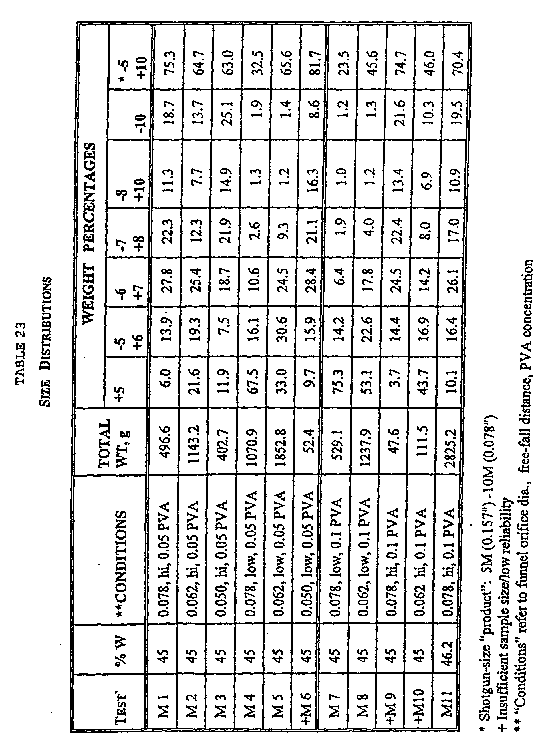
- When compared against results of the previous experiments, slow quenching with PVA produced shot with markedly improved sphericity.
- PVA quenching also resulted in finer particle size distributions than were obtained with, for example, fast brine quenching, all other known variables (e.g., melt temperature, orifice size, free-fall distance) being held constant. Product (-5M/+10M) yields with PVA quenching exceeded 70%, compared with ≤57% for brine quenching.
- Free-fall distance (from bottom of sieve to quench liquid surface) has a significant effect on particle size distribution, a large drop resulting in increased shattering of the molten droplets upon impact and, therefore, a finer particle size distribution.
- The following generalizations based on the data are believed to be valid.
- Particle size distribution may be effectively controlled by varying funnel orifice size and, independently, by varying free-fall distance. In all experiments to date, a relatively wide spectra of sizes were obtained.
- Particle shape (i.e., "sphericity") is strongly influenced by quench medium. This is primarily a function of the different cooling rates obtained during solidification determined by the various thicknesses of vapor blankets surrounding the particles.
- The latest experiments were successfully performed using an alloy containing 46.2% W. This alloy was at 2953°F, as opposed to 2900°F used for melting 45% W alloy. Calculated carbon content for this alloy is 1.72%. Melt fluidity was not noticeably lower in this alloy. The available ternary phase diagrams indicate that increasing carbon up to around 3.0-3.5% may allow casting of alloys containing perhaps as much as 60-65% W at temperatures of 1500-1550°C.
- The selection of different quench media and sieve size and height can be varied as well as composition ranges to enhance desired particle size distributions from various temperatures of the molten material.
- A series of 8 runs were conducted to pass a molten alloy of ferrotungsten plus Sorel iron having a composition on a weight basis of 52.3% Fe, 46% W, and 1.7% C through a SiC crucible having drilled orifices of 0.078" dia. with 3 holes per funnel. Three different heights of 84 inch, 54 inch and 24 inch were used and the molten metal fell into water containing 0.04% PVA. During the melting, gaseous argon was directed onto the top of the SiC crucible. As indicated in Table 24, certain metals were killed or deoxidized with Al or Hf immediately prior to removal from the furnace.
Test Conditions Test
RunFree-fall
Height, in.Deox.
PracticeFurnace
Temp °C1 84 None 1603 2 84 Al (0.1%) 1615 3 84 Hf (0.5%) 1639 4 54 None 1613 5 54 Al (0.1%) 1617 5R 54 Al (0.1%) 1631 6 54 Hf (0.5%) 1648 7 24 Al (0.1%) 1631 - Run 5R was a repeat of Run 5 to verify reproducibility.
- The size distribution of the products are presented in Table 25. The focus in these experiments was on achieving smaller size shot and thus particles larger than 5 mesh (+5m) were not considered to be the desired product.
Size Distributions Test
RunWeight % of Total +5m -5+6 -6+7 -7+8 -8+10 -10 -5+10 1 10.25 12.09 21.08 16.61 12.72 27.26 62.49 2 38.72 23.73 18.09 6.90 4.46 8.09 53.19 3 24.37 18.36 22.54 12.82 7.48 14.44 61.19 4 37.79 23.18 20.43 7.99 4.60 6.01 56.20 5 29.17 22.10 23.22 10.48 5.79 9.24 61.59 5R 24.57 24.33 25.79 10.24 5.65 9.43 66.0 6 33.81 25.60 21.62 8.02 4.59 6.35 59.84 7 57.50 21.56 15.44 2.96 1.28 1.26 41.24 - Due to the extensive degree of gas porosity in non-deoxidized and Hf-killed products, density values were not determined. The Al-killed products had densities between 9.6 g/cm3 and 10.0 g/cm3.
- The +5m fraction of Run 5 was studied by XRD and found to contain two phase of ferritic iron and Fe3W3C. Although at least one available Fe-W-C phase diagram indicates that a third phase of WC may be present in small concentrations at a 1000°C equilibrium, none was detected.
- Table 26 presents a chemical analysis for the +5 mesh products from Runs 4, 5 and 6 where there was no deox, Al-killed and Hf-killed as well as a sample of the slag skimmed from the Run 5 melt.
Chemical Composition Sample (ppm unless noted as %) W C O N H Al Hf Si Fe +5m#4 46.7
%2.21
%470 56 3 <40 64 0.75
%-- +5m#5 45.1
%2.58
%180 73 5 620 27 0.71
%-- +5m#6 45.6 2.33 250 62 <3 40 <25 0.73
%-- Slag#5 50.2
%1.24
%1.5
%240 58 0.14
%<0.05
%1.18
%36.7
% - These runs demonstrate the effectiveness of Al as a deoxidizer and its beneficial effect on gas porosity. Control over average product particle size by varying free-fall height was confirmed with the exception of the data point for Run 2 which was coarser than expected. It is speculated that this may be due to a delay in pouring which resulted in a somewhat cooler metal and thus possibly a more viscous metal during casting.
- This example presents the result of two studies. The first was to scale up the amount of material produced according to Runs 5 and 5R of Example 17. The other study was to consider the effectiveness of the patented Air Liquide Corp. process of SPAL™ in preventing the dissolution of oxygen during melting.
- The SPAL™ process consists of tricking liquid argon onto the top of the charge throughout the entire melting cycle. In most traditional ferrous alloys, there is very little oxygen pick up occurring during pouring through air subsequent to melting and thus the use of the SPAL™ process would be sufficient.
- The experimental system consisted of pouring from the melt furnace into a rammed refractory-lined ladle. The ladle was elevated by means of a bridge crane and pouring was done into a sieve-bottomed graphite basin suspended at 74 inches above a water quench tank where the water contained 0.05% PVA. The product was collected in a shallow stainless steel box about 4 ft square at the bottom of the tank. The tank was a steel dumpster of about 44 inches deep, 51 inches wide by 72 inches long. The catch box was equipped with screened "windows" at each corner to allow drainage upon removal from the quench tank and during subsequent rinsing with water. Failure to remove all traces of PVA solution results in agglomerated product after drying, which is very difficult to break apart. Drying of the product was conducted in a circulating hot air oven at 200°F.
- The graphite pouring basin/sieve assembly has a row of about 9-10 porcelain sieves. The stock sieve size of 0.080 inch dia. holes was plugged with mortar and then perforated to obtain the desired hole patterns. The pattern evolved from experience from the first four melts which had more closely spaced patterns and the final form was used with the last 9 melts.
- The entire pouring basin/sieve assembly was wrapped with Kaowool except for the bottom surface which was preheated to 1,000-1,100°C with a propane torch prior to each casting run. The ladle was also propane heated to a somewhat lower temperature.
- The Sorel iron and ferrotungsten raw material was used to formulate a 46.3% W alloy. Relatively small amounts were used. Aluminum (0.15%) was added to the ladle in the first two melts, but to the furnace in melts 3 and 4. Melts 5-13 were not Al-killed, but were protected by the SPAL™ process.
- The melt data for the 13 runs is given in Table 27.
Melt Data Run Input Wt.
lbProduct
Wt. lbFurnace
Temp °CQuench
Temp °CDeox 1 150 83 1650 18 Al to ladle 2 306 201 1606 19.5 Al to ladle 3 304 66 1616 27 Al to ladle 4 301 49 1677 24 Al to ladle 5 300 173 1617 31 SPAL 6 303 142 1621 32 SPAL 7 302 68 1609 37 SPAL 8 301 291 1770 30 SPAL 9 300 97 1662 43 SPAL 10 307 242 1750 41 SPAL 11 155(recycle)
83 (virgin)71 1770 34 SPAL 12 150(recycle)
83 (virgin)207 1740 37 SPAL 13 304(recycle) 94 -- 48 SPAL Total 3040(virgin) 1784 Size Distribution Size Run # Weight Percent Total
Wt. g+3m -3m
+4m-4m
+5m-5m
+6m-6m
+7m-7m
+8m-8m
+10m-10m 1/16 #1 14.06 17.63 12.06 12.10 13.54 9.34 7.39 14.08 2136.2 1/32 #2 17.56 18.29 8.90 10.69 13.54 10.61 8.29 17.13 2596.4 1/8 #3 17.59 14.63 9.80 11.02 12.97 10.03 7.38 16.59 3316.7 1/16 #4 15.50 13.01 9.35 11.15 13.34 10.89 8.59 18.17 1366.2 1/32 #5 9.02 11.60 11.27 13.55 15.79 12.11 8.51 18.14 2725.2 1/32 #6 36.34 14.56 9.90 8.77 8.58 6.23 4.54 11.09 2071.9 1/16 #7 5.86 17.80 14.72 12.33 13.79 10.88 7.90 16.72 1588.5 1/32 #8 19.40 16.29 11.74 13.04 11.91 8.52 5.69 13.41 4133.5 1/16 #9 0.89 8.69 10.96 14.22 17.26 13.65 10.63 23.72 2650.4 1/32#10 4.22 11.64 10.39 14.06 17.51 12.66 9.43 20.09 2897.4 1/16#11 7.05 12.94 11.24 14.01 15.45 11.32 8.98 19.0 1972.2 1/32#12 17.84 17.38 9.87 12.17 12.27 9.00 6.56 14.91 2462.1 1/16#13 6.41 11.57 11.89 13.31 15.36 11.74 9.01 20.71 2534.2 Average 13.21 13.92 10.93 12.34 13.95 10.54 7.90 17.22 -- Chemical Composition and Density Run Al % C % Fe % N ppm O ppm Si % W % Density g/cm3 1 0.15 1.56 57.9 45 460 0.23 41.8 9.56 2 0.16 1.67 56.0 48 860 0.11 43.8 9.67 3 0.16 1.63 54.7 38 690 0.11 45.0 9.60 4 0.15 1.59 53.0 40 720 0.12 46.7 10.1 5 <0.01 1.52 59.2 55 760 0.12 40.7 8.58 6 <0.01 1.82 54.3 57 1350 0.071 45.6 8.64 7 <0.01 1.85 55.5 49 530 0.081 44.4 8.73 8 <0.01 1.59 52.0 41 870 0.093 47.9 (9.54)
7.859 <0.01 1.65 53.8 36 550 0.12 46.1 8.69 10 <0.01 1.58 50.6 45 1210 0.10 49.3 8.4 11 <0.01 1.78 59.6 43 420 0.10 40.3 (9.98)
8.012 <0.01 1.65 52.6 42 480 0.074 47.3 8.3 13 <0.01 1.72 59.6 48 580 0.053 40.4 8.2 - The data from Table 29 indicates that while the SPAL™ process adequately protects the alloy during melting, gas porosity results from pouring FeW alloy through the air. Densities on non Al-killed runs 5-13 are unacceptably low. The Fe + W total for all 13 groups are 99-100% indicating that the variations in W content are real and probably result from alloy inhomogeneity.
- This example sets forth experiments run to produce coarser shotgun sizes such as #2 shot having a 0.15 inch diameter. Sintered pellets formed from 70 wt.% - 100 mesh ferro-tungsten (-150 microns) and 30 wt.% iron powder, sintered at near 1540°C for 4 hours, were remelted and the W content was increased to 50% and 55% by adding pure W powder to the 46.3% alloy. Both the SPAL™ process and Al-killing (0.15%) were used to minimize gas porosity. The free-fall height was reduced to 24 inches to obtain coarser distributions.
- Using the equipment described in Example 18, there were 12 runs made as set forth in Table 30.
Melt Data Run W % Furnace
Temp °CPVA % Comments 1 50 1709 0.05 2 55 1704 0.025 3 55 1673 0.025 4 55 1683 0.025 5 55 1670 0.025 6 55 1720 0.025 pump agitated 7 55 1730 0.025 impeller agitated 8 55 1730 0.025 9 55 1717 Deep tank 10 55 1760 Deep tank, 0.095 inch sieves on each end of row 11 55 1705 Deep tank 12 55 1730 Deep tank, 0.095 inch sieves on each end of row - During the runs it was observed that the higher W content and the higher melting point appeared to make the alloy more difficult to pass through the sieve and also more of the +3 mesh agglomerate were formed. The process was changed during the course of the runs as noted in Table 30 above. After run 1, the PVA concentration was reduced from 0.05% to 0.025% in an attempt to reduce the volume of vapor created during quenching. On run 6, the top region of the quench medium was agitated by means of a pump in an attempt to break up the vapor pocket. In run 7, more vigorous agitation was effected in the top region of the bath by means of an impeller.
- In runs 9-12, an 8 yd3 dumpster was substituted for the previous 4 yd3 dumpster. This doubled the volume of the quench medium and increased the liquid depth from 42 inches to 82 inches. In an attempt to allow molten alloy to flow more freely at the ends of the row of sieves, 0.095 inch diameter sieve sections were substituted for the 0.080 inch diameter end sections on runs 10 and 12. The size distribution and density of the products is set forth in Table 31.
Size Distribution and Density Run Weight Percent Density
g/cm3-3m
+4m-4m
+5m-5m
+6m-6m
+7m-7m
+8m-8m
+10m-10m Sample
Wt. g1 23.4 19.9 19.3 17.3 10.1 5.2 4.8 2820.5 (50%W)
10.332 26.7 22.0 18.8 15.8 7.8 4.0 4.9 1985.6 10.82 3 29.0 20.0 19.9 14.0 7.4 4.2 5.5 2251.9 11.08 4 22.6 22.3 20.6 17.1 8.9 3.8 4.7 2017.2 11.34 5 28.1 19.7 17.6 15.3 8.9 4.8 5.6 1262.8 11.20 6 25.1 20.8 18.8 16.5 9.4 4.3 5.1 1937.2 11.36 7 32.8 20.7 16.2 13.6 7.2 4.1 5.4 2998.1 11.20 8 22.9 19.8 18.8 16.0 10.5 5.3 6.7 2702.2 11.03 9 29.4 19.6 19.5 14.9 8.1 3.8 4.7 2541.2 11.06 10 30.7 20.0 17.5 14.3 7.9 4.3 5.3 2673.9 11.04 11 31.1 21.0 17.7 14.2 7.1 4.0 4.9 1570.1 11.14 12 25.2 20.3 16.5 17.3 8.9 5.5 6.3 2404.4 10.80 Avg. 27.25 20.5 18.35 15.5 8.5 4.4 5.3 -- (55%w) 11.09 - The density was determined by water displacement method on a sample of about 200 g of mixed sizes.
Mass Balances Run Wt.
Melted, lb.Wt.thru
Sieve, lb.Wt
+3m, lb.Wt Product
-3m, lb.1 241.4 192.8 91.2 101.6 2 349.4 234.7 95.5 139.2 3 334.1 131.5 46.5 85.0 4 308.8 35.9 ∼1.0 34.9 5 289 63.8 ∼7.0 56.8 6 331.5 109.9 35.5 74.4 7 357.5 194.7 78 116.7 8 288.1 42.2 ∼1.0 41.2 9 286.4 80.1 36 44.1 10 292.5 177.6 74.5 103.1 11 362 64.8 33 31.8 12 353 118.1 38 80.2 Total 3,793.7 1,446.2 537.2 909.0 - The data in Table 32 illustrates that it was often difficult to obtain large flows of molten 55% W alloy through the sieves before plugging occurred and that large percentages of +3 mesh agglomerates were obtained in some runs.
- Shadow images of the particle shape for the particles have also been examined. When an attempt was made to separate particles from each other, the particles that appeared to be touching were, in fact, agglomerated "twins," triplets," etc. This shape distribution is not desirable for obtaining the desired uniform particle sizes for producing ground spherical shot.
- This example illustrates a casting method to produce uniform size particles which can be ground to produce shot.
- Porcelain sieves with 0.080 inch diameter holes were sealed on one major surface with mortar. A powder mixture of 30% Fe, 68.5% Starck ferro-tungsten (82.9% W, -325 mesh) and 1.5% paraffin was poured into the top, unsealed, surface of the sieve. The filled sieve was manually vibrated and leveled by scraping excess powder off with a putty knife. The packed sieves were partially covered with a graphite plate to minimize oxidation of the powder and placed in a resistance furnace with 1700°C max. Kanthal elements.
- The filled sieves were given the following thermal cycle to melt the powder mixture. First, a ramp to 1600°C at 50°C/min. Then they were held for 30 minutes at 1600°C followed by a furnace cool to about 1200°C. Finally, they were air cooled to room temperature.
- The fully loaded sieves each contained about 56 g of powder at a tap density of about 4.0 g/cm3. After melting and solidification, the as-cast density was measured on a 71 g sample as 10.92 g/cm3 by the water-displacement method. The cast right cylinders produced in the central, graphite-protected regions of the sieves were relatively uniform in shape with the variation in length being the result of variable mortar thickness in the sieve bottom.
- It is contemplated that this batch process could be scaled up and automated. The process is suitable to using the large quantities of grinding dust that is generated with spherical grinding operation required for either granulated/cast or powder metallurgy products. These fines could be used as the input material according to this process.
- When grinding particles to make spherical shot, any uniform size particle can be ground including the right cylinders made in these sieves. However, even more optimum results can be achieved by applying a given weight of material to depressions machined into the surface of a flat mold. Upon melting, each liquid drop will form a pseudosphere, due to the surface tension and the shape of the bottom of the depression. It is contemplated that the particles would presumably be uniform in size and shape and easily grindable.
- The process will be easy to automate. Either endless belts or rotating wheels would continually advance through a stage of die-filling, melting, cooling and discharge. The temperature control would not be of much concern as there is practically no upper limit. The process cycles for the machinery could be quite short because there is no reason to allow permanent molds to cool much below the alloy melting point before refilling.
| Ferro-Tungsten Analysis | |||
| W | 77.75% | Cu | 620 ppm |
| Si | 0.168% | As | 360 ppm |
| S | 500 ppm | Sn | 250 ppm |
| P | 260 ppm | Pb | 350 ppm |
| C | 440 ppm | Sb | 110 ppm |
| Mn | 0.154% | Bi | 200 ppm |
| Sorel Iron Analysis | |
| C | 4.3% |
| S | 250 ppm, max. |
| Si | 0.40%, max. |
| Mn | 350 ppm, max. |
| P | 300 ppm, max. |
| Charge Makeup | |||||
| Run | Weight, Sorcl, lb. | Weight, Ferro-W, lb. | Weight, Recycle, lb. | Weight, SiC, lb | Total Weight, lb |
| 1 | 6.80 | 7.37 | 0 | 0 | 14.17 |
| 2 | 7.78 | 10.92 | 0 | 0 | 18.70 |
| 3 | 6.80 | 7.36 | 0 | 0 | 14.16 |
| 4 | 6.20 | 8.70 | 0 | 0 | 14.90 |
| 5 | 3.52 | 3.81 | 3.97 (Run 1) | 0 | 11.30 |
| 6 | 6.86 | 9.62 | 0 | 0 | 16.48 |
| 7 | 5.44 | 5.89 | 0 | 0 | 11.33 |
| 8 | 3.30 | 4.63 | 3.29 (Run 6) | 0 | 11.22 |
| 9 | 4.86 | 5.26 | 0 | 0.20 | 10.32 |
| 10 | 4.44 | 6.23 | 0 | 0.21 | 10.88 |
| 11 | -- | -- | -- | -- | -- |
| 12 | -- | -- | -- | -- | -- |
| 13 | 4.58 | 4.96 | 0 | 0 | 9.54 |
| 14 | 0 | 0 | 11.11(var. runs) | 0 | 11.11 |
Claims (9)
- A process for making high specific gravity essentially spherical non-toxic, lead free solid pellet shot comprising the steps of:a) preparing an alloy consisting of from 30% to 65% by weight of Tungsten and 70% to 35% by weight of iron and from 2.5% to 3.5% by weight of carbon having a calculated specific gravity in the range of from 8 to 10.5 g/cm3;b) melting said alloy at 1645°C to 1760°;c) pouring said molten alloy at a temperature above 1550°C through at least one orifice of a sieve of preselected orifice opening size and allowing the sieved alloy to fall by gravity through a gas into a liquid forming spheres and permitting said spheres to cool; andd) recovering the cooled spheres of alloy shot.
- A process according to claim 1 characterised in that the alloy contains from 30% to 50% by weight of Tungsten and 50% to 70% by weight of iron.
- A process according to claim 1 or 2 characterised in that the alloy is melted under argon.
- A process according to any one of claims 1 to 3 characterised in that the pellet spheres are classified into preselected sizes.
- The process according to any one of claims 1 to 4 characterised in that the gas is air and the liquid is water, both at ambient temperature.
- A method according to claim 1 or 2 characterised in that the carbon content of the melt is from 3.0% to 3.5% by weight.
- A method according to any one of claims 1,2,6 characterised in that the quench medium is water or water with up to 10% by weight added soluble salt, or water containing 0.05% to 0.10% of a water soluble vinyl polymer.
- A method according to claim 7 characterised in that the quench medium is water containing 0.05% to 0.10% polyvinylalcohol.
- A method according to any one of claims 1,2,6 characterised in that the gaseous media selected is air.
Applications Claiming Priority (5)
| Application Number | Priority Date | Filing Date | Title |
|---|---|---|---|
| US323690 | 1994-10-18 | ||
| US08/323,690 US5527376A (en) | 1994-10-18 | 1994-10-18 | Composite shot |
| US08/474,890 US5713981A (en) | 1992-05-05 | 1995-06-07 | Composite shot |
| US474890 | 1995-06-07 | ||
| PCT/US1995/013294 WO1996011762A1 (en) | 1994-10-18 | 1995-10-18 | Composite shots and methods of making |
Publications (3)
| Publication Number | Publication Date |
|---|---|
| EP0788416A1 EP0788416A1 (en) | 1997-08-13 |
| EP0788416A4 EP0788416A4 (en) | 1999-12-01 |
| EP0788416B1 true EP0788416B1 (en) | 2003-07-16 |
Family
ID=26984108
Family Applications (1)
| Application Number | Title | Priority Date | Filing Date |
|---|---|---|---|
| EP95940516A Expired - Lifetime EP0788416B1 (en) | 1994-10-18 | 1995-10-18 | Method of making composite shots |
Country Status (7)
| Country | Link |
|---|---|
| US (1) | US5713981A (en) |
| EP (1) | EP0788416B1 (en) |
| AT (1) | ATE245075T1 (en) |
| AU (1) | AU4193896A (en) |
| CA (1) | CA2203174A1 (en) |
| DE (1) | DE69531306T2 (en) |
| WO (1) | WO1996011762A1 (en) |
Families Citing this family (33)
| Publication number | Priority date | Publication date | Assignee | Title |
|---|---|---|---|---|
| US5399187A (en) * | 1993-09-23 | 1995-03-21 | Olin Corporation | Lead-free bullett |
| US6112669A (en) * | 1998-06-05 | 2000-09-05 | Olin Corporation | Projectiles made from tungsten and iron |
| US7267794B2 (en) * | 1998-09-04 | 2007-09-11 | Amick Darryl D | Ductile medium-and high-density, non-toxic shot and other articles and method for producing the same |
| US6527880B2 (en) | 1998-09-04 | 2003-03-04 | Darryl D. Amick | Ductile medium-and high-density, non-toxic shot and other articles and method for producing the same |
| US6270549B1 (en) | 1998-09-04 | 2001-08-07 | Darryl Dean Amick | Ductile, high-density, non-toxic shot and other articles and method for producing same |
| JP2000192112A (en) * | 1998-12-25 | 2000-07-11 | Nippon Steel Corp | Method and apparatus for producing fine metal spheres |
| US6248150B1 (en) | 1999-07-20 | 2001-06-19 | Darryl Dean Amick | Method for manufacturing tungsten-based materials and articles by mechanical alloying |
| US6447715B1 (en) | 2000-01-14 | 2002-09-10 | Darryl D. Amick | Methods for producing medium-density articles from high-density tungsten alloys |
| US7217389B2 (en) * | 2001-01-09 | 2007-05-15 | Amick Darryl D | Tungsten-containing articles and methods for forming the same |
| US6551375B2 (en) | 2001-03-06 | 2003-04-22 | Kennametal Inc. | Ammunition using non-toxic metals and binders |
| ATE399887T1 (en) * | 2001-10-16 | 2008-07-15 | Internat Non Toxic Composites | HIGHER DENSITY NON-TOXIC COMPOSITES WHICH CONTAIN TUNGSTEN, OTHER METAL AND POLYMER POWDER |
| NZ532693A (en) * | 2001-10-16 | 2005-03-24 | Internat Non Toxic Composites | Sintered composite material containing tungsten and bronze |
| US6749802B2 (en) | 2002-01-30 | 2004-06-15 | Darryl D. Amick | Pressing process for tungsten articles |
| WO2003064961A1 (en) * | 2002-01-30 | 2003-08-07 | Amick Darryl D | Tungsten-containing articles and methods for forming the same |
| US7059233B2 (en) * | 2002-10-31 | 2006-06-13 | Amick Darryl D | Tungsten-containing articles and methods for forming the same |
| US7000547B2 (en) | 2002-10-31 | 2006-02-21 | Amick Darryl D | Tungsten-containing firearm slug |
| US7383776B2 (en) * | 2003-04-11 | 2008-06-10 | Amick Darryl D | System and method for processing ferrotungsten and other tungsten alloys, articles formed therefrom and methods for detecting the same |
| US7399334B1 (en) | 2004-05-10 | 2008-07-15 | Spherical Precision, Inc. | High density nontoxic projectiles and other articles, and methods for making the same |
| US7690312B2 (en) * | 2004-06-02 | 2010-04-06 | Smith Timothy G | Tungsten-iron projectile |
| ES2223305B1 (en) * | 2004-08-10 | 2006-03-01 | Real Federacion Española De Caza | ECOLOGICAL AMMUNITION |
| US20100034686A1 (en) * | 2005-01-28 | 2010-02-11 | Caldera Engineering, Llc | Method for making a non-toxic dense material |
| ES2327805B1 (en) * | 2005-08-01 | 2010-09-14 | Real Federacion Española De Caza | INSTALLATION AND PROCEDURE FOR THE MANUFACTURE OF ECOLOGICAL AMMUNITION. |
| US20070084375A1 (en) * | 2005-08-10 | 2007-04-19 | Smith Kyle S | High density cartridge and method for reloading |
| US8122832B1 (en) | 2006-05-11 | 2012-02-28 | Spherical Precision, Inc. | Projectiles for shotgun shells and the like, and methods of manufacturing the same |
| US20090042057A1 (en) * | 2007-08-10 | 2009-02-12 | Springfield Munitions Company, Llc | Metal composite article and method of manufacturing |
| US8171849B2 (en) * | 2009-01-14 | 2012-05-08 | Amick Family Revocable Living Trust | Multi-range shotshells with multimodal patterning properties and methods for producing the same |
| EP2686635B1 (en) * | 2011-03-16 | 2016-03-09 | Olin Corporation | Rounded cubic shot and shotshells loaded with rounded cubic shot |
| ES2398575B1 (en) | 2011-06-08 | 2014-04-15 | Real Federacion Española De Caza | ADDITION TO THE PATENT ES2223305 "ECOLOGICAL AMMUNITION". |
| US9046328B2 (en) | 2011-12-08 | 2015-06-02 | Environ-Metal, Inc. | Shot shells with performance-enhancing absorbers |
| US9207050B2 (en) | 2013-06-28 | 2015-12-08 | Michael Clifford Sorensen | Shot shell payloads that include a plurality of large projectiles and shot shells including the same |
| US10690465B2 (en) | 2016-03-18 | 2020-06-23 | Environ-Metal, Inc. | Frangible firearm projectiles, methods for forming the same, and firearm cartridges containing the same |
| US10260850B2 (en) | 2016-03-18 | 2019-04-16 | Environ-Metal, Inc. | Frangible firearm projectiles, methods for forming the same, and firearm cartridges containing the same |
| US11519703B2 (en) * | 2021-01-29 | 2022-12-06 | Vista Outdoor Operations, LLC | Multi-faceted shot |
Family Cites Families (26)
| Publication number | Priority date | Publication date | Assignee | Title |
|---|---|---|---|---|
| CA521944A (en) * | 1956-02-21 | Olin Mathieson Chemical Corporation | Process for making shot | |
| US1847617A (en) * | 1928-02-11 | 1932-03-01 | Hirsch Kupfer & Messingwerke | Hard alloy |
| US2119876A (en) * | 1936-12-24 | 1938-06-07 | Remington Arms Co Inc | Shot |
| GB731237A (en) * | 1952-12-30 | 1955-06-01 | Josef Jacobs | Improvements in or relating to the manufacture of cast iron or steel shot |
| US2919471A (en) * | 1958-04-24 | 1960-01-05 | Olin Mathieson | Metal fabrication |
| US3372021A (en) * | 1964-06-19 | 1968-03-05 | Union Carbide Corp | Tungsten addition agent |
| FR2225980A5 (en) * | 1969-10-28 | 1974-11-08 | Onera (Off Nat Aerospatiale) | |
| US4035115A (en) * | 1975-01-14 | 1977-07-12 | Sundstrand Corporation | Vane pump |
| FR2320801A1 (en) * | 1975-08-13 | 1977-03-11 | Nickel Sln Ste Metallurg Le | PROCEDURE FOR MAKING FERRO-NICKEL SHOTS FOR GALVANOPLASTY |
| JPS5268800A (en) * | 1975-12-03 | 1977-06-07 | Tatsuhiro Katagiri | Canister used for shotgun and method of producing same |
| US4035116A (en) * | 1976-09-10 | 1977-07-12 | Arthur D. Little, Inc. | Process and apparatus for forming essentially spherical pellets directly from a melt |
| US4383853A (en) * | 1981-02-18 | 1983-05-17 | William J. McCollough | Corrosion-resistant Fe-Cr-uranium238 pellet and method for making the same |
| US4961383A (en) * | 1981-06-26 | 1990-10-09 | The United States Of America As Represented By The Secretary Of The Navy | Composite tungsten-steel armor penetrators |
| US4760794A (en) * | 1982-04-21 | 1988-08-02 | Norman Allen | Explosive small arms projectile |
| JPS596305A (en) * | 1982-06-30 | 1984-01-13 | Tanaka Kikinzoku Kogyo Kk | Preparation of metal particle |
| US4949645A (en) * | 1982-09-27 | 1990-08-21 | Royal Ordnance Speciality Metals Ltd. | High density materials and products |
| US4897117A (en) * | 1986-03-25 | 1990-01-30 | Teledyne Industries, Inc. | Hardened penetrators |
| FR2617192B1 (en) * | 1987-06-23 | 1989-10-20 | Cime Bocuze | PROCESS FOR REDUCING THE DISPERSION OF THE VALUES OF THE MECHANICAL CHARACTERISTICS OF TUNGSTENE-NICKEL-IRON ALLOYS |
| FR2622209B1 (en) * | 1987-10-23 | 1990-01-26 | Cime Bocuze | HEAVY DUTIES OF TUNGSTENE-NICKEL-IRON WITH VERY HIGH MECHANICAL CHARACTERISTICS AND METHOD OF MANUFACTURING SAID ALLOYS |
| JPH0689365B2 (en) * | 1987-11-27 | 1994-11-09 | 川崎製鉄株式会社 | Atomized prealloyed steel powder for powder metallurgy |
| FR2633205B1 (en) * | 1988-06-22 | 1992-04-30 | Cime Bocuze | PROCESS FOR DIRECT SHAPING AND OPTIMIZATION OF THE MECHANICAL CHARACTERISTICS OF HIGH-DENSITY TUNGSTEN ALLOY PERFORMING PROJECTILES |
| US4881465A (en) * | 1988-09-01 | 1989-11-21 | Hooper Robert C | Non-toxic shot pellets for shotguns and method |
| US4940404A (en) * | 1989-04-13 | 1990-07-10 | Westinghouse Electric Corp. | Method of making a high velocity armor penetrator |
| US5279787A (en) * | 1992-04-29 | 1994-01-18 | Oltrogge Victor C | High density projectile and method of making same from a mixture of low density and high density metal powders |
| US5264022A (en) * | 1992-05-05 | 1993-11-23 | Teledyne Industries, Inc. | Composite shot |
| US5399187A (en) * | 1993-09-23 | 1995-03-21 | Olin Corporation | Lead-free bullett |
-
1995
- 1995-06-07 US US08/474,890 patent/US5713981A/en not_active Expired - Fee Related
- 1995-10-18 AU AU41938/96A patent/AU4193896A/en not_active Abandoned
- 1995-10-18 WO PCT/US1995/013294 patent/WO1996011762A1/en not_active Ceased
- 1995-10-18 AT AT95940516T patent/ATE245075T1/en not_active IP Right Cessation
- 1995-10-18 DE DE69531306T patent/DE69531306T2/en not_active Expired - Fee Related
- 1995-10-18 EP EP95940516A patent/EP0788416B1/en not_active Expired - Lifetime
- 1995-10-18 CA CA002203174A patent/CA2203174A1/en not_active Abandoned
Also Published As
| Publication number | Publication date |
|---|---|
| CA2203174A1 (en) | 1996-04-25 |
| WO1996011762A1 (en) | 1996-04-25 |
| US5713981A (en) | 1998-02-03 |
| DE69531306T2 (en) | 2004-02-12 |
| ATE245075T1 (en) | 2003-08-15 |
| EP0788416A4 (en) | 1999-12-01 |
| EP0788416A1 (en) | 1997-08-13 |
| DE69531306D1 (en) | 2003-08-21 |
| AU4193896A (en) | 1996-05-06 |
Similar Documents
| Publication | Publication Date | Title |
|---|---|---|
| US5831188A (en) | Composite shots and methods of making | |
| EP0672196B1 (en) | Composite shot | |
| US5713981A (en) | Composite shot | |
| US5527376A (en) | Composite shot | |
| WO1993022470A9 (en) | Composite shot | |
| CA2112586C (en) | High density projectile and method of making | |
| US7267794B2 (en) | Ductile medium-and high-density, non-toxic shot and other articles and method for producing the same | |
| US6112669A (en) | Projectiles made from tungsten and iron | |
| AU726340B2 (en) | Lead-free frangible bullets and process for making same | |
| US5877437A (en) | High density projectile | |
| US7383776B2 (en) | System and method for processing ferrotungsten and other tungsten alloys, articles formed therefrom and methods for detecting the same | |
| US7640861B2 (en) | Ductile medium- and high-density, non-toxic shot and other articles and method for producing the same | |
| US4881465A (en) | Non-toxic shot pellets for shotguns and method | |
| KR102292150B1 (en) | Centrifugal atomization of iron-based alloys | |
| US6270549B1 (en) | Ductile, high-density, non-toxic shot and other articles and method for producing same | |
| US8312815B1 (en) | Lead free frangible bullets | |
| CN1068283A (en) | Make the method for particle | |
| US20100083861A1 (en) | Lead free frangible bullets | |
| RU2141001C1 (en) | Matrix for solid composite compound | |
| US4168967A (en) | Nickel and cobalt irregularly shaped granulates | |
| JPH111706A (en) | Impact resistant ferrous alloy spherical grain | |
| US2193664A (en) | Ammunition | |
| WO1986003700A1 (en) | Method of manufacturing spheroidal metal granules | |
| JPS6342700B2 (en) |
Legal Events
| Date | Code | Title | Description |
|---|---|---|---|
| PUAI | Public reference made under article 153(3) epc to a published international application that has entered the european phase |
Free format text: ORIGINAL CODE: 0009012 |
|
| 17P | Request for examination filed |
Effective date: 19970513 |
|
| AK | Designated contracting states |
Kind code of ref document: A1 Designated state(s): AT BE CH DE DK ES FR GB GR IE IT LI LU MC NL PT SE |
|
| RIC1 | Information provided on ipc code assigned before grant |
Free format text: 6B 22F 3/14 A, 6B 22F 9/08 B, 6C 22C 1/02 B, 6C 22C 1/04 B, 6C 22C 28/00 B, 6C 22C 33/02 B, 6F 42B 7/04 B, 6C 22C 38/12 B |
|
| A4 | Supplementary search report drawn up and despatched |
Effective date: 19991013 |
|
| AK | Designated contracting states |
Kind code of ref document: A4 Designated state(s): AT BE CH DE DK ES FR GB GR IE IT LI LU MC NL PT SE |
|
| 17Q | First examination report despatched |
Effective date: 20011116 |
|
| GRAH | Despatch of communication of intention to grant a patent |
Free format text: ORIGINAL CODE: EPIDOS IGRA |
|
| RTI1 | Title (correction) |
Free format text: METHOD OF MAKING COMPOSITE SHOTS |
|
| RTI1 | Title (correction) |
Free format text: METHOD OF MAKING COMPOSITE SHOTS |
|
| GRAH | Despatch of communication of intention to grant a patent |
Free format text: ORIGINAL CODE: EPIDOS IGRA |
|
| GRAA | (expected) grant |
Free format text: ORIGINAL CODE: 0009210 |
|
| AK | Designated contracting states |
Designated state(s): AT BE CH DE DK ES FR GB GR IE IT LI LU MC NL PT SE |
|
| PG25 | Lapsed in a contracting state [announced via postgrant information from national office to epo] |
Ref country code: NL Free format text: LAPSE BECAUSE OF FAILURE TO SUBMIT A TRANSLATION OF THE DESCRIPTION OR TO PAY THE FEE WITHIN THE PRESCRIBED TIME-LIMIT Effective date: 20030716 Ref country code: LI Free format text: LAPSE BECAUSE OF FAILURE TO SUBMIT A TRANSLATION OF THE DESCRIPTION OR TO PAY THE FEE WITHIN THE PRESCRIBED TIME-LIMIT Effective date: 20030716 Ref country code: IT Free format text: LAPSE BECAUSE OF FAILURE TO SUBMIT A TRANSLATION OF THE DESCRIPTION OR TO PAY THE FEE WITHIN THE PRE;WARNING: LAPSES OF ITALIAN PATENTS WITH EFFECTIVE DATE BEFORE 2007 MAY HAVE OCCURRED AT ANY TIME BEFORE 2007. THE CORRECT EFFECTIVE DATE MAY BE DIFFERENT FROM THE ONE RECORDED.SCRIBED TIME-LIMIT Effective date: 20030716 Ref country code: FR Free format text: LAPSE BECAUSE OF FAILURE TO SUBMIT A TRANSLATION OF THE DESCRIPTION OR TO PAY THE FEE WITHIN THE PRESCRIBED TIME-LIMIT Effective date: 20030716 Ref country code: CH Free format text: LAPSE BECAUSE OF FAILURE TO SUBMIT A TRANSLATION OF THE DESCRIPTION OR TO PAY THE FEE WITHIN THE PRESCRIBED TIME-LIMIT Effective date: 20030716 Ref country code: BE Free format text: LAPSE BECAUSE OF FAILURE TO SUBMIT A TRANSLATION OF THE DESCRIPTION OR TO PAY THE FEE WITHIN THE PRESCRIBED TIME-LIMIT Effective date: 20030716 Ref country code: AT Free format text: LAPSE BECAUSE OF FAILURE TO SUBMIT A TRANSLATION OF THE DESCRIPTION OR TO PAY THE FEE WITHIN THE PRESCRIBED TIME-LIMIT Effective date: 20030716 |
|
| REG | Reference to a national code |
Ref country code: GB Ref legal event code: FG4D |
|
| REG | Reference to a national code |
Ref country code: CH Ref legal event code: EP |
|
| REG | Reference to a national code |
Ref country code: IE Ref legal event code: FG4D |
|
| REF | Corresponds to: |
Ref document number: 69531306 Country of ref document: DE Date of ref document: 20030821 Kind code of ref document: P |
|
| PGFP | Annual fee paid to national office [announced via postgrant information from national office to epo] |
Ref country code: NL Payment date: 20031002 Year of fee payment: 9 |
|
| PGFP | Annual fee paid to national office [announced via postgrant information from national office to epo] |
Ref country code: MC Payment date: 20031007 Year of fee payment: 9 |
|
| PG25 | Lapsed in a contracting state [announced via postgrant information from national office to epo] |
Ref country code: SE Free format text: LAPSE BECAUSE OF FAILURE TO SUBMIT A TRANSLATION OF THE DESCRIPTION OR TO PAY THE FEE WITHIN THE PRESCRIBED TIME-LIMIT Effective date: 20031016 Ref country code: GR Free format text: LAPSE BECAUSE OF FAILURE TO SUBMIT A TRANSLATION OF THE DESCRIPTION OR TO PAY THE FEE WITHIN THE PRESCRIBED TIME-LIMIT Effective date: 20031016 Ref country code: DK Free format text: LAPSE BECAUSE OF FAILURE TO SUBMIT A TRANSLATION OF THE DESCRIPTION OR TO PAY THE FEE WITHIN THE PRESCRIBED TIME-LIMIT Effective date: 20031016 |
|
| PG25 | Lapsed in a contracting state [announced via postgrant information from national office to epo] |
Ref country code: LU Free format text: LAPSE BECAUSE OF NON-PAYMENT OF DUE FEES Effective date: 20031018 Ref country code: GB Free format text: LAPSE BECAUSE OF NON-PAYMENT OF DUE FEES Effective date: 20031018 |
|
| PG25 | Lapsed in a contracting state [announced via postgrant information from national office to epo] |
Ref country code: IE Free format text: LAPSE BECAUSE OF NON-PAYMENT OF DUE FEES Effective date: 20031020 |
|
| PG25 | Lapsed in a contracting state [announced via postgrant information from national office to epo] |
Ref country code: ES Free format text: LAPSE BECAUSE OF FAILURE TO SUBMIT A TRANSLATION OF THE DESCRIPTION OR TO PAY THE FEE WITHIN THE PRESCRIBED TIME-LIMIT Effective date: 20031027 |
|
| NLV1 | Nl: lapsed or annulled due to failure to fulfill the requirements of art. 29p and 29m of the patents act | ||
| PG25 | Lapsed in a contracting state [announced via postgrant information from national office to epo] |
Ref country code: PT Free format text: LAPSE BECAUSE OF FAILURE TO SUBMIT A TRANSLATION OF THE DESCRIPTION OR TO PAY THE FEE WITHIN THE PRESCRIBED TIME-LIMIT Effective date: 20031216 |
|
| REG | Reference to a national code |
Ref country code: CH Ref legal event code: PL |
|
| PG25 | Lapsed in a contracting state [announced via postgrant information from national office to epo] |
Ref country code: DE Free format text: LAPSE BECAUSE OF NON-PAYMENT OF DUE FEES Effective date: 20040501 |
|
| PLBE | No opposition filed within time limit |
Free format text: ORIGINAL CODE: 0009261 |
|
| STAA | Information on the status of an ep patent application or granted ep patent |
Free format text: STATUS: NO OPPOSITION FILED WITHIN TIME LIMIT |
|
| GBPC | Gb: european patent ceased through non-payment of renewal fee |
Effective date: 20031018 |
|
| 26N | No opposition filed |
Effective date: 20040419 |
|
| REG | Reference to a national code |
Ref country code: IE Ref legal event code: MM4A |
|
| EN | Fr: translation not filed | ||
| PG25 | Lapsed in a contracting state [announced via postgrant information from national office to epo] |
Ref country code: MC Free format text: LAPSE BECAUSE OF NON-PAYMENT OF DUE FEES Effective date: 20041031 |