EP0788052B1 - Eingabe-/Ausgabesteuergerät mit Wiederanlaufkennzeichnungsfunktion - Google Patents
Eingabe-/Ausgabesteuergerät mit Wiederanlaufkennzeichnungsfunktion Download PDFInfo
- Publication number
- EP0788052B1 EP0788052B1 EP97100684A EP97100684A EP0788052B1 EP 0788052 B1 EP0788052 B1 EP 0788052B1 EP 97100684 A EP97100684 A EP 97100684A EP 97100684 A EP97100684 A EP 97100684A EP 0788052 B1 EP0788052 B1 EP 0788052B1
- Authority
- EP
- European Patent Office
- Prior art keywords
- request
- state
- main memory
- checkpoint
- execution
- Prior art date
- Legal status (The legal status is an assumption and is not a legal conclusion. Google has not performed a legal analysis and makes no representation as to the accuracy of the status listed.)
- Expired - Lifetime
Links
Images





Classifications
-
- G—PHYSICS
- G06—COMPUTING OR CALCULATING; COUNTING
- G06F—ELECTRIC DIGITAL DATA PROCESSING
- G06F11/00—Error detection; Error correction; Monitoring
- G06F11/07—Responding to the occurrence of a fault, e.g. fault tolerance
- G06F11/14—Error detection or correction of the data by redundancy in operations
-
- G—PHYSICS
- G06—COMPUTING OR CALCULATING; COUNTING
- G06F—ELECTRIC DIGITAL DATA PROCESSING
- G06F11/00—Error detection; Error correction; Monitoring
- G06F11/07—Responding to the occurrence of a fault, e.g. fault tolerance
- G06F11/14—Error detection or correction of the data by redundancy in operations
- G06F11/1402—Saving, restoring, recovering or retrying
- G06F11/1405—Saving, restoring, recovering or retrying at machine instruction level
- G06F11/1407—Checkpointing the instruction stream
Definitions
- the present invention relates to an I/O control apparatus adapted to a computer system having a checkpoint recovery function.
- the internal state of a CPU namely, the contents of the registers and the cache memory of a CPU are periodically saved in a main memory to acquire a checkpoint on the main memory.
- the main memory is restored to the state of the most recent checkpoint, and the data processing is restarted using the internal state of the CPU stored in the main memory.
- a method for restoring the main memory to the state of the checkpoint is as follows.
- the address and data to be updated are stored in a memory state recovery unit.
- the main memory is written back with the before data stored in the memory state recovery unit.
- FIG. 1 shows a timing diagram of the I/O processing of the computer system having the above arrangement.
- registers of the disk controller 52 are set to read data from a predetermined position of the disk 53 at times T0 to T1 ((1) in FIG. 2), and the disk controller 52 is started at time T1 ((2) in FIG. 2). In this manner, the disk controller 52 and the disk 53 execute a read operation at times T1 to T2 ((3) in FIG. 2). The read data are transferred into the main memory 54 by DMA transfer from the disk controller 52.
- the CPU 51 receives a completion interrupt from the disk controller 52 at time T2 ((4) in FIG. 2), thereby performing a completion interrupt processing to the disk controller 52 at times T2 to T3 ((5) and (6) in FIG. 2). Another post processing with respect to the read operation is performed at time T3 to T4 ((7) in FIG. 2).
- the first difficulty in this case is that a checkpoint acquired at an arbitrary timing is not always valid.
- the disk controller 52 does not always operate desirably when a latter part of the setup sequence is re-performed from the checkpoint after a fault occurs in the system.
- One method to solve the difficulty is that a checkpointing must not be performed during a setup sequence of an I/O device.
- the CPU almost always performs setup sequence of an I/O operation. Therefore, it may lead to a considerable performance degradation to prevent a checkpointing during a setup sequence of an I/O device.
- the second difficulty is as follows. Assume a fault occurs in the system during a DMA transfer from the disk controller 52 to the main memory 54, In this case, ongoing DMA transfer must be stopped before the main memory 54 is restored to the state of the most recent checkpoint.
- This scheme requires a special interface circuit which is not provided to an ordinary computer system. Moreover, it is difficult to apply this scheme to a multi-processor system.
- the second scheme is disclosed in Sequoia: A Fault-tolerant Tightly Coupled Multiprocessor for Transaction Processing, IEEE Computer, February 1988.
- data processing in a computer system is divided into data processing portion which can be performed by using only CPUs and a main memory and an I/O processing portion which handles I/O devices. These portions are executed by different computers.
- FIG. 3 shows the schematic arrangement of a computer system in which a data processing in the computer system is divided into a portion performed by only access to a main memory and a portion including access to the I/O device, and the former is executed by a computer 100 whose reliability is improved by the checkpoint recovery scheme, and the latter is executed by a computer 200 which does not use the checkpoint recovery scheme.
- a request representing "read the designated amount of data at the designated position of the designated disk" is sent from the computer 100 to the computer 200.
- a termination code indicating whether the operation is normally completed or not and the data read from the disk are returned from the computer 200 to the computer 100.
- the constituent elements of the computer 200 are duplicated.
- the computer 200 consists of computer main bodies 210a and 210b and I/O devices 220a and 220b.
- the request is simultaneously processed on both sides, and the execution results are compared with each other to check whether the execution results are identical. If a fault occurs on one side, the requested operation is continuously performed on the remaining side.
- This scheme has the following disadvantage. That is, since at least two types of computers must be prepared, the computer system is large and costly.
- the computer 100 and the computer 200 may be implemented by one computer by using a virtual computer technology.
- this idea does not work well because of the following reason.
- the scheme disclosed in Sequoia is based on the following assumption. Since the independent computers 100 and 200 are used, even if the data processing of the computer 100 is restarted from a checkpoint due to occurrence of a fault within the computer 100, the I/O processing of computer 200 is not influenced by the fault.
- the computer 100 and the computer 200 were implemented on one computer by using the virtual computer technology, the computer 100 and the computer 200 would be simultaneously influenced by a fault occurring in the base computer system.
- a checkpoint recovery computer system needs a special treatment of the I/O processing portion.
- a method of arranging a special interface between the CPU and the I/O device, or a method of separately performing a calculating portion and an I/O processing portion on two independent computers are employed. Therefore, the cost is considerably increased.
- Another object is to provide a software layer between an operating system kernel and an existing device driver which restores the state of the I/O devices when the computer system rolls back upon a fault.
- an I/O control apparatus in a computer system which has one or more CPUs, a main memory, and one or more I/O devices and in which the CPUs periodically save the internal state of the CPUs and the contents of the main memory as a checkpoint, and the internal state of the CPUs and the contents of the main memory of the most recent checkpoint are restored when a fault occurs in the computer system to restart data processing, comprising: I/O device state storing means for storing log data of state settings of the I/O devices performed by said CPUs including an operation mode with respect to the I/O devices; and I/O device state restoring means for restoring the state of the I/O devices to that of the most recent checkpoint by first initializing said I/O devices and second replaying said state settings up sequence according to the log data stored by the I/O device state storing means.
- the log data of the state settings is stored in, e.g., a main memory.
- an I/O device is initialized by an initialize command or a reset signal assertion, and then the state setup sequence is replayed for the I/O device according to the log data, so that the state of the I/O device is restored to the state of the most recent checkpoint.
- initializing the I/O device and replaying state setup sequence need not be performed upon occurrence of a fault. For this reason, means for skipping the initialization and state setup sequence of such an I/O device is arranged. The time required for recovery can be further shortened.
- This invention further comprises request block creating means for creating, when an application process in the computer system makes an I/O request, a request block in the main memory which contains information necessary to perform the I/O request; I/O execution processes for performing I/O operations by accessing the I/O devices according to request blocks; and I/O execution process initializing means for initializing, upon restart from the most recent checkpoint which follows a fault occurrence, the ongoing I/O execution processes and causing the I/O operations being performed by the I/O execution processes to be performed again from the beginning.
- a request block which contains information necessary for the I/O operation is created and executed by an I/O execution process.
- the application process moves in wait state until the end of the I/O operation.
- I/O device state restoring means restores the state of the I/O device.
- the I/O execution process initializing means initializes the I/O execution process responsible for the I/O operation, and causes the I/O operation performed halfway to be performed again from the beginning. In the restart phase, an I/O execution process simply performs the I/O operation according to the request block.
- request blocks which were created before the most recent checkpoint should be processed by I/O execution processes, and the execution of request blocks which were created after the most recent checkpoint should be postponed until the next checkpoint.
- the second time data processing from the most recent checkpoint is not always the same as the first time data processing because of the real time clock and asynchronous events (i.e. external interrupt). Therefore, an I/O request made by the data processing before fault occurrence may not be made or may be made differently by the second time data processing after the fault recovery. Therefore, it is necessary to postpone the execution of request blocks created after the most recent checkpoint until a new checkpoint is acquired.
- an I/O execution process completes the execution of a device driver routine which outputs a character string to a printer unit and then a fault occurs in the computer system. In this case, the whole character string has been printed out. If the request block was executed again after the fault recovery, it would results in duplicated print. Therefore, it is desirable that the application process which made the I/O request, even when a fault occurs in the computer system, receives an successful I/O completion reply without re-executing the I/O request, in case that the I/O request is an output request and has been completed before the fault occurs.
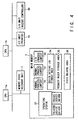
- FIG. 4 is a schematic view showing a computer system according to the first embodiment.
- the computer system of this embodiment comprises CPUs 1a and 1b, a memory state recovery unit 2, a main memory 3, and I/O devices 4a and 4b such as a printer and an RS232C controller.
- the memory state recovery unit 2 holds the before image to restore the contents of the main memory 3.
- a detail of a memory state recovery unit 2 is described in C. Kubiak et al., PENELOPE: A RECOVERY MECHANISM FOR TRANSIENT HARDWARE FAILURES AND SOFTWARE ERRORS, FTCS, 1982.
- the context of an application process including a stack area and data area is stored in the main memory 3 as context information 31.
- an application process means a process of a conventional computer system.
- the operating system 33 more specifically the printer device driver and RS232C device driver sets up operation mode such as a baud rate, a stop bit, a parity, and the like when the system is initialized or an application process requests.
- the set up operation mode is stored in a state setting storage area 34 as log data.
- state set up sequence to an I/O device such as an RS232C controller is performed by a device driver routine named xxconfig, the interface of which is common to all the device drivers. Therefore, the parameters of the config routine is preferably stored in the state setting storage area 34 of the main memory 3 at the entry of the config routine, and the parameters of the config routine can be recorded in the same way not depending on the I/O device type.
- FIG. 5 shows a flow diagram of a config routine for each I/O device.
- FIG. 6 shows a flow diagram of a checkpoint acquisition.
- FIG. 7 shows a flow diagram when the set up sequence is replayed from the most recent checkpoint upon occurrence of a fault.
- a state holding area 36 is effectively arranged in the main memory 3 to manage the state setting flags of the I/O devices 4a and 4b.
- the state setting up flags are managed in the following manner.
- the state setting up flag ON indicates that some state setting up sequence has been performed or being performed to the I/O device since the most recent checkpoint, and the state setting up flag OFF indicates that no state setting has been performed to the I/O device since the most recent checkpoint.
- FIG. 8 shows a flow diagram of a config routine in case the above state setting up flags are employed.
- FIG. 9 shows a flow diagram of a checkpoint acquisition in this case.
- FIG. 10 shows a flow diagram for fault recovery in this case.
- the fault recovery can skip initializing an I/O device with the recovery setting up flag OFF, which results in faster fault recovery.
- a computer system according to this embodiment comprises, in addition to the arrangement of the computer system described in the first embodiment, an arrangement having a request block storage area 35 and I/O execution processes (FIG. 4).
- the operating system instead of calling the device driver routine in the context of the caller process, calls a request block create routine.
- the request block create routine creates a request block having the entry address of the device driver routine and the parameters.
- the application (caller) process moves to wait state.
- the request block is simply held in the main memory until a new checkpoint is acquired. Therefore, if there are a lot of application processes in the computer system, the number of the request blocks held in the main memory would increase as time goes.
- An I/O execution process is a special process to execute device driver routines according to a request block.
- the request blocks become ready to be processed.
- An I/O execution process with initial state is allocated to one of the request blocks.
- the I/O execution process executes the device driver routine with the appropriate parameters both of which are designated by the request block. Therefore, the number of I/O operations being performed concurrently depends on the number of I/O execution processes.
- the I/O execution process moves into wait state when it invokes the I/O device within the designated device driver routine.
- the I/O device returns a termination interrupt
- the interrupt handling routine of the device driver is called and the result is reflected to the I/O execution process context. Then, the I/O execution process turns ready.
- the I/O execution process reports the result to the application process via the request block.
- an in-operation flag is employed for each I/O unit with DMA capability in order to determine whether each I/O device must be initialized or not.
- An in-operation flag is controlled to be ON only while the corresponding I/O device performs DMA transfer.
- FIG. 11 shows an I/O request flow diagram performed by an application process in this embodiment.
- FIG. 12 shows a flow diagram of an I/O execution process. Here, it is assumed that a multiplicity of I/O execution processes are executed concurrently.
- FIGS. 13A through 13D show a sample sequence of I/O operations performed by two application processes and two I/O execution processes.
- a corresponding request block is created and stored in the memory.
- an I/O execution process register setting up, starting, and completion interrupt processing of the I/O device
- I/O execution process context FIGGS. 13C and 13D.
- FIG. 14 shows a flow diagram of checkpoint acquisition in this embodiment.
- FIG. 15 shows a flow diagram of a fault recovery upon occurrence of a fault in this embodiment.
- initialization at step J4 can be performed without any influence on the application process which requested the I/O operation.
- the above initialization would need a much complicated or ad hoc process.
- This execution permission flag is controlled such that the execution permission flag remains OFF until a new checkpoint is acquired, and is turned ON when a new checkpoint has been acquired.
- FIG. 16 shows a flow diagram performed by an application process when the execution permission flag is added.
- FIG. 17 shows a flow diagram of an I/O execution process. In this case, it is assumed that a multiplicity of I/O execution processes are executed concurrently.
- FIG. 18 shows a flow diagram of a checkpoint acquisition.
- FIGS. 19A through 19E show how the I/O requests are performed. Here, two application processes, a checkpoint acquisition, and two I/O execution processes are related.
- FIG. 20 shows a flow diagram of a fault recovery and re-execution of an I/O operation.
- the CPU which executed an application process which made an I/O request should be assigned to the I/O execution process which is responsible for the request block created by the I/O request.
- a preferable embodiment is as follows.
- a request block has a CPU identifier field.
- the identifier of the CPU which executes the application process is written into the CPU identifier field.
- An I/O execution process takes a request block having the same CPU identifier with the CPU which executes the I/O execution process.
- the number of CPUs which are assigned to the I/O execution processes should be determined according to the number of the executable request blocks and the number of CPUs of the computer. If the number of the executable request blocks increases, more CPUs should be assigned to the I/O execution processes.
- One preferable embodiment is that the scheduler of the computer determines whether an idle state CPU is assigned to an application process or an I/O execution process depending on the number of executable request blocks.
- a computer system comprises, in addition to the arrangement of the computer system described in the second embodiment, a state holding area 36.
- an I/O device such as a printer.
- the slip may be left in an incomplete state (i.e., the printer cannot be restored to the state of the most recent checkpoint or finish printing the slip completely.)
- an execution interruption error flag is added to a request block in this embodiment. This execution interruption error flag is used to identify whther the I/O opera tion designated by a request block results in an unrecoverable I/O error by a fault occurrence in the computer system.
- FIG. 21 shows a flow diagram performed by an application process in this embodiment.
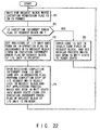
- FIG. 22 shows a flow diagram of an I/O execution process.
- FIG. 23 shows a flow diagram of a checkpoint acquisition in this embodiment.
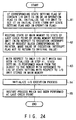
- FIG. 24 shows a flow diagram of a fault recovery upon occurrence of a fault in this embodiment.
- the execution interruption error flag is ON and it remains unchanged through the main memory restoration. Then an I/O execution process tries to re-execute the request block and it finds the execution interruption error flag is ON (at step P2).
- the I/O execution process instead of re-executing the I/O operation, sets an error code in the result code field of the request block, and sets the application process into ready state.
- the execution interruption error flag is a ternary flag, i.e., completion/in-execution/non-execution.
- FIG. 25 shows a flow diagram performed by an application process in this case.
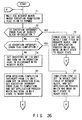
- FIG. 26 shows a flow diagram of an I/O execution process.
- the execution interruption error flag is completion and it remains unchanged through the main memory restoration. Then an I/O execution process tries to re-execute the request block and it finds the execution interruption error flag shows completion (at step T3).
- the I/O execution process instead of re-executing the I/O operation, sets a termination code in the result code field of the request block, and sets the application process into a ready state.
Landscapes
- Engineering & Computer Science (AREA)
- Theoretical Computer Science (AREA)
- Quality & Reliability (AREA)
- Physics & Mathematics (AREA)
- General Engineering & Computer Science (AREA)
- General Physics & Mathematics (AREA)
- Retry When Errors Occur (AREA)
Claims (33)
- E/A-Steuervorrichtung bei einem Computersystem, die eine oder mehrere CPUs (1a, 1b), einen Hauptspeicher (3) und eine oder mehrere E/A-Vorrichtungen (4a, 4b) aufweist, wobei die CPUs periodisch den internen Zustand der CPUs und den Inhalt des Hauptspeichers als einen Prüfpunkt speichern, und der interne Zustand der CPUs und der Inhalt des Hauptspeichers des allerletzten Prüfpunkts wieder hergestellt werden, wenn ein Fehler in dem Computersystem auftritt, um die Datenverarbeitung neu zu starten, gekennzeichnet durch:ein E/A-Vorrichtungszustands-Speichermittel (34, A1, A2, 1a) in dem Hauptspeicher zum Speichern von Protokolldaten der Zustandseinstellungen der E/A-Vorrichtung, die von den CPUs durchgeführt wurden, einschließlich einer Betriebsart mit Bezug auf die E/A-Vorrichtungen; undein E/A-Vorrichtungszustands-Wiederherstellungsmittel (1a, C1, C2, C3) zum Wiederherstellen des Zustands der E/A-Vorrichtungen auf denjenigen des allerletzten Prüfpunkts, wobei zuerst die E/A-Vorrichtungen initialisiert und zweitens die Zustandseinstellsequenz gemäß den durch das E/A-Vorrichtungszustands-Speichermittel gespeicherten Protokolldaten wiedergegeben wird.
- Vorrichtung gemäß Anspruch 1, dadurch gekennzeichnet, dass das Speichermittel ein Mittel (1a, C2) zum Löschen eines Teils der existierenden Protokolldaten umfasst, die durch Einstellen der neuen Zustände unnötig werden.
- Vorrichtung gemäß Anspruch 1, dadurch gekennzeichnet, dass das E/A-Vorrichtungszustands-Wiederherstellungsmittel ein Mittel (1a, F1) zum Überspringen der Initialisierungsund Wiedergabe-Zustandseinstellsequenz der E/A-Vorrichtung umfasst, wenn keine neuen Zustandseinstellungen seit dem letzten Prüfpunkt durchgeführt wurden.
- Vorrichtung gemäß Anspruch 1, ferner gekennzeichnet durch:ein Anforderungsblock-Erzeugungsmittel (35) zum Erzeugen, wenn ein Anwendungsprozess in dem Computersystem eine E/A-Anforderung durchführt, eines Anforderungsblocks in dem Hauptspeicher, der Information enthält, die zum Durchführen der E/A-Anforderung notwendig ist;ein E/A-Ausführungsprozess (32, Fig. 4, H1, H2, H3 in Fig. 12) zum Durchführen eines E/A-Vorgangs durch Ausführen von E/A-Vorrichtungstreiberroutinen gemäß einem Anforderungsblock;ein E/A-Ausführungsprozess-Initialisierungsmittel (J4 in Fig. 15) zum Initialisieren beim Neustarten von dem allerletzten Prüfpunkt nach dem Auftreten eines Fehlers der sich nicht im Anfangszustand befindlichen E/A-Ausführungsprozesse und Veranlassen, dass E/A-Vorgänge, die von den E/A-Ausführungsprozessen durchzuführen sind, erneut vom Anfang durchgeführt werden.
- Vorrichtung gemäß Anspruch 2, ferner gekennzeichnet durch:ein Anforderungsblock-Erzeugungsmittel (35) zum Erzeugen, wenn ein Anwendungsprozess in dem Computersystem eine E/A-Anforderung durchführt, eines Anforderungsblocks in dem Hauptspeicher, der die Information enthält, die zum Durchführen der E/A-Anforderung notwendig ist;E/A-Ausführungsprozesse (32, Fig. 4, H1, H2, H3 in Fig. 12) zum Durchführen eines E/A-Vorgangs durch Ausführen von E/A-Vorrichtungstreiberroutinen gemäß einem Anforderungsblock;ein E/A-Ausführungsprozess-Initialisierungsmittel (J4 in Fig. 15) zum Initialisieren bei einem Neustart von dem letzten Prüfpunkt nach dem Auftreten eines Fehlers der sich nicht im Anfangszustand befindlichen E/A-Ausführungsprozesse und Veranlassen, dass E/A-Vorgänge, die von den E/A-Ausführungsprozessen durchzuführen sind, erneut vom Anfang durchgeführt werden.
- Vorrichtung gemäß Anspruch 3, ferner gekennzeichnet durch:ein Anforderungsblock-Erzeugungsmittel (35) zum Erzeugen, wenn ein Anwendungsprozess in dem Computersystem eine E/A-Anforderung durchführt, eines Anforderungsblocks in dem Hauptspeicher, der Information enthält, die zum Durchführen der E/A-Anforderung notwendig ist;E/A-Ausführungsprozesse (32, Fig. 4, H1, H2, H3 in Fig. 12) zum Durchführen eines E/A-Vorgangs durch Ausführen von E/A-Vorrichtungstreiberroutinen gemäß einem Anforderungsblock;E/A-Ausführungsprozess-Initialisierungsmittel (J4 in Fig. 15) zum Initialisieren beim Neustarten von dem letzten Prüfpunkt nach dem Auftreten eines Fehlers der sich nicht im Anfangszustand befindlichen E/A-Ausführungsprozesse und Veranlassen, dass E/A-Vorgänge, die von den E/A-Ausführungsvorgängen durchzuführen sind, erneut vom Anfang durchgeführt werden.
- Vorrichtung gemäß Anspruch 4, dadurch gekennzeichnet, dass von den in dem Hauptspeicher gehaltenen Anforderungsblöcken die E/A-Ausführungsprozesse einen E/A-Vorgang gemäß einem vor dem allerletzten Prüfpunkt erzeugten Anforderungsblock beginnen durchzuführen, während die E/A-Ausführungsprozesse einen E/A-Vorgang gemäß einem nach dem letzten Prüfpunkt erzeugten Anforderungsblock bis zu einer neuen Prüfpunkterfassung aufschieben.
- Vorrichtung gemäß Anspruch 5, dadurch gekennzeichnet, dass von den in dem Hauptspeicher gehaltenen Anforderungsblöcken die E/A-Ausführungsprozesse einen E/A-Vorgang gemäß einem vor dem allerletzten Prüfpunkt erzeugten Anforderungsblock beginnen durchzuführen, während die E/A-Ausführungsprozesse einen E/A-Vorgang gemäß einem nach dem letzten Prüfpunkt erzeugten Anforderungsblock bis zu einer neuen Prüfpunkterfassung verschieben.
- Vorrichtung gemäß Anspruch 6, dadurch gekennzeichnet, dass von den in dem Hauptspeicher gehaltenen Anforderungsblöcken die E/A-Ausführungsprozesse einen E/A-Vorgang gemäß einem vor dem allerletzten Prüfpunkt erzeugten Anforderungsblock beginnen durchzuführen, während die E/A-Ausführungsprozesse einen E/A-Vorgang gemäß einem nach dem allerletzten Prüfpunkt erzeugten Anforderungsblock bis zu einer neuen Prüfpunkterfassung verschieben.
- Vorrichtung gemäß Anspruch 7, dadurch gekennzeichnet, dass die CPUs den E/A-Ausführungsprozessen zugewiesen werden, wenn eine neue Prüfpunkterfassung abgeschlossen wurde.
- Vorrichtung gemäß Anspruch 8, dadurch gekennzeichnet, dass die CPUs den E/A-Ausführungsprozessen zugewiesen werden, wenn eine neue Prüfpunkterfassung abgeschlossen wurde.
- Vorrichtung gemäß Anspruch 9, dadurch gekennzeichnet, dass die CPUs den E/A-Ausführungsprozessen zugewiesen werden, wenn eine neue Prüfpunkterfassung abgeschlossen wurde.
- Vorrichtung gemäß Anspruch 4, dadurch gekennzeichnet, dass die CPU, die einen Anwendungsprozess ausführt, der eine E/A-Anforderung durchführte, ebenfalls einen E/A-Ausführungsprozess, der für den erzeugten Anforderungsblock verantwortlich ist, basierend auf der E/A-Anforderung ausführt.
- Vorrichtung gemäß Anspruch 5, dadurch gekennzeichnet, dass die CPU, die einen Anwendungsprozess ausführt, der eine E/A-Anforderung durchführte, ebenfalls einen E/A-Ausführungsprozess, der für den erzeugten Anforderungsblock verantwortlich ist, basierend auf der E/A-Anforderung ausführt.
- Vorrichtung gemäß Anspruch 6, dadurch gekennzeichnet, dass die CPU, die einen Anwendungsprozess ausführt, der eine E/A-Anforderung durchführte, ebenfalls einen E/A-Ausführungsprozess, der für den erzeugten Anforderungsblock verantwortlich ist, basierend auf der E/A-Anforderung ausführt.
- Vorrichtung gemäß Anspruch 4, dadurch gekennzeichnet, dass die Anzahl von CPUs, die den E/A-Ausführungsprozessen zugewiesen sind, abhängig von der Anzahl zu verarbeitender Anforderungsblöcke bestimmt wird.
- Vorrichtung gemäß Anspruch 5, dadurch gekennzeichnet, dass die Anzahl von CPUs, die den E/A-Ausführungsprozessen zugewiesen sind, abhängig von der Anzahl zu verarbeitender Anforderungsblöcke bestimmt wird.
- Vorrichtung gemäß Anspruch 6, dadurch gekennzeichnet, dass die Anzahl von CPUs, die den E/A-Ausführungsprozessen zugewiesen sind, abhängig von der Anzahl zu verarbeitender Anforderungsblöcke bestimmt wird.
- Vorrichtung gemäß Anspruch 4, ferner gekennzeichnet durch ein Mittel (P2 in Fig. 22) zum Erzeugen einer Fehlerantwort für den Anwendungsprozess ohne erneutes Ausführen des angeforderten E/A-Vorgangs wenn ein Fehler auftritt, im Fall, däss es dem E/A-Vorrichtungszustands-Wiederherstellungsmittel nicht gelingt, den Zustand der E/A-Vorrichtung wieder herzustellen, der sich auf die E/A-Anforderung bezieht.
- Vorrichtung gemäß Anspruch 5, ferner gekennzeichnet durch ein Mittel zum Erzeugen einer Fehlerantwort auf den Anwendungsprozess ohne erneutes Ausführen des angeforderten E/A-Vorgangs wenn ein Fehler auftritt, im Fall, dass es dem E/A-Vorrichtungszustands-Wiederherstellungsmittel nicht gelingt, den Zustand der E/A-Vorrichtung wieder herzustellen, der sich auf die E/A-Anforderung bezieht.
- Vorrichtung gemäß Anspruch 6, ferner gekennzeichnet durch ein Mittel zum Erzeugen einer Fehlerantwort für den Anwendungsprozess ohne erneutes Ausführen des angeforderten E/A-Vorgangs, wenn ein Fehler auftritt, im Fall, dass es dem E/A-Vorrichtungszustands-Wiederherstellungsmittel nicht gelingt, den Zustand der E/A-Vorrichtung wieder herzustellen, der sich auf die E/A-Anforderung bezieht.
- Vorrichtung gemäß Anspruch 7, ferner gekennzeichnet durch ein Mittel zum Erzeugen einer Fehlerantwort für den Anwendungsprozess ohne erneutes Ausführen des angeforderten E/A-Vorgangs, wenn ein Fehler auftritt, im Fall, dass es dem E/A-Vorrichtungszustands-Wiederherstellungsmittel nicht gelingt, den Zustand der E/A-Vorrichtung wieder herzustellen, der sich auf die E/A-Anforderung bezieht.
- Vorrichtung gemäß Anspruch 8, ferner gekennzeichnet durch eines Mittels zum Erzeugen einer Fehlerantwort für den Anwendungsprozess ohne erneutes Ausführen des angeforderten E/A-Vorgangs, wenn ein Fehler auftritt, im Fall, dass es dem E/A-Vorrichtungszustands-Wiederherstellungsmittel nicht gelingt, den Zustand der E/A-Vorrichtung wieder herzustellen, der sich auf die E/A-Anforderung bezieht.
- Vorrichtung gemäß Anspruch 9, ferner gekennzeichnet durch Umfassen eines Mittels zum Erzeugen, wenn ein Fehler auftritt, einer Fehlerantwort auf den Anwendungsprozess ohne erneutes Ausführen des angeforderten E/A-Vorgangs im Fall, dass es dem E/A-Vorrichtungszustands-Wiederherstellungsmittel nicht gelingt, den Zustand der E/A-Vorrichtung wieder herzustellen, der sich auf die E/A-Anforderung bezieht.
- Vorrichtung gemäß Anspruch 4, ferner gekennzeichnet durch ein Mittel zum Erzeugen einer erfolgreichen E/A-Beendigungsantwort für den Anwendungsprozess ohne erneutes Ausführen des angeforderten E/A-Vorgangs, wenn ein Fehler auftritt, in dem Fall, dass die E/A-Anforderung eine Ausgabeanforderung ist und die E/A-Anforderung vor dem Auftreten des Fehlers abgeschlossen wurde.
- Vorrichtung gemäß Anspruch 5, ferner gekennzeichnet durch ein Mittel zum Erzeugen einer erfolgreichen E/A-Beendigungsantwort für den Anwendungsprozess ohne erneutes Ausführen des angeforderten E/A-Vorgangs, wenn ein Fehler auftritt, in dem Fall, dass die E/A-Anforderung eine Ausgabeanforderung ist und die E/A-Anforderung vor dem Auftreten des Fehlers abgeschlossen wurde.
- Vorrichtung gemäß Anspruch 6, ferner gekennzeichnet durch ein Mittel zum Erzeugen einer erfolgreichen E/A-Beendigungsantwort für den Anwendungsprozess ohne erneutes Ausführen des angeforderten E/A-Vorgangs, wenn ein Fehler auftritt, in dem Fall, dass die E/A-Anforderung eine Ausgabeanforderung ist und die E/A-Anforderung vor dem Auftreten des Fehlers abgeschlossen wurde.
- Vorrichtung gemäß Anspruch 7, ferner gekennzeichnet durch ein Mittel zum Erzeugen einer erfolgreichen E/A-Beendigungsantwort für den Anwendungsprozess ohne erneutes Ausführen des angeforderten E/A-Vorgangs, wenn ein Fehler auftritt, in dem Fall, dass die E/A-Anforderung eine Ausgabeanforderung ist und die E/A-Anforderung vor dem Auftreten des Fehlers abgeschlossen wurde.
- Vorrichtung gemäß Anspruch 8, ferner gekennzeichnet durch ein Mittel zum Erzeugen einer erfolgreichen E/A-Beendigungsantwort an den E/A-Anforderungsprozess ohne erneutes Ausführen des angeforderten E/A-Vorgangs, wenn ein Fehler des Computersystems auftritt, in dem Fall, dass die E/A-Anforderung eine Ausgabeanforderung ist und die E/A-Anforderung vor dem Auftreten des Fehlers abgeschlossen wurde.
- Vorrichtung gemäß Anspruch 9, ferner gekennzeichnet durch ein Mittel zum Erzeugen einer erfolgreichen E/A-Beendigungsantwort auf den Anwendungsprozess ohne erneutes Ausführen des angeforderten E/A-Vorgangs, wenn ein Fehler auftritt, in dem Fall, dass die E/A-Anforderung eine Ausgabeanforderung ist und die E/A-Anforderung vor dem Auftreten des Fehlers abgeschlossen wurde.
- E/A-Steuerverfahren bei einem Computersystem, das eine oder mehrere CPUs, einen Hauptspeicher und eine oder mehrere E/A-Vorrichtungen aufweist, wobei die CPUs periodisch den internen Zustand der CPUs und den Inhalt des Hauptspeichers als einen Prüfpunkt speichern, und der interne Zustand der CPUs und der Inhalt des Hauptspeichers des letzten Prüfpunkts wieder hergestellt wird, wenn ein Fehler in dem Computersystem auftritt, um die Datenverarbeitung erneut zu starten, gekennzeichnet durch:Speichern (A1 in Fig. 5) in dem Hauptspeicher von Protokolldaten von Zustandseinstellungen der E/A-Vorrichtungen, die von den CPUs durchgeführt wurden einschließlich einer Betriebsart mit Bezug auf die E/A-Vorrichtungen; undWiederherstellen (B1 in Fig. 6) des Zustands der E/A-Vorrichtungen auf denjenigen des letzten Prüfpunkts, wobei zuerst die E/A-Vorrichtungen initialisiert werden und zweitens die Zustandseinstellsequenz gemäß den durch das E/A-Vorrichtungszustands-Speichermittel gespeicherten Protokolldaten wiedergegeben werden.
- Massenprodukt mit:einem Computer-verwendbaren Medium mit Computer-lesbaren Programm-Codemitteln, die darin aufgenommen sind, um zu veranlassen, dass die Zustände von Eingabe- und Ausgabe-Einheiten (E/A-Einheiten) auf jeweilige Prüfpunkte wieder hergestellt werden, wenn ein Computersystem beim Auftreten eines Fehlers neu gestartet wird, wobei das Computersystem eine oder mehrere CPUs, einen Hauptspeicher und eine oder mehrere E/A-Vorrichtungen aufweist und periodisch den internen Zustand der CPUs und den Inhalt des Hauptspeichers als einen Prüfpunkt speichert, und der interne Zustand der CPUs und der Inhalt des Hauptspeichers des allerletzten Prüfpunkts wieder hergestellt wird, wenn ein Fehler in dem Computersystem auftritt, um die Datenverarbeitung neu zu starten, wobei die Computer-lesbaren Programm-Codemittel in dem Massenprodukt umfassen:ein Computer-lesbares Programm-Codemittel, um einen Computer zu veranlassen, Protokolldaten von Zustandseinstellungen der E/A-Einheiten in dem Hauptspeicher zu speichern, einschließlich einer Betriebsart mit Bezug auf die E/A-Vorrichtungen, undein Computer-lesbares Programm-Codemittel, um einen Computer zu veranlassen, die E/A-Vorrichtungen zu initialisieren und Zustandseinstellungen der E/A-Vorrichtungen in Übereinstimmung mit den gespeicherten Protokolldaten bei Auftreten eines Fehlers in dem Computersystem einzustellen.
- Massenprodukt mit:einem Computer-verwendbaren Medium mit Computer-lesbaren Programm-Codemitteln, die darin aufgenommen sind, um zu veranlassen, dass die Zustände von Eingabe- und Ausgabe-Einheiten (E/A-Einheiten) auf jeweilige Prüfpunkte wieder hergestellt wird, wenn ein Computersystem beim Auftreten eines Fehlers neu gestartet wird, wobei das Computersystem eine oder mehrere CPUs, einen Hauptspeicher und eine oder mehrere E/A-Vorrichtungen aufweist und periodisch den internen Zustand der CPUs und den Inhalt des Hauptspeichers als einen Prüfpunkt speichert, und der interne Zustand der CPUs und der Inhalt des Hauptspeichers des letzten Prüfpunkts wiederhergestellt wird, wenn ein Fehler in dem Computersystem auftritt, um die Datenverarbeitung neu zu starten, wobei die Computer-lesbaren Programm-Codemittel in dem Massenprodukt umfassen:ein Computer-lesbares Programm-Codemittel, um einen Computer zu veranlassen, Protokolldaten eines Zustands von Einstellungen der E/A-Einheit einschließlich einer Betriebsart mit Bezug auf die E/A-Vorrichtungen in dem Hauptspeicher zu speichern;ein Computer-lesbares Programm-Codemittel, um einen Computer zu veranlassen, die E/A-Vorrichtungen zu initialisieren und Zustandseinstellungen der E/A-Vorrichtungen in Übereinstimmung mit den gleichen Protokolldaten beim Auftreten eines Fehlers in dem Computersystem einzustellen;ein Computer-lesbares Programm-Codemittel, um einen Computer zu veranlassen, wenn ein Prozess in dem Computersystem eine E/A-Anforderung erzeugt, einen Anforderungsblock in dem Hauptspeicher zu erzeugen, der Information enthält, die zum Durchführen der E/A-Anforderung notwendig ist;ein Computer-lesbares Programm-Codemittel, um einen Computer zu veranlassen, einen E/A-Vorgang durch Zugreifen auf die E/A-Vorrichtungen gemäß einem Anforderungsblock durchzuführen;ein Computer-lesbares Programm-Codemittel, um einen Computer zu veranlassen, beim Neustarten von dem letzten Prüfpunkt, der dem Auftreten eines Fehlers folgt, die E/A-Ausführungsprozesse im Ausführungszustand zu initialisieren, und zu veranlassen, dass E/A-Vorgänge, die von dem E/A-Ausführungsprozess durchgeführt werden, die erneut vom Anfang durchzuführen sind.
Applications Claiming Priority (3)
| Application Number | Priority Date | Filing Date | Title |
|---|---|---|---|
| JP1535296 | 1996-01-31 | ||
| JP15352/96 | 1996-01-31 | ||
| JP1535296 | 1996-01-31 |
Publications (2)
| Publication Number | Publication Date |
|---|---|
| EP0788052A1 EP0788052A1 (de) | 1997-08-06 |
| EP0788052B1 true EP0788052B1 (de) | 2002-12-18 |
Family
ID=11886412
Family Applications (1)
| Application Number | Title | Priority Date | Filing Date |
|---|---|---|---|
| EP97100684A Expired - Lifetime EP0788052B1 (de) | 1996-01-31 | 1997-01-17 | Eingabe-/Ausgabesteuergerät mit Wiederanlaufkennzeichnungsfunktion |
Country Status (5)
| Country | Link |
|---|---|
| US (1) | US5931954A (de) |
| EP (1) | EP0788052B1 (de) |
| KR (1) | KR100262835B1 (de) |
| CN (1) | CN1098490C (de) |
| DE (1) | DE69717876T2 (de) |
Families Citing this family (46)
| Publication number | Priority date | Publication date | Assignee | Title |
|---|---|---|---|---|
| JP3253883B2 (ja) * | 1997-01-31 | 2002-02-04 | 株式会社東芝 | プロセスリスタート方法及びプロセス監視装置 |
| US6332199B1 (en) * | 1998-10-29 | 2001-12-18 | International Business Machines Corporation | Restoring checkpointed processes including adjusting environment variables of the processes |
| EP1185928A1 (de) | 1998-12-16 | 2002-03-13 | Kent Ridge Digital Labs | Prozess-orientierte rechner-umgebung |
| US6345331B1 (en) * | 1999-04-20 | 2002-02-05 | International Business Machines Corporation | Device adapter being reintegrated with plurality of device adapters of network, or reestablishing permissions and resubmitting I/O requests depending on determined device state after failure |
| US6490690B1 (en) * | 1999-07-22 | 2002-12-03 | International Business Machines Corporation | Method and apparatus for unix system catastrophic recovery aid |
| US7065779B1 (en) * | 1999-10-13 | 2006-06-20 | Cisco Technology, Inc. | Technique for synchronizing multiple access controllers at the head end of an access network |
| US7639617B2 (en) * | 2001-06-27 | 2009-12-29 | Cisco Technology, Inc. | Upstream physical interface for modular cable modem termination system |
| US7139923B1 (en) | 2001-06-27 | 2006-11-21 | Cisco Technology, Inc. | Technique for synchronizing network devices in an access data network |
| US7209442B1 (en) * | 2001-06-27 | 2007-04-24 | Cisco Technology, Inc. | Packet fiber node |
| US7688828B2 (en) * | 2001-06-27 | 2010-03-30 | Cisco Technology, Inc. | Downstream remote physical interface for modular cable modem termination system |
| US7085287B1 (en) | 2001-06-27 | 2006-08-01 | Cisco Technology, Inc. | Map routing technique implemented in access networks |
| US6883114B2 (en) * | 2001-11-08 | 2005-04-19 | M-Systems Flash Disk Pioneers Ltd. | Block device driver enabling a ruggedized file system |
| KR20030056540A (ko) * | 2001-12-28 | 2003-07-04 | 한국전자통신연구원 | 데이터베이스 관리 시스템에서 시스템 고장에 대비한 파일삭제 및 회복 방법 |
| US7583704B1 (en) | 2003-06-10 | 2009-09-01 | Carl Walker | Synchronizing separated upstream and downstream channels of cable modem termination systems |
| US20050094551A1 (en) * | 2003-09-25 | 2005-05-05 | Broadcom Corporation | Processor instruction for DMT encoding |
| US7305608B2 (en) * | 2003-09-25 | 2007-12-04 | Broadcom Corporation | DSL trellis encoding |
| US7756273B2 (en) * | 2003-09-26 | 2010-07-13 | Broadcom Corporation | System and method for bit-reversing and scrambling payload bytes in an asynchronous transfer mode cell |
| US7903810B2 (en) | 2003-09-26 | 2011-03-08 | Broadcom Corporation | Single instruction for data scrambling |
| US7751557B2 (en) * | 2003-09-26 | 2010-07-06 | Broadcom Corporation | Data de-scrambler |
| US7734041B2 (en) * | 2003-09-26 | 2010-06-08 | Broadcom Corporation | System and method for de-scrambling and bit-order-reversing payload bytes in an Asynchronous Transfer Mode cell |
| US7580412B2 (en) * | 2003-09-26 | 2009-08-25 | Broadcom Corporation | System and method for generating header error control byte for Asynchronous Transfer Mode cell |
| US7216255B2 (en) * | 2004-01-23 | 2007-05-08 | Microsoft Corporation | Adaptive recovery from system failure for application instances that govern message transactions |
| US7646786B2 (en) * | 2004-05-25 | 2010-01-12 | Cisco Technology, Inc. | Neighbor discovery in cable networks |
| US7817553B2 (en) * | 2004-05-25 | 2010-10-19 | Cisco Technology, Inc. | Local area network services in a cable modem network |
| US7539208B2 (en) * | 2004-05-25 | 2009-05-26 | Cisco Technology, Inc. | Timing system for modular cable modem termination system |
| US7864686B2 (en) * | 2004-05-25 | 2011-01-04 | Cisco Technology, Inc. | Tunneling scheme for transporting information over a cable network |
| US7532627B2 (en) * | 2004-05-25 | 2009-05-12 | Cisco Technology, Inc. | Wideband upstream protocol |
| US8102854B2 (en) * | 2004-05-25 | 2012-01-24 | Cisco Technology, Inc. | Neighbor discovery proxy with distributed packet inspection scheme |
| US8149833B2 (en) * | 2004-05-25 | 2012-04-03 | Cisco Technology, Inc. | Wideband cable downstream protocol |
| US7835274B2 (en) * | 2004-05-25 | 2010-11-16 | Cisco Technology, Inc. | Wideband provisioning |
| US7720101B2 (en) * | 2004-05-25 | 2010-05-18 | Cisco Technology, Inc. | Wideband cable modem with narrowband circuitry |
| US7447225B2 (en) * | 2004-07-23 | 2008-11-04 | Cisco Technology, Inc. | Multiple multicast forwarder prevention during NSF recovery of control failures in a router |
| US7340582B2 (en) * | 2004-09-30 | 2008-03-04 | Intel Corporation | Fault processing for direct memory access address translation |
| US20060129618A1 (en) * | 2004-12-10 | 2006-06-15 | Albert Maier | Method and a computer system for synchronising backups of objects and of meta data about the objects |
| JP4060322B2 (ja) * | 2005-03-28 | 2008-03-12 | 三菱電機株式会社 | アプリケーション管理装置およびそのソフトウェアを格納した記憶媒体 |
| US7630361B2 (en) * | 2005-05-20 | 2009-12-08 | Cisco Technology, Inc. | Method and apparatus for using data-over-cable applications and services in non-cable environments |
| KR100755706B1 (ko) * | 2006-01-17 | 2007-09-05 | 삼성전자주식회사 | 애드 혹 네트워크를 위한 분산 서비스 컴포지션 모델을제공하는 방법 및 장치 |
| US7701951B2 (en) * | 2006-03-06 | 2010-04-20 | Cisco Technology, Inc. | Resource reservation and admission control for IP network |
| US8352784B2 (en) * | 2007-12-17 | 2013-01-08 | Microsoft Corporation | Device settings restore point |
| US7979626B2 (en) * | 2008-05-13 | 2011-07-12 | Microsoft Corporation | Flash recovery employing transaction log |
| EP2283331B1 (de) * | 2008-05-23 | 2021-06-30 | Rosemount Inc. | Verbesserte konfiguration einer multivariablen prozessflüssigkeitsflussvorrichtung |
| CN103337113B (zh) * | 2013-07-17 | 2015-05-13 | 广州广电运通金融电子股份有限公司 | 电子流水日志智能分析方法、装置及处理器 |
| US9495242B2 (en) * | 2014-07-30 | 2016-11-15 | International Business Machines Corporation | Adaptive error correction in a memory system |
| US10642536B2 (en) * | 2018-03-06 | 2020-05-05 | Western Digital Technologies, Inc. | Non-volatile storage system with host side command injection |
| EP4100845A4 (de) * | 2020-02-03 | 2024-02-21 | Samsung Electronics Co., Ltd. | Datenverwaltungssystem und verfahren zur steuerung |
| US11636199B2 (en) * | 2021-04-12 | 2023-04-25 | Realtek Singapore Pte Ltd. | Real time clock with integrated anti-rollback protection |
Family Cites Families (9)
| Publication number | Priority date | Publication date | Assignee | Title |
|---|---|---|---|---|
| US3688274A (en) * | 1970-12-23 | 1972-08-29 | Ibm | Command retry control by peripheral devices |
| US3736566A (en) * | 1971-08-18 | 1973-05-29 | Ibm | Central processing unit with hardware controlled checkpoint and retry facilities |
| US4740969A (en) * | 1986-06-27 | 1988-04-26 | Hewlett-Packard Company | Method and apparatus for recovering from hardware faults |
| JPH02294753A (ja) * | 1989-05-09 | 1990-12-05 | Fujitsu Ltd | 入出力処理装置の初期化方式 |
| US5293613A (en) * | 1991-08-29 | 1994-03-08 | International Business Machines Corporation | Recovery control register |
| US5664090A (en) * | 1993-12-15 | 1997-09-02 | Kabushiki Kaisha Toshiba | Processor system and method for maintaining internal state consistency between active and stand-by modules |
| DE69635409T2 (de) * | 1995-03-06 | 2006-07-27 | Intel Corp., Santa Clara | Ein rechnersystem mit unbewachter auf-anfrage-verfügbarkeit |
| US5751939A (en) * | 1995-11-29 | 1998-05-12 | Texas Micro, Inc. | Main memory system and checkpointing protocol for fault-tolerant computer system using an exclusive-or memory |
| US5712971A (en) * | 1995-12-11 | 1998-01-27 | Ab Initio Software Corporation | Methods and systems for reconstructing the state of a computation |
-
1997
- 1997-01-13 US US08/782,077 patent/US5931954A/en not_active Expired - Fee Related
- 1997-01-17 DE DE69717876T patent/DE69717876T2/de not_active Expired - Fee Related
- 1997-01-17 EP EP97100684A patent/EP0788052B1/de not_active Expired - Lifetime
- 1997-01-28 CN CN97102091A patent/CN1098490C/zh not_active Expired - Fee Related
- 1997-01-31 KR KR1019970003176A patent/KR100262835B1/ko not_active Expired - Fee Related
Also Published As
| Publication number | Publication date |
|---|---|
| CN1165344A (zh) | 1997-11-19 |
| EP0788052A1 (de) | 1997-08-06 |
| CN1098490C (zh) | 2003-01-08 |
| DE69717876T2 (de) | 2003-11-13 |
| KR100262835B1 (ko) | 2000-08-01 |
| KR970059930A (ko) | 1997-08-12 |
| DE69717876D1 (de) | 2003-01-30 |
| US5931954A (en) | 1999-08-03 |
Similar Documents
| Publication | Publication Date | Title |
|---|---|---|
| US5931954A (en) | I/O control apparatus having check recovery function | |
| JP3675802B2 (ja) | 計算の状態を再構成する方法ならびにシステム | |
| US7840768B2 (en) | Memory-controller-embedded apparatus and procedure for achieving system-directed checkpointing without operating-system kernel support | |
| US5802267A (en) | Method for checkpointing in computer system under distributed processing environment | |
| EP0900420B1 (de) | Hauptspeichervorrichtung und wiederanlaufkennzeichnungsprotokoll für ein fehlertolerantes rechnersystem mit einem lese-pufferspeicher | |
| US5751939A (en) | Main memory system and checkpointing protocol for fault-tolerant computer system using an exclusive-or memory | |
| EP0750259B1 (de) | Rechnersystem mit Zwei-Phasen-Kontrollpunkten | |
| US20090182956A1 (en) | Method and apparatus for improving transactional memory commit latency | |
| US20050246587A1 (en) | Method and system of determining whether a user program has made a system level call | |
| US20060150010A1 (en) | Memory-controller-embedded apparatus and procedure for achieving system-directed checkpointing without operating-system kernel support | |
| JPS638835A (ja) | 障害回復方法 | |
| JPH09258995A (ja) | 計算機システム | |
| US7426656B2 (en) | Method and system executing user programs on non-deterministic processors | |
| CN114756355B (zh) | 一种计算机操作系统的进程自动快速恢复的方法和装置 | |
| US20050246578A1 (en) | Method and system of exchanging information between processors | |
| JP3135714B2 (ja) | チェックポイントリスタート方式 | |
| JPH0644252B2 (ja) | プログラムの動的制御システムおよびその方法 | |
| JP3093653B2 (ja) | 計算機システムの入出力制御装置、及び入出力制御方法 | |
| JP2000222232A (ja) | 電子計算機及び電子計算機のメモリ障害回避方法 | |
| JPH10240635A (ja) | 計算機システムおよびそのシステムにおけるi/o装置の状態復元方法 | |
| JP2671160B2 (ja) | 例外処理方式 | |
| USRE45632E1 (en) | Memory-controller-embedded apparatus and procedure for achieving system-directed checkpointing without operating-system kernel support | |
| US7890798B1 (en) | Computer cluster with second-node instance of application having access to state snapshot of first-node instance of application | |
| JPH10240620A (ja) | コンピュータシステムおよび同システムにおけるチェックポイントイメージ保存方法 | |
| JP3729573B2 (ja) | 並列処理システムの処理引き継ぎ方法 |
Legal Events
| Date | Code | Title | Description |
|---|---|---|---|
| PUAI | Public reference made under article 153(3) epc to a published international application that has entered the european phase |
Free format text: ORIGINAL CODE: 0009012 |
|
| 17P | Request for examination filed |
Effective date: 19970214 |
|
| AK | Designated contracting states |
Kind code of ref document: A1 Designated state(s): DE FR GB |
|
| GRAG | Despatch of communication of intention to grant |
Free format text: ORIGINAL CODE: EPIDOS AGRA |
|
| 17Q | First examination report despatched |
Effective date: 20020415 |
|
| GRAG | Despatch of communication of intention to grant |
Free format text: ORIGINAL CODE: EPIDOS AGRA |
|
| GRAH | Despatch of communication of intention to grant a patent |
Free format text: ORIGINAL CODE: EPIDOS IGRA |
|
| GRAH | Despatch of communication of intention to grant a patent |
Free format text: ORIGINAL CODE: EPIDOS IGRA |
|
| GRAA | (expected) grant |
Free format text: ORIGINAL CODE: 0009210 |
|
| AK | Designated contracting states |
Kind code of ref document: B1 Designated state(s): DE FR GB |
|
| REG | Reference to a national code |
Ref country code: GB Ref legal event code: FG4D |
|
| REF | Corresponds to: |
Ref document number: 69717876 Country of ref document: DE Date of ref document: 20030130 Kind code of ref document: P Ref document number: 69717876 Country of ref document: DE Date of ref document: 20030130 |
|
| ET | Fr: translation filed | ||
| PLBE | No opposition filed within time limit |
Free format text: ORIGINAL CODE: 0009261 |
|
| STAA | Information on the status of an ep patent application or granted ep patent |
Free format text: STATUS: NO OPPOSITION FILED WITHIN TIME LIMIT |
|
| 26N | No opposition filed |
Effective date: 20030919 |
|
| PGFP | Annual fee paid to national office [announced via postgrant information from national office to epo] |
Ref country code: DE Payment date: 20070111 Year of fee payment: 11 |
|
| PGFP | Annual fee paid to national office [announced via postgrant information from national office to epo] |
Ref country code: GB Payment date: 20070117 Year of fee payment: 11 |
|
| REG | Reference to a national code |
Ref country code: GB Ref legal event code: 746 Effective date: 20070317 |
|
| PGFP | Annual fee paid to national office [announced via postgrant information from national office to epo] |
Ref country code: FR Payment date: 20070109 Year of fee payment: 11 |
|
| GBPC | Gb: european patent ceased through non-payment of renewal fee |
Effective date: 20080117 |
|
| PG25 | Lapsed in a contracting state [announced via postgrant information from national office to epo] |
Ref country code: DE Free format text: LAPSE BECAUSE OF NON-PAYMENT OF DUE FEES Effective date: 20080801 |
|
| REG | Reference to a national code |
Ref country code: FR Ref legal event code: ST Effective date: 20081029 |
|
| PG25 | Lapsed in a contracting state [announced via postgrant information from national office to epo] |
Ref country code: GB Free format text: LAPSE BECAUSE OF NON-PAYMENT OF DUE FEES Effective date: 20080117 |
|
| PG25 | Lapsed in a contracting state [announced via postgrant information from national office to epo] |
Ref country code: FR Free format text: LAPSE BECAUSE OF NON-PAYMENT OF DUE FEES Effective date: 20080131 |