EP0788010A1 - Polarization-independent acousto-optical tunable filter - Google Patents
Polarization-independent acousto-optical tunable filter Download PDFInfo
- Publication number
- EP0788010A1 EP0788010A1 EP97300363A EP97300363A EP0788010A1 EP 0788010 A1 EP0788010 A1 EP 0788010A1 EP 97300363 A EP97300363 A EP 97300363A EP 97300363 A EP97300363 A EP 97300363A EP 0788010 A1 EP0788010 A1 EP 0788010A1
- Authority
- EP
- European Patent Office
- Prior art keywords
- light beam
- optical
- walk
- crystal
- waveguide
- Prior art date
- Legal status (The legal status is an assumption and is not a legal conclusion. Google has not performed a legal analysis and makes no representation as to the accuracy of the status listed.)
- Withdrawn
Links
- 230000010287 polarization Effects 0.000 title claims abstract description 67
- 230000003287 optical effect Effects 0.000 claims abstract description 160
- 239000013078 crystal Substances 0.000 claims abstract description 106
- 230000009977 dual effect Effects 0.000 claims description 33
- 239000000463 material Substances 0.000 claims description 18
- 230000001902 propagating effect Effects 0.000 claims description 16
- 238000000926 separation method Methods 0.000 claims description 9
- 239000000382 optic material Substances 0.000 claims description 4
- 238000001914 filtration Methods 0.000 abstract description 18
- 239000000758 substrate Substances 0.000 abstract description 17
- 239000013307 optical fiber Substances 0.000 description 8
- 230000008878 coupling Effects 0.000 description 5
- 238000010168 coupling process Methods 0.000 description 5
- 238000005859 coupling reaction Methods 0.000 description 5
- 238000010897 surface acoustic wave method Methods 0.000 description 4
- 238000006243 chemical reaction Methods 0.000 description 3
- 229910003327 LiNbO3 Inorganic materials 0.000 description 2
- RTAQQCXQSZGOHL-UHFFFAOYSA-N Titanium Chemical compound [Ti] RTAQQCXQSZGOHL-UHFFFAOYSA-N 0.000 description 2
- 230000008901 benefit Effects 0.000 description 2
- 239000000835 fiber Substances 0.000 description 2
- 238000003384 imaging method Methods 0.000 description 2
- GQYHUHYESMUTHG-UHFFFAOYSA-N lithium niobate Chemical compound [Li+].[O-][Nb](=O)=O GQYHUHYESMUTHG-UHFFFAOYSA-N 0.000 description 2
- 238000004519 manufacturing process Methods 0.000 description 2
- 230000010363 phase shift Effects 0.000 description 2
- 229910052719 titanium Inorganic materials 0.000 description 2
- 239000010936 titanium Substances 0.000 description 2
- 239000004593 Epoxy Substances 0.000 description 1
- 238000010276 construction Methods 0.000 description 1
- 239000011521 glass Substances 0.000 description 1
- 230000001939 inductive effect Effects 0.000 description 1
- 238000002955 isolation Methods 0.000 description 1
- 230000001629 suppression Effects 0.000 description 1
Images


Classifications
-
- G—PHYSICS
- G02—OPTICS
- G02F—OPTICAL DEVICES OR ARRANGEMENTS FOR THE CONTROL OF LIGHT BY MODIFICATION OF THE OPTICAL PROPERTIES OF THE MEDIA OF THE ELEMENTS INVOLVED THEREIN; NON-LINEAR OPTICS; FREQUENCY-CHANGING OF LIGHT; OPTICAL LOGIC ELEMENTS; OPTICAL ANALOGUE/DIGITAL CONVERTERS
- G02F1/00—Devices or arrangements for the control of the intensity, colour, phase, polarisation or direction of light arriving from an independent light source, e.g. switching, gating or modulating; Non-linear optics
- G02F1/01—Devices or arrangements for the control of the intensity, colour, phase, polarisation or direction of light arriving from an independent light source, e.g. switching, gating or modulating; Non-linear optics for the control of the intensity, phase, polarisation or colour
- G02F1/11—Devices or arrangements for the control of the intensity, colour, phase, polarisation or direction of light arriving from an independent light source, e.g. switching, gating or modulating; Non-linear optics for the control of the intensity, phase, polarisation or colour based on acousto-optical elements, e.g. using variable diffraction by sound or like mechanical waves
- G02F1/125—Devices or arrangements for the control of the intensity, colour, phase, polarisation or direction of light arriving from an independent light source, e.g. switching, gating or modulating; Non-linear optics for the control of the intensity, phase, polarisation or colour based on acousto-optical elements, e.g. using variable diffraction by sound or like mechanical waves in an optical waveguide structure
Definitions
- This invention relates generally to optical filters and receivers.
- it relates to microphotonic polarization independent acoustic-optical tunable filters.
- An acousto-optic filter is an electronically tunable optical bandpass filter.
- Electronically tunable optical filters have been constructed so that an incident light beam of a first polarization is diffracted by an acoustic wave in a birefringent crystal to shift from the first polarization to a second polarization of the light beam for a selected bandpass of optical frequencies.
- the center wavelength of the passband of this type of filter is electronically tunable by changing the frequency of the acoustic wave within the crystal.
- Bulk AOTF's fabricated in bulk crystals and using bulk acoustic waves and unguided optical beams have already found many important applications in laser and optics systems.
- Integrated AOTFs in which light is confined to a waveguide and which use surface acoustic waves are also expected to find important applications in laser and fiber optics systems, especially such as are used in modern telecommunications applications.
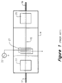
- an integrated AOTF is fabricated in an elongated crystalline substrate 11 such as lithium niobate (LiNbO 3 ).
- An optical waveguide 13 is formed in an upper surface of the substrate, for example by indiffusion of titanium.
- a beam of light is coupled into the waveguide 13 through an input optical fiber 17.
- the light propagates through the waveguide and out through an output optical fiber 19.
- a surface acoustic wave is induced in the waveguide by an interdigitated transducer 21.
- the transducer is driven by an externally-generated electrical signal from a signal source 22.
- the frequency of the acoustic wave is determined by the frequency of the electrical signal.
- the acoustic wave induces a diffraction grating in the waveguide.
- the grating couples the transverse electric (TE) and transverse magnetic (TM) polarization modes of the light, but only within a narrow band of optical wavelengths. Thus, within this narrow band all the light propagating in one polarization mode is converted to the orthogonal mode, whereas outside this band the polarization mode of the light is unaffected
- a TE pass polarizer 23 adjacent the first extremity of the waveguide blocks any incoming light that is not in a first polarization mode. Thus, only light polarized in the first mode is admitted to the filter. As the light travels through the waveguide, the polarization mode of any of the light having a wavelength within the narrow band of optical wavelengths is converted to a second mode which is orthogonal to the first mode. The polarization of the rest of the light is unaffected.
- a TM pass polarizer 25 opposite the polarizer 23 blocks from the output any light that is not in the second polarization mode. Thus, only light having a polarization mode that has been converted while passing through the filter is allowed to exit the filter. No output destination is shown, but it will be understood that the output light is ultimately provided to a user or to an optical device of some type.
- the AOTF passes light having a wavelength within the band determined by the acoustic wave and blocks other light.
- the AOTF serves as a bandpass filter.
- the center frequency of the pass band can be tuned by changing the frequency of the electrical signal that drives the transducer.
- the filter can be converted into a "notch" filter by changing the polarizer 25 to the same type of polarizer as the polarizer 23.
- the frequency of the light is Doppler-shifted because the grating induced by the acoustic wave is in motion with respect to the waveguide. If desired, this Doppler shift can be canceled by passing the light through a second AOTF.
- Figure 2 shows a prior art attempt to fabricate a polarization independent AOTF on a single substrate.
- a first optical waveguide 23 and a second optical waveguide 24 are formed on the upper surface of the substrate.
- a light beam of arbitrary polarization is coupled into the first waveguide 23 and the second waveguide 24 through an input TE-TM splitter 20.
- the TE-TM splitter 20 separates the TE and TM components of the incoming beam of light.
- the TE component is coupled into the first waveguide 23 and the TM component is coupled into the second waveguide 24.
- a surface acoustic wave is induced in the waveguides 23, 24 by an interdigitated transer 21.
- TE-TM splitter 24 combines the TM components within the first waveguide and the TE components of the second waveguide. The combined signals are passed to the output of the AOTF.
- the prior art tunable band-pass filter shown in Figure 2 has very limited out-of-band rejection.
- the TE-TM splitters 20, 24 are very hard to manufacture on the same substrate as the waveguides 23, 24. As a result, the isolation between the TE component coupled into the first waveguide 23 and the TM component coupled into the second waveguide 24 is very poor.
- An ideal TE-TM splitter will not have significant coupling between splitter outputs. That is, the TE component output of the ideal TE-TM splitter will not have a significant TM component and the TM component output of the ideal TE-TM splitter will not have a significant TE component.
- the coupling between the splitter outputs significantly reduces the effectiveness of the out-of band rejection of the filter.
- AOTF construction as has been described is limited because the input beam of light must be constrained to a single polarization in order to obtain useable filter performance. In some applications, it is desirable to be able to filter a beam of light without constraining the incident light to a single polarization.
- a single fiber may couple several optical signals each at a different wavelength and each having a unique polarity to a single AOTF. It would be useful to be able to tune the pass band of the AOTF to be centered on a single one of the optical signals. It would also be useful if the AOTF were able to filter each optical signal individually without requiring the optical signals to be ofa particular polarization.
- the present invention is an AOTF system that is polarization independent and which has filtering characteristics superior to those presently available.
- the invention includes several AOTF system configurations in which each configuration provides a unique set of characteristics.
- a first embodiment of this invention is a polarization independent acousto-optical tunable filter which includes a first walk-off crystal receiving an incoming beam of randomly polarized light and separating the randomly polarized light into a first polarized light beam and a second polarized light beam in which the first light beam and the second light beam are orthogonal to each other and separated by a separation distance.
- This embodiment further includes a dual acousto-optical tunable filter.
- the dual acousto-optical tunable filter includes a base of acousto-optic material comprising a first waveguide and a second waveguide separated by the separation distance and adapted to receive the first light beam and the second light beam, a first transducer responsive to an electrical signal to induce an acoustic wave in the base, the acoustic wave operable to change the polarization mode of any light propagating through the base and having a frequency within an optical frequency band defined by the frequency of the acoustic wave and the optical properties of the base but not to change the polarization mode of any light having a frequency outside the optical frequency band, and providing a first filtered light beam and a second filtered light beam.
- a first lens is placed between the first walk-off crystal and the dual acousto-optical tunable filter for focusing the first light beam and the second light beam before being received by the dual acousto-optical tunable filter.
- This embodiment further includes a second walk-off crystal receiving the first filtered light beam and the second filtered light beam from the dual acousto-optical tunable filter wherein light of the first filtered light beam and the second filtered light beam within the optical frequency band are combined at a second walk-off crystal output.
- a second lens is placed between the dual acousto-optical tunable filter and the second walk-off crystal for focusing the first filtered light beam and the second filtered light beam before being received by the second walk-off crystal.
- a second embodiment of this invention further incorporates into the first embodiment a first TM polarizer in which a first half wavelength plate is attached to lower portion of the first TM polarizer and a first piece of optically transmissive material is attached to an upper portion of the first TM polarizer.
- the TM polarizer is attached adjacent to the first waveguide and the second waveguide wherein a TE component light beam transmitting from the first walk-off crystal passes through the first half wavelength plate and the TM polarizer before being received by the second waveguide and wherein a TM component light beam transmitting from the first walk-off crystal passes through the first piece of optically transmissive material and the TM polarizer before being received by the first waveguide.
- This embodiment further includes a second transducer responsive to an electrical signal to induce an acoustic wave in the base, the acoustic wave operable to change the polarization mode of any light propagating through the base and having a frequency within an optical frequency band defined by the frequency of the acoustic wave and the optical properties of the base but not to change the polarization mode of any light having a frequency outside the optical frequency band.
- a TE polarizer is fabricated on the base and located between the first transducer and the second transducer.
- This embodiment further includes a second TM polarizer in which a second half wavelength plate is attached to an upper portion of the second TM polarizer and a second piece of optically transmissive material is attached to a lower portion of the second TM polarizer, the second TM polarizer being attached adjacent to the first waveguide and the second waveguide wherein a light beam transmitting from the second waveguide passes through the TM polarizer and the second optically transmissive piece before being received by the second walk-off crystal and wherein a light beam transmitting from the first waveguide passes through the TM polarizer and the second half wavelength plate before being received by the second walk-off crystal.
- a third embodiment of this invention further incorporates into the first embodiment a first half wavelength plate attached adjacent to the second waveguide and a first piece of optically transmissive material attached adjacent to the first waveguide.
- a TE component light beam transmitting from the first walk-off crystal passes through the first half wavelength plate before being received by the second waveguide and a TM component light beam transmitting from the first walk-off crystal passes through the first piece of optically transmissive material before being received by the first waveguide.
- This embodiment further includes a second transducer responsive to an electrical signal to induce an acoustic wave in the base, the acoustic wave operable to change the polarization mode of any light propagating through the base and having a frequency within an optical frequency band defined by the frequency of the acoustic wave and the optical properties of the base but not to change the polarization mode of any light having a frequency outside the optical frequency band.
- a TE polarizer is fabricated on the base and located between the first transducer and the second transducer.
- This embodiment further includes a second half wavelength plate attached adjacent to the first waveguide and a second piece of optically transmissive material attached adjacent to the second waveguide. A light beam transmitting from the second waveguide passes through the second optically transmissive piece before being received by the second walk-off crystal and a light beam transmitting from the first waveguide passes through the second half wavelength plate before being received by the second walk-off crystal.
- a fourth embodiment of this invention further incorporates into the first embodiment a quarter wave plate adjacent to the second walk-off crystal output.
- This embodiment also includes a mirror for reflecting a light beam transmitting from the second walk-off crystal and passing through the quarter wavelength delay means back through the quarter wavelength delay means and back into the second walk-off crystal and a circulator located prior to the first walk-off crystal.
- the arrangement of the components being such that an incoming beam of light passes through the circulator, is separated into the first and second beams of light in the first walk-off crystal which are filtered by the dual acoustic tunable filter, recombined in the second walk-off crystal, phase shifted by the quarter wavelength delay means, reflected off of the mirror, phase shifted again by the quarter wavelength delay means, separated again into two beams of light by the second walk-off crystal which are filtered again by the dual acoustic tunable filter, recombined in the first walk-off crystal, received by the circulator and transmitted from a circulator output.
- Another embodiment of this invention is a polarization independent acousto-optical tunable filter including a first walk-off crystal receiving an incoming beam of randomly polarized light and separating the randomly polarized light into a first polarized light beam and a second polarized light beam wherein the first light beam and the second light beam are orthogonal to each other and separated by a separation distance.
- This embodiment further includes a dual acousto-optical tunable filter.
- the dual acousto-optical tunable filter including a base of acousto-optic material comprising a first waveguide and a second waveguide separated by a separation distance and adapted to receive the first light beam and the second light beam, a first transducer responsive to an electrical signal to induce an acoustic wave in the base, the acoustic wave operable to change the polarization mode of any light propagating through the base and having a frequency within an optical frequency band defined by the frequency of the acoustic wave and the optical properties of the base but not to change the polarization mode of any light having a frequency outside the optical frequency band.
- a first lens is placed between the first walk-off crystal and the dual acousto-optical tunable filter for focusing the first light beam and the second light beam before being received by the dual acousto-optical tunable filter.
- This embodiment includes a 45° Faraday rotator in which a first filtered light beam and a second filtered light beam from the dual acousto-optical tunable filter pass and are phase shifted by a quarter wavelength.
- a second lens placed between the dual acousto-optical tunable filter and the 45° Faraday rotator for focusing the first filtered light beam and the second filtered light beam before passing through the 45° Faraday rotator.
- This embodiment also includes a mirror for reflecting a light beam transmitting from the second walk-off crystal and passing through the 45° Faraday rotator back through the 45° Faraday rotator and back into the dual acousto-optical tunable filter in which again the acoustic wave operable to change the polarization mode of any light propagating through the base and having a frequency within an optical frequency band defined by the frequency of the acoustic wave and the optical properties of the base but not to change the polarization mode of any light having a frequency outside the optical frequency band.
- this embodiment includes the first walk-off crystal having a TM output and a TE output wherein TM and TE light beam components propagating back through the base and having a frequency within an optical frequency band are coupled.
- Figure 1 shows a prior art AOTF.
- Figure 2 shows a prior art attempt to fabricate a polarization independent integrated AOTF.
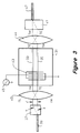
- Figure 3 shows an embodiment of the polarization independent AOTF system of this invention.
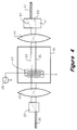
- Figure 4 shows the path traveled by the out-of-band components of light in the embodiment of Figure 3.
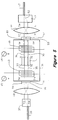
- Figure 5 shows another embodiment of this invention comprising two stages of filtering on a single AOTF substrate.
- Figure 6 shows another embodiment of this invention in which two stages of filtering are obtained by passing an incoming optical signal through the same AOTF twice.
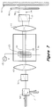
- Figure 7 shows the path traveled by the out-of-band components of light in the embodiment of Figure 6.
- Figure 8 shows another embodiment of this invention in which two stages of filtering are obtained by passing an incoming optical signal through the same AOTF twice.
- the invention is embodied in an AOTF system.
- Previous AOTF system dependency on the polarization of the incoming optical signal has been overcome.
- the AOTF system according to the invention provides better optical signal bandpass filtering performance than previously possible.
- filtering of an incoming optical signal is accomplished by separating the TM and TE components of the optical signal with a first walk-off crystal.
- the TM and TE components are filtered individually by passing the components down two separate waveguides that have been formed on a single substrate comprising at least one filter stage.
- the filtering converts the optical wavelengths of the TM component that are within the passband of the filter to TE and the optical wavelengths of the TE component that are within the passband of the filter to TM.
- the optical wavelengths of the optical components that are within the passband of the filter will hereafter be called in-band components.
- the TE and TM components are recombined by a second walk-off crystal.
- the filtering characteristics can be improved by passing the incoming optical signal through more than one stage of filtering.
- FIG. 3 shows an embodiment of this invention.
- An AOTF is fabricated in an elongated crystalline substrate 31 such as lithium niobate (LiNbO 3 ).
- a first optical waveguide 33 and a second optical waveguide 35 are formed in an upper surface of the substrate, for example by indiffusion of titanium.
- a beam of light is coupled into a first walk-off crystal 37 through an input optical fiber 39.
- the first walk-off crystal 37 is oriented to pass the TM component X of the received beam of light straight through the first walk-off crystal 37 without deviating the direction of the light beam from the original direction of the received beam of light.
- the first walk-off crystal 37 is oriented to redirect the TE component Y of the received beam of light at an angle with respect to the direction of the received beam of light. Therefore, the first walk-off crystal 37 provides separate outputs for the TM component and the TE component of the received beam of light.
- the separation distance Z between the TM output and the TE output is controlled by the thickness of the first walk-off crystal 37.
- a first optical lens 40 focuses the components of light to optimize the coupling of the components of light from the first walk-off crystal 37 to the first optical waveguide 33 and the second optical waveguide 35.
- the first optical lens 40 is a 1:1 reverse imaging lens.
- the TE component of light from the first walk-off crystal 37 is coupled into the second optical waveguide 35.
- the TM component of light from the first walk-off crystal 37 is coupled into the first optical waveguide 33.
- the TE and TM components of light propagate through the waveguides and are received by a second walk-off crystal 41.
- a first surface acoustic wave is induced in the waveguides 33, 35 by a first interdigitated transducer 43.
- the first transducer 43 is driven by an externally-generated electrical signal 45.
- the frequency of the first acoustic wave is determined by the frequency of the electrical signal.
- the first acoustic wave induces a diffraction grating in the waveguides 33, 35, and this in turn diffracts the beams of light passing through each waveguide 33, 35.
- the grating couples the TE and TM polarization modes of light. but only within a narrow band of optical wavelengths.
- the center frequency of the passband can be tuned by changing the frequency of the electrical signal that drives the first transducer 43.
- the second walk-off crystal 41 receives the TE and TM components of light from the first optical waveguide 33 and the second optical waveguide 35, respectively.
- a second optical lens 44 focuses the components of light to optimize the coupling of the light components from the first optical waveguide 33 and the second optical waveguide 35 to the second walk-off crystal 41.
- the second optical lens 44 is a 1:1 reverse imaging lens.
- Within the narrow passband defined by the acoustic wave the polarization of the light beams passing through the first optical waveguide 33 and the second optical waveguide 35 are converted to the orthogonal mode. Therefore, within the defined passband the TM component of light that is received from the first walk-off crystal 37 is converted to TE before being received by the second walk-off crystal 41.
- the TE component of light that is received from the first walk-off crystal 37 is converted to TM before being received by the second walk-off crystal 41.
- the TE and TM components of light within the defined passband will be recombined by the second walk-off crystal 41 to form a single output which is coupled to an output optical fiber 47.
- Figure 4 depicts the paths traveled by the TE and TM components of light that are outside the defined passband of the AOTF.
- the dashed lines 51, 53 within the second walk-offcrystal 41 depict the paths of the out-of-band light components.
- the components of light outside of the defined passband of the AOTF are not converted to the orthogonal mode when passing down the waveguides 33, 35.
- the TM and TE components of light are diffracted in the same direction in the second walk-off crystal 41 as they were in the first walk-off crystal 37. Therefore, without the orthogonal conversion of the out-of-band light components the out-of-band light component are not coupled into the output optical fiber 47. Rather, the out-of-band light component are directed along the paths depicted by the dashed lines 51, 53.
- the electrical signal 45 is turned off, then the TM and TE components of the light beam are unaffected when traveling through the waveguides 33, 35. Therefore, no light is coupled to the output optical fiber 47 through the second walk-off crystal 41.
- Figure 5 depicts another embodiment of this invention.
- the configuration of this AOTF system includes a second stage of filtering that improves the out-of-band signal suppression.
- the second stage of filtering is included by inducing a second acoustic wave in the a third waveguide 34 and a fourth waveguide 36 with a second interdigitated transducer 46.
- the second transducer 46 is driven by an externally-generated electrical signal source 48.
- the frequency of the second acoustic wave is determined by the frequency of the second electrical signal.
- the second acoustic wave induces a diffraction grating in the waveguides 34, 36, and this in turn diffracts the beams of light passing through each waveguide 34, 36.
- the grating couples the TE and TM polarization modes of light, but only within a narrow band of optical wavelengths. Thus, within this narrow band all light propagating in one polarization mode is converted to the orthogonal mode, whereas outside this band the polarization mode of the light is unaffected.
- the frequency of the beams of light are Doppler-shifted as the beams of light pass through the AOTF because the grating induced by the first acoustic wave is in motion with respect to the waveguide. If desired, the Doppler shift to the optical signals due to the first acoustic wave can be canceled by the second acoustic wave. Therefore, the filtered optical output will not be shifted in frequency.
- the embodiment of the invention shown in Figure 5 includes a first TM polarizer 51 and a second TM polarizer 53 which are attached to the two-stage AOTF with an optical epoxy.
- the TM polarizers are attached to the AOTF rather than fabricating them directly on the AOTF substrate because TM polarizers are much easier to manufacture as an individual component than to fabricate directly on an AOTF substrate.
- Component TM polarizers have better rejection ofTE polarization signals than TM polarizers built directly on an AOTF substrate.
- Attached to a lower section of the first TM polarizer 51 is a first half wave plate 59.
- the orientation of the first half wave plate 59 is set so that the incoming TE linear polarized light is converted to TM.
- Attached to an upper section of the second TM polarizer 53 is a second half wave plate 61.
- Attached to an upper section of the first TM polarizer 51 is a first piece of optically transmissive material 55 such as glass which maintains unity between the path length traveled by the two light components as determined by the first walk-off crystal 37.
- Attached to a lower section of the second TM polarizer 53 is a second piece of optically transmissive material 57 which also maintains unity between the path lengths traveled by the two light components.
- TE polarizer 63 Fabricated on the substrate 31 is a TE polarizer 63.
- TE polarizers are much easier to fabricate on an AOTF substrate than TM polarizers.
- a similar embodiment can be constructed incorporating a TM polarizer, but such an embodiment is much more difficult to construct.
- the optical components traveling down the first and second optical waveguides 33, 35 are coupled into the TE polarizer 63.
- the TE polarizer 63 passes TE optical components coupled from the first and second optical waveguides 33, 35 and substantially attenuates any other optical components.
- the outputs of the TE polarizer 63 are coupled into the third waveguide 34 and the fourth waveguide 36.
- the theory of operation of the embodiment of Figure 5 is as follows.
- the first walk-offcrystal 37 receives an optical signal of an unspecified polarization from an input optical fiber 39 and separates the optical signal into TE and TM optical components.
- the TM optical component passes straight through the crystal whereas the TE optical component is redirected.
- the first walk-off crystal 37 separates the TE and TM optical components by a distance that is controlled by the thickness of the first walk-off crystal 37.
- the thickness of the crystal is selected so that the TE and TM components are transmitted from the walk-off crystal separated by a distance equal to the distance between the first waveguide and the second waveguide.
- the TM and TE components of light pass through the first lens 40. Passing through the first lens 40 focuses the components of light to more optimally couple the components of light to the first and second waveguides 33, 35.
- the TE component of light After passing though the first lens 40, the TE component of light passes through the first half wave plate 59 which is orientated to rotate the TE component to TM. Simultaneously, the original TM component passes without a polarization conversion through the first piece of optical material 55. Both components of light then pass through the first TM polarizer 51 which greatly attenuates any residual TE components still present in either of the TM optical signal components.
- both of the TM signals After passing through the first TM polarizer, both of the TM signals are coupled into the first and second waveguides 33, 35 and pass through the first acoustic wave induced by the first transducer 43.
- the frequency components of both of the TM optical signals within the pass-band of the AOTF are converted to TE.
- the out-of-band frequency components of both of the TM optical signals remain TM.
- the two optical signals passed down the first and second waveguides 33, 35 are coupled into the TE polarizer 63.
- the TE polarizer 63 rejects the out-of-band TM frequency components of both optical signal.
- the in band TE components of both optical signal are allowed to pass.
- the two TE optical signals passing through the TE polarizer 63 are coupled into the third and fourth waveguides 34, 36 and pass through the second acoustic wave induced by the second transducer 46.
- the frequency components of both of the TE optical signals within the pass-band of the AOTF are converted to TM.
- the out-of-band frequency components of both of the TE optical signals remain TE.
- the two optical signals then pass through the second TM polarizer 53 which greatly attenuates the out-of-band TE components of both optical signals.
- the in band TM components of both optical signal are allowed to pass with minimal attenuation.
- the TM component transmitting from the third waveguide 34 is converted to TE by passing the TM optical component through the second half wave plate 61.
- the TM optical component transmitting from the fourth waveguide 36 passes through the second piece of optical material 57.
- Both optical components pass through a second optical lens 44.
- the second optical lens 44 focuses the optical components so that the optical components are more effectively coupled to the second walk-off crystal 41.
- the TM component again passes directly through the second walk-off crystal whereas the TE optical component is redirected as depicted by the dashed line 52 in Figure 5.
- the TM and TE component are recombined in the second walk-off crystal.
- the spacing between the first waveguide 33 and the second waveguide 35 determine the thickness of the second walk-offcrystal 41.
- the optical signal transmitted from the second walk-off crystal represents the original optical signal having passed through two stages of band pass filtering.
- the optical signal transmitting from the second walk-off crystal is coupled into the output optical fiber 47.
- Figure 6 shows another embodiment of this invention.
- two stages of signal filtering are realized whit only one transducer 43 on the substrate 31.
- Two stages of filtering are realized by passing the incoming beam of light through the AOTF a first time, reflecting the beam of light off of a mirror 67 and then passing the beam of light through the same AOTF a second time.
- a band pass filtered representation of the original beam of light is obtained at a circulator output 71 of an optical circulator 69 located at the input of the embodiment.
- the incoming beam of light to be filtered is coupled through the circulator 69 and into the first walk-off crystal 37.
- the first walk-off crystal 37 separates the incoming beam of light into TE and TM optical signal components which are coupled into the first and second waveguides 33, 35.
- the frequency components of the TE and TM optical signals within the passband of the filter are each converted to the orthogonal mode.
- a 45° Faraday rotator 65 and a mirror 67 are located at the output of the second walk-off crystal 41.
- the 45° Faraday rotator 65 may be replaced with a quarter wavelength plate.
- the second walk-off crystal 41 combines the TM and TE optical signal components that are within the defined filter passband.
- the second walk-off crystal 41 does not combines the TM and TE optical signal components that are not within the defined filter passband.
- the combined optical signal transmitted from the second walk-off crystal passes through the 45° Faraday rotator 65, reflects off of the mirror 67 and passes back through the 45° Faraday rotator 65 a second time.
- the TM and TE optical signal components experience a quarter wavelength phase shift upon passing through the 45° Faraday rotator 65.
- the two quarter wavelength phase shifts of the optical components converts the TM component to TE and converts the TE component to TM.
- the reflected optical signal is separated into orthogonal TE and TM optical signal components upon passing back through the second walk-off crystal 41.
- the TE and TM optical signal components are coupled back into and travel back down the first and second waveguides 33, 35.
- the frequency components of the optical signal within the pass band of the AOTF are once again converted to the orthogonal mode.
- the first walk-off crystal 37 combines the frequency components of the TE and TM optical components that are within the filter pass band.
- the frequency components that are outside of the filter pass band are not combined within the first walk-off crystal.
- the combined filtered optical components are coupled back into the circulator 69.
- a circulator output 71 provides access to the filtered optical signal comprising the combined filtered optical components.
- the configuration of this embodiment causes the optical component that initially passes down the first waveguide 33 to pass down the second waveguide 35 after being reflected off the mirror 67.
- the optical component that initially passes down the second waveguide 35 passes down the first waveguide 33 after the optical component has been reflected off of the mirror 67.
- the result is that the Doppler frequency shift to the optical component during the first pass through the AOTF is canceled during the second pass. Therefore, this configuration has the added benefit that the filtered output is not frequency shifted from the original optical signal frequency.
- the second walk-off-crystal 41 of this embodiment attenuates the out-of-band frequency components of the optical components.
- the dashed lines 76, 78 in Figure 7 depict the paths of the out-of-band optical components.
- the second walk-off-crystal directs the out-of-band frequency components so that the out-of-band frequency components do not combine and are not coupled back into the AOTF after reflecting from the mirror 67. Therefore, the second walk-off-crystal provides filtering of the original optical signal.
- Figure 8 shows another embodiment of this invention. As in the previous embodiment, two stages of signal filtering are obtained with only one transducer 43 fabricated on the substrate 31. This embodiment does not, however, require the second walk-off crystal 41 or the circulator 69.
- An incoming beam of light is once again coupled into a first walk-off crystal 37.
- the walk-off crystal 37 separates the incoming beam of light into TE and TM optical components.
- the TE and TM components of light are coupled into the first and second waveguides 33, 35.
- the TE and TM optical signal components travel down the first and second waveguides 33, 35 and the frequency components of the TE and TM optical components within the passband are converted to the orthogonal mode.
- the in-band TE optical signal component transmitting from the first waveguide passes through the second optical lens 44, the 45° Faraday rotator 65, a TE plus 45° polarizer 84, reflects off the mirror 67, and travel back through the TE plus 45° polarizer 84, the 45° Faraday rotator 65 and the second optical lens 44.
- the in-band TM optical signal component transmitting from the first waveguide passes through the second optical lens 44, the 45° Faraday rotator 65, a TM plus 45° polarizer 82, reflects off the mirror 67, and travel back through the TM plus 45° polarizer 82, the 45° Faraday rotator 65 and the second optical lens 44.
- the TM plus 45° polarizer 84 and the TE plus 45° polarizer 82 provide attenuation of out-of-band frequency components of the optical signals.
- the optical components are converted to the orthogonal mode upon passing through the 45° Faraday rotator 65 twice.
- the first waveguide 33 receives the reflected TM optical component and the second waveguide 35 receives the reflected TE optical component.
- the components of light are passed back through the first and second waveguides 33, 35 and the polarization of the light beams are converted to the orthogonal mode within the narrow passband defined by the acoustic wave.
- the components of light transmit from the first and second waveguides 33, 35 and pass back through the first lens 40.
- the first lens 40 focuses the components of light to enhance the coupling of the components of light back into the first walk-off crystal 37.
- the first walk-off crystal 37 of this embodiment has a TM output 68 and a TE output 69.
- the TM component of the twice filtered reflected beam of light passes straight through the first walk-off crystal and is coupled to the TM output 68.
- the TE component of the twice filtered reflected beam of light is directed diagonally through the first walk-off crystal and is coupled to the TE output 69.
Landscapes
- Physics & Mathematics (AREA)
- Nonlinear Science (AREA)
- General Physics & Mathematics (AREA)
- Optics & Photonics (AREA)
- Optical Modulation, Optical Deflection, Nonlinear Optics, Optical Demodulation, Optical Logic Elements (AREA)
- Optical Integrated Circuits (AREA)
Applications Claiming Priority (2)
| Application Number | Priority Date | Filing Date | Title |
|---|---|---|---|
| US594074 | 1996-01-30 | ||
| US08/594,074 US5611004A (en) | 1996-01-30 | 1996-01-30 | Microphotonic polarization independent acousto optical tunable filter and receiver |
Publications (1)
| Publication Number | Publication Date |
|---|---|
| EP0788010A1 true EP0788010A1 (en) | 1997-08-06 |
Family
ID=24377417
Family Applications (1)
| Application Number | Title | Priority Date | Filing Date |
|---|---|---|---|
| EP97300363A Withdrawn EP0788010A1 (en) | 1996-01-30 | 1997-01-21 | Polarization-independent acousto-optical tunable filter |
Country Status (3)
| Country | Link |
|---|---|
| US (1) | US5611004A (enExample) |
| EP (1) | EP0788010A1 (enExample) |
| JP (1) | JPH09211406A (enExample) |
Families Citing this family (29)
| Publication number | Priority date | Publication date | Assignee | Title |
|---|---|---|---|---|
| IT1277412B1 (it) * | 1995-08-02 | 1997-11-10 | Pirelli Cavi S P A Ora Pirelli | Dispositivo acusto-ottico in guida d'onda sintonizzabile a risposta indipendente dalla polarizzazione e metodo di trattamento acusto- |
| JP2765529B2 (ja) * | 1995-09-29 | 1998-06-18 | 日本電気株式会社 | 導波路形光デバイス |
| EP0814362A1 (en) * | 1996-06-20 | 1997-12-29 | PIRELLI CAVI S.p.A. | Polarization-independent, tunable, acousto-optical waveguide device for the wavelength selection of an optical signal |
| US5734763A (en) * | 1996-09-04 | 1998-03-31 | Hewlett-Packard Company | Compact two-by-n optical components based on bierfringent walk-off crystals |
| US6016216A (en) * | 1997-05-17 | 2000-01-18 | Aurora Photonics, Inc. | Polarization-independent acousto-optic tunable filter |
| US6064510A (en) * | 1998-02-05 | 2000-05-16 | Carnegie Mellon University | Spectro-polarimetric imager |
| US6357913B1 (en) * | 1998-02-12 | 2002-03-19 | Novera Optics, Inc. | Add/drop acousto-optic filter |
| JP3000995B2 (ja) * | 1998-03-03 | 2000-01-17 | 日本電気株式会社 | 導波路型偏光無依存光波長可変フィルタ |
| US6052497A (en) * | 1998-05-22 | 2000-04-18 | Lucent Technologies Inc. | System comprising acousto-optic tunable filter |
| US6370167B1 (en) | 1998-09-29 | 2002-04-09 | Corning O.T.I. S.P.A. | Double-passage acousto-optical device and laser |
| EP0989440A1 (en) * | 1998-09-29 | 2000-03-29 | PIRELLI CAVI E SISTEMI S.p.A. | Double-pass acousto-optical device and laser |
| BR9916589A (pt) | 1998-12-24 | 2001-09-25 | Optical Technologies Italia | Multiplexador de adição/diminuição acusto-ótico, conexão cruzada óptica seletiva de comprimento de onda, dispositivo de guia de onda acusto-ótica seletivo em comprimento de onde e método de multiplexação de canais ópticos |
| US6169626B1 (en) | 1999-06-29 | 2001-01-02 | E-Tek Dynamics | Optical signal interleaver |
| US6275322B1 (en) | 1999-06-08 | 2001-08-14 | Jds Uniphase Corporation | Michelson phase shifter interleaver/deinterleavers |
| US6493473B1 (en) * | 1999-08-03 | 2002-12-10 | Uniphase Telecommunciations Products, Inc. | Method and apparatus for providing transformation of the polarization of light |
| US6721466B2 (en) * | 1999-12-23 | 2004-04-13 | Henry F. Taylor | Guided wave electrooptic and acoustooptic tunable filter apparatus and method |
| US6301046B1 (en) | 1999-12-31 | 2001-10-09 | Jds Uniphase Corporation | Interleaver/deinterleavers causing little or no dispersion of optical signals |
| US6337770B1 (en) | 1999-12-31 | 2002-01-08 | Jds Uniphase Corporation | Single-pass folded interleaver/deinterleavers |
| US6335830B1 (en) | 1999-12-31 | 2002-01-01 | Jds Uniphase Corporation | Double-pass folded interleaver/deinterleavers |
| US6333816B1 (en) | 2000-03-03 | 2001-12-25 | Jds Uniphase Corporation | Apparatus capable of operating as interleaver/deinterleavers or filters |
| RU2176411C1 (ru) * | 2000-03-31 | 2001-11-27 | Павлов Борис Сергеевич | Оптико-акустический частотный фильтр |
| US6628850B1 (en) * | 2001-02-15 | 2003-09-30 | General Photonics Corporation | Dynamic wavelength-selective grating modulator |
| US6804057B1 (en) | 2002-02-06 | 2004-10-12 | Novera Optics, Inc. | Various methods and apparatuses for a tunable chromatic dispersion compensator |
| US7035484B2 (en) * | 2002-04-12 | 2006-04-25 | Xtellus, Inc. | Tunable optical filter |
| US6922281B2 (en) * | 2002-05-03 | 2005-07-26 | Lightwaves 2020, Inc. | Erbium-doped fiber amplifier and integrated module components |
| US6788845B1 (en) | 2002-05-31 | 2004-09-07 | Novera Optics, Inc. | Methods and apparatuses to provide a tunable chromatic dispersion compensator |
| US20040101264A1 (en) * | 2002-11-27 | 2004-05-27 | Mcalexander William Ian | Programmable integrated-optical device and a method for making and using the same |
| WO2004091387A2 (en) * | 2003-04-15 | 2004-10-28 | Optiscan Biomedical Corporation | Dual measurement analyte detection system |
| JP5182049B2 (ja) * | 2008-12-09 | 2013-04-10 | 富士通株式会社 | 偏波変換デバイス及び偏波多重変調器 |
Citations (3)
| Publication number | Priority date | Publication date | Assignee | Title |
|---|---|---|---|---|
| US3982817A (en) * | 1974-02-25 | 1976-09-28 | Westinghouse Electric Corporation | Collinear acousto-optical tunable filter and acousto-optically tunable laser |
| US4268871A (en) * | 1976-03-30 | 1981-05-19 | Canon Kabushiki Kaisha | Scanning optical system for formation of a half tone image |
| US5455877A (en) * | 1994-10-27 | 1995-10-03 | Bell Communications Research, Inc. | Multi-channel wavelength-routing switch using acousto-optic polarization converters |
Family Cites Families (7)
| Publication number | Priority date | Publication date | Assignee | Title |
|---|---|---|---|---|
| US3817598A (en) * | 1972-09-25 | 1974-06-18 | Us Navy | Laser beam deflection system |
| US4052121A (en) * | 1975-09-10 | 1977-10-04 | Itek Corporation | Noncollinear tunable acousto-optic filter |
| US4490845A (en) * | 1982-02-02 | 1984-12-25 | Westinghouse Electric Corp. | Automated acousto-optic infrared analyzer system |
| US4637689A (en) * | 1983-04-06 | 1987-01-20 | Itek Corporation | Acoustically resonant tunable acousto-optic filter |
| US5002349A (en) * | 1989-11-29 | 1991-03-26 | Bell Communications Research, Inc. | Integrated acousto-optic filters and switches |
| US5159481A (en) * | 1990-09-14 | 1992-10-27 | Bell Communications Research, Inc. | Polarization scrambler for polarization-sensitive optical devices |
| US5230005A (en) * | 1991-11-05 | 1993-07-20 | The United States Of America As Represented By The Secretary Of The Navy | Electronic tuning of a broadband laser |
-
1996
- 1996-01-30 US US08/594,074 patent/US5611004A/en not_active Expired - Fee Related
-
1997
- 1997-01-21 EP EP97300363A patent/EP0788010A1/en not_active Withdrawn
- 1997-01-30 JP JP9031128A patent/JPH09211406A/ja active Pending
Patent Citations (3)
| Publication number | Priority date | Publication date | Assignee | Title |
|---|---|---|---|---|
| US3982817A (en) * | 1974-02-25 | 1976-09-28 | Westinghouse Electric Corporation | Collinear acousto-optical tunable filter and acousto-optically tunable laser |
| US4268871A (en) * | 1976-03-30 | 1981-05-19 | Canon Kabushiki Kaisha | Scanning optical system for formation of a half tone image |
| US5455877A (en) * | 1994-10-27 | 1995-10-03 | Bell Communications Research, Inc. | Multi-channel wavelength-routing switch using acousto-optic polarization converters |
Non-Patent Citations (4)
| Title |
|---|
| CHEUNG K W: "1 X 2 POLARISATION-INDEPENDENT ACOUSTO-OPTIC FILTER TUNABLE OVER 1.30-1.56 M", ELECTRONICS LETTERS, vol. 27, no. 4, 14 February 1991 (1991-02-14), pages 314 - 315, XP000219829 * |
| FUKUTOKU M ET AL: "WAVELENGTH-DIVISION-MULTIPLEXING ADD/DROP MULTIPLEXER EMPLOYING A NOVEL POLARISATION INDEPENDENT ACOUSTO-OPTIC TUNABLE FILTER", ELECTRONICS LETTERS, vol. 29, no. 10, 13 May 1993 (1993-05-13), pages 905 - 907, XP000367666 * |
| SMITH D A ET AL: "POLARIZATION-INDEPENDENT ACOUSTICALLY TUNABLE OPTICAL FILTER", APPLIED PHYSICS LETTERS, vol. 56, no. 3, 15 January 1990 (1990-01-15), pages 209 - 211, XP000127383 * |
| SMITH D A ET AL: "TWO-STAGE INTEGRATED-OPTIC ACOUSTICALLY TUNABLE OPTICAL FILTER WITH ENHANCED SIDELOBE SUPPRESSION", ELECTRONICS LETTERS, vol. 25, no. 6, 16 March 1989 (1989-03-16), pages 398/399, XP000045601 * |
Also Published As
| Publication number | Publication date |
|---|---|
| US5611004A (en) | 1997-03-11 |
| JPH09211406A (ja) | 1997-08-15 |
Similar Documents
| Publication | Publication Date | Title |
|---|---|---|
| US5611004A (en) | Microphotonic polarization independent acousto optical tunable filter and receiver | |
| US5724373A (en) | Microphotonic acousto-optic tunable laser | |
| CA2004998C (en) | Integrated acousto-optic filters and switches | |
| US4685773A (en) | Birefringent optical multiplexer with flattened bandpass | |
| US5652809A (en) | Offset rotated transducers for acousto-optical tunable filters | |
| Smith et al. | Integrated-optic acoustically-tunable filters for WDM networks | |
| US5329397A (en) | Acousto-optic tunable filter | |
| JPH09211406A5 (enExample) | ||
| JP3119540B2 (ja) | 光タップ | |
| US7120333B2 (en) | Polarization insensitive tunable optical filters | |
| JPH07154372A (ja) | 光通信ネットワークにおける光搬送波抽出,再挿入機器 | |
| TW320689B (enExample) | ||
| PL180680B1 (pl) | Akustooptyczne urzadzenie falowodowe do wybierania dlugosci fal oraz sposób jego wytwarzania PL PL PL PL PL PL PL PL PL PL PL | |
| JP2000147247A (ja) | チューナブル光学フィルタ | |
| JP2003508795A (ja) | 反射及び波長選択光学クロスコネクトにおけるラインを備えたadm | |
| US5909304A (en) | Acousto-optic tunable filter based on isotropic acousto-optic diffraction using phased array transducers | |
| JPH0816739B2 (ja) | 波長分岐挿入素子 | |
| US6718076B2 (en) | Acousto-optic tunable filter with segmented acousto-optic interaction region | |
| Molchanov et al. | Quasi-collinear tunable acousto-optic paratellurite crystal filters for wavelength division multiplexing and optical channel selection | |
| Nakazawa et al. | Ti: LiNbO3 AOTF for 0.8 nm channel-spaced WDM | |
| US20030090672A1 (en) | Deinterleaver with high isolation and dispersion compensation and 50/200GHz interleaver and deinterleaver | |
| US20050041911A1 (en) | Optical space-switching matrix | |
| JP6848451B2 (ja) | 偏波結合装置および光変調装置 | |
| JP2975497B2 (ja) | インライン型光アイソレータ | |
| JPH01257921A (ja) | 光回路素子 |
Legal Events
| Date | Code | Title | Description |
|---|---|---|---|
| PUAI | Public reference made under article 153(3) epc to a published international application that has entered the european phase |
Free format text: ORIGINAL CODE: 0009012 |
|
| AK | Designated contracting states |
Kind code of ref document: A1 Designated state(s): DE FR GB |
|
| 17P | Request for examination filed |
Effective date: 19980203 |
|
| 17Q | First examination report despatched |
Effective date: 19981230 |
|
| STAA | Information on the status of an ep patent application or granted ep patent |
Free format text: STATUS: THE APPLICATION IS DEEMED TO BE WITHDRAWN |
|
| 18D | Application deemed to be withdrawn |
Effective date: 19990511 |