EP0787914B1 - Gleitlageranordnung mit einem buchsenförmigen Gleitlagerelement - Google Patents
Gleitlageranordnung mit einem buchsenförmigen Gleitlagerelement Download PDFInfo
- Publication number
- EP0787914B1 EP0787914B1 EP96119126A EP96119126A EP0787914B1 EP 0787914 B1 EP0787914 B1 EP 0787914B1 EP 96119126 A EP96119126 A EP 96119126A EP 96119126 A EP96119126 A EP 96119126A EP 0787914 B1 EP0787914 B1 EP 0787914B1
- Authority
- EP
- European Patent Office
- Prior art keywords
- slide bearing
- bearing element
- bearing arrangement
- arrangement according
- aperture
- Prior art date
- Legal status (The legal status is an assumption and is not a legal conclusion. Google has not performed a legal analysis and makes no representation as to the accuracy of the status listed.)
- Expired - Lifetime
Links
- 239000000463 material Substances 0.000 claims description 8
- 238000007789 sealing Methods 0.000 claims description 5
- 239000012791 sliding layer Substances 0.000 claims description 5
- 239000011888 foil Substances 0.000 claims description 2
- 238000003780 insertion Methods 0.000 claims description 2
- 230000037431 insertion Effects 0.000 claims description 2
- 229920003023 plastic Polymers 0.000 claims description 2
- 239000004033 plastic Substances 0.000 claims description 2
- 239000007787 solid Substances 0.000 claims description 2
- 229910001369 Brass Inorganic materials 0.000 claims 2
- 229910000906 Bronze Inorganic materials 0.000 claims 2
- 239000004411 aluminium Substances 0.000 claims 2
- XAGFODPZIPBFFR-UHFFFAOYSA-N aluminium Chemical compound [Al] XAGFODPZIPBFFR-UHFFFAOYSA-N 0.000 claims 2
- 229910052782 aluminium Inorganic materials 0.000 claims 2
- 239000010951 brass Substances 0.000 claims 2
- 239000010974 bronze Substances 0.000 claims 2
- KUNSUQLRTQLHQQ-UHFFFAOYSA-N copper tin Chemical compound [Cu].[Sn] KUNSUQLRTQLHQQ-UHFFFAOYSA-N 0.000 claims 2
- 229910000831 Steel Inorganic materials 0.000 claims 1
- 239000010959 steel Substances 0.000 claims 1
- 239000004744 fabric Substances 0.000 description 2
- 238000004519 manufacturing process Methods 0.000 description 2
- 239000000126 substance Substances 0.000 description 2
- 238000005299 abrasion Methods 0.000 description 1
- 239000002131 composite material Substances 0.000 description 1
- 230000003247 decreasing effect Effects 0.000 description 1
- 238000005553 drilling Methods 0.000 description 1
- 239000000314 lubricant Substances 0.000 description 1
- 238000005461 lubrication Methods 0.000 description 1
- 238000000034 method Methods 0.000 description 1
- 238000003860 storage Methods 0.000 description 1
Images
Classifications
-
- F—MECHANICAL ENGINEERING; LIGHTING; HEATING; WEAPONS; BLASTING
- F16—ENGINEERING ELEMENTS AND UNITS; GENERAL MEASURES FOR PRODUCING AND MAINTAINING EFFECTIVE FUNCTIONING OF MACHINES OR INSTALLATIONS; THERMAL INSULATION IN GENERAL
- F16C—SHAFTS; FLEXIBLE SHAFTS; ELEMENTS OR CRANKSHAFT MECHANISMS; ROTARY BODIES OTHER THAN GEARING ELEMENTS; BEARINGS
- F16C17/00—Sliding-contact bearings for exclusively rotary movement
- F16C17/10—Sliding-contact bearings for exclusively rotary movement for both radial and axial load
-
- B—PERFORMING OPERATIONS; TRANSPORTING
- B21—MECHANICAL METAL-WORKING WITHOUT ESSENTIALLY REMOVING MATERIAL; PUNCHING METAL
- B21K—MAKING FORGED OR PRESSED METAL PRODUCTS, e.g. HORSE-SHOES, RIVETS, BOLTS OR WHEELS
- B21K21/00—Making hollow articles not covered by a single preceding sub-group
- B21K21/02—Producing blanks in the shape of discs or cups as semifinished articles for making hollow articles, e.g. to be deep-drawn or extruded
-
- F—MECHANICAL ENGINEERING; LIGHTING; HEATING; WEAPONS; BLASTING
- F16—ENGINEERING ELEMENTS AND UNITS; GENERAL MEASURES FOR PRODUCING AND MAINTAINING EFFECTIVE FUNCTIONING OF MACHINES OR INSTALLATIONS; THERMAL INSULATION IN GENERAL
- F16C—SHAFTS; FLEXIBLE SHAFTS; ELEMENTS OR CRANKSHAFT MECHANISMS; ROTARY BODIES OTHER THAN GEARING ELEMENTS; BEARINGS
- F16C17/00—Sliding-contact bearings for exclusively rotary movement
- F16C17/04—Sliding-contact bearings for exclusively rotary movement for axial load only
- F16C17/08—Sliding-contact bearings for exclusively rotary movement for axial load only for supporting the end face of a shaft or other member, e.g. footstep bearings
Definitions
- the invention relates to a plain bearing arrangement from a a housing through hole used slide bearing element and a shaft, an axis, a journal mounted therein or another rotatable component.
- Plain bearing elements are used to support shafts and axles in the form of bushings or flange bushings or also in the form of Bearing cups used to form a bearing bush put together, used.
- socket-shaped Plain bearing elements have the problem of being abrasive acting substances, such as dirt, abrasion or the like, of get to the outside of the depository and get damaged there can impact. Furthermore, there is the problem that unwanted substances, such as lead, fat, oil the bearing point to the outside.
- a bush-shaped plain bearing element in a through opening a housing is arranged, the above So far, problems have been countered by the fact that an additional Sealing element used in the through opening or was pressed in to seal the bearing.
- a slide bearing arrangement is known from GB-A-2 079 872 with a cup-shaped plain bearing element, which in a Through hole inserted and through a snap ring in the through opening is held.
- the present invention has for its object a Plain bearing arrangement of the type described in the opening paragraph With regard to the disadvantages described above improve.
- the design of the floor area of the Plain bearing element for its intended function is not mandatory, provided that side facing away from the shaft is limited by the floor area, it proves to be space-saving and therefore advantageous if the floor area is substantially perpendicular to the Socket longitudinal axis runs.
- the plain bearing element can be made from a solid or Mono material exist, but it can also be composite be constructed. In the latter case, the plain bearing element a metallic support with one attached to it Include sliding layer. But it can also be one Foil material, e.g. in the form of one with plastic impregnated fabric or knitted fabric.
- the plain bearing element is facing away from the shaft Side of the through hole pressed into this, so that at Compliance with the usual guidelines for the design of the Connecting parts the resulting frictional heat to the housing and can also be discharged to the shaft.
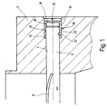
- the figure shows a section Housing wall 2 of a motor vehicle carburetor.
- a through hole 4 is formed, in which a Throttle body 6, one with the reference numeral 8 indicated throttle carries, is rotatably mounted.
- a cup-shaped cross section is formed Slide bearing element 10 is provided, which of the nozzle 6th opposite side of the bore 4 is pressed into this.
- the bore 4 has a stepped extension 12 on a stop 14 for the slide bearing element 10th forms.
- the slide bearing element 10 comprises a metallic Carrier 16 with a sliding layer 18.
- carrier 16 and sliding layer 18 formed plain bearing material can for example, that of the applicant under the Trade names "Permaglide” manufactured and distributed Act material, but without the invention thereon is limited.
- A is used to manufacture the cup-shaped plain bearing element Band for production to be produced in a manner known per se punched on a board.
- the board is then in preferably several trains with different diameters decreasing deep drawing tools deeply drawn until the illustrated cup-shaped shape with a base region 20 and a cylindrical shell portion 22 is formed.
- the inner lateral surfaces 23 form the sliding surfaces and take on the storage function while the floor area 20 of the plain bearing element 10, the sealing of the bearing point causes.
Landscapes
- Engineering & Computer Science (AREA)
- General Engineering & Computer Science (AREA)
- Mechanical Engineering (AREA)
- Sliding-Contact Bearings (AREA)
Description
Die mit der Gegenlauffläche der Welle oder Achse zusammenwirkende Gleitfläche des Gleitlagerelements ist dann gegen die von der Einsteckseite für die Welle abgewandte Seite durch den Bodenbereich abgedichtet. Hierbei ist es jedoch denkbar, daß der Bodenbereich ein Schmierloch aufweist, durch welches der Lagerstelle Schmiermittel zugeführt werden kann, sofern dies im Einzelfall gewünscht wird.
- Figur 1
- eine erfindungsgemäße Gleitlageranordnung.
Claims (8)
- Gleitlageranordnung aus einem in eine Gehäusedurchgangsöffnung (4) eingesetzten topfförmigen Gleitlagerelement (10) und einer darin gelagerten Welle (6), so daß die von der Einsteckseite für die Welle (6, 41), den Zapfen oder dergleichen abgewandte Seite des Gleitlagerelements von einem geschlossenen Bodenbereich (20, 38) begrenzt ist, dadurch gekennzeichnet, dass die Gehäusedurchgangsöffnung (4) eine abgesetzte Bohrung (12) zur Aufnahme des Gleitlagerelements (10) und zur Bildung eines Anschlags (14) für das Gleitlagerelement (10) aufweist und das Gleitlagerelement (10) von der von der Welle (6) abgewandten Seite der Gehäusedurchgangsöffnung (4) dichtend in diese eingepreßt ist.
- Gleitlageranordnung nach Anspruch 1, dadurch gekennzeichnet, daß das Gleitlagerelement (10) ein Tiefziehteil ist.
- Gleitlageranordnung nach Anspruch 1 oder 2, dadurch gekennzeichnet, daß das Gleitlagerelement (10) aus einem Massiv- oder Monowerkstoff besteht.
- Gleitlageranordnung nach einem der vorhergehenden Ansprüche, dadurch gekennzeichnet, daß das Gleitlagerelement (10) einen metallischen Träger (16) mit einer darauf aufgebrachten Gleitschicht (18, 40) umfaßt.
- Gleitlageranordnung nach Anspruch 4, dadurch gekennzeichnet, daß der metallische Träger (16) Stahl, Bronze, Messing oder Aluminium umfaßt.
- Gleitlageranordnung nach Anspruch 4 oder 5, dadurch gekennzeichnet, daß die Gleitschicht (18, 40) ein Kunststoffmaterial, Aluminium, Messing oder Bronze umfaßt.
- Gleitlageranordnung nach Anspruch 1 oder 2, dadurch gekennzeichnet, daß das Gleitlagerelement (10) einen Folienwerkstoff umfaßt.
- Gleitlageranordnung nach einem der vorhergehenden Ansprüche, dadurch gekennzeichnet, daß das Gleitlagerelement (10) derart in die Durchgangsöffnung (4) eingepreßt ist, daß seine nach außen weisende Oberfläche des Bodenbereichs (20) innerhalb der Durchgangsöffnung (4) vom Öffnungsrand abgesetzt angeordnet ist.
Applications Claiming Priority (2)
| Application Number | Priority Date | Filing Date | Title |
|---|---|---|---|
| DE19603929A DE19603929A1 (de) | 1996-02-03 | 1996-02-03 | Buchsenförmiges Gleitlagerelement |
| DE19603929 | 1996-02-03 |
Publications (2)
| Publication Number | Publication Date |
|---|---|
| EP0787914A1 EP0787914A1 (de) | 1997-08-06 |
| EP0787914B1 true EP0787914B1 (de) | 2001-09-26 |
Family
ID=7784443
Family Applications (1)
| Application Number | Title | Priority Date | Filing Date |
|---|---|---|---|
| EP96119126A Expired - Lifetime EP0787914B1 (de) | 1996-02-03 | 1996-11-29 | Gleitlageranordnung mit einem buchsenförmigen Gleitlagerelement |
Country Status (3)
| Country | Link |
|---|---|
| US (1) | US5758977A (de) |
| EP (1) | EP0787914B1 (de) |
| DE (2) | DE19603929A1 (de) |
Families Citing this family (5)
| Publication number | Priority date | Publication date | Assignee | Title |
|---|---|---|---|---|
| US6505743B1 (en) * | 2000-08-31 | 2003-01-14 | Envirotech Pumpsystems, Inc. | Unitarily-formed grit classifier tank and bearing |
| US6647896B1 (en) * | 2002-01-14 | 2003-11-18 | Ysd Industries, Inc. | Greaseless hanger assembly for a railcar door |
| DE10258232B4 (de) * | 2002-12-13 | 2012-06-14 | Volkswagen Ag | Schaltstange eines Kfz-Schaltgetriebes |
| JP2004300944A (ja) * | 2003-03-28 | 2004-10-28 | Denso Corp | 内燃機関用スロットル装置 |
| EP2400175A1 (de) * | 2010-06-24 | 2011-12-28 | KS Gleitlager GmbH | Verfahren zum Herstellen eines Gleitlagerelements |
Family Cites Families (13)
| Publication number | Priority date | Publication date | Assignee | Title |
|---|---|---|---|---|
| US596708A (en) * | 1898-01-04 | Henry houldsworth | ||
| US1817891A (en) * | 1928-01-05 | 1931-08-04 | Bound Brook Oil Less Bearing | Spring shackle |
| DE1422629A1 (de) * | 1962-07-30 | 1969-01-02 | Licentia Gmbh | Lageranordnung fuer zwischen Platinen gelagerten Achsen |
| NL6902447A (de) * | 1969-02-14 | 1970-08-18 | ||
| FR2278985A1 (fr) * | 1974-03-05 | 1976-02-13 | Pitner Alfred | Coussinet pour palier lisse |
| JPS5351172A (en) * | 1976-10-21 | 1978-05-10 | Wako Kk | Method of fabricating flanged hollow products |
| DE3027262A1 (de) * | 1980-07-18 | 1982-02-11 | Skf Kugellagerfabriken Gmbh, 8720 Schweinfurt | Im ziehverfahren hergestellte, duennwandige lagerbuechse |
| DE3103343C2 (de) * | 1981-01-31 | 1985-01-17 | Skf Kugellagerfabriken Gmbh, 8720 Schweinfurt | Verfahren zum spanlosen Herstellen einer mit einem Boden versehenen Lagerhülse |
| CH659689A5 (de) * | 1982-12-24 | 1987-02-13 | Papst Motoren Gmbh & Co Kg | Lager fuer die abstuetzung von wellen von elektromotoren. |
| JPS6124815A (ja) * | 1984-07-13 | 1986-02-03 | Daido Metal Kogyo Kk | 軸受ブシユ |
| GB2193268B (en) * | 1984-07-26 | 1989-05-24 | Daido Metal Co | A flanged bush and a method of and apparatus for producing a flanged bush |
| JPH0643851B2 (ja) * | 1986-03-13 | 1994-06-08 | 大同メタル工業株式会社 | 軸受ユニット |
| DE4243781C2 (de) * | 1992-12-23 | 1995-07-13 | Glyco Metall Werke | Gerollte Lagerbuchse |
-
1996
- 1996-02-03 DE DE19603929A patent/DE19603929A1/de not_active Withdrawn
- 1996-11-29 EP EP96119126A patent/EP0787914B1/de not_active Expired - Lifetime
- 1996-11-29 DE DE59607773T patent/DE59607773D1/de not_active Expired - Fee Related
-
1997
- 1997-01-31 US US08/792,309 patent/US5758977A/en not_active Expired - Fee Related
Also Published As
| Publication number | Publication date |
|---|---|
| EP0787914A1 (de) | 1997-08-06 |
| DE19603929A1 (de) | 1997-08-07 |
| DE59607773D1 (de) | 2001-10-31 |
| US5758977A (en) | 1998-06-02 |
Similar Documents
| Publication | Publication Date | Title |
|---|---|---|
| DE60109298T2 (de) | Gleitlager | |
| DE3906889C2 (de) | Flanschlager und Verfahren zu seiner Herstellung | |
| DE10250147A1 (de) | Kugelgelenk | |
| DE102020200947B4 (de) | Halbes drucklager für kurbelwelle eines verbrennungsmotors | |
| DE4327911C2 (de) | Anordnung eines Wälzlagers in einem Lagergehäuse einer Kraftfahrzeug-Radaufhängung | |
| DE102020200943B4 (de) | Halbes drucklager für kurbelwelle eines verbrennungsmotors | |
| DE102004026658A1 (de) | Hybridgehäuse | |
| DE102009036986B4 (de) | Ausgleichsgetriebe | |
| DE19640872C2 (de) | Nocken für gebaute Nockenwelle | |
| DE3103343C2 (de) | Verfahren zum spanlosen Herstellen einer mit einem Boden versehenen Lagerhülse | |
| DE69524188T2 (de) | Verfahren zur Herstellung des Laufrings eines Lagers | |
| EP1606524A1 (de) | Lagerschale, lager und herstellungsverfahren von lagerschalen | |
| DE102021002183B4 (de) | Kugelgelenk und Verfahren für seine Herstellung | |
| EP1893878A2 (de) | Lagerschalenanordnung, lager und halbkreisförmige lagerschalenhälfte | |
| DE19603929A1 (de) | Buchsenförmiges Gleitlagerelement | |
| DE10251784B4 (de) | Schnapp-Kugelzapfen | |
| DE2418674A1 (de) | Drehgriffgarnitur fuer tueren und fenster und verfahren zu ihrer herstellung | |
| DE102006034736A1 (de) | Lagerschale und Lager für Pleuel | |
| EP2029905A2 (de) | Gerollte gleitlagerbuchse | |
| DE211589C (de) | ||
| DE102018120152B4 (de) | Verfahren zur Herstellung einer Nockenwelle | |
| DE102004038952B4 (de) | Lagerträger und Lageranordnung mit dem Lagerträger | |
| DE102020114322A1 (de) | Planetenträger mit integrierten Anlaufflächen | |
| DE102022117175B4 (de) | Axialpendelrollenlager mit einem Käfig und Verfahren zur Fertigung eines Käfigs für ein Axialpendelrollenlager | |
| DE102018009096A1 (de) | Sperrluftdichtung für einen Kraftwagen |
Legal Events
| Date | Code | Title | Description |
|---|---|---|---|
| PUAI | Public reference made under article 153(3) epc to a published international application that has entered the european phase |
Free format text: ORIGINAL CODE: 0009012 |
|
| AK | Designated contracting states |
Kind code of ref document: A1 Designated state(s): DE FR GB |
|
| 17P | Request for examination filed |
Effective date: 19980204 |
|
| RAP1 | Party data changed (applicant data changed or rights of an application transferred) |
Owner name: KS GLEITLAGER GMBH |
|
| 17Q | First examination report despatched |
Effective date: 19990719 |
|
| RTI1 | Title (correction) |
Free format text: BEARING ARRANGEMENT WITH A BUSH-SHAPED SLIDING ELEMENT |
|
| GRAG | Despatch of communication of intention to grant |
Free format text: ORIGINAL CODE: EPIDOS AGRA |
|
| RTI1 | Title (correction) |
Free format text: BEARING ARRANGEMENT WITH A BUSH-SHAPED SLIDING ELEMENT |
|
| GRAG | Despatch of communication of intention to grant |
Free format text: ORIGINAL CODE: EPIDOS AGRA |
|
| GRAH | Despatch of communication of intention to grant a patent |
Free format text: ORIGINAL CODE: EPIDOS IGRA |
|
| GRAH | Despatch of communication of intention to grant a patent |
Free format text: ORIGINAL CODE: EPIDOS IGRA |
|
| GRAA | (expected) grant |
Free format text: ORIGINAL CODE: 0009210 |
|
| AK | Designated contracting states |
Kind code of ref document: B1 Designated state(s): DE FR GB |
|
| GBT | Gb: translation of ep patent filed (gb section 77(6)(a)/1977) |
Effective date: 20010927 |
|
| REF | Corresponds to: |
Ref document number: 59607773 Country of ref document: DE Date of ref document: 20011031 |
|
| REG | Reference to a national code |
Ref country code: GB Ref legal event code: IF02 |
|
| ET | Fr: translation filed | ||
| PLBE | No opposition filed within time limit |
Free format text: ORIGINAL CODE: 0009261 |
|
| STAA | Information on the status of an ep patent application or granted ep patent |
Free format text: STATUS: NO OPPOSITION FILED WITHIN TIME LIMIT |
|
| 26N | No opposition filed | ||
| PGFP | Annual fee paid to national office [announced via postgrant information from national office to epo] |
Ref country code: GB Payment date: 20060905 Year of fee payment: 11 |
|
| PGFP | Annual fee paid to national office [announced via postgrant information from national office to epo] |
Ref country code: FR Payment date: 20061117 Year of fee payment: 11 |
|
| PGFP | Annual fee paid to national office [announced via postgrant information from national office to epo] |
Ref country code: DE Payment date: 20061208 Year of fee payment: 11 |
|
| GBPC | Gb: european patent ceased through non-payment of renewal fee |
Effective date: 20071129 |
|
| PG25 | Lapsed in a contracting state [announced via postgrant information from national office to epo] |
Ref country code: DE Free format text: LAPSE BECAUSE OF NON-PAYMENT OF DUE FEES Effective date: 20080603 |
|
| REG | Reference to a national code |
Ref country code: FR Ref legal event code: ST Effective date: 20080930 |
|
| PG25 | Lapsed in a contracting state [announced via postgrant information from national office to epo] |
Ref country code: GB Free format text: LAPSE BECAUSE OF NON-PAYMENT OF DUE FEES Effective date: 20071129 |
|
| PG25 | Lapsed in a contracting state [announced via postgrant information from national office to epo] |
Ref country code: FR Free format text: LAPSE BECAUSE OF NON-PAYMENT OF DUE FEES Effective date: 20071130 |