EP0787904B1 - Counter-balance valve - Google Patents
Counter-balance valve Download PDFInfo
- Publication number
- EP0787904B1 EP0787904B1 EP95934832A EP95934832A EP0787904B1 EP 0787904 B1 EP0787904 B1 EP 0787904B1 EP 95934832 A EP95934832 A EP 95934832A EP 95934832 A EP95934832 A EP 95934832A EP 0787904 B1 EP0787904 B1 EP 0787904B1
- Authority
- EP
- European Patent Office
- Prior art keywords
- port
- spool
- pump
- communicated
- bores
- Prior art date
- Legal status (The legal status is an assumption and is not a legal conclusion. Google has not performed a legal analysis and makes no representation as to the accuracy of the status listed.)
- Expired - Lifetime
Links
- 230000007935 neutral effect Effects 0.000 claims description 37
- 238000004891 communication Methods 0.000 claims description 15
- 230000002093 peripheral effect Effects 0.000 claims description 14
- 239000003921 oil Substances 0.000 description 39
- 230000035939 shock Effects 0.000 description 9
- 238000004519 manufacturing process Methods 0.000 description 4
- 230000000694 effects Effects 0.000 description 2
- 238000007792 addition Methods 0.000 description 1
- 230000002146 bilateral effect Effects 0.000 description 1
- 238000010276 construction Methods 0.000 description 1
- 238000013016 damping Methods 0.000 description 1
- 230000003111 delayed effect Effects 0.000 description 1
- 238000012217 deletion Methods 0.000 description 1
- 230000037430 deletion Effects 0.000 description 1
- 238000010586 diagram Methods 0.000 description 1
- 239000010720 hydraulic oil Substances 0.000 description 1
- 238000005086 pumping Methods 0.000 description 1
Images


Classifications
-
- F—MECHANICAL ENGINEERING; LIGHTING; HEATING; WEAPONS; BLASTING
- F15—FLUID-PRESSURE ACTUATORS; HYDRAULICS OR PNEUMATICS IN GENERAL
- F15B—SYSTEMS ACTING BY MEANS OF FLUIDS IN GENERAL; FLUID-PRESSURE ACTUATORS, e.g. SERVOMOTORS; DETAILS OF FLUID-PRESSURE SYSTEMS, NOT OTHERWISE PROVIDED FOR
- F15B11/00—Servomotor systems without provision for follow-up action; Circuits therefor
-
- E—FIXED CONSTRUCTIONS
- E02—HYDRAULIC ENGINEERING; FOUNDATIONS; SOIL SHIFTING
- E02F—DREDGING; SOIL-SHIFTING
- E02F9/00—Component parts of dredgers or soil-shifting machines, not restricted to one of the kinds covered by groups E02F3/00 - E02F7/00
- E02F9/20—Drives; Control devices
- E02F9/22—Hydraulic or pneumatic drives
- E02F9/2264—Arrangements or adaptations of elements for hydraulic drives
- E02F9/2267—Valves or distributors
-
- E—FIXED CONSTRUCTIONS
- E02—HYDRAULIC ENGINEERING; FOUNDATIONS; SOIL SHIFTING
- E02F—DREDGING; SOIL-SHIFTING
- E02F9/00—Component parts of dredgers or soil-shifting machines, not restricted to one of the kinds covered by groups E02F3/00 - E02F7/00
- E02F9/20—Drives; Control devices
- E02F9/22—Hydraulic or pneumatic drives
- E02F9/2264—Arrangements or adaptations of elements for hydraulic drives
- E02F9/2271—Actuators and supports therefor and protection therefor
-
- F—MECHANICAL ENGINEERING; LIGHTING; HEATING; WEAPONS; BLASTING
- F15—FLUID-PRESSURE ACTUATORS; HYDRAULICS OR PNEUMATICS IN GENERAL
- F15B—SYSTEMS ACTING BY MEANS OF FLUIDS IN GENERAL; FLUID-PRESSURE ACTUATORS, e.g. SERVOMOTORS; DETAILS OF FLUID-PRESSURE SYSTEMS, NOT OTHERWISE PROVIDED FOR
- F15B11/00—Servomotor systems without provision for follow-up action; Circuits therefor
- F15B11/02—Systems essentially incorporating special features for controlling the speed or actuating force of an output member
- F15B11/04—Systems essentially incorporating special features for controlling the speed or actuating force of an output member for controlling the speed
- F15B11/044—Systems essentially incorporating special features for controlling the speed or actuating force of an output member for controlling the speed by means in the return line, i.e. "meter out"
-
- F—MECHANICAL ENGINEERING; LIGHTING; HEATING; WEAPONS; BLASTING
- F15—FLUID-PRESSURE ACTUATORS; HYDRAULICS OR PNEUMATICS IN GENERAL
- F15B—SYSTEMS ACTING BY MEANS OF FLUIDS IN GENERAL; FLUID-PRESSURE ACTUATORS, e.g. SERVOMOTORS; DETAILS OF FLUID-PRESSURE SYSTEMS, NOT OTHERWISE PROVIDED FOR
- F15B11/00—Servomotor systems without provision for follow-up action; Circuits therefor
- F15B11/02—Systems essentially incorporating special features for controlling the speed or actuating force of an output member
- F15B11/04—Systems essentially incorporating special features for controlling the speed or actuating force of an output member for controlling the speed
- F15B11/044—Systems essentially incorporating special features for controlling the speed or actuating force of an output member for controlling the speed by means in the return line, i.e. "meter out"
- F15B11/0445—Systems essentially incorporating special features for controlling the speed or actuating force of an output member for controlling the speed by means in the return line, i.e. "meter out" with counterbalance valves, e.g. to prevent overrunning or for braking
-
- F—MECHANICAL ENGINEERING; LIGHTING; HEATING; WEAPONS; BLASTING
- F15—FLUID-PRESSURE ACTUATORS; HYDRAULICS OR PNEUMATICS IN GENERAL
- F15B—SYSTEMS ACTING BY MEANS OF FLUIDS IN GENERAL; FLUID-PRESSURE ACTUATORS, e.g. SERVOMOTORS; DETAILS OF FLUID-PRESSURE SYSTEMS, NOT OTHERWISE PROVIDED FOR
- F15B13/00—Details of servomotor systems ; Valves for servomotor systems
- F15B13/02—Fluid distribution or supply devices characterised by their adaptation to the control of servomotors
- F15B13/021—Valves for interconnecting the fluid chambers of an actuator
-
- F—MECHANICAL ENGINEERING; LIGHTING; HEATING; WEAPONS; BLASTING
- F15—FLUID-PRESSURE ACTUATORS; HYDRAULICS OR PNEUMATICS IN GENERAL
- F15B—SYSTEMS ACTING BY MEANS OF FLUIDS IN GENERAL; FLUID-PRESSURE ACTUATORS, e.g. SERVOMOTORS; DETAILS OF FLUID-PRESSURE SYSTEMS, NOT OTHERWISE PROVIDED FOR
- F15B13/00—Details of servomotor systems ; Valves for servomotor systems
- F15B13/02—Fluid distribution or supply devices characterised by their adaptation to the control of servomotors
- F15B13/04—Fluid distribution or supply devices characterised by their adaptation to the control of servomotors for use with a single servomotor
- F15B13/0401—Valve members; Fluid interconnections therefor
- F15B13/0402—Valve members; Fluid interconnections therefor for linearly sliding valves, e.g. spool valves
-
- F—MECHANICAL ENGINEERING; LIGHTING; HEATING; WEAPONS; BLASTING
- F15—FLUID-PRESSURE ACTUATORS; HYDRAULICS OR PNEUMATICS IN GENERAL
- F15B—SYSTEMS ACTING BY MEANS OF FLUIDS IN GENERAL; FLUID-PRESSURE ACTUATORS, e.g. SERVOMOTORS; DETAILS OF FLUID-PRESSURE SYSTEMS, NOT OTHERWISE PROVIDED FOR
- F15B2211/00—Circuits for servomotor systems
- F15B2211/30—Directional control
- F15B2211/305—Directional control characterised by the type of valves
- F15B2211/30505—Non-return valves, i.e. check valves
-
- F—MECHANICAL ENGINEERING; LIGHTING; HEATING; WEAPONS; BLASTING
- F15—FLUID-PRESSURE ACTUATORS; HYDRAULICS OR PNEUMATICS IN GENERAL
- F15B—SYSTEMS ACTING BY MEANS OF FLUIDS IN GENERAL; FLUID-PRESSURE ACTUATORS, e.g. SERVOMOTORS; DETAILS OF FLUID-PRESSURE SYSTEMS, NOT OTHERWISE PROVIDED FOR
- F15B2211/00—Circuits for servomotor systems
- F15B2211/30—Directional control
- F15B2211/305—Directional control characterised by the type of valves
- F15B2211/30525—Directional control valves, e.g. 4/3-directional control valve
-
- F—MECHANICAL ENGINEERING; LIGHTING; HEATING; WEAPONS; BLASTING
- F15—FLUID-PRESSURE ACTUATORS; HYDRAULICS OR PNEUMATICS IN GENERAL
- F15B—SYSTEMS ACTING BY MEANS OF FLUIDS IN GENERAL; FLUID-PRESSURE ACTUATORS, e.g. SERVOMOTORS; DETAILS OF FLUID-PRESSURE SYSTEMS, NOT OTHERWISE PROVIDED FOR
- F15B2211/00—Circuits for servomotor systems
- F15B2211/50—Pressure control
- F15B2211/505—Pressure control characterised by the type of pressure control means
- F15B2211/50563—Pressure control characterised by the type of pressure control means the pressure control means controlling a differential pressure
- F15B2211/50581—Pressure control characterised by the type of pressure control means the pressure control means controlling a differential pressure using counterbalance valves
-
- F—MECHANICAL ENGINEERING; LIGHTING; HEATING; WEAPONS; BLASTING
- F15—FLUID-PRESSURE ACTUATORS; HYDRAULICS OR PNEUMATICS IN GENERAL
- F15B—SYSTEMS ACTING BY MEANS OF FLUIDS IN GENERAL; FLUID-PRESSURE ACTUATORS, e.g. SERVOMOTORS; DETAILS OF FLUID-PRESSURE SYSTEMS, NOT OTHERWISE PROVIDED FOR
- F15B2211/00—Circuits for servomotor systems
- F15B2211/80—Other types of control related to particular problems or conditions
- F15B2211/85—Control during special operating conditions
- F15B2211/853—Control during special operating conditions during stopping
-
- Y—GENERAL TAGGING OF NEW TECHNOLOGICAL DEVELOPMENTS; GENERAL TAGGING OF CROSS-SECTIONAL TECHNOLOGIES SPANNING OVER SEVERAL SECTIONS OF THE IPC; TECHNICAL SUBJECTS COVERED BY FORMER USPC CROSS-REFERENCE ART COLLECTIONS [XRACs] AND DIGESTS
- Y10—TECHNICAL SUBJECTS COVERED BY FORMER USPC
- Y10T—TECHNICAL SUBJECTS COVERED BY FORMER US CLASSIFICATION
- Y10T137/00—Fluid handling
- Y10T137/2496—Self-proportioning or correlating systems
- Y10T137/2544—Supply and exhaust type
- Y10T137/2554—Reversing or 4-way valve systems
-
- Y—GENERAL TAGGING OF NEW TECHNOLOGICAL DEVELOPMENTS; GENERAL TAGGING OF CROSS-SECTIONAL TECHNOLOGIES SPANNING OVER SEVERAL SECTIONS OF THE IPC; TECHNICAL SUBJECTS COVERED BY FORMER USPC CROSS-REFERENCE ART COLLECTIONS [XRACs] AND DIGESTS
- Y10—TECHNICAL SUBJECTS COVERED BY FORMER USPC
- Y10T—TECHNICAL SUBJECTS COVERED BY FORMER US CLASSIFICATION
- Y10T137/00—Fluid handling
- Y10T137/2496—Self-proportioning or correlating systems
- Y10T137/2559—Self-controlled branched flow systems
- Y10T137/2562—Dividing and recombining
Definitions
- the present invention relates to a counter balance valve provided for a hydraulic circuit arrangement for driving a hydraulic motor used for a travelling apparatus of a construction machine.
- a drain passage la of a hydraulic pump 1 is connected to first and second main circuits 3 and 4 through a operation valve 2, the first and second main circuits 3 and 4 are in turn connected respectively to first and second ports 6 1 and 6 2 of a hydraulic motor 5, and a supply of a pressure oil to the first and second main circuits 3 and 4 is controlled by means of the operation valve 2. Furthermore, a counter balance valve 7 is disposed between the first and second main circuits 3 and 4.
- the operation valve 2 takes its neutral position N
- the first and second main circuits 3 and 4 are communicated with each other and the pressure oil flows out therefrom towards a tank 9, and accordingly, the counter balance valve 7 takes its neutral position N and check valves 8, 8 of the first and second main circuits 3 and 4 are closed to thereby block the hydraulic motor 5 side of the hydraulic circuit arrangement to prevent the hydraulic motor 5 from being reversely rotated by an external force.
- the operation valve 2 when the operation valve 2 is shifted to a first position a or second position b , the pressure oil is supplied to the first or second main circuit 3 or 4, and the check valves 8 thereof is opened to thereby drive the hydraulic motor 5, and at the same time, the counter balance valve 7 is switched to a first position A or second position B by the pressure oil from the first main circuit 3 or second main circuit 4, and the hydraulic oil in the second main circuit 4 or first main circuit 3 is returned to the tank 9 through the counter balance valve 7 and the operation valve 2.
- the counter balance valve 7 provided for such hydraulic circuit arrangement for driving the hydraulic motor is switched in its position to the first position A or second position B by the pressure oil from the first main circuit 3 or second main circuit 4, and when all the pressure oil flows out from these main circuits 3 and 4, the counter balance valve 7 returns to its neutral position N.
- the reduction of such shock imparted at the time of stopping the operation of the hydraulic motor 5 will be performed by delaying the shifting speed of the counter balance valve from the first or second position A or B to the neutral position N and throttling the flow of the pressure oil by the counter balance valve 7 so as to gradually flow out the pressure oil to the tank 9.
- throttles 11, 11 are arranged in circuits 10, 10 connecting the counter balance valve 7 to the first and second main circuits 3 and 4 and the degree of throttling of these throttles 11, 11 is made small to thereby delay the returning speed of the counter balance valve 7 to the neutral position N from the first or second position.
- a valve body 20 is formed with a valve bore 21 to which pump-side first and second ports 22 and 23 and motor-side first and second ports 24 and 25 are formed
- a spool 26 is fitted into the valve bore 21 so as to be slidable in the longitudinal direction thereof to thereby establish the communication between the pump-side first and second ports 22 and 23 and the motor-side first and second ports 24 and 25 or to block the communication therebetween
- left and right pressure receiving chambers 28 and 29 are formed to positions between the left and right ends of the spool 26 and plugs 40 screwed to the end portions of the valve bore 21, respectively.
- the spool 26 is maintained to its neutral position, by left and right springs 27, 27 mentioned hereinlater, at which the respective ports are closed, the spool 26 is shifted to a first travelling position by the pressure oil in the left pressure receiving chamber 28 at which the pump-side second port 23 is communicated with the motor-side second port 25, and the spool 26 is shifted to a second travelling position by the pressure oil in the right pressure receiving chamber 29 at which the pump-side first port 22 is communicated with the motor-side first port 24.
- the spool 26 is formed with left and right small diameter portions 34 and 35 at its central portion and with axial bores 30 at its left and right end portions, the axial bores 30 being communicated with the left and right small diameter portions 34 and 35 through small diameter bores 33, respectively.
- pistons 31 formed with flanged portions 39 to outer peripheral portions thereof are inserted into the axial bores 30, respectively, and the springs 27 are disposed between the flanged portions 39 and the plugs 40 to keep the spool 26 to its neutral position N by the urging forces of the springs 27 through the flanged portions 39.
- pistons 31 are respectively formed with axial oil bores 36, second small diameter bores 37 communicating the oil bores 36 with the left and right pressure receiving chambers 28 and 29, and diameter directional bores 38 for opening the oil bores 36 to the outer peripheral surfaces of the pistons 31.
- the bores 38 are closed by the inner peripheral surfaces of the axial bores 30, when the spool 26 is shifted leftward or rightward from the neutral position to an intermediate position by a predetermined distance l 2 , the bores 38 are still closed by the inner peripheral surfaces of the axial bores 30, and when the spool 26 takes a position further shifted leftward or rightward by a predetermined distance l 1 , the bores 38 are communicated with the left and right pressure receiving chambers 28 and 29 and the pump-side first or second port 22 or 23 is communicated with the motor-side first or second port 24 or 25.
- the pressure oil in the left pressure receiving chamber 28 flows to the oil bore 36 through the second small diameter bore 37 and the bore 38, flows to the pump-side first port 22 through the first small diameter bore 33, and then flows out into the tank 9 through the first main circuit 3. Accordingly, since the pressure oil flow from the left pressure receiving chamber 28 is throttled only by the first small diameter bore 33, the pressure oil in the left pressure receiving chamber 28 smoothly flows into the tank 9, and as a result, since the spool 26 can be slid at high speed, the occurrence of any cavitation can be prevented and the speed reduction can be done with an improved follow-up performance.
- the bore 38 is closed by the inner peripheral surface of the axial bore 30, the left pressure receiving chamber 28 is communicated with the pump-side first port 22 through the second diameter bore 37 and the first small diameter bore 33, the pressure oil flow is throttled by two small diameter bores 37 and 33 to attain substantially the same function as that attained by making a throttle diameter smaller than before, the pressure oil in the left pressure receiving chamber 28 hence flows out gradually towards the tank 9 and the spool 26 is moved leftward by the distance l 2 to take the neutral position shown in Fig. 2.
- the spool 26 of the counter balance valve 7 when the spool 26 of the counter balance valve 7 is slid from the travelling position to the neutral position, the spool 26 is slid with a high speed at a first half sliding time from the travelling position to the intermediate position and slid with a low speed at a latter half sliding time from the intermediate position to the neutral position, so that the occurrence of the cavitation at the first half sliding time at which the counter balance valve 7 is slid with a high speed can be prevented and the operation of the hydraulic motor can be reduced and stopped with no occurrence of a large shock at the latter half sliding time at which the counter balance valve is slid with a low speed.
- the hydraulic motor can be reduced in speed and then stopped with reduced shock as well as preventing the cavitation from occurring, and the hydraulic motor can be stopped in a short time by shifting the spool 26 to the neutral position in a short time.
- the piston 31 is provided with the flanged piston 39, the oil bore 36, the second small diameter bore 37 and the bore 38, the manufacturing of the piston 39 involves troublesome working with high cost, and accordingly, the counter balance valve itself becomes expensive.
- the present invention was conceived, in view of the above problems, for providing a counter balance valve composed of reduced constructional parts with reduced manufacturing cost and capable of being easily assembled.
- a counter balance valve which is characterized in that a valve body is provided with a valve bore having pump-side first and second ports, motor-side first and second ports and an auxiliary port, a spool fitted in the valve bore to be slidable in a longitudinal direction thereof so as to establish communication between the respective ports and to block the communication therebetween, left and right springs maintaining the spool to a neutral position thereof at which the respective ports are closed, a left pressure receiving chamber acting to shift the spool by a pressure oil supplied therein to a first travelling position at which the pump-side first port and the auxiliary port are communicated with each other and the pump-side second port and the motor-side second port are also communicated with each other, and a right pressure receiving chamber acting to shift the spool by a pressure oil supplied therein to a second travelling position at which the pump-side second port and the auxiliary port are communicated with each other and the pump-side first port and the motor-side first port
- the pressure oil in the left and right pressure receiving chambers flow out smoothly through the small and large diameter bores, and when the spool is further moved to the neutral position, the pressure oil flows out only through the small diameter bore with reduced flow rate, so that the moving speed of the spool is made faster in the first half movement but is delayed in the latter half movement.
- the spool can be returned to the neutral position in a short time while preventing the cavitation from occurring, and moreover, a portion between the motor-side second and first ports and the pump-side second and first ports can be gradually closed, thereby reducing and then stopping the operation of the hydraulic motor without giving a shock.
- the counter balance valve is composed of the valve body and the spool, components constituting the valve can be eliminated.
- the auxiliary port is formed to an intermediate portion between the pump-side first and second ports
- the spool is formed with a left small diameter portion so as to establish communication between the pump-side first port and the motor-side first port and between the pump-side first port and the auxiliary port and to block the communication and a right small diameter portion so as to establish communication between the pump-side second port and the motor-side second port and between the pump-side second port and the auxiliary port and to block the communication
- the first and second small diameter bores are opened to the left and right small diameter portions, respectively
- the first and second large diameter bores are opened to the outer peripheral surface to the spool at portions near the auxiliary port other than the small diameter bores, and when the spool is positioned to the neutral position, the first and second large diameter bores are closed by an inner peripheral surface of the valve bore and when the spool is shifted leftward or rightward by more than a predetermined distance from the neutral position thereof, the first and second large diameter bores are closed by an inner peripheral surface of the valve bore
- the auxiliary port is communicated with a hydraulic circuit acting for releasing a brake for braking the hydraulic motor.
- a valve bore 51 is formed to a valve body 50, and pump-side first and second ports 52 and 53, motor-side first and second ports 54 and 55 and an auxiliary port 65 are formed to the valve bore 51 so that the respective ports are communicated with or block from each other by means of a spool 56 inserted into the valve bore 51 to be slidable.
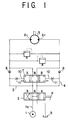
- the spool 56 is kept to its neutral position N by means of a pair of springs 57, 57, and is slidable towards a first position A and a second position B shown in Fig. 1 by pressures in left and right pressure receiving chambers 58 and 59 formed between left and right end portions of the spool 56 and left and right covers 66 closing both ends of the valve bore 51.
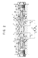
- the pump-side second port 53 and the motor-side second port 55 are communicated with each other through a right small diameter portion 63 mentioned hereinlater, and the pump-side first port 52 and the auxiliary port 65 are communicated with each other through a left small diameter portion 62 and a cutout 67 formed continuously thereto, mentioned hereinlater.
- the pump-side first port 52 and the motor-side first port 54 are communicated with each other through the left small diameter portion 62 mentioned hereinlater, and the pump-side second port 53 and the auxiliary port 65 are communicated with each other through the right small diameter portion 63 and a cutout 67 formed continuously thereto, mentioned hereinlater.
- the auxiliary port 65 is communicated with a hydraulic circuit acting to release a brake for braking the hydraulic motor 5.
- the left and right small diameter portions 62 and 63 are formed to the central portion of the spool 56 which is formed with axial bores 60 formed to the left and right portions thereof.
- the axial bores 60 are communicated respectively with the small diameter portions 62 and 63 through diameter directional bores 61 having small diameters and are opened to the outer peripheral surface of the spool 56 through large diameter bores 64.
- the both axial bores 60 are also communicated with the left and right pressure receiving chambers 58 and 59, respectively.
- the pump-side first and second ports 52 and 53 are connected, as shown in Fig. 1, to the first and second main circuits 3 and 4, respectively, and the motor-side first and second ports 54 and 55 are connected to the first and second ports 6 1 and 6 2 of the hydraulic motor 5, respectively.
- the counter balance valve of this embodiment will operates as follows.
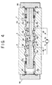
- the drain pressure oil from the hydraulic pump 1 is supplied to the first main circuit 3, and accordingly, the pressure oil in the first main circuit 3 flows in the left pressure receiving chamber 58 through the pump-side first port 52, the small diameter bore 61 and the axial bore 60 to thereby push the spool 56 rightward by a distance L 3 to a travelling position shown in Fig. 4.
- the pump-side second port 53 and the motor-side second port 55 are communicated together through the right small diameter portion 63, and the left large diameter bore 64 is communicated with the auxiliary port 65 formed to the valve bore 51.
- the pressure oil is supplied to the first port 6 1 of the hydraulic motor 5 and the pressure oil flowing out through the second port 6 2 flows towards the tank 9 through the motor-side second port 55, the pump-side second port 53 and the second main circuit 4.
- the pressure oil in the left pressure receiving chamber 58 flows to the pump-side first port 52 and then flows out into the tank 9 through the first main circuit 3 and to the auxiliary port 65 through the axial bore 60 and the large diameter bore 64. At this time, the communication between the pump-side first port 52 and the auxiliary port 65 is established.
- the throttle opening area for throttling the flow-out passage of the pressure oil in the left pressure receiving chamber 58 is a sum of the opening area of the first small diameter bore 61 and that of the large diameter bore 64, thus being large, so that the pressure oil in the left pressure receiving chamber 58 flows out therefrom smoothly, and moreover, since the spool 56 is slid at a high speed, the occurrence of the cavitation can be substantially prevented and the hydraulic motor can be reduced in speed in an improved follow-up performance.
- the spool 56 takes the intermediate position shown in Fig. 5 by being shifted leftward by a distance L 4 , the large diameter bore 64 is closed by the inner peripheral surface of the valve bore 51 and the pressure oil in the left pressure receiving chamber 58 flows out to the pump-side first port 52 through the axial bore 60 and the small diameter bore 61.
- the opening area of the pressure oil flow-out passage equals to the opening area of the small diameter bore 61, thus being small, so that the pressure oil in the left pressure receiving chamber 58 gradually flows out towards the tank 9 and the spool 56 moves leftwardly to the neutral position shown in Fig. 3 by a distance L 5 .
- the spool 56 of the counter balance valve 7 is slid with high speed in the first half movement from its travelling position to its intermediate position and with a low speed in the latter half movement from its intermediate position to the neutral position, so that the occurrence of the cavitation can be prevented in the first half movement at which the counter balance valve 7 is slid with a high speed and the hydraulic motor can be reduced in speed and stopped in the latter half movement with reduced shock.
- the hydraulic motor 5 can be stopped in a short time by shifting the spool 56 to the neutral position in a short time as well as the hydraulic motor 5 can be reduced and stopped with reduced shock while preventing the cavitation from occurring.
- the counter balance valve according to the present invention is composed of only the valve body and the spool, so that the constructional parts can be eliminated, the manufacturing cost is reduced, and the assembling working is made easy.
Landscapes
- Engineering & Computer Science (AREA)
- General Engineering & Computer Science (AREA)
- Physics & Mathematics (AREA)
- Fluid Mechanics (AREA)
- Mechanical Engineering (AREA)
- Mining & Mineral Resources (AREA)
- Civil Engineering (AREA)
- Structural Engineering (AREA)
- Chemical & Material Sciences (AREA)
- Analytical Chemistry (AREA)
- Fluid-Pressure Circuits (AREA)
- Safety Valves (AREA)
Description
Claims (3)
- A counter balance valve characterized in thata valve body (50) is provided with a valve bore (51) having pump-side first (52) and second (53) ports, motor-side first (54) and second (55) ports and an auxiliary port (65), a spool (56) fitted in the valve bore to be slidable in a longitudinal direction thereof so as to establish communication between said respective ports and to block the communication therebetween, left and right springs (57) maintaining the spool to a neutral position thereof at which said respective ports are closed, a left pressure receiving chamber (58) acting to shift said spool by a pressure oil supplied therein to a first travelling position at which said pump-side first port (52) and said auxiliary port (65) are communicated with each other and said pump-side second port (53) and said motor-side second port (55) are also communicated with each other, and a right pressure receiving chamber (59) acting to shift said spool by a pressure oil supplied therein to a second travelling position at which said pump-side second port (53) and said auxiliary port (65) are communicated with each other and said pump-side first port (52) and said motor-side first port (54) are also communicated with each other, in thatsaid spool (56) is formed with a first axial bore (60) communicated with said left pressure receiving chamber (58), a second axial bore (60) communicated with said right pressure receiving chamber (59), first and second small diameter bores (61) always communicating said first and second axial bores (60) with pump-side first and second ports (52,53), respectively, and first and second large diameter bores (64) communicating said first and second axial bores (60) with an outer peripheral surface of said spool, and in thatsaid first and second large diameter bores (64) are closed at a state that said spool is positioned to the neutral position and an intermediate position between said first and second travelling positions and said first and second large diameter bores (64) are communicated with said auxiliary port (65) at a state that said spool is positioned to said first and second travelling positions, respectively.
- A counter balance valve according to claim 1, whereinsaid auxiliary port (65) is formed to an intermediate portion between said pump-side first (52) and second (53) ports, said spool is formed with a left small diameter portion (62), so as to establish communication between said pump-side first port (52) and said motor-side first port (54) and between said pump-side first port (52) and said auxiliary port (65) and to block the communication, and a right small diameter portion (63), so as to establish communication between said pump-side second port (53) and said motor-side second port (55) and between said pump-side second port (53) and said auxiliary port (65) and to block the communication, said first and second small diameter bores (61) are opened to said left and right small diameter portions (62, 63), respectively, and said first and second large diameter bores (64) are opened to the outer peripheral surface to the spool at portions near said auxiliary port (65) other than said small diameter bores, and whereinwhen said spool (56) is positioned to the neutral position, said first and second large diameter bores (64) are closed by an inner peripheral surface of the valve bore (51) and when said spool is shifted to a leftward or rightward by more than a predetermined distance from the neutral position thereof, said first and second large diameter bores (64) are communicated with said auxiliary bore (65).
- A counter balance valve according to claim 1 or 2, wherein said auxiliary port (65) is communicated with a hydraulic circuit acting for releasing a brake for braking the hydraulic motor.
Applications Claiming Priority (4)
| Application Number | Priority Date | Filing Date | Title |
|---|---|---|---|
| JP252126/94 | 1994-10-18 | ||
| JP25212694 | 1994-10-18 | ||
| JP25212694A JP3549124B2 (en) | 1994-10-18 | 1994-10-18 | Counter balance valve |
| PCT/JP1995/002135 WO1996012110A1 (en) | 1994-10-18 | 1995-10-18 | Counter-balance valve |
Publications (3)
| Publication Number | Publication Date |
|---|---|
| EP0787904A1 EP0787904A1 (en) | 1997-08-06 |
| EP0787904A4 EP0787904A4 (en) | 1997-12-17 |
| EP0787904B1 true EP0787904B1 (en) | 2000-06-07 |
Family
ID=17232841
Family Applications (1)
| Application Number | Title | Priority Date | Filing Date |
|---|---|---|---|
| EP95934832A Expired - Lifetime EP0787904B1 (en) | 1994-10-18 | 1995-10-18 | Counter-balance valve |
Country Status (7)
| Country | Link |
|---|---|
| US (1) | US6068013A (en) |
| EP (1) | EP0787904B1 (en) |
| JP (1) | JP3549124B2 (en) |
| KR (1) | KR960014733A (en) |
| CN (1) | CN1166870A (en) |
| DE (1) | DE69517437T2 (en) |
| WO (1) | WO1996012110A1 (en) |
Families Citing this family (15)
| Publication number | Priority date | Publication date | Assignee | Title |
|---|---|---|---|---|
| US6923289B1 (en) | 2003-09-11 | 2005-08-02 | Sauer-Danfoss, Inc. | Closed circuit steering circuit for mobile vehicles |
| CN102619798B (en) * | 2011-01-26 | 2015-05-20 | 南京工程学院 | High-frequency hydraulic rotating valve |
| CN102562699B (en) * | 2011-12-16 | 2014-04-30 | 中联重科股份有限公司 | Counterbalance valve, hydraulic cylinder telescoping control circuit and crane |
| CN102562904B (en) * | 2012-01-20 | 2014-04-16 | 河海大学常州校区 | Main-control hydraulic rotary damper |
| CN102562920B (en) * | 2012-01-20 | 2014-01-22 | 河海大学常州校区 | Proportional main-control hydraulic rotary damper |
| CN103016596B (en) * | 2012-12-10 | 2014-08-27 | 河海大学常州校区 | Speed Sensitive Hydraulic Rotary Damper |
| CN102992135B (en) * | 2012-12-10 | 2015-03-11 | 河海大学常州校区 | Hydraulic speed limiter for elevator |
| CN104747523B (en) * | 2015-04-02 | 2017-03-15 | 武汉船用机械有限责任公司 | A kind of lowering velocity limits hydraulic control valve |
| CN104912866B (en) * | 2015-06-29 | 2017-05-10 | 宁波精垦液压有限公司 | A compact type fully hydraulic walking pile-up valve |
| CN106870499B (en) * | 2017-04-28 | 2018-12-21 | 太原科技大学 | A kind of damping buffering valve |
| JP6931308B2 (en) * | 2017-09-26 | 2021-09-01 | 川崎重工業株式会社 | Anti-sway device |
| WO2019094592A1 (en) * | 2017-11-08 | 2019-05-16 | Clark Equipment Company | Hydraulic circuit for a travel motor of a power machine |
| CN109826839B (en) * | 2019-03-29 | 2024-05-17 | 潍柴动力股份有限公司 | Anti-reverse valve for rotary motor and engineering machinery |
| CN110552928B (en) * | 2019-09-24 | 2024-07-30 | 江苏徐工工程机械研究院有限公司 | Integrated valve and floating hydraulic system |
| CN114779832B (en) * | 2022-03-04 | 2024-04-26 | 杭州诺祥科技有限公司 | Automatic tracking driving system for double-shaft solar panel |
Family Cites Families (10)
| Publication number | Priority date | Publication date | Assignee | Title |
|---|---|---|---|---|
| US2837106A (en) * | 1955-02-18 | 1958-06-03 | Russell E Bauer | Lock valve |
| CH568487A5 (en) * | 1973-08-08 | 1975-10-31 | Cyphelly Ivan J | |
| US4114516A (en) * | 1976-10-15 | 1978-09-19 | Caterpillar Tractor Co. | Anti-cavitation and pressure modulating relief valve for controlling hydraulic cylinders |
| DE3151027A1 (en) * | 1981-12-23 | 1983-07-28 | Robert Bosch Gmbh, 7000 Stuttgart | Hydraulic control arrangement for a servomotor |
| JPS58146167A (en) * | 1982-02-24 | 1983-08-31 | Nec Corp | Message service system of incoming signal |
| JPS58146167U (en) * | 1982-03-26 | 1983-10-01 | カヤバ工業株式会社 | double counterbalance valve |
| JPH0329649Y2 (en) * | 1984-09-13 | 1991-06-24 | ||
| JPH0221659Y2 (en) * | 1984-10-15 | 1990-06-11 | ||
| JP2603868B2 (en) * | 1989-04-24 | 1997-04-23 | 株式会社小松製作所 | Counter balance valve |
| JPH04138103A (en) * | 1990-09-28 | 1992-05-12 | Sekisui Chem Co Ltd | Kitchen-use housing case |
-
1994
- 1994-10-18 JP JP25212694A patent/JP3549124B2/en not_active Expired - Lifetime
-
1995
- 1995-10-16 KR KR1019950035640A patent/KR960014733A/en not_active Abandoned
- 1995-10-18 WO PCT/JP1995/002135 patent/WO1996012110A1/en not_active Ceased
- 1995-10-18 DE DE69517437T patent/DE69517437T2/en not_active Expired - Lifetime
- 1995-10-18 CN CN95196478A patent/CN1166870A/en active Pending
- 1995-10-18 US US08/817,414 patent/US6068013A/en not_active Expired - Lifetime
- 1995-10-18 EP EP95934832A patent/EP0787904B1/en not_active Expired - Lifetime
Also Published As
| Publication number | Publication date |
|---|---|
| EP0787904A4 (en) | 1997-12-17 |
| DE69517437T2 (en) | 2001-02-08 |
| JPH08121405A (en) | 1996-05-14 |
| EP0787904A1 (en) | 1997-08-06 |
| WO1996012110A1 (en) | 1996-04-25 |
| DE69517437D1 (en) | 2000-07-13 |
| US6068013A (en) | 2000-05-30 |
| JP3549124B2 (en) | 2004-08-04 |
| CN1166870A (en) | 1997-12-03 |
| KR960014733A (en) | 1996-05-22 |
Similar Documents
| Publication | Publication Date | Title |
|---|---|---|
| US6068013A (en) | Counter balance valve | |
| US4520625A (en) | Hydraulic brake valve system | |
| US5622206A (en) | Multiple valve unit for pressurized fluid supply system | |
| US5857330A (en) | Travelling control circuit for a hydraulically driven type of travelling apparatus | |
| US10876552B2 (en) | Hydraulic fluid pressure compensator unit with integrated load sense and reverse flow checks | |
| JP2603868B2 (en) | Counter balance valve | |
| EP0441343B1 (en) | Fluid pressure controller | |
| CN112594244B (en) | Mechanical hydraulic control reversing valve | |
| CN102269190B (en) | hydraulic control circuit | |
| US5884984A (en) | Hydraulic braking apparatus having two safety valves | |
| US6058962A (en) | Flow rate regulating valve of hydraulic pump | |
| US11821443B2 (en) | Actuator overpressurising assembly | |
| US4583624A (en) | Fluid system with selective differential pressure control | |
| US4306488A (en) | Pressure-compensated directional control valve | |
| EP0428847B1 (en) | Change-over valve | |
| JPS5854305B2 (en) | Seiatsukudo Souchi | |
| JP3622822B2 (en) | Counter balance valve | |
| JPH0124664B2 (en) | ||
| US5158149A (en) | Steering force control apparatus for power steering system | |
| US5337778A (en) | Pressure control valve | |
| US4836087A (en) | Hydraulic control apparatus for vehicle | |
| JP3662623B2 (en) | Load sensing circuit | |
| JP3571076B2 (en) | Brake valve device | |
| JPH05330441A (en) | Steering power controller for power steering device | |
| JPH0625682Y2 (en) | Poppet type fluid control valve |
Legal Events
| Date | Code | Title | Description |
|---|---|---|---|
| PUAI | Public reference made under article 153(3) epc to a published international application that has entered the european phase |
Free format text: ORIGINAL CODE: 0009012 |
|
| 17P | Request for examination filed |
Effective date: 19970415 |
|
| AK | Designated contracting states |
Kind code of ref document: A1 Designated state(s): BE DE FR GB |
|
| A4 | Supplementary search report drawn up and despatched | ||
| AK | Designated contracting states |
Kind code of ref document: A4 Designated state(s): BE DE FR GB |
|
| GRAG | Despatch of communication of intention to grant |
Free format text: ORIGINAL CODE: EPIDOS AGRA |
|
| 17Q | First examination report despatched |
Effective date: 19991001 |
|
| GRAG | Despatch of communication of intention to grant |
Free format text: ORIGINAL CODE: EPIDOS AGRA |
|
| GRAH | Despatch of communication of intention to grant a patent |
Free format text: ORIGINAL CODE: EPIDOS IGRA |
|
| GRAH | Despatch of communication of intention to grant a patent |
Free format text: ORIGINAL CODE: EPIDOS IGRA |
|
| GRAA | (expected) grant |
Free format text: ORIGINAL CODE: 0009210 |
|
| AK | Designated contracting states |
Kind code of ref document: B1 Designated state(s): BE DE FR GB |
|
| PG25 | Lapsed in a contracting state [announced via postgrant information from national office to epo] |
Ref country code: FR Free format text: LAPSE BECAUSE OF FAILURE TO SUBMIT A TRANSLATION OF THE DESCRIPTION OR TO PAY THE FEE WITHIN THE PRESCRIBED TIME-LIMIT Effective date: 20000607 Ref country code: BE Free format text: LAPSE BECAUSE OF FAILURE TO SUBMIT A TRANSLATION OF THE DESCRIPTION OR TO PAY THE FEE WITHIN THE PRESCRIBED TIME-LIMIT Effective date: 20000607 |
|
| REF | Corresponds to: |
Ref document number: 69517437 Country of ref document: DE Date of ref document: 20000713 |
|
| PG25 | Lapsed in a contracting state [announced via postgrant information from national office to epo] |
Ref country code: GB Free format text: LAPSE BECAUSE OF NON-PAYMENT OF DUE FEES Effective date: 20001018 |
|
| EN | Fr: translation not filed | ||
| PLBE | No opposition filed within time limit |
Free format text: ORIGINAL CODE: 0009261 |
|
| STAA | Information on the status of an ep patent application or granted ep patent |
Free format text: STATUS: NO OPPOSITION FILED WITHIN TIME LIMIT |
|
| 26N | No opposition filed | ||
| GBPC | Gb: european patent ceased through non-payment of renewal fee |
Effective date: 20001018 |
|
| PGFP | Annual fee paid to national office [announced via postgrant information from national office to epo] |
Ref country code: DE Payment date: 20131016 Year of fee payment: 19 |
|
| REG | Reference to a national code |
Ref country code: DE Ref legal event code: R119 Ref document number: 69517437 Country of ref document: DE |
|
| PG25 | Lapsed in a contracting state [announced via postgrant information from national office to epo] |
Ref country code: DE Free format text: LAPSE BECAUSE OF NON-PAYMENT OF DUE FEES Effective date: 20150501 |