JP3549124B2 - Counter balance valve - Google Patents
Counter balance valve Download PDFInfo
- Publication number
- JP3549124B2 JP3549124B2 JP25212694A JP25212694A JP3549124B2 JP 3549124 B2 JP3549124 B2 JP 3549124B2 JP 25212694 A JP25212694 A JP 25212694A JP 25212694 A JP25212694 A JP 25212694A JP 3549124 B2 JP3549124 B2 JP 3549124B2
- Authority
- JP
- Japan
- Prior art keywords
- spool
- pump
- diameter
- port
- hole
- Prior art date
- Legal status (The legal status is an assumption and is not a legal conclusion. Google has not performed a legal analysis and makes no representation as to the accuracy of the status listed.)
- Expired - Lifetime
Links
- 230000007935 neutral effect Effects 0.000 claims description 41
- 230000002093 peripheral effect Effects 0.000 claims description 3
- 230000035939 shock Effects 0.000 description 7
- 230000000694 effects Effects 0.000 description 3
- 238000013016 damping Methods 0.000 description 2
- 230000007423 decrease Effects 0.000 description 2
- 230000000903 blocking effect Effects 0.000 description 1
- 238000010276 construction Methods 0.000 description 1
- 230000003111 delayed effect Effects 0.000 description 1
- 238000010586 diagram Methods 0.000 description 1
Images


Classifications
-
- E—FIXED CONSTRUCTIONS
- E02—HYDRAULIC ENGINEERING; FOUNDATIONS; SOIL SHIFTING
- E02F—DREDGING; SOIL-SHIFTING
- E02F9/00—Component parts of dredgers or soil-shifting machines, not restricted to one of the kinds covered by groups E02F3/00 - E02F7/00
- E02F9/20—Drives; Control devices
- E02F9/22—Hydraulic or pneumatic drives
- E02F9/2264—Arrangements or adaptations of elements for hydraulic drives
- E02F9/2267—Valves or distributors
-
- F—MECHANICAL ENGINEERING; LIGHTING; HEATING; WEAPONS; BLASTING
- F15—FLUID-PRESSURE ACTUATORS; HYDRAULICS OR PNEUMATICS IN GENERAL
- F15B—SYSTEMS ACTING BY MEANS OF FLUIDS IN GENERAL; FLUID-PRESSURE ACTUATORS, e.g. SERVOMOTORS; DETAILS OF FLUID-PRESSURE SYSTEMS, NOT OTHERWISE PROVIDED FOR
- F15B11/00—Servomotor systems without provision for follow-up action; Circuits therefor
-
- E—FIXED CONSTRUCTIONS
- E02—HYDRAULIC ENGINEERING; FOUNDATIONS; SOIL SHIFTING
- E02F—DREDGING; SOIL-SHIFTING
- E02F9/00—Component parts of dredgers or soil-shifting machines, not restricted to one of the kinds covered by groups E02F3/00 - E02F7/00
- E02F9/20—Drives; Control devices
- E02F9/22—Hydraulic or pneumatic drives
- E02F9/2264—Arrangements or adaptations of elements for hydraulic drives
- E02F9/2271—Actuators and supports therefor and protection therefor
-
- F—MECHANICAL ENGINEERING; LIGHTING; HEATING; WEAPONS; BLASTING
- F15—FLUID-PRESSURE ACTUATORS; HYDRAULICS OR PNEUMATICS IN GENERAL
- F15B—SYSTEMS ACTING BY MEANS OF FLUIDS IN GENERAL; FLUID-PRESSURE ACTUATORS, e.g. SERVOMOTORS; DETAILS OF FLUID-PRESSURE SYSTEMS, NOT OTHERWISE PROVIDED FOR
- F15B11/00—Servomotor systems without provision for follow-up action; Circuits therefor
- F15B11/02—Systems essentially incorporating special features for controlling the speed or actuating force of an output member
- F15B11/04—Systems essentially incorporating special features for controlling the speed or actuating force of an output member for controlling the speed
- F15B11/044—Systems essentially incorporating special features for controlling the speed or actuating force of an output member for controlling the speed by means in the return line, i.e. "meter out"
- F15B11/0445—Systems essentially incorporating special features for controlling the speed or actuating force of an output member for controlling the speed by means in the return line, i.e. "meter out" with counterbalance valves, e.g. to prevent overrunning or for braking
-
- F—MECHANICAL ENGINEERING; LIGHTING; HEATING; WEAPONS; BLASTING
- F15—FLUID-PRESSURE ACTUATORS; HYDRAULICS OR PNEUMATICS IN GENERAL
- F15B—SYSTEMS ACTING BY MEANS OF FLUIDS IN GENERAL; FLUID-PRESSURE ACTUATORS, e.g. SERVOMOTORS; DETAILS OF FLUID-PRESSURE SYSTEMS, NOT OTHERWISE PROVIDED FOR
- F15B13/00—Details of servomotor systems ; Valves for servomotor systems
- F15B13/02—Fluid distribution or supply devices characterised by their adaptation to the control of servomotors
- F15B13/021—Valves for interconnecting the fluid chambers of an actuator
-
- F—MECHANICAL ENGINEERING; LIGHTING; HEATING; WEAPONS; BLASTING
- F15—FLUID-PRESSURE ACTUATORS; HYDRAULICS OR PNEUMATICS IN GENERAL
- F15B—SYSTEMS ACTING BY MEANS OF FLUIDS IN GENERAL; FLUID-PRESSURE ACTUATORS, e.g. SERVOMOTORS; DETAILS OF FLUID-PRESSURE SYSTEMS, NOT OTHERWISE PROVIDED FOR
- F15B13/00—Details of servomotor systems ; Valves for servomotor systems
- F15B13/02—Fluid distribution or supply devices characterised by their adaptation to the control of servomotors
- F15B13/04—Fluid distribution or supply devices characterised by their adaptation to the control of servomotors for use with a single servomotor
- F15B13/0401—Valve members; Fluid interconnections therefor
- F15B13/0402—Valve members; Fluid interconnections therefor for linearly sliding valves, e.g. spool valves
-
- F—MECHANICAL ENGINEERING; LIGHTING; HEATING; WEAPONS; BLASTING
- F15—FLUID-PRESSURE ACTUATORS; HYDRAULICS OR PNEUMATICS IN GENERAL
- F15B—SYSTEMS ACTING BY MEANS OF FLUIDS IN GENERAL; FLUID-PRESSURE ACTUATORS, e.g. SERVOMOTORS; DETAILS OF FLUID-PRESSURE SYSTEMS, NOT OTHERWISE PROVIDED FOR
- F15B2211/00—Circuits for servomotor systems
- F15B2211/30—Directional control
- F15B2211/305—Directional control characterised by the type of valves
- F15B2211/30505—Non-return valves, i.e. check valves
-
- F—MECHANICAL ENGINEERING; LIGHTING; HEATING; WEAPONS; BLASTING
- F15—FLUID-PRESSURE ACTUATORS; HYDRAULICS OR PNEUMATICS IN GENERAL
- F15B—SYSTEMS ACTING BY MEANS OF FLUIDS IN GENERAL; FLUID-PRESSURE ACTUATORS, e.g. SERVOMOTORS; DETAILS OF FLUID-PRESSURE SYSTEMS, NOT OTHERWISE PROVIDED FOR
- F15B2211/00—Circuits for servomotor systems
- F15B2211/30—Directional control
- F15B2211/305—Directional control characterised by the type of valves
- F15B2211/30525—Directional control valves, e.g. 4/3-directional control valve
-
- F—MECHANICAL ENGINEERING; LIGHTING; HEATING; WEAPONS; BLASTING
- F15—FLUID-PRESSURE ACTUATORS; HYDRAULICS OR PNEUMATICS IN GENERAL
- F15B—SYSTEMS ACTING BY MEANS OF FLUIDS IN GENERAL; FLUID-PRESSURE ACTUATORS, e.g. SERVOMOTORS; DETAILS OF FLUID-PRESSURE SYSTEMS, NOT OTHERWISE PROVIDED FOR
- F15B2211/00—Circuits for servomotor systems
- F15B2211/50—Pressure control
- F15B2211/505—Pressure control characterised by the type of pressure control means
- F15B2211/50563—Pressure control characterised by the type of pressure control means the pressure control means controlling a differential pressure
- F15B2211/50581—Pressure control characterised by the type of pressure control means the pressure control means controlling a differential pressure using counterbalance valves
-
- F—MECHANICAL ENGINEERING; LIGHTING; HEATING; WEAPONS; BLASTING
- F15—FLUID-PRESSURE ACTUATORS; HYDRAULICS OR PNEUMATICS IN GENERAL
- F15B—SYSTEMS ACTING BY MEANS OF FLUIDS IN GENERAL; FLUID-PRESSURE ACTUATORS, e.g. SERVOMOTORS; DETAILS OF FLUID-PRESSURE SYSTEMS, NOT OTHERWISE PROVIDED FOR
- F15B2211/00—Circuits for servomotor systems
- F15B2211/80—Other types of control related to particular problems or conditions
- F15B2211/85—Control during special operating conditions
- F15B2211/853—Control during special operating conditions during stopping
-
- Y—GENERAL TAGGING OF NEW TECHNOLOGICAL DEVELOPMENTS; GENERAL TAGGING OF CROSS-SECTIONAL TECHNOLOGIES SPANNING OVER SEVERAL SECTIONS OF THE IPC; TECHNICAL SUBJECTS COVERED BY FORMER USPC CROSS-REFERENCE ART COLLECTIONS [XRACs] AND DIGESTS
- Y10—TECHNICAL SUBJECTS COVERED BY FORMER USPC
- Y10T—TECHNICAL SUBJECTS COVERED BY FORMER US CLASSIFICATION
- Y10T137/00—Fluid handling
- Y10T137/2496—Self-proportioning or correlating systems
- Y10T137/2544—Supply and exhaust type
- Y10T137/2554—Reversing or 4-way valve systems
-
- Y—GENERAL TAGGING OF NEW TECHNOLOGICAL DEVELOPMENTS; GENERAL TAGGING OF CROSS-SECTIONAL TECHNOLOGIES SPANNING OVER SEVERAL SECTIONS OF THE IPC; TECHNICAL SUBJECTS COVERED BY FORMER USPC CROSS-REFERENCE ART COLLECTIONS [XRACs] AND DIGESTS
- Y10—TECHNICAL SUBJECTS COVERED BY FORMER USPC
- Y10T—TECHNICAL SUBJECTS COVERED BY FORMER US CLASSIFICATION
- Y10T137/00—Fluid handling
- Y10T137/2496—Self-proportioning or correlating systems
- Y10T137/2559—Self-controlled branched flow systems
- Y10T137/2562—Dividing and recombining
Landscapes
- Engineering & Computer Science (AREA)
- General Engineering & Computer Science (AREA)
- Physics & Mathematics (AREA)
- Fluid Mechanics (AREA)
- Mechanical Engineering (AREA)
- Mining & Mineral Resources (AREA)
- Civil Engineering (AREA)
- Structural Engineering (AREA)
- Chemical & Material Sciences (AREA)
- Analytical Chemistry (AREA)
- Fluid-Pressure Circuits (AREA)
- Safety Valves (AREA)
Description
【0001】
【産業上の利用分野】
本発明は建設機械の走行装置等に使用される油圧モータの駆動油圧回路に設けられるカウンタバランス弁に関する。
【0002】
【従来の技術】
油圧モータの駆動油圧回路としては例えば図1に示すものが知られている。
すなわち、油圧ポンプ1の吐出路1aを操作弁2で第1、第2主回路3,4に接続制御し、その第1、第2主回路3、4を油圧モータ5の第1、第2ポート61 、62 に接続し、第1、第2主回路3、4間にカウンタバランス弁7を設け、操作弁2を中立位置Nとすると第1、第2主回路3,4の逆止弁8より油圧モータ5側をカウンタバランス弁7の中立位置Nで遮断して油圧モータ5が外力で回転しないようにし、操作弁2を第1、又は第2位置a,bとすると第1又は第2主回路3,4の高圧油でカウンタバランス弁7が第1又は第2位置A,Bに切換わり、第2又は第1主回路4,3をカウンタバランス弁7を経てタンク9に接続するようにしてある。
【0003】
かかる駆動油圧回路に用いられるカウンタバランス弁7は第1、第2主回路3,4の高圧油で第1・第2位置A,Bに切換り、その高圧油がなくなると中立位置Nに復帰するものである。
他方、油圧モータ5を停止する時には油圧モータ5が外部負荷によって回転されてポンプ作用する。
【0004】
このために、操作弁2を中立位置Nとして、油圧モータ5を停止する際に、カウンタバランス弁7が中立位置Nとなると逆止弁8よりも下流側の第1、第2主回路3,4の一方が高圧となって停止時のショックが大となる。
この停止時のショックを低減するにはカウンタバランス弁7が第1・第2位置A,Bから中立位置Nに復帰する速度を遅くして、第1・第2主回路3,4内の圧油をカウンタバランス弁7で絞ってタンク9に流出するようにすれば良い。
例えば、カウンタバランス弁7と第1・第2主回路3,4を接続する回路10,10に絞り11,11を設け、この絞り11の絞りを小としてカウンタバランス弁7が第1・第2位置より中立位置Nに復帰する速度を遅くすれば良い。
【0005】
しかしながら、このようにするとカウンタバランス弁7が中立位置Nに復帰する時間が遅くなって、キャビテーションを発生したり、油圧モータの停止時間が長くなってしまう。
【0006】
このことを解消するカウンタバランス弁としては、例えば実開平4−138103号公報に示すものが知られている。
つまり図2に示すように弁本体20の弁孔21に、第1・第2ポンプ側ポート22,23と第1、第2モータ側ポート24,25を連通・遮断するスプール26を左右摺動自在に設け、このスプール26を各ポートを遮断する中立位置に左右のバネ27,27で保持し、左受圧室28内の圧油で第2ポンプ側ポート23と第2モータ側ポート25を連通する第1の走行位置に移動し、右受圧室29内の圧油で第1ポンプ側ポート22と第1モータ側ポート24を連通する第2の走行位置に移動する構成とする。
【0007】
前記スプール26の左右に軸孔30をそれぞれ形成し、この軸孔30を第1小径孔33で前記スプール26における左右小径部34,35にそれぞれ開口し、前記各軸孔30に外向きのフランジ39を有するピストン31をそれぞれ嵌挿して、そのフランジ39とプラグ40との間にバネ27を設けてフランジ39によってスプール26を中立位置に保持し、前記ピストン31に油孔36と、この油孔36を左右受圧室28,29に開口する第2小径孔37と、油孔36を外周面に開口する孔38をそれぞれ形成してある。
【0008】
前記スプール26が図2に示す中立位置の時には孔38が軸孔30で閉塞され、スプール26が中立位置から左右に所定ストロークl2 摺動した中間位置の時には孔38が軸孔30で閉塞され、スプール26がさらに左右に所定ストロークl1 摺動した走行位置の時には孔38が左右受圧室28,29に開口し、かつ第1又は第2ポンプ側ポート22,23と第1又は第2モータ側ポート24,25が連通するように構成したカウンタバランス弁。
【0009】
かかるカウンタバランス弁であれば、図1に示す操作弁2を第1位置aとして走行する時にはスプール26がl2 +l1 だけ右方に摺動して走行位置となり、この状態から操作弁2を中立位置Nとすると第1主回路3内の圧油がタンク9に流出して圧力が低下するので、スプール26はバネ27で左方に向けて摺動する。
【0010】
この時、左受圧室28内の圧油は、第2小径孔37、径方向の孔38を通って油穴36に流れ、第1小径孔33より第1ポンプ側ポート22に流れ、第1主回路3よりタンク9に流出するので、左受圧室28内の圧油は第1小径孔33で絞られるだけであるから左受圧室28内の圧油がスムーズにタンク9に流出し、スプール26は高速で摺動するので、キャビテーションを防止し、追従性良く減速する。
【0011】
そして、スプール26がl1 だけ左方にストロークして中間位置となると、径方向の孔38が軸孔30で閉塞され、左受圧室28は第2小径孔37と第1小径孔33で第1ポンプ側ポート22に連通し、その連通相当絞り径が小さくなり左受圧室28内の圧油はタンク9に徐々に流出し、スプール26がl2 だけ左方にストロークすると図2に示す中立位置となるので、スプール26は低速で左方に摺動するから、停止ショックは小さく、ダンピング効果も大きくハンチングを抑制する。
【0012】
このように、カウンタバランス弁7のスプール26は走行位置より中立位置に摺動する際に中間位置までのストローク初期には高速で摺動し、中立位置から中立位置までのストローク終期には低速で摺動するので、カウンタバランス弁7が高速で摺動するストローク初期にキャビテーションを防止でき、低速で摺動するストローク終期にショックなく減速して中立位置に停止できる。
【0013】
したがって、前述のカウンタバランス弁であればキャビテーションを防止しながらショックなく減速して停止できると共に、短時間にスプール26を中立位置として短時間に停止できる。
【0014】
【発明が解決しようとする課題】
かかるカウンタバランス弁は、弁本体20とスプール26と2つのピストン31より成り、部品点数が多くコストが高くなるばかりか、組立作業が面倒となる。
しかも、ピストン31はフランジ39を有すると共に、油孔36、第2小径孔37、孔38を有しており、そのピストン31の製作は大変面倒で製作コストが高いものとなるので、カウンタバランス弁は非常に高価となる。
【0015】
そこで、本発明は前述の課題を解決できるようにしたカウンタバランス弁を提供することを目的とする。
【0016】
【課題を解決するための手段】
弁本体50に、第1・第2ポンプ側ポート52,53と第1、第2モータ側ポート54,55を連通・遮断するスプール56を左右摺動自在に設け、このスプール56を各ポートを遮断する中立位置に左右のバネ57,57で保持し、左受圧室58内の圧油で第2ポンプ側ポート53と第2モータ側ポート55を連通する第1の走行位置に移動し、右受圧室59内の圧油で第1ポンプ側ポート52と第1モータ側ポート54を連通する第2の走行位置に移動する構成とし、
前記スプール56に、左受圧室58に連通した第1の軸孔60と右受圧室59に連通した第2の軸孔60及び、その第1・第2の軸孔60を常時第1・第2ポンプ側ポート52,53にそれぞれ連通する第1・第2の小径孔61並びに、第1・第2の軸孔60をスプール外周面に開口する第1・第2の大径孔64をそれぞれ形成し、前記弁本体50に補助ポート65を形成し、
前記スプール56が中立位置及び中立位置と第1・第2の走行位置の中間位置の時には第1・第2の大径孔64が閉塞され、スプール56が第1の走行位置の時には第1の大径孔64が補助ポート65に連通し、スプール56が第2の走行位置の時には第2の大径孔64が補助ポート65に連通する構成としたカウンタバランス弁。
【0017】
【作 用】
スプール56が走行位置より中立位置に向けて移動する時に、中間位置までのストローク初期には左右受圧室58,59内の圧油が小径孔61と大径孔64よりスムーズに流出し、さらに中立位置までストロークする時には小径孔61のみより流出して流れ難くなるので、スプール56の移動速度はストローク初期には速く、ストローク終期では遅くなり、キャビテーションを防止しながらスプール56を短時間に中立位置に復帰できると共に、第2・第1モータ側ポート55,54を第2・第1ポンプ側ポート53,52に徐々に連通できる。
また、弁本体50とスプール56より構成したので、部品点数が少なくなる。
【0018】
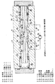
【実 施 例】
図3に示すように、弁本体50には弁孔51が形成され、その弁孔51には第1・第2ポンプ側ポート52,53と第1・第2モータ側ポート54,55が形成してあり、各ポートは弁孔51に摺動自在に嵌挿したスプール56で連通、遮断され、そのスプール56は一対のバネ57,57で中立位置Nに保持され、かつ左右受圧室58,59の圧油力で図1に示す第1位置A、第2位置Bに向けて摺動される。
【0019】
前記スプール56の左右には軸孔60が穿孔され、この軸孔60はスプール56に穿孔した小径孔61でスプール56の左右小径部62,63にそれぞれ開口し、かつ大径孔64でスプール56の外周面に開口し、各軸孔60は左右受圧室58,59に連通・遮断される。
【0020】
前記第1・第2ポンプ側ポート52,53は図1に示す第1・第2主回路3,4に接続し、第1・第2モータ側ポート54,55は図1に示す油圧モータ5の第1・第2ポート61 ,62 に接続している。
【0021】
次に各部の詳細を作動とともに説明する。
図1に示す操作弁2が中立位置Nの時にはカウンタバランス弁7は中立位置Nとなって、そのスプール56は図3の中立位置となり、大径孔64は弁孔51で閉塞されている。
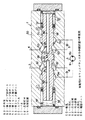
この状態から、操作弁2を第1位置aとすると、油圧ポンプ1の吐出圧油が第1主回路3に供給され、第1主回路3の圧油は第1ポンプ側ポート52、小径孔61、軸孔60より左受圧室58に流れてスプール56を右方にL3 だけ押して図4に示す走行位置とし、第2ポンプ側ポート53と第2モータ側ポート55を右小径部63で連通し、左側の大径孔64は弁孔51に形成した補助ポート65に開口する。
【0022】
これにより、油圧モータ5の第1ポート61 に圧油が供給され、第2ポート62 より圧油が第2モータ側ポート55、第2ポンプ側ポート53を通ってタンク9に流出する。
なお、前記補助ポート65は油圧モータ5を制動するブレーキを解除作動する油圧回路に接続している。
【0023】
前述の状態より操作弁2を中立位置Nとすると第1主回路3内の圧油がタンク9に流出して圧力が低下するので、スプール56はバネ57で左方に向けて摺動する。
【0024】
この時、左受圧室58内の圧油は、図4に示すように軸孔60、小径孔61より第1ポンプ側ポート52に流れ、第1主回路3よりタンク9に流出すると共に、軸孔60、大径孔64より補助ポート65に流出するので、左受圧室58内の圧油の流出経路の絞り用開口面積は第1小径孔61の開口面積と大径孔64の開口面積の和となって大であるから左受圧室58内の圧油がスムーズに流出し、スプール56は高速で摺動するので、キャビテーションを防止し、追従性良く減速する。
【0025】
そして、スプール56がL4 だけ左方にストロークして中間位置となると図5のように、大径孔64が弁孔51で閉塞され、左受圧室58の圧油は軸孔60と小径孔61で第1ポンプ側ポート52に流出し、その流出経路の開口面積は小径孔61の開口面積のみで小となり、左受圧室58内の圧油はタンク9に徐々に流出し、スプール56がL5 だけ左方にストロークすると図3に示す中立位置となるので、スプール56は低速で左方に摺動するから、停止ショックは小さく、ダンピング効果も大きくハンチングを抑制する。
【0026】
このように、カウンタバランス弁7のスプール56は走行位置より中立位置に摺動する際に中間位置までのストローク初期には高速で摺動し、中間位置から中立位置までのストローク終期には低速で摺動するので、カウンタバランス弁7が高速で摺動するストローク初期にキャビテーションを防止でき、低速で摺動するストローク終期にショックなく減速して中立位置に停止できる。
【0027】
したがって、キャビテーションを防止しながらショックなく減速して停止できると共に、短時間にスプール56を中立位置として短時間に停止できる。
【0028】
【発明の効果】
スプール56が走行位置より中立位置に向けて移動する時に、中間位置までのストローク初期には左右受圧室58,59内の圧油が小径孔61と大径孔64よりスムーズに流出し、さらに中立位置までストロークする時には小径孔61のみより流出して流れ難くなるので、スプール56の移動速度はストローク初期には速く、ストローク終期では遅くなり、キャビテーションを防止しながらスプール56を短時間に中立位置に復帰できると共に、第2・第1モータ側ポート55,54を第2・第1ポンプ側ポート53,52に徐々に連通できる。
したがって、油圧モータの駆動油圧回路に設けることでキャビテーションを防止しながらショックなく減速して短時間に油圧モータを停止できる。
また、弁本体50とスプール56より構成したので、部品点数が少なくコストが安くなるし、組立作業が容易となる。
【図面の簡単な説明】
【図1】従来の駆動油圧回路図である。
【図2】従来のカウンタバランス弁の断面図である。
【図3】本発明のカウンタバランス弁の中立状態の断面図である。
【図4】本発明のカウンタバランス弁の走行状態の断面図である。
【図5】本発明のカウンタバランス弁の中間状態の断面図である。
【符号の説明】
50…弁本体
52…第1ポンプ側ポート
53…第2ポンプ側ポート
54…第1モータ側ポート
55…第2モータ側ポート
56…スプール
57…バネ
58…左受圧室
59…右受圧室
60…軸孔
61…小径孔
62…左小径部
63…右小径部
64…大径孔
65…補助ポート。[0001]
[Industrial applications]
The present invention relates to a counterbalance valve provided in a drive hydraulic circuit of a hydraulic motor used for a traveling device of a construction machine or the like.
[0002]
[Prior art]
FIG. 1 shows an example of a drive hydraulic circuit for a hydraulic motor.
That is, the connection of the discharge path 1a of the
[0003]
The counterbalance valve 7 used in such a drive hydraulic circuit switches to the first and second positions A and B with the high-pressure oil of the first and second
On the other hand, when the
[0004]
For this reason, when the
In order to reduce the shock at the time of stop, the speed at which the counter balance valve 7 returns from the first and second positions A and B to the neutral position N is reduced, and the pressure in the first and second
For example, throttles 11 and 11 are provided in
[0005]
However, in this case, the time required for the counter balance valve 7 to return to the neutral position N is delayed, causing cavitation or prolonging the stop time of the hydraulic motor.
[0006]
As a counterbalance valve for solving this problem, for example, a counterbalance valve disclosed in Japanese Utility Model Laid-Open No. 4-138103 is known.
In other words, as shown in FIG. 2, a spool 26 for communicating / blocking the first and second pump-side ports 22 and 23 and the first and second motor-side ports 24 and 25 in the valve hole 21 of the
[0007]
Shaft holes 30 are respectively formed on the left and right sides of the spool 26, and the shaft holes 30 are respectively opened to the left and right
[0008]
The spool 26 is hole 38 when the neutral position shown in FIG. 2 is closed at the shaft hole 30, hole 38 is closed by the shaft hole 30 when the intermediate position the spool 26 has a predetermined stroke l 2 sliding to the left and right from a neutral position , holes 38 when the running position by a predetermined stroke l 1 sliding in the left and right spool 26 further has an opening on the left and right
[0009]
With such a counterbalance valve, when traveling with the
[0010]
At this time, the pressure oil in the left
[0011]
When the spool 26 is an intermediate position in the stroke to the left by l 1, radial bore 38 is closed at the shaft hole 30, the left
[0012]
Thus, when the spool 26 of the counterbalance valve 7 slides from the running position to the neutral position, it slides at a high speed at the beginning of the stroke from the intermediate position to the intermediate position, and at a low speed at the end of the stroke from the neutral position to the neutral position. Since the counterbalance valve 7 slides, cavitation can be prevented at the beginning of a stroke in which the counterbalance valve 7 slides at a high speed, and the counterbalance valve 7 can be decelerated and stopped at a neutral position at the end of a stroke in which the counterbalance valve 7 slides at a low speed.
[0013]
Therefore, the counterbalance valve described above can be decelerated and stopped without shock while preventing cavitation, and the spool 26 can be stopped in a short time by setting the spool 26 to the neutral position.
[0014]
[Problems to be solved by the invention]
Such a counterbalance valve is composed of the
Moreover, the piston 31 has the
[0015]
Therefore, an object of the present invention is to provide a counterbalance valve capable of solving the above-mentioned problem.
[0016]
[Means for Solving the Problems]
The
The
When the
[0017]
[Operation]
When the
Further, since the
[0018]
【Example】
As shown in FIG. 3, a
[0019]
Shaft holes 60 are drilled on the left and right sides of the
[0020]
The first and second pump-
[0021]
Next, the details of each part will be described together with the operation.
When the
In this state, when the
[0022]
Thus, pressure oil is supplied to the first port 6 1 of the
The
[0023]
When the
[0024]
At this time, the pressure oil in the left
[0025]
Then, as shown in FIG. 5 when the
[0026]
Thus, when the
[0027]
Therefore, it is possible to decelerate and stop without shock while preventing cavitation, and to quickly stop the
[0028]
【The invention's effect】
When the
Therefore, by providing the hydraulic circuit for driving the hydraulic motor, the hydraulic motor can be decelerated without a shock and stopped in a short time while preventing cavitation.
Further, since the
[Brief description of the drawings]
FIG. 1 is a diagram of a conventional drive hydraulic circuit.
FIG. 2 is a sectional view of a conventional counterbalance valve.
FIG. 3 is a sectional view of a neutral state of the counterbalance valve of the present invention.
FIG. 4 is a sectional view of a running state of the counterbalance valve of the present invention.
FIG. 5 is a sectional view of an intermediate state of the counterbalance valve of the present invention.
[Explanation of symbols]
50 ...
Claims (2)
前記スプール56に、左受圧室58に連通した第1の軸孔60と右受圧室59に連通した第2の軸孔60及び、その第1・第2の軸孔60を常時第1・第2ポンプ側ポート52,53にそれぞれ連通する第1・第2の小径孔61並びに、第1・第2の軸孔60をスプール外周面に開口する第1・第2の大径孔64をそれぞれ形成し、前記弁本体50に補助ポート65を形成し、
前記スプール56が中立位置及び中立位置と第1・第2の走行位置の中間位置の時には第1・第2の大径孔64が閉塞され、スプール56が第1の走行位置の時には第1の大径孔64が補助ポート65に連通し、スプール56が第2の走行位置の時には第2の大径孔64が補助ポート65に連通する構成としたことを特徴とするカウンタバランス弁。The valve body 50 is provided with a spool 56 that allows the first and second pump-side ports 52 and 53 to communicate with and shuts off the first and second motor-side ports 54 and 55 slidably to the left and right. The left and right springs 57, 57 are held at the neutral position to shut off, and are moved to the first traveling position where the second pump side port 53 and the second motor side port 55 communicate with each other by the pressurized oil in the left pressure receiving chamber 58. The pressure oil in the pressure receiving chamber 59 moves to a second traveling position where the first pump side port 52 and the first motor side port 54 communicate with each other,
The first shaft hole 60 communicating with the left pressure receiving chamber 58 and the second shaft hole 60 communicating with the right pressure receiving chamber 59, and the first and second shaft holes 60 are always connected to the spool 56 by the first and second shaft holes. First and second small-diameter holes 61 communicating with the pump-side ports 52 and 53, and first and second large-diameter holes 64 opening the first and second shaft holes 60 on the outer peripheral surface of the spool, respectively. Forming an auxiliary port 65 in the valve body 50;
When the spool 56 is at the neutral position or at an intermediate position between the neutral position and the first and second traveling positions, the first and second large-diameter holes 64 are closed, and when the spool 56 is at the first traveling position, the first and second large-diameter holes 64 are closed. A counterbalance valve, wherein the large-diameter hole 64 communicates with the auxiliary port 65, and the second large-diameter hole 64 communicates with the auxiliary port 65 when the spool 56 is in the second running position.
スプール56が中立位置の時には第1・第2の大径孔64が弁本体20により閉塞され、スプール56が中立位置から左右に所定ストローク移動すると第1又は第2の大径孔64が補助ポート65に連通するようにした請求項1記載のカウンタバランス弁。An auxiliary port 65 is formed at an intermediate position between the first pump-side port 52 and the second pump-side port 53, and a left small-diameter portion 62 that disconnects the spool 56 from the first pump-side port 52 and the first motor-side port 54. A right small-diameter portion 63 is formed to communicate and shut off the second pump-side port 53 and the second motor-side port 55, and first and second small-diameter holes 61 are opened in the left and right small-diameter portions 62, 63, respectively. -The second large-diameter hole 64 is positioned closer to the auxiliary port 65 than the small-diameter hole 61,
When the spool 56 is in the neutral position, the first and second large-diameter holes 64 are closed by the valve body 20, and when the spool 56 moves a predetermined stroke from the neutral position to the left and right, the first or second large-diameter hole 64 is connected to the auxiliary port. The counterbalance valve according to claim 1, wherein the counterbalance valve communicates with the valve.
Priority Applications (7)
| Application Number | Priority Date | Filing Date | Title |
|---|---|---|---|
| JP25212694A JP3549124B2 (en) | 1994-10-18 | 1994-10-18 | Counter balance valve |
| KR1019950035640A KR960014733A (en) | 1994-10-18 | 1995-10-16 | Counter Balance Valve |
| US08/817,414 US6068013A (en) | 1994-10-18 | 1995-10-18 | Counter balance valve |
| EP95934832A EP0787904B1 (en) | 1994-10-18 | 1995-10-18 | Counter-balance valve |
| PCT/JP1995/002135 WO1996012110A1 (en) | 1994-10-18 | 1995-10-18 | Counter-balance valve |
| DE69517437T DE69517437T2 (en) | 1994-10-18 | 1995-10-18 | COMPENSATING VALVE |
| CN95196478A CN1166870A (en) | 1994-10-18 | 1995-10-18 | Counter-balance valve |
Applications Claiming Priority (1)
| Application Number | Priority Date | Filing Date | Title |
|---|---|---|---|
| JP25212694A JP3549124B2 (en) | 1994-10-18 | 1994-10-18 | Counter balance valve |
Publications (2)
| Publication Number | Publication Date |
|---|---|
| JPH08121405A JPH08121405A (en) | 1996-05-14 |
| JP3549124B2 true JP3549124B2 (en) | 2004-08-04 |
Family
ID=17232841
Family Applications (1)
| Application Number | Title | Priority Date | Filing Date |
|---|---|---|---|
| JP25212694A Expired - Lifetime JP3549124B2 (en) | 1994-10-18 | 1994-10-18 | Counter balance valve |
Country Status (7)
| Country | Link |
|---|---|
| US (1) | US6068013A (en) |
| EP (1) | EP0787904B1 (en) |
| JP (1) | JP3549124B2 (en) |
| KR (1) | KR960014733A (en) |
| CN (1) | CN1166870A (en) |
| DE (1) | DE69517437T2 (en) |
| WO (1) | WO1996012110A1 (en) |
Families Citing this family (14)
| Publication number | Priority date | Publication date | Assignee | Title |
|---|---|---|---|---|
| US6923289B1 (en) | 2003-09-11 | 2005-08-02 | Sauer-Danfoss, Inc. | Closed circuit steering circuit for mobile vehicles |
| CN102619798B (en) * | 2011-01-26 | 2015-05-20 | 南京工程学院 | High-frequency hydraulic rotating valve |
| CN102562699B (en) * | 2011-12-16 | 2014-04-30 | 中联重科股份有限公司 | Balanced valve, hydraulic cylinder expansion control loop and crane |
| CN102562920B (en) * | 2012-01-20 | 2014-01-22 | 河海大学常州校区 | Proportional main-control hydraulic rotary damper |
| CN102562904B (en) * | 2012-01-20 | 2014-04-16 | 河海大学常州校区 | Main-control hydraulic rotary damper |
| CN103016596B (en) * | 2012-12-10 | 2014-08-27 | 河海大学常州校区 | Speed sensitive hydraulic rotary damper |
| CN102992135B (en) * | 2012-12-10 | 2015-03-11 | 河海大学常州校区 | Hydraulic speed limiter for elevator |
| CN104747523B (en) * | 2015-04-02 | 2017-03-15 | 武汉船用机械有限责任公司 | A kind of lowering velocity limits hydraulic control valve |
| CN104912866B (en) * | 2015-06-29 | 2017-05-10 | 宁波精垦液压有限公司 | A compact type fully hydraulic walking pile-up valve |
| CN106870499B (en) * | 2017-04-28 | 2018-12-21 | 太原科技大学 | A kind of damping buffering valve |
| JP6931308B2 (en) * | 2017-09-26 | 2021-09-01 | 川崎重工業株式会社 | Anti-sway device |
| US10801523B2 (en) * | 2017-11-08 | 2020-10-13 | Clark Equipment Company | Hydraulic circuit for travel motor |
| CN109826839A (en) * | 2019-03-29 | 2019-05-31 | 潍柴动力股份有限公司 | A kind of rotary motor counnter attack rotary valve and engineering machinery |
| CN110552928A (en) * | 2019-09-24 | 2019-12-10 | 江苏徐工工程机械研究院有限公司 | Integrated valve and floating hydraulic system |
Family Cites Families (10)
| Publication number | Priority date | Publication date | Assignee | Title |
|---|---|---|---|---|
| US2837106A (en) * | 1955-02-18 | 1958-06-03 | Russell E Bauer | Lock valve |
| CH568487A5 (en) * | 1973-08-08 | 1975-10-31 | Cyphelly Ivan J | |
| US4114516A (en) * | 1976-10-15 | 1978-09-19 | Caterpillar Tractor Co. | Anti-cavitation and pressure modulating relief valve for controlling hydraulic cylinders |
| DE3151027A1 (en) * | 1981-12-23 | 1983-07-28 | Robert Bosch Gmbh, 7000 Stuttgart | Hydraulic control arrangement for a servomotor |
| JPS58146167A (en) * | 1982-02-24 | 1983-08-31 | Nec Corp | Message service system of incoming signal |
| JPS58146167U (en) * | 1982-03-26 | 1983-10-01 | カヤバ工業株式会社 | double counterbalance valve |
| JPH0329649Y2 (en) * | 1984-09-13 | 1991-06-24 | ||
| JPH0221659Y2 (en) * | 1984-10-15 | 1990-06-11 | ||
| JP2603868B2 (en) * | 1989-04-24 | 1997-04-23 | 株式会社小松製作所 | Counter balance valve |
| JPH04138103A (en) * | 1990-09-28 | 1992-05-12 | Sekisui Chem Co Ltd | Kitchen-use housing case |
-
1994
- 1994-10-18 JP JP25212694A patent/JP3549124B2/en not_active Expired - Lifetime
-
1995
- 1995-10-16 KR KR1019950035640A patent/KR960014733A/en active IP Right Grant
- 1995-10-18 US US08/817,414 patent/US6068013A/en not_active Expired - Lifetime
- 1995-10-18 EP EP95934832A patent/EP0787904B1/en not_active Expired - Lifetime
- 1995-10-18 CN CN95196478A patent/CN1166870A/en active Pending
- 1995-10-18 WO PCT/JP1995/002135 patent/WO1996012110A1/en active IP Right Grant
- 1995-10-18 DE DE69517437T patent/DE69517437T2/en not_active Expired - Lifetime
Also Published As
| Publication number | Publication date |
|---|---|
| US6068013A (en) | 2000-05-30 |
| EP0787904A4 (en) | 1997-12-17 |
| WO1996012110A1 (en) | 1996-04-25 |
| DE69517437D1 (en) | 2000-07-13 |
| JPH08121405A (en) | 1996-05-14 |
| EP0787904A1 (en) | 1997-08-06 |
| CN1166870A (en) | 1997-12-03 |
| EP0787904B1 (en) | 2000-06-07 |
| KR960014733A (en) | 1996-05-22 |
| DE69517437T2 (en) | 2001-02-08 |
Similar Documents
| Publication | Publication Date | Title |
|---|---|---|
| JP3549124B2 (en) | Counter balance valve | |
| JP2603868B2 (en) | Counter balance valve | |
| US4520625A (en) | Hydraulic brake valve system | |
| US5884984A (en) | Hydraulic braking apparatus having two safety valves | |
| JP3508955B2 (en) | Hydraulic motor drive | |
| KR980701069A (en) | Brake Device for a Hydraulic Motor | |
| EP3421819B1 (en) | Anti-cavitation hydraulic circuit | |
| US5335495A (en) | Brake valve | |
| US7069723B2 (en) | Anti-reaction valve device, and control unit and hydraulically powered system comprising anti-reaction valve device | |
| JP2537617Y2 (en) | Counter balance valve | |
| JP3622822B2 (en) | Counter balance valve | |
| JP4325851B2 (en) | HST travel drive device | |
| JPH03163225A (en) | Directional control valve | |
| JP2558115Y2 (en) | Valve device | |
| JPH0329649Y2 (en) | ||
| JP4610116B2 (en) | Valve device | |
| JPH0744802Y2 (en) | Pressure control valve | |
| JP3855000B2 (en) | Hydraulic drive | |
| JPH0210322Y2 (en) | ||
| JP4633393B2 (en) | Anti-cavitation hydraulic circuit | |
| JPS62242102A (en) | Driving circuit for oil hydraulic motor | |
| JP3734639B2 (en) | Absorption control device for variable displacement axial piston motor | |
| JP3220263B2 (en) | Check valve | |
| JPH077601Y2 (en) | Confluence controller | |
| JPH0712721Y2 (en) | Hydraulic actuator |
Legal Events
| Date | Code | Title | Description |
|---|---|---|---|
| TRDD | Decision of grant or rejection written | ||
| A01 | Written decision to grant a patent or to grant a registration (utility model) |
Free format text: JAPANESE INTERMEDIATE CODE: A01 Effective date: 20040414 |
|
| A61 | First payment of annual fees (during grant procedure) |
Free format text: JAPANESE INTERMEDIATE CODE: A61 Effective date: 20040416 |
|
| R150 | Certificate of patent or registration of utility model |
Free format text: JAPANESE INTERMEDIATE CODE: R150 |
|
| FPAY | Renewal fee payment (event date is renewal date of database) |
Free format text: PAYMENT UNTIL: 20090430 Year of fee payment: 5 |
|
| FPAY | Renewal fee payment (event date is renewal date of database) |
Free format text: PAYMENT UNTIL: 20100430 Year of fee payment: 6 |
|
| FPAY | Renewal fee payment (event date is renewal date of database) |
Free format text: PAYMENT UNTIL: 20100430 Year of fee payment: 6 |
|
| FPAY | Renewal fee payment (event date is renewal date of database) |
Free format text: PAYMENT UNTIL: 20110430 Year of fee payment: 7 |
|
| FPAY | Renewal fee payment (event date is renewal date of database) |
Free format text: PAYMENT UNTIL: 20110430 Year of fee payment: 7 |
|
| FPAY | Renewal fee payment (event date is renewal date of database) |
Free format text: PAYMENT UNTIL: 20120430 Year of fee payment: 8 |
|
| FPAY | Renewal fee payment (event date is renewal date of database) |
Free format text: PAYMENT UNTIL: 20130430 Year of fee payment: 9 |
|
| FPAY | Renewal fee payment (event date is renewal date of database) |
Free format text: PAYMENT UNTIL: 20130430 Year of fee payment: 9 |
|
| FPAY | Renewal fee payment (event date is renewal date of database) |
Free format text: PAYMENT UNTIL: 20140430 Year of fee payment: 10 |
|
| EXPY | Cancellation because of completion of term |