EP0787864A1 - Sanitary security device - Google Patents
Sanitary security device Download PDFInfo
- Publication number
- EP0787864A1 EP0787864A1 EP96120231A EP96120231A EP0787864A1 EP 0787864 A1 EP0787864 A1 EP 0787864A1 EP 96120231 A EP96120231 A EP 96120231A EP 96120231 A EP96120231 A EP 96120231A EP 0787864 A1 EP0787864 A1 EP 0787864A1
- Authority
- EP
- European Patent Office
- Prior art keywords
- safety device
- cartridge
- cartridge housing
- designed
- backflow preventer
- Prior art date
- Legal status (The legal status is an assumption and is not a legal conclusion. Google has not performed a legal analysis and makes no representation as to the accuracy of the status listed.)
- Granted
Links
- XLYOFNOQVPJJNP-UHFFFAOYSA-N water Substances O XLYOFNOQVPJJNP-UHFFFAOYSA-N 0.000 claims abstract description 49
- 238000010168 coupling process Methods 0.000 claims description 31
- 238000005859 coupling reaction Methods 0.000 claims description 31
- 230000008878 coupling Effects 0.000 claims description 30
- 238000007789 sealing Methods 0.000 claims description 15
- 238000003780 insertion Methods 0.000 claims description 7
- 230000037431 insertion Effects 0.000 claims description 7
- 238000000926 separation method Methods 0.000 claims description 4
- 230000002093 peripheral effect Effects 0.000 claims description 3
- 238000011144 upstream manufacturing Methods 0.000 description 6
- 238000004519 manufacturing process Methods 0.000 description 3
- 239000004033 plastic Substances 0.000 description 3
- 238000010992 reflux Methods 0.000 description 3
- 210000004905 finger nail Anatomy 0.000 description 2
- 230000006978 adaptation Effects 0.000 description 1
- 238000004873 anchoring Methods 0.000 description 1
- 238000010276 construction Methods 0.000 description 1
- 238000006073 displacement reaction Methods 0.000 description 1
- 230000000694 effects Effects 0.000 description 1
- 238000002347 injection Methods 0.000 description 1
- 239000007924 injection Substances 0.000 description 1
- 230000003993 interaction Effects 0.000 description 1
- 239000002245 particle Substances 0.000 description 1
- 230000000284 resting effect Effects 0.000 description 1
- 239000000243 solution Substances 0.000 description 1
- 230000002195 synergetic effect Effects 0.000 description 1
Images


Classifications
-
- E—FIXED CONSTRUCTIONS
- E03—WATER SUPPLY; SEWERAGE
- E03C—DOMESTIC PLUMBING INSTALLATIONS FOR FRESH WATER OR WASTE WATER; SINKS
- E03C1/00—Domestic plumbing installations for fresh water or waste water; Sinks
- E03C1/02—Plumbing installations for fresh water
- E03C1/10—Devices for preventing contamination of drinking-water pipes, e.g. means for aerating self-closing flushing valves
- E03C1/106—Devices for preventing contamination of drinking-water pipes, e.g. means for aerating self-closing flushing valves using two or more check valves
-
- E—FIXED CONSTRUCTIONS
- E03—WATER SUPPLY; SEWERAGE
- E03C—DOMESTIC PLUMBING INSTALLATIONS FOR FRESH WATER OR WASTE WATER; SINKS
- E03C1/00—Domestic plumbing installations for fresh water or waste water; Sinks
- E03C1/02—Plumbing installations for fresh water
- E03C1/08—Jet regulators or jet guides, e.g. anti-splash devices
-
- E—FIXED CONSTRUCTIONS
- E03—WATER SUPPLY; SEWERAGE
- E03C—DOMESTIC PLUMBING INSTALLATIONS FOR FRESH WATER OR WASTE WATER; SINKS
- E03C1/00—Domestic plumbing installations for fresh water or waste water; Sinks
- E03C1/02—Plumbing installations for fresh water
- E03C2001/026—Plumbing installations for fresh water with flow restricting devices
-
- Y—GENERAL TAGGING OF NEW TECHNOLOGICAL DEVELOPMENTS; GENERAL TAGGING OF CROSS-SECTIONAL TECHNOLOGIES SPANNING OVER SEVERAL SECTIONS OF THE IPC; TECHNICAL SUBJECTS COVERED BY FORMER USPC CROSS-REFERENCE ART COLLECTIONS [XRACs] AND DIGESTS
- Y10—TECHNICAL SUBJECTS COVERED BY FORMER USPC
- Y10T—TECHNICAL SUBJECTS COVERED BY FORMER US CLASSIFICATION
- Y10T137/00—Fluid handling
- Y10T137/7504—Removable valve head and seat unit
-
- Y—GENERAL TAGGING OF NEW TECHNOLOGICAL DEVELOPMENTS; GENERAL TAGGING OF CROSS-SECTIONAL TECHNOLOGIES SPANNING OVER SEVERAL SECTIONS OF THE IPC; TECHNICAL SUBJECTS COVERED BY FORMER USPC CROSS-REFERENCE ART COLLECTIONS [XRACs] AND DIGESTS
- Y10—TECHNICAL SUBJECTS COVERED BY FORMER USPC
- Y10T—TECHNICAL SUBJECTS COVERED BY FORMER US CLASSIFICATION
- Y10T137/00—Fluid handling
- Y10T137/7722—Line condition change responsive valves
- Y10T137/7837—Direct response valves [i.e., check valve type]
- Y10T137/7904—Reciprocating valves
- Y10T137/7922—Spring biased
- Y10T137/7929—Spring coaxial with valve
- Y10T137/7932—Valve stem extends through fixed spring abutment
- Y10T137/7933—Yoke or cage-type support for valve stem
Definitions
- the invention relates to a sanitary safety device which is interposed in a water pipe and can be inserted there in the area of a coupling or disconnection point on the mouth side.
- a flexible water hose is already known from EP 0 566 813, the hose connection of which on the mouth side has a recess into which a flow limiter can be inserted. Since the known water hose already has a flow limiter in its hose connection, there is no need for such a limiter in the area of the water fittings and mixers, where it can influence the structure of these fittings and can lead to difficulties in their manufacture, assembly and use.
- the known flow restrictor can also be used in connection with a backflow preventer.
- the adaptation of the recess provided in the hose connection to the longitudinal extent of the flow restrictor on the one hand and of the backflow preventer on the other hand defines the functions of the known water hose.
- the flow limiter and the backflow preventer have to be laboriously separate when installing the hose are inserted into the recess, which can be associated with incorrect assembly and a not inconsiderable additional effort.
- the sanitary safety device has a flow rate regulator, flow limiter or similar throttle and at least one backflow preventer, which are combined in the sanitary safety device to form a unit designed as an insert cartridge.
- a flow regulator or the like with at least one backflow preventer is combined to form a unit which is designed as an insert cartridge or insert cartridge and can be inserted in a simple manner and with little effort at the coupling or separation point of a water line on the mouth side. Incorrect assembly can be counteracted by an appropriate design of the cartridge housing and / or by an appropriate marking on its peripheral jacket.
- the cartridge not only combines the advantages of the components summarized in it, namely the water saving effect of the flow regulator and the backflow stop of dirty service water into the mains, especially in the area of flexible water hoses, by means of the backflow preventer. Rather, the insert cartridge can also be used advantageously where there is a dominant water pressure on the fitting and in particular on a single-lever mixer as a result of strongly fluctuating water pressures in the hot or cold water area.
- the backflow preventer prevents hot water from entering the cold water area of the supply network due to a dominant water pressure in the hot water area and causing further damage to the Part of non-heat-resistant plastic existing water consumer, such as a cistern, can lead.
- An advantageous embodiment according to the invention provides that the backflow preventer of the cartridge in the flow direction of the flow rate controller and the flow rate controller may be preceded by the front screen. Since the flow regulator regulates high liter capacities, higher flow velocities often occur downstream of the flow regulator, which can be reduced in the flow-back check valve on the other hand in such a way that less noise-producing turbulence occurs here.
- attachment screen is connected upstream of the flow regulator of the cartridge in the direction of flow of the non-return valve and the non-return valve.
- the arrangement of the flow regulator and the backflow preventer in an insert cartridge allows only the flow regulator or only the one for certain areas of application To accommodate backflow preventer in the cartridge without, for example, another water hose or a different hose connection would have to be used.
- the flow regulator, the backflow preventer and, if appropriate, also the front screen are designed as separate, possibly also interchangeable functional inserts which are arranged in a common cartridge housing.
- the front screen it is also possible for it to be releasably connected or connected to the functional insert arranged in the cartridge housing on the inflow side.
- a preferred embodiment according to the invention which is associated with low manufacturing outlay, provides that the inflow-side end face of the cartridge housing is designed as a front screen.
- the front screen is integrally connected to the cartridge housing and can be produced together with this, for example, as a plastic injection molded part.
- a support is provided on the inner wall of the cartridge housing for the flow rate regulator and / or the backflow preventer and, if appropriate, also for the front screen.
- a preferred embodiment according to the invention provides that the supports are arranged offset from one another and are preferably designed as ring collars arranged offset from one another in steps. In particular when the supports are staggered in the direction of flow, the functional inserts are seated sufficiently firmly in the cartridge housing to withstand high water pressure.
- the space remaining between the outer jacket of the cartridge housing on the one hand and the inner wall of the water pipe on the other hand at least one ring seal is sealed. This ring seal prevents a partial flow past the cartridge from flowing through the gap.
- the ring seal can be designed, for example, as a sealing ring which is arranged and underlaid between a stop flange of the cartridge housing on the one hand and an orifice-side end face of a coupling part.
- a sealing ring is provided as an annular seal on the downstream end region of the cartridge housing, the sealing ring being able to be arranged, for example, in an annular groove in the outer cartridge housing shell.
- the cartridge housing can be designed with a housing diameter that also allows the cartridge to be installed in the existing corner valves or similar coupling points.
- a coupling part in particular on the outflow side opposite the corner valve, has a recess designed as a cartridge receptacle on the mouth side.
- an insertion stop is provided on the inflow-side end region of the cartridge housing, which acts on the muzzle-side end face of the coupling part.
- the cartridge can thus be inserted into the recess of the coupling part up to its insertion stop, in order to then close the water pipe again by screwing the coupling parts provided at the coupling or separation point.
- the simple handling and in particular the easy removal of the insert cartridge is favored if, on the circumferential edge or circumferential surface of the insertion stop, which is preferably designed as a ring flange, there is a point of attack for a tool A fingernail or the like is provided and if the point of attack, which is designed in particular as an annular groove-shaped shoulder, is expediently limited by the end face of a coupling part on the mouth side.
- the point of attack which is designed in particular as an annular groove-shaped shoulder
- the insert cartridge is provided in the area of a flexible water pipe, such as is connected upstream of a shower head or similar flexible water outlet.
- a preferred development according to the invention provides that the cartridge housing is detachably but captively held in the recess of the coupling part which is designed as a cartridge receptacle. Since the cartridge housing is detachably held in the cartridge holder, it can be removed or replaced if necessary. The captive hold of the cartridge housing in the cartridge receptacle also ensures that the insert cartridge is not accidentally lost during assembly and cannot perform the intended functions.
- a holding device is provided on the outer circumferential casing of the cartridge housing, preferably on both sides at a distance from the housing ends, which holding device interacts with a counter-holder on the inner wall of the recess and if the connection caused between the holding device and the counter-holder by a rotary movement and / or traction can be overcome.
- the holding device can, for example, be designed as an external thread section provided on the peripheral jacket of the cartridge housing, which cooperates with an internal thread section on the inner wall of the recess.
- a particularly simple and advantageous embodiment according to the invention provides that the holding device or the counter-holder is formed by at least one holding cam, which cooperates with at least one holding lug and that the holding cam and / or the holding lug is formed in a circular manner. Since the holding device is provided at a distance from the housing ends on the cartridge housing, the cartridge housing can first be pushed out of the recess until the holding device strikes the counter-holder. The detachable connection between these parts can then be overcome and the cartridge housing can finally be removed from the cartridge holder by a preferably defined tensile force and / or by a rotary movement of the cartridge housing relative to the coupling part. Although the cartridge is held captive in the cartridge housing, it can be removed and replaced easily and without great effort if required.
- an annular seal provided between the outer casing of the cartridge housing on the one hand and the inner wall of the water line on the other hand could possibly hinder the easy displacement of the cartridge housing in the cartridge receptacle. It can therefore be advantageous here if the cartridge housing can be inserted into the recess as far as a stop and if the cartridge housing preferably has a particularly annular sealing edge which seals the sealing edge in approximately one plane with the upstream end face of the coupling part.
- the space provided between the cartridge housing and the cartridge receptacle can be sealed, for example, by a sealing ring which lies against the inflow-side mouth edge of the coupling part and extends in the radial direction up to the sealing edge of the cartridge housing.
- a flow controller 2 is shown in two different versions, which has a rubber ring 4 or the like elastomeric component, which regulates the clear cross section of the flow controller 2 and thus its liter output per unit of time depending on the water pressure to a defined maximum value.
- the flow regulator 2 is combined with a backflow preventer 3 to form a unit designed as an insert cartridge or insert cartridge 1, which in a recess 5 designed as a cartridge holder is attached to a flexible water hose 6 provided hose connection 7 can be inserted on the mouth side and forms a sanitary safety device.
- the hose connection 7 serves as a coupling part for coupling the water hose 6 to a coupling or disconnection point interposed in the water line.
- the cartridge 1 has on the inflow side a cross section which is approximately W-shaped, which keeps the dirt particles possibly contained in the water flow away from the flow regulator 2 and the backflow preventer 3 and is intended to ensure their undisturbed function.
- the flow regulator 2, the backflow preventer 3 and the front screen 8 are each designed as separate functional inserts and adapted to the shape can be used in a common cartridge housing 9 of the cartridge 1.
- the cartridge housings 9 in FIGS. 1 and 2 each have at least one support 10 designed as an annular collar or ring shoulder, which is provided on the inner wall of the housing in the region of the downstream end region.
- the flow rate controller 2, the backflow preventer 3 and the front screen 8 are of conventional design, although they can also be designed differently from the embodiments shown here.
- the flow rate controller 2 is connected upstream of the backflow preventer 3 and the backflow preventer 3 in the flow direction.
- This embodiment according to FIG. 2 can be particularly useful if the design and production effort associated with the cartridge 1 is to be kept as low as possible.
- the guide pin 13 provided on the valve cone 12 of the non-return valve 3 can, if appropriate, be immersed in a control core of the volume regulator 2 encompassed by the rubber ring 4.
- the intermediate space 15 remaining between the outer jacket of the cartridge housing 9 on the one hand and the inner wall of the water line on the other hand is sealed by means of at least one ring seal, which is designed here as a sealing ring 16 provided on the downstream end region of the cartridge housing 9, which is located in an outer annular groove 17 of the cartridge housing 9.
- a plug-in stop 18 designed here as an annular flange is provided on the inflow-side end region of the cartridge housing 9 and acts on the mouth-side end face of the coupling part provided on the inflow-side hose connection of the water hose 6.
- the insert cartridge 1 can thus be inserted into the recess 5 provided on the hose connection 7 or the like coupling part of the water hose 6 up to the insertion stop 18 on the mouth side.
- an engagement point 19 which is designed as an annular groove-shaped shoulder and which can be easily gripped behind with a fingernail or a tool in order to remove and pull out the insert cartridge 1 from the hose connection 7.
- the arrangement of the flow regulator 2 and the backflow preventer 3 in the cartridge 1 allows for certain Areas of application to accommodate only the flow regulator 2 or only the backflow preventer 3 in connection with the front screen 8 in the cartridge housing 9 without, for example, another flexible water hose 6 or hose connection 7 having to be used.
- the insert cartridge 1 can be interposed in a simple manner and with little effort into the water line also formed by the water hose 6, the insertion stop 18 being clamped between the end faces of the mouth of the coupling parts forming the coupling or separation point.
- FIGS. 4 and 5 and 6 and 7 each show an insert cartridge 1, which - similar to FIGS. 1 to 3 - combine a flow regulator 2 and at least one backflow preventer 3 in a common cartridge housing 9 to form a structural unit.
- the upstream end face of the cartridge housing 9 in FIGS. 4 to 7 is designed as an attachment screen 8.
- the attachment screen 8 thus integrally connected to the cartridge housing 9 in FIGS. 4 to 7 can be produced together with this as a plastic injection-molded part.
- the flow rate regulator 2 and the backflow preventer 3 of the insert cartridges 1 are inserted into the cartridge housing 9 from the open end facing away from the front screen 8 such that the flow rate regulator 2 is preceded by a backflow preventer 3 in the flow direction.
- a guide pin 13 is provided on the valve cone 12, which is adjustable against a restoring force, and can dip into a guide opening in the regulator core 14 of the downstream flow rate regulator 2.
- the insert cartridges 1 according to FIGS. 4 to 7 are therefore also distinguished by a compact and space-saving design.
- a circumferential locking cam 21 is provided in the cartridge 1 according to FIGS. 4 and 5 on the last functional unit 2 in the flow direction, which engages in a locking recess 22 on the inner circumference of the cartridge housing 9 for the positive anchoring of this functional unit.
- the insert cartridges 1 in FIGS. 4 to 7 are also inserted in a recess 5 designed as a cartridge receptacle, which is provided on the mouth side on the hose connection 7 of a flexible water hose 6 serving as a coupling part.
- FIGS. 4 and 5 and 6 and 7 A comparison of FIGS. 4 and 5 and 6 and 7 makes it clear that the insert cartridges 1 shown there are detachable but non-detachable in the recess 5 serving as the cartridge receptacle.
- a holding cam 23 is provided on the cartridge housings 9 of the insert cartridges 1 shown in FIGS. 4 to 7, which rotates in a ring on the cartridge housing 9 and is arranged on both sides at a distance from the housing ends.
- This retaining cam 23 on the cartridge housing 9 interacts with a likewise annular retaining lug on the inner wall of the hose connection 7 delimiting the recess 5. Since the holding cam 23 is provided at a distance from the housing ends on the cartridge housing 9, the cartridge housing 9 shown in FIGS.
- annular sealing edge 25 is provided on the cartridge housing 9, which is formed by a projection 26 which protrudes on the inflow-side end face of the cartridge housing 9 and widens conically outward in the direction of flow.
- the sealing edge 25 is arranged in approximately one plane with the inflow-side end of the hose connection 7, so that a space 15 remaining between the cartridge housing 9 and the recess 5 can be sealed off by a sealing ring provided on the mouth side but not shown here.
- the insert cartridge 1 shown there has two non-return valves 3, which provide double functional reliability of the reflux stop function.
- the flow regulator 2 is arranged between the non-return valves 3 which act counter to the direction of flow.
- the hose connections 7 serving as a coupling part each have an external thread onto which a union nut, not shown here and provided for example on a corner valve or preferably on a fitting outlet, can be screwed on as a counter-coupling part for sealing the water line.
Landscapes
- Health & Medical Sciences (AREA)
- Life Sciences & Earth Sciences (AREA)
- Engineering & Computer Science (AREA)
- Hydrology & Water Resources (AREA)
- Public Health (AREA)
- Water Supply & Treatment (AREA)
- Domestic Plumbing Installations (AREA)
- Window Of Vehicle (AREA)
- Emergency Protection Circuit Devices (AREA)
- Orthopedics, Nursing, And Contraception (AREA)
Abstract
Description
Die Erfindung betrifft eine sanitäre Sicherungseinrichtung, die in eine Wasserleitung zwischengeschaltet und dort im Bereich einer Kupplungs- oder Trennstelle mündungsseitig einschiebbar ist.The invention relates to a sanitary safety device which is interposed in a water pipe and can be inserted there in the area of a coupling or disconnection point on the mouth side.
Aus der EP 0 566 813 ist bereits ein flexibler Wasserschlauch bekannt, dessen Schlauchanschluß mündungsseitig eine Ausnehmung hat, in die ein Durchflußbegrenzer einsetzbar ist. Da der vorbekannte Wasserschlauch bereits in seinem Schlauchanschluß einen Durchflußbegrenzer aufweist, kann auf einen derartigen Begrenzer im Bereich der Wasserarmaturen und Mischer verzichtet werden, wo er die Struktur dieser Armaturen beeinflussen und zu Schwierigkeiten bei der Herstellung, dem Zusammenbau sowie der Anwendung führen kann.A flexible water hose is already known from EP 0 566 813, the hose connection of which on the mouth side has a recess into which a flow limiter can be inserted. Since the known water hose already has a flow limiter in its hose connection, there is no need for such a limiter in the area of the water fittings and mixers, where it can influence the structure of these fittings and can lead to difficulties in their manufacture, assembly and use.
Der vorbekannte Durchflußbegrenzer ist auch in Verbindung mit einem Rückflußverhinderer einsetzbar. Die Anpassung der im Schlauchanschluß vorgesehenen Ausnehmung an die Längserstreckung des Durchflußbegrenzers einerseits und des Rückflußverhinderers andererseits legt die Funktionen des vorbekannten Wasserschlauches jedoch fest. Zudem müssen der Durchflußbegrenzer sowie der Rückflußverhinderer bei der Schlauchmontage umständlich einzeln in die Ausnehmung eingesetzt werden, womit Fehlmontagen und ein nicht unerheblicher Mehraufwand verbunden sein können.The known flow restrictor can also be used in connection with a backflow preventer. However, the adaptation of the recess provided in the hose connection to the longitudinal extent of the flow restrictor on the one hand and of the backflow preventer on the other hand defines the functions of the known water hose. In addition, the flow limiter and the backflow preventer have to be laboriously separate when installing the hose are inserted into the recess, which can be associated with incorrect assembly and a not inconsiderable additional effort.
Es besteht daher insbesondere die Aufgabe, eine sanitäre Sicherungseinrichtung der eingangs erwähnten Art zu schaffen, der auf einfache Weise und mit möglichst geringem Aufwand in eine Wasserleitung zwischengeschaltet werden kann.There is therefore in particular the task of creating a sanitary safety device of the type mentioned at the outset, which can be interposed in a water pipe in a simple manner and with as little effort as possible.
Die erfindungsgemäße Lösung dieser Aufgabe besteht bei der sanitären Sicherungseinrichtung insbesondere darin, daß die sanitäre Sicherungseinrichtung einen Durchflußmengenregler, Durchflußbegrenzer oder dergleichen Drossel sowie zumindest einen Rückflußverhinderer aufweist, welche in der sanitären Sicherungseinrichtung zu einer als Einsatzpatrone ausgebildeten Baueinheit zusammengefaßt sind.The solution to this problem according to the invention in the sanitary safety device is, in particular, that the sanitary safety device has a flow rate regulator, flow limiter or similar throttle and at least one backflow preventer, which are combined in the sanitary safety device to form a unit designed as an insert cartridge.
Bei der erfindungsgemäßen Sicherungseinrichtung ist ein Durchflußmengenregler oder dergleichen mit zumindest einem Rückflußverhinderer zu einer als Einsatzpatrone oder Einsatzkartusche ausgebildeten Baueinheit zusammengefaßt, die auf einfache Weise und mit geringem Aufwand an der Kupplungs- oder Trennstelle einer Wasserleitung mündungsseitig einschiebbar ist. Durch eine entsprechende Ausgestaltung des Patronengehäuses und/oder durch eine entsprechende Kennzeichnung an seinem Umfangsmantel können Fehlmontagen entgegengewirkt werden.In the safety device according to the invention, a flow regulator or the like with at least one backflow preventer is combined to form a unit which is designed as an insert cartridge or insert cartridge and can be inserted in a simple manner and with little effort at the coupling or separation point of a water line on the mouth side. Incorrect assembly can be counteracted by an appropriate design of the cartridge housing and / or by an appropriate marking on its peripheral jacket.
Die Einsatzpatrone verbindet nicht nur die Vorteile der in ihr zusammengefaßten Bauteile, nämlich den Wasserspareffekt des Durchflußmengenreglers und den Rückflußstop verschmutzten Brauchwassers in das Leitungsnetz, insbesondere im Bereich flexibler Wasserschläuche, mittels des Rückflußverhinderers. Vielmehr kann die Einsatzpatrone auch dort vorteilhaft eingesetzt werden, wo infolge stark schwankender Wasserdrücke im Warm- oder Kaltwasserbereich ein dominanter Wasserdruck an der Armatur und insbesondere an einem Einhebelmischer anliegt. Während der Durchflußmengenregler in einem solchen Fall die Durchflußmenge pro Zeiteinheit auf einen Höchstwert vergleichmäßigt und das Einregeln und Mischen der gewünschten Wassertemperatur erleichtert, wird mittels dem Rückflußverhinderer verhindert, daß infolge eines dominanten Wasserdrucks im Warmwasserbereich heißes Wasser in den Kaltwasserbereich des Leitungsnetzes übertreten und zu weitergehenden Schäden der zum Teil aus nicht hitzebeständigem Kunststoff bestehenden Wasserverbraucher, beispielsweise eines Spülkastens, führen kann.The cartridge not only combines the advantages of the components summarized in it, namely the water saving effect of the flow regulator and the backflow stop of dirty service water into the mains, especially in the area of flexible water hoses, by means of the backflow preventer. Rather, the insert cartridge can also be used advantageously where there is a dominant water pressure on the fitting and in particular on a single-lever mixer as a result of strongly fluctuating water pressures in the hot or cold water area. During the Flow controller in such a case, the flow rate per unit of time is equalized to a maximum value and the adjustment and mixing of the desired water temperature is facilitated, the backflow preventer prevents hot water from entering the cold water area of the supply network due to a dominant water pressure in the hot water area and causing further damage to the Part of non-heat-resistant plastic existing water consumer, such as a cistern, can lead.
Das somit synergetische Zusammenwirken der in der Einsatzpatrone zusammengefaßten Bauteile kann funktionell gesichert werden, wenn die Einsatzpatrone ein zuströmseitig angeordnetes Vorsatzsieb aufweist.The thus synergetic interaction of the components combined in the insert cartridge can be functionally secured if the insert cartridge has an attachment screen arranged on the inflow side.
Eine vorteilhafte Ausführungsform gemäß der Erfindung sieht vor, daß dem Rückflußverhinderer der Einsatzpatrone in Strömungsrichtung der Durchflußmengenregler und dem Durchflußmengenregler gegebenenfalls das Vorsatzsieb vorgeschaltet ist. Da der Durchflußmengenregler hohe Literleistungen vergleichmäßigt, fallen hinter dem Durchflußmengenregler häufig höhere Strömungsgeschwindigkeiten an, die in dem demgegenüber abströmseitigen Rückflußverhinderer derart reduziert werden können, daß hier geringere geräuschbildende Turbulenzen entstehen.An advantageous embodiment according to the invention provides that the backflow preventer of the cartridge in the flow direction of the flow rate controller and the flow rate controller may be preceded by the front screen. Since the flow regulator regulates high liter capacities, higher flow velocities often occur downstream of the flow regulator, which can be reduced in the flow-back check valve on the other hand in such a way that less noise-producing turbulence occurs here.
Aus Gründen der Geräuschminimierung und im Hinblick auf eine konstruktiv möglichst einfache Ausgestaltung des Erfindungsgegenstandes kann es demgegenüber aber auch zweckmäßig sein, wenn dem Durchflußmengenregler der Einsatzpatrone in Strömungsrichtung der Rückflußverhinderer und dem Rückflußverhinderer gegebenenfalls das Vorsatzsieb vorgeschaltet ist.For reasons of noise minimization and in view of a design of the subject matter of the invention that is as simple as possible in terms of construction, it may also be expedient, however, if the attachment screen is connected upstream of the flow regulator of the cartridge in the direction of flow of the non-return valve and the non-return valve.
Die Anordnung des Durchflußmengenreglers sowie des Rückflußverhinderers in einer Einsatzpatrone erlaubt es, für bestimmte Anwendungsbereiche nur den Durchflußmengenregler oder nur den Rückflußverhinderer in der Einsatzpatrone unterzubringen, ohne daß beispielsweise ein anderer Wasserschlauch oder ein anderer Schlauchanschluß verwendet werden müßte. Zu diesem Zweck kann es vorteilhaft sein, wenn der Durchflußmengenregler, der Rückflußverhinderer sowie gegebenenfalls auch das Vorsatzsieb als separate, gegebenenfalls auch auswechselbare Funktionseinsätze ausgebildet sind, die in einem gemeinsamen Patronengehäuse angeordnet sind.The arrangement of the flow regulator and the backflow preventer in an insert cartridge allows only the flow regulator or only the one for certain areas of application To accommodate backflow preventer in the cartridge without, for example, another water hose or a different hose connection would have to be used. For this purpose, it can be advantageous if the flow regulator, the backflow preventer and, if appropriate, also the front screen are designed as separate, possibly also interchangeable functional inserts which are arranged in a common cartridge housing.
Hinsichtlich des Vorsatzsiebes ist es aber auch möglich, daß dieses mit dem im Patronengehäuse zuströmseitig angeordneten Funktionseinsatz insbesondere lösbar verbindbar oder verbunden ist.With regard to the front screen, however, it is also possible for it to be releasably connected or connected to the functional insert arranged in the cartridge housing on the inflow side.
Eine bevorzugte und mit geringem Herstellungsaufwand verbundene Ausführungsform gemäß der Erfindung sieht vor, daß die zuströmseitige Stirnseite des Patronengehäuses als Vorsatzsieb ausgebildet ist. Bei dieser Ausführungsform ist das Vorsatzsieb einstückig mit dem Patronengehäuse verbunden und kann beispielsweise zusammen mit diesem als Kunststoff-Spritzgußteil hergestellt werden.A preferred embodiment according to the invention, which is associated with low manufacturing outlay, provides that the inflow-side end face of the cartridge housing is designed as a front screen. In this embodiment, the front screen is integrally connected to the cartridge housing and can be produced together with this, for example, as a plastic injection molded part.
Dabei ist es zweckmäßig, wenn an der Innenwand des Patronengehäuses für den Durchflußmengenregler und/oder den Rückflußverhinderer sowie gegebenenfalls auch für das Vorsatzsieb jeweils ein Auflager vorgesehen ist. Eine bevorzugte Ausführungsform gemäß der Erfindung sieht vor, daß die Auflager versetzt zueinander angeordnet und vorzugsweise als stufenförmig versetzt zueinander angeordnete Ringbünde ausgebildet sind. Insbesondere bei einer in Strömungsrichtung stufenförmig versetzten Anordnung der Auflager sitzen die Funktionseinsätze ausreichend fest im Patronengehäuse, um auch einem hohen Wasserdruck standhalten zu können.It is expedient if a support is provided on the inner wall of the cartridge housing for the flow rate regulator and / or the backflow preventer and, if appropriate, also for the front screen. A preferred embodiment according to the invention provides that the supports are arranged offset from one another and are preferably designed as ring collars arranged offset from one another in steps. In particular when the supports are staggered in the direction of flow, the functional inserts are seated sufficiently firmly in the cartridge housing to withstand high water pressure.
Um eine gute Funktionsweise des Erfindungsgegenstandes zu begünstigen, ist es vorteilhaft, wenn der zwischen dem Außenmantel des Patronengehäuses einerseits und der Leitungsinnenwand der Wasserleitung andererseits verbleibende Zwischenraum mittels zumindest einer Ringdichtung abgedichtet ist. Diese Ringdichtung verhindert, daß ein Teilstrom an der Einsatzpatrone vorbei durch den Zwischenraum durchfließen kann.In order to promote good functioning of the subject matter of the invention, it is advantageous if the space remaining between the outer jacket of the cartridge housing on the one hand and the inner wall of the water pipe on the other hand at least one ring seal is sealed. This ring seal prevents a partial flow past the cartridge from flowing through the gap.
Die Ringdichtung kann beispielsweise als Dichtring ausgebildet sein, der zwischen einem Anschlagflansch des Patronengehäuses einerseits und einer mündungsseitigen Stirnfläche eines Kupplungsteiles andererseits angeordnet und untergelegt ist. Um jedoch die Längserstreckung der Einsatzpatrone möglichst kleinzuhalten, ist es vorteilhaft, wenn am abströmseitigen Endbereich des Patronengehäuses ein Dichtring als Ringdichtung vorgesehen ist, wobei der Dichtring beispielsweise in einer Ringnut des äußeren Patronen-Gehäusemantels angeordnet sein kann.The ring seal can be designed, for example, as a sealing ring which is arranged and underlaid between a stop flange of the cartridge housing on the one hand and an orifice-side end face of a coupling part. However, in order to keep the longitudinal extent of the insert cartridge as small as possible, it is advantageous if a sealing ring is provided as an annular seal on the downstream end region of the cartridge housing, the sealing ring being able to be arranged, for example, in an annular groove in the outer cartridge housing shell.
Das Patronengehäuse kann mit einem Gehäusedurchmesser ausgebildet werden, der die Montage der Einsatzpatrone auch in die vorhandenen Eckventile oder dergleichen Kupplungsstellen erlaubt. Bevorzugt wird jedoch eine Weiterbildung gemäß der Erfindung, bei der ein insbesondere gegenüber dem Eckventil abströmseitiges Kupplungsteil mündungsseitig eine als Patronenaufnahme ausgebildete Ausnehmung hat.The cartridge housing can be designed with a housing diameter that also allows the cartridge to be installed in the existing corner valves or similar coupling points. However, a further development according to the invention is preferred in which a coupling part, in particular on the outflow side opposite the corner valve, has a recess designed as a cartridge receptacle on the mouth side.
Damit die Einsatzpatrone auch hohen Wasserdrücken standhalten kann, ist es vorteilhaft, wenn am zuströmseitigen Endbereich des Patronengehäuses ein Einsteckanschlag vorgesehen ist, welcher die mündungsseitige Stirnfläche des Kupplungsteiles beaufschlagt. Die Einsatzpatrone kann somit in die Ausnehmung des Kupplungsteiles bis zu seinem Einsteckanschlag eingeschoben werden, um anschließend die Wasserleitung durch Verschrauben der an der Kupplungs- oder Trennstelle vorgesehenen Kupplungsteile wieder zu schließen.So that the cartridge can withstand high water pressures, it is advantageous if an insertion stop is provided on the inflow-side end region of the cartridge housing, which acts on the muzzle-side end face of the coupling part. The cartridge can thus be inserted into the recess of the coupling part up to its insertion stop, in order to then close the water pipe again by screwing the coupling parts provided at the coupling or separation point.
Die einfache Handhabung und inbesondere der leichte Ausbau der Einsatzpatrone wird begünstigt, wenn am Umfangsrand oder Umfangsmantel des vorzugsweise als Ringflansch ausgebildeten Einsteckanschlages eine Angriffsstelle für ein Werkzeug, einen Fingernagel oder dergleichen vorgesehen ist und wenn die insbesondere als ringnutförmiger Absatz ausgebildete Angriffsstelle zweckmäßigerweise durch die mündungsseitige Stirnfläche eines Kupplungsteiles begrenzt ist. Zum Demontieren der Einsatzpatrone aus der Wasserleitung kann diese somit leicht an der als Ringnut ausgebildeten Angriffsstelle hintergriffen und beispielsweise aus der Ausnehmung des Schlauchanschlusses herausgezogen werden.The simple handling and in particular the easy removal of the insert cartridge is favored if, on the circumferential edge or circumferential surface of the insertion stop, which is preferably designed as a ring flange, there is a point of attack for a tool A fingernail or the like is provided and if the point of attack, which is designed in particular as an annular groove-shaped shoulder, is expediently limited by the end face of a coupling part on the mouth side. To disassemble the cartridge from the water pipe, it can be easily gripped behind at the point of attack designed as an annular groove and, for example, pulled out of the recess of the hose connection.
Besonders vorteilhaft ist es, wenn die Einsatzpatrone im Bereich einer flexiblen Wasserleitung vorgesehen ist, wie sie beispielsweise einem Brausekopf oder dergleichen flexiblem Wasserauslauf vorgeschaltet ist.It is particularly advantageous if the insert cartridge is provided in the area of a flexible water pipe, such as is connected upstream of a shower head or similar flexible water outlet.
Eine bevorzugte Weiterbildung gemäß der Erfindung sieht vor, daß das Patronengehäuse in der als Patronenaufnahme ausgebildeten Ausnehmung des Kupplungsteiles lösbar, aber unverlierbar gehalten ist. Da das Patronengehäuse lösbar in der Patronenaufnahme gehalten ist, kann es bedarfsweise entnommen oder ausgetauscht werden. Durch den unverlierbaren Halt des Patronengehäuses in der Patronenaufnahme wird gleichzeitig sichergestellt, daß die Einsatzpatrone bei der Montage nicht unbeabsichtigt verlorengeht und die beabsichtigten Funktionen nicht erfüllen kann.A preferred development according to the invention provides that the cartridge housing is detachably but captively held in the recess of the coupling part which is designed as a cartridge receptacle. Since the cartridge housing is detachably held in the cartridge holder, it can be removed or replaced if necessary. The captive hold of the cartridge housing in the cartridge receptacle also ensures that the insert cartridge is not accidentally lost during assembly and cannot perform the intended functions.
Dabei ist es vorteilhaft, wenn am äußeren Umfangsmantel des Patronengehäuses vorzugsweise beidseits mit Abstand von den Gehäuseenden eine Halteeinrichtung vorgesehen ist, welche Halteeinrichtung mit einer Gegenhalterung an der Innenwand der Ausnehmung zusammenwirkt und wenn die zwischen der Halteeinrichtung und der Gegenhalterung bewirkte Verbindung durch eine Drehbewegung und/oder Zugkraft überwindbar ist. Die Halteeinrichtung kann beispielsweise als ein am Umfangsmantel des Patronengehäuses vorgesehener Außengewinde-Abschnitt ausgebildet sein, der mit einem Innengewinde-Abschnitt an der Innenwand der Ausnehmung zusammenwirkt. Eine besonders einfache und vorteilhafte Ausführungsform gemäß der Erfindung sieht jedoch vor, daß die Halteeinrichtung oder die Gegenhalterung durch zumindest eine Haltenocke gebildet ist, die mit zumindest einer Haltenase zusammenwirkt und daß die Haltenocke und/oder die Haltenase ringförmig umlaufend ausgebildet ist. Da die Halteeinrichtung mit Abstand von den Gehäuseenden am Patronengehäuse vorgesehen ist, kann das Patronengehäuse zunächst soweit aus der Ausnehmung herausgeschoben werden, bis die Halteeinrichtung an der Gegenhalterung anschlägt. Durch eine vorzugsweise definierte Zugkraft und/oder durch eine Drehbewegung des Patronengehäuses relativ zum Kupplungsteil kann die lösbare Verbindung zwischen diesen Teilen anschließend überwunden und das Patronengehäuse endgültig aus der Patronenaufnahme entnommen werden. Obwohl die Einsatzpatrone unverlierbar im Patronengehäuse gehalten ist, kann diese somit bei Bedarf leicht und ohne größeren Aufwand entnommen und ausgewechselt werden.It is advantageous if a holding device is provided on the outer circumferential casing of the cartridge housing, preferably on both sides at a distance from the housing ends, which holding device interacts with a counter-holder on the inner wall of the recess and if the connection caused between the holding device and the counter-holder by a rotary movement and / or traction can be overcome. The holding device can, for example, be designed as an external thread section provided on the peripheral jacket of the cartridge housing, which cooperates with an internal thread section on the inner wall of the recess. A particularly simple and advantageous embodiment according to the invention, however, provides that the holding device or the counter-holder is formed by at least one holding cam, which cooperates with at least one holding lug and that the holding cam and / or the holding lug is formed in a circular manner. Since the holding device is provided at a distance from the housing ends on the cartridge housing, the cartridge housing can first be pushed out of the recess until the holding device strikes the counter-holder. The detachable connection between these parts can then be overcome and the cartridge housing can finally be removed from the cartridge holder by a preferably defined tensile force and / or by a rotary movement of the cartridge housing relative to the coupling part. Although the cartridge is held captive in the cartridge housing, it can be removed and replaced easily and without great effort if required.
Bei dieser Ausführung könnte ein zwischen dem Außenmantel des Patrönengehäuses einerseits und der Leitungsinnenwand der Wasserleitung andererseits vorgesehene Ringdichtung eventuell die leichte Verschiebbarkeit des Patronengehäuses in der Patronenaufnahme behindern. Hier kann es daher vorteilhaft sein, wenn das Patronengehäuse bis zu einem Anschlag in die Ausnehmung einführbar ist und wenn das Patronengehäuse vorzugsweise einen insbesondere ringförmigen Dichtrand hat, welcher Dichtrand in etwa einer Ebene mit der zuströmseitigen Stirnseite des Kupplungsteiles abschließt. Bei dieser Ausführungsform kann der zwischen dem Patronengehäuse und der Patronenaufnahme vorgesehene Zwischenraum beispielsweise durch einen am zuströmseitigen Mündungsrand des Kupplungsteiles anliegenden und sich in radialer Richtung bis zum Dichtrand des Patronengehäuses erstreckenden Dichtring abgedichtet werden.In this embodiment, an annular seal provided between the outer casing of the cartridge housing on the one hand and the inner wall of the water line on the other hand could possibly hinder the easy displacement of the cartridge housing in the cartridge receptacle. It can therefore be advantageous here if the cartridge housing can be inserted into the recess as far as a stop and if the cartridge housing preferably has a particularly annular sealing edge which seals the sealing edge in approximately one plane with the upstream end face of the coupling part. In this embodiment, the space provided between the cartridge housing and the cartridge receptacle can be sealed, for example, by a sealing ring which lies against the inflow-side mouth edge of the coupling part and extends in the radial direction up to the sealing edge of the cartridge housing.
Um eine doppelte Funktionssicherheit insbesondere bei der Rückfluß-Stopfunktion der erfindungsgemäßen Einsatzpatrone zu erreichen, kann es zweckmäßig sein, wenn im Patronengehäuse wenigstens zwei Rückflußverhinderer vorgesehen sind, zwischen denen ein Durchflußmengenregler angeordnet ist.In order to achieve double functional reliability, in particular in the case of the reflux stop function of the cartridge according to the invention, it may be expedient if at least two reflux preventers are provided in the cartridge housing, between which a flow rate regulator is arranged.
Weitere Merkmale der Erfindung ergeben sich aus der folgenden Beschreibung erfindungsgemäßer Ausführungsbeispiele in Verbindung mit den Ansprüchen sowie der Zeichnung. Die einzelnen Merkmale können je für sich oder zu mehreren bei einer Ausführungsform gemäß der Erfindung verwirklicht sein.Further features of the invention result from the following description of exemplary embodiments according to the invention in conjunction with the claims and the drawing. The individual features can be implemented individually or in groups in one embodiment according to the invention.
Es zeigt:
- Fig. 1
- eine sanitäre Sicherungseinrichtung in einem Teil-Querschnitt, die einen Durchflußmengenregler sowie einen Rückflußverhinderer mit einem zuströmseitigen Vorsatzsieb zu einer als Einsatzpatrone ausgebildeten Baueinheit zusammenfaßt,
- Fig. 2
- eine Einsatzpatrone, ähnlich der aus
Figur 1, wobei hier jedoch der Rückflußverhinderer dem Durchflußmengenregler zuströmseitig vorgeschaltet ist, - Fig. 3
- die Einsatzpatrone aus
Figur 1 oder 2 in der als Patronenaufnahme ausgebildeten Ausnehmung eines an einem flexiblen Wasserschlauch vorgesehenen Schlauchanschlusses, - Fig. 4
- eine Einsatzpatrone, ähnlich der aus Fig. 1, in einer Querschnittsdarstellung,
- Fig. 5
- die Einsatzpatrone aus Fig. 4 in der als Patronenaufnahme ausgebildeten Ausnehmung eines an einem flexiblen Wasserschlauch vorgesehenen Schlauchanschlusses,
- Fig. 6
- eine Einsatzpatrone in einer Querschnittsdarstellung, die in ihrem Patronengehäuse zwei Rückflußverhinderer hat, zwischen denen ein Durchflußmengenregler angeordnet ist und
- Fig. 7
- die Einsatzpatrone aus Fig. 6 in der Patronenaufnahme eines an einem flexiblen Wasserschlauch vorgesehenen Schlauchanschlusses.
- Fig. 1
- a sanitary safety device in a partial cross section, which combines a flow regulator and a backflow preventer with an inflow-side attachment screen to form a unit designed as an insert cartridge,
- Fig. 2
- an insert cartridge, similar to that of Figure 1, but here the backflow preventer is connected upstream of the flow regulator,
- Fig. 3
- 2 the insert cartridge from FIG. 1 or 2 in the recess in the form of a cartridge receptacle of a hose connection provided on a flexible water hose,
- Fig. 4
- an insert cartridge, similar to that of FIG. 1, in a cross-sectional view,
- Fig. 5
- 4 in the recess designed as a cartridge receptacle of a hose connection provided on a flexible water hose,
- Fig. 6
- a cartridge in a cross-sectional view, the two check valves in their cartridge housing has between which a flow regulator is arranged and
- Fig. 7
- 6 in the cartridge receptacle of a hose connection provided on a flexible water hose.
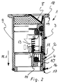
In den Figuren 1 und 2 ist ein Durchflußmengenregler 2 in zwei unterschiedlichen Ausführungen dargestellt, der einen Gummiring 4 oder dergleichen elastomeres Bauteil aufweist, welches den lichten Querschnitt des Durchflußmengenreglers 2 und somit dessen Literleistung pro Zeiteinheit in Abhängigkeit vom Wasserdruck auf einen definierten Maximalwert einregelt. Wie aus einem Vergleich der Figuren 1 und 2 einerseits und der Figur 3 andererseits deutlich wird, ist der Durchflußmengenregler 2 mit einem Rückflußverhinderer 3 zu einer als Einsatzkartusche oder Einsatzpatrone 1 ausgebildeten Baueinheit zusammengefaßt, welche in einer als Patronenaufnahme ausgebildete Ausnehmung 5 eines an einem flexiblen Wasserschlauch 6 vorgesehenen Schlauchanschlusses 7 mündungsseitig einschiebbar ist und eine sanitäre Sicherungseinrichtung bildet. Dabei dient der Schlauchanschluß 7 als Kupplungsteil zum Ankuppeln des Wasserschlauches 6 an einer in die Wasserleitung zwischengeschalteten Kupplungs- oder Trennstelle.In Figures 1 and 2, a
Die Einsatzpatrone 1 weist zuströmseitig ein im Querschnitt etwa W-förmiges Vorsatzsieb 8 auf, welches die im Wasserstrom eventuell enthaltenen Schmutzpartikel von dem Durchflußmengenregler 2 sowie dem Rückflußverhinderer 3 fernhält und insoweit deren ungestörte Funktion sicherstellen soll.The
Aus den Figuren 1 und 2 ist zu erkennen, daß der Durchflußmengenregler 2, der Rückflußverhinderer 3 sowie das Vorsatzsieb 8 jeweils als separate Funktionseinsätze ausgebildet und formangepaßt in ein gemeinsames Patronengehäuse 9 der Einsatzpatrone 1 einsetzbar sind.It can be seen from FIGS. 1 and 2 that the
Die Patronengehäuse 9 in den Figuren 1 und 2 weisen dazu jeweils zumindest ein als Ringbund oder Ringabsatz ausgebildetes Auflager 10 auf, welches an der Gehäuse-Innenwand im Bereich des abströmseitigen Endbereiches vorgesehen ist.For this purpose, the
Während in Figur 1 die aufeinander aufliegenden Funktionseinsätze 2, 3, 8 am Auflager 10 abgestützt werden, sind beim Patronengehäuse 9 gemäß Figur 2 zwei stufenförmig versetzt zueinander angeordnete Auflager 10, 11 vorgesehen. Während auf dem abströmseitigen Ringbund 10 in Figur 2 der Durchflußmengenregler 2 angeordnet ist, wird der Rückflußverhinderer 3 von einem davon zuströmseitig beabstandeten Ringbund 11 gehalten. Das Vorsatzsieb sitzt in den Figuren 1 und 2 jeweils auf dem zuströmseitigen Funktionseinsatz 2 oder 3 auf, wobei es an diesem Funktionseinsatz gegebenenfalls auch vorzugsweise lösbar verrastbar oder dergleichen befestigt sein könnte.While the
Der Durchflußmengenregler 2, der Rückflußverhinderer 3 sowie das Vorsatzsieb 8 sind üblicher Bauart, wobei sie auch abweichend von den hier dargestellten Ausführungsformen ausgebildet sein können.The
In Figur 1 ist dem Rückflußverhinderer 3 der Einsatzpatrone 1 in Strömungsrichtung Pf1 der Durchflußmengenregler 2 und dem Durchflußmengenregler 2 das Vorsatzsieb 8 vorgeschaltet. Da der Durchflußmengenregler 2 eventuell auch hohe Literleistungen zu bewältigen hat, fallen abströmseitig hinter dem Durchflußmengenregler 2 häufig höhere Strömungsgeschwindigkeiten an, die in dem demgegenüber abströmseitigen Rückflußverhinderer 3 derart reduziert werden können, daß sich die Einsatzpatrone 1 gemäß Figur 1 durch geringere geräuschbildende Turbulenzen auszeichnet.In Figure 1, the
Bei der in Figur 2 dargestellten Einsatzpatrone ist dem Durchflußmengenregler 2 in Strömungsrichtung der Rückflußverhinderer 3 und dem Rückflußverhinderer 3 das Vorsatzsieb 8 vorgeschaltet. Diese Ausführungsform gemäß Figur 2 kann sich insbesondere dann anbieten, wenn der mit der Einsatzpatrone 1 verbundene Aufwand in Konstruktion und Herstellung möglichst gering gehalten werden soll. Wie aus Figur 2 deutlich wird, kann der am Ventilkegel 12 des Rückflußverhinderers 3 vorgesehene Führungsstift 13 gegebenenfalls in einen vom Gummiring 4 umgriffenen Regelkern des Mengenreglers 2 eintauchen.In the cartridge shown in Figure 2, the
Am Patronengehäuse 9 gemäß den Figuren 1 bis 3 ist der zwischen dem Außenmantel des Patronengehäuses 9 einerseits und der Leitungsinnenwand der Wasserleitung andererseits verbleibende Zwischenraum 15 mittels zumindest einer Ringdichtung abgedichtet, die hier als ein am abströmseitigen Endbereich des Patronengehäuses 9 vorgesehener Dichtring 16 ausgebildet ist, welcher sich in einer außenseitigen Ringnut 17 des Patronengehäuses 9 befindet.On the
Wie aus den Figuren 1 und 2 deutlich wird, ist am zuströmseitigen Endbereich des Patronengehäuses 9 ein hier als Ringflansch ausgebildeter Einsteckanschlag 18 vorgesehen, welcher die mündungsseitige Stirnfläche des am zuströmseitigen Schlauchanschluß des Wasserschlauches 6 vorgesehenen Kupplungsteils beaufschlagt. Die Einsatzpatrone 1 kann somit in die am Schlauchanschluß 7 oder dergleichen Kupplungsteil des Wasserschlauches 6 vorgesehene Ausnehmung 5 bis zum Einsteckanschlag 18 mündungsseitig eingeschoben werden. Dabei ist am Umfangsrand des Einsteckanschlages 18 eine als ringnutförmiger Absatz ausgebildete Angriffsstelle 19 vorgesehen, die zum Demontieren und Herausziehen der Einsatzpatrone 1 aus dem Schlauchanschluß 7 leicht mit Hilfe eines Fingernagels oder eines Werkzeuges hintergriffen werden kann.As is clear from FIGS. 1 and 2, a plug-in
Die Anordnung des Durchflußmengenreglers 2 sowie des Rückflußverhinderers 3 in der Einsatzpatrone 1 erlaubt es, für bestimmte Anwendungsbereiche nur den Durchflußmengenregler 2 oder nur den Rückflußverhinderer 3 in Verbindung mit dem Vorsatzsieb 8 im Patronengehäuse 9 unterzubringen, ohne daß beispielsweise ein anderer flexibler Wasserschlauch 6 oder Schlauchanschluß 7 verwendet werden müßte. Dabei kann die Einsatzpatrone 1 auf einfache Weise und mit geringem Aufwand in die auch vom Wasserschlauch 6 gebildete Wasserleitung zwischengeschaltet werden, wobei der Einsteckanschlag 18 zwischen den mündungsseitigen Stirnflächen der die Kupplungs- oder Trennstelle bildenden Kupplungsteile eingespannt wird.The arrangement of the
In den Fig. 4 und 5 sowie 6 und 7 ist jeweils eine Einsatzpatrone 1 dargestellt, die - ähnlich wie in den Fig. 1 bis 3 - einen Durchflußmengenregler 2 und zumindest einen Rückflußverhinderer 3 in einem gemeinsamen Patronengehäuse 9 zu einer Baueinheit zusammenfassen. Dabei ist die zuströmseitige Stirnseite des Patronengehäuses 9 in den Fig. 4 bis 7 als Vorsatzsieb 8 ausgebildet. Das mit dem Patronengehäuse 9 in den Fig. 4 bis 7 somit einstückig verbundene Vorsatzsieb 8 kann zusammen mit diesem als Kunststoff-Spritzgußteil hergestellt werden.4 and 5 and 6 and 7 each show an
Wie die Figuren 4 bis 7 zeigen, werden die Durchflußmengenregler 2 und die Rückflußverhinderer 3 der Einsatzpatronen 1 von der dem Vorsatzsieb 8 abgewandten offenen Stirnseite aus derart in das Patronengehäuse 9 eingeschoben, daß dem Durchflußmengenregler 2 jeweils ein Rückflußverhinderer 3 in Strömungsrichtung vorgeschaltet ist. Dabei ist an dem gegen eine Rückstellkraft verstellbaren Ventilkegel 12 eine Führungsstift 13 vorgesehen, der in eine Führungsöffnung im Reglerkern 14 des nachgeschalteten Durchflußmengenreglers 2 eintauchen kann. Auch die Einsatzpatronen 1 gemäß den Fig. 4 bis 7 zeichnen sich daher durch eine kompakte und platzsparende Bauweise aus.As shown in FIGS. 4 to 7, the
Während bei der in den Fig. 6 und 7 dargestellten Einsatzpatrone 1 die Funktionseinheiten 2, 3 reibschlüssig im Patronengehäuse 9 gehalten sind, ist bei der Einsatzpatrone 1 gemäß den Fig. 4 und 5 an der in Strömungsrichtung letzten Funktionseinheit 2 eine umlaufende Rastnocke 21 vorgesehen, die zur formschlüssigen Verankerung dieser Funktionseinheit in eine Rastausnehmung 22 am Innenumfang des Patronengehäuses 9 eingreift.While in the
Auch die Einsatzpatronen 1 in den Fig. 4 bis 7 sind in einer als Patronenaufnahme ausgebildete Ausnehmung 5 eingesetzt, die mündungsseitig an dem als Kupplungsteil dienenden Schlauchanschluß 7 eines flexiblen Wasserschlauches 6 vorgesehen ist.The
Aus einem Vergleich der Fig. 4 und 5 sowie 6 und 7 wird deutlich, daß die dort dargestellten Einsatzpatronen 1 in der als Patronenaufnahme dienenden Ausnehmung 5 lösbar, aber dennoch unverlierbar gehalten sind. An den Patronengehäusen 9 der in den Fig. 4 bis 7 dargestellten Einsatzpatronen 1 ist dazu eine Haltenocke 23 vorgesehen, die am Patronengehäuse 9 ringförmig umläuft und beidseits mit Abstand von den Gehäuseenden angeordnet ist. Diese Haltenocke 23 am Patronengehäuse 9 wirkt mit einer ebenfalls ringförmigen Haltenase an der die Ausnehmung 5 begrenzenden Innenwand des Schlauchanschlusses 7 zusammen. Da die Haltenocke 23 mit Abstand von den Gehäuseenden am Patronengehäuse 9 vorgesehen ist, können die in den Fig. 4 bis 7 dargestellten Patronengehäuse 9 soweit aus der Ausnehmung 5 herausgeschoben werden, bis die Haltenocke 23 an der im Münungsbereich der Ausnehmung 5 angeordneten Haltenase 24 anschlägt. Durch Aufbringen einer manuellen Zugkraft von beispielsweise mindestens 36 Newton kann die lösbare Verbindung zwischen der Haltenocke 23 des Patronengehäuses 9 und der gegenüberliegenden Haltenase 24 des Kupplungsteiles 7 überwunden und das Patronengehäuse 9 endgültig aus der Ausnehmung 5 entnommen werden. Durch diesen zwar leicht lösbaren, aber dennoch unverlierbaren Halt des Patronengehäuses 9 in der Patronenaufnahme 5 wird sichergestellt, daß die in den Fig. 4 bis 7 dargestellten Einsatzpatronen 1 bei der Montage nicht unbeabsichtigt verlorengehen und die gewünschten Funktionen nicht erfüllen können.A comparison of FIGS. 4 and 5 and 6 and 7 makes it clear that the
Wie aus den Fig. 5 und 7 deutlich wird, sind die dort dargestellten Einsatzpatronen 1 ist bis zu dem als Anschlag dienenden Boden der Ausnehmungen 5 in die Patronenaufnahme einführbar. Dabei ist am Patronengehäuse 9 ein ringförmiger Dichtrand 25 vorgesehen, der durch einen an der zuströmseitigen Stirnseite des Patronengehäuses 9 vorstehenden und sich entgegen der Strömungsrichtung kegelförmig nach außen erweiternden Vorsprung 26 gebildet wird. Der Dichtrand 25 ist in etwa einer Ebene mit der zuströmseitigen Stirnseite des Schlauchanschlusses 7 angeordnet, so daß ein zwischen dem Patronengehäuse 9 und der Ausnehmung 5 verbleibender Zwischenraum 15 durch einen mündungsseitig vorgesehenen, hier aber nicht dargestellten Dichtring dicht verschlossen werden kann.As is clear from FIGS. 5 and 7, the
Wie aus den Fig. 6 und 7 deutlich wird, weist die dort dargestellte Einsatzpatrone 1 zwei Rückflußverhinderer 3 auf, die eine doppelte Funktionssicherheit der Rückfluß-Stopfunktion geben. Zwischen den entgegen der Strömungsrichtung wirksamen Rückflußverhinderern 3 ist der Durchflußmengenregler 2 angeordnet.As can be seen from FIGS. 6 and 7, the
In den Fig. 3, 5 und 7 weisen die als Kupplungsteil dienenden Schlauchanschlüsse 7 jeweils ein Außengewinde auf, auf das zum Abdichten der Wasserleitung eine hier nicht dargestellte und beispielsweise an einem Eckventil oder vorzugsweise an einem Armaturenauslaß vorgesehene Überwurfmutter als Gegen-Kupplungsteil aufschraubbar ist.3, 5 and 7, the
Claims (19)
Applications Claiming Priority (2)
| Application Number | Priority Date | Filing Date | Title |
|---|---|---|---|
| DE19603393 | 1996-01-31 | ||
| DE19603393A DE19603393A1 (en) | 1996-01-31 | 1996-01-31 | Flow regulator or similar throttle |
Publications (2)
| Publication Number | Publication Date |
|---|---|
| EP0787864A1 true EP0787864A1 (en) | 1997-08-06 |
| EP0787864B1 EP0787864B1 (en) | 2001-02-21 |
Family
ID=7784113
Family Applications (1)
| Application Number | Title | Priority Date | Filing Date |
|---|---|---|---|
| EP96120231A Expired - Lifetime EP0787864B1 (en) | 1996-01-31 | 1996-12-17 | Sanitary security device |
Country Status (4)
| Country | Link |
|---|---|
| US (1) | US5743291A (en) |
| EP (1) | EP0787864B1 (en) |
| AT (1) | ATE199271T1 (en) |
| DE (2) | DE19603393A1 (en) |
Cited By (5)
| Publication number | Priority date | Publication date | Assignee | Title |
|---|---|---|---|---|
| EP1898007A2 (en) * | 2006-08-29 | 2008-03-12 | Hansgrohe AG | Arrangement for attaching a spray head |
| WO2015086097A1 (en) * | 2013-12-13 | 2015-06-18 | Neoperl Gmbh | Hose coupling |
| WO2015104617A1 (en) * | 2014-01-10 | 2015-07-16 | Nikles Tec Italia S.R.L. | Limiting valve and valve assembly |
| WO2015104616A1 (en) * | 2014-01-10 | 2015-07-16 | Nikles Tec Italia S.R.L. | Valve and assembly |
| CN112044008A (en) * | 2020-09-05 | 2020-12-08 | 马海平 | Fire hose connector capable of being installed quickly |
Families Citing this family (22)
| Publication number | Priority date | Publication date | Assignee | Title |
|---|---|---|---|---|
| DE19937402A1 (en) | 1999-08-07 | 2001-02-15 | Wildfang Dieter Gmbh | Sanitary installation part |
| DE10220287B4 (en) * | 2002-05-07 | 2004-09-16 | Dieter Wildfang Gmbh | flow regulator |
| DE10311501B4 (en) * | 2003-03-15 | 2011-06-16 | Neoperl Gmbh | Built-in part for insertion in a gas or liquid line |
| DE102004016404A1 (en) * | 2004-03-25 | 2005-10-13 | Hansgrohe Ag | Non-return valve for a sanitary appliance comprises a valve seat arranged in a cylindrical housing, a valve body interacting with the valve seat, and a contact surface in the region of one end of the non-return valve |
| DE102004018749B4 (en) * | 2004-04-17 | 2006-04-27 | Neoperl Gmbh | Outlet element for a sanitary fitting |
| DE102005003404B3 (en) * | 2005-01-24 | 2006-09-07 | Neoperl Gmbh | Sanitary outlet unit |
| DE202005004195U1 (en) * | 2005-03-14 | 2006-07-27 | Neoperl Gmbh | flow regulator |
| DE202005016046U1 (en) * | 2005-10-13 | 2007-02-22 | Neoperl Gmbh | Sanitary installation part |
| US20080029173A1 (en) * | 2006-08-07 | 2008-02-07 | Diperna Paul Mario | Variable flow reshapable flow restrictor apparatus and related methods |
| DE102006057787B3 (en) * | 2006-12-06 | 2008-05-29 | Neoperl Gmbh | Continuous flow controller i.e. flip-flop controller, for use in drinking water pipeline, has throttle body and rule shaping whose relative position is moved in consequence of fluid flowing against resetting force in usage position |
| US20090148773A1 (en) * | 2007-12-06 | 2009-06-11 | Ener1, Inc. | Lithium-ion secondary battery cell, electrode for the battery cell, and method of making the same |
| US8986253B2 (en) | 2008-01-25 | 2015-03-24 | Tandem Diabetes Care, Inc. | Two chamber pumps and related methods |
| US8360095B2 (en) * | 2008-02-01 | 2013-01-29 | Exxonmobil Chemical Patents Inc. | High-pressure valve |
| US8408421B2 (en) | 2008-09-16 | 2013-04-02 | Tandem Diabetes Care, Inc. | Flow regulating stopcocks and related methods |
| CA2737461A1 (en) | 2008-09-19 | 2010-03-25 | Tandem Diabetes Care, Inc. | Solute concentration measurement device and related methods |
| EP3284494A1 (en) | 2009-07-30 | 2018-02-21 | Tandem Diabetes Care, Inc. | Portable infusion pump system |
| US20120247588A1 (en) * | 2011-03-28 | 2012-10-04 | Tsai-Chen Yang | Flow rate stabilizer |
| US9180242B2 (en) | 2012-05-17 | 2015-11-10 | Tandem Diabetes Care, Inc. | Methods and devices for multiple fluid transfer |
| US9173998B2 (en) | 2013-03-14 | 2015-11-03 | Tandem Diabetes Care, Inc. | System and method for detecting occlusions in an infusion pump |
| CN204842000U (en) * | 2015-07-06 | 2015-12-09 | 福建西河卫浴科技有限公司 | Current -limiting device with end contrary structure |
| US11231118B1 (en) * | 2020-11-10 | 2022-01-25 | Hanon Systems | Integrated one way valve |
| DE102021100789A1 (en) | 2021-01-15 | 2022-07-21 | Neoperl Gmbh | Sanitary assembly for generating a time-varying jet of water and associated method |
Citations (4)
| Publication number | Priority date | Publication date | Assignee | Title |
|---|---|---|---|---|
| FR2569251A1 (en) * | 1984-08-15 | 1986-02-21 | Omni Produits Sa | Silent tap outlet attachment |
| US4667349A (en) * | 1985-07-19 | 1987-05-26 | Sang M. Park | Water saving stopcock |
| DE9013595U1 (en) * | 1990-08-21 | 1990-12-06 | R.C. Mannesmann AG, Basel | Backflow preventer |
| EP0566813A1 (en) | 1992-04-23 | 1993-10-27 | NIKLES S.a.r.l. | Hose with a flow restrictor for hydraulic sanitary installations |
Family Cites Families (12)
| Publication number | Priority date | Publication date | Assignee | Title |
|---|---|---|---|---|
| US2568519A (en) * | 1946-01-16 | 1951-09-18 | Maytag Co | Automatic flow regulator |
| US2804281A (en) * | 1954-02-02 | 1957-08-27 | Henry G Osburn | Float valve |
| US3347266A (en) * | 1963-09-19 | 1967-10-17 | Gen Dynamics Corp | Spring biased relief valve |
| US3442288A (en) * | 1966-04-04 | 1969-05-06 | Domer Scaramucci | Flow control apparatus mounted in a coupling |
| SE397736B (en) * | 1970-12-10 | 1977-11-14 | Mannesmann & Keppel | VETSEMENGDREGULATOR |
| US4296778A (en) * | 1979-08-13 | 1981-10-27 | Anderson Alonzo B | Anti-backflow valve for sewer traps |
| US4344459A (en) * | 1980-11-03 | 1982-08-17 | Nelson Walter R | Flow control device employing elastomeric element |
| US4562960A (en) * | 1983-03-14 | 1986-01-07 | Masco Corporation Of Indiana | Pressure responsive aerator |
| DE8528344U1 (en) * | 1985-10-02 | 1985-11-14 | Aqua Butzke-Werke Ag, 1000 Berlin | S-connection for sanitary mixer taps or the like. |
| DE3820837A1 (en) * | 1988-06-21 | 1990-01-04 | Wildfang Dieter Kg | Discharge pipe for sanitary fittings |
| FI88328C (en) * | 1991-10-14 | 1993-04-26 | Megsent Insinoeoeritoimisto | Process of a roof dewatering device and a dewatering device |
| US5226445A (en) * | 1992-05-05 | 1993-07-13 | Halliburton Company | Valve having convex sealing surface and concave seating surface |
-
1996
- 1996-01-31 DE DE19603393A patent/DE19603393A1/en not_active Withdrawn
- 1996-12-17 DE DE59606466T patent/DE59606466D1/en not_active Expired - Lifetime
- 1996-12-17 EP EP96120231A patent/EP0787864B1/en not_active Expired - Lifetime
- 1996-12-17 AT AT96120231T patent/ATE199271T1/en not_active IP Right Cessation
-
1997
- 1997-01-27 US US08/790,752 patent/US5743291A/en not_active Expired - Lifetime
Patent Citations (4)
| Publication number | Priority date | Publication date | Assignee | Title |
|---|---|---|---|---|
| FR2569251A1 (en) * | 1984-08-15 | 1986-02-21 | Omni Produits Sa | Silent tap outlet attachment |
| US4667349A (en) * | 1985-07-19 | 1987-05-26 | Sang M. Park | Water saving stopcock |
| DE9013595U1 (en) * | 1990-08-21 | 1990-12-06 | R.C. Mannesmann AG, Basel | Backflow preventer |
| EP0566813A1 (en) | 1992-04-23 | 1993-10-27 | NIKLES S.a.r.l. | Hose with a flow restrictor for hydraulic sanitary installations |
Cited By (10)
| Publication number | Priority date | Publication date | Assignee | Title |
|---|---|---|---|---|
| EP1898007A2 (en) * | 2006-08-29 | 2008-03-12 | Hansgrohe AG | Arrangement for attaching a spray head |
| EP1898007A3 (en) * | 2006-08-29 | 2009-01-14 | Hansgrohe AG | Arrangement for attaching a spray head |
| WO2015086097A1 (en) * | 2013-12-13 | 2015-06-18 | Neoperl Gmbh | Hose coupling |
| US10006574B2 (en) | 2013-12-13 | 2018-06-26 | Neoperl Gmbh | Hose coupling |
| WO2015104617A1 (en) * | 2014-01-10 | 2015-07-16 | Nikles Tec Italia S.R.L. | Limiting valve and valve assembly |
| WO2015104616A1 (en) * | 2014-01-10 | 2015-07-16 | Nikles Tec Italia S.R.L. | Valve and assembly |
| CN106029997A (en) * | 2014-01-10 | 2016-10-12 | 尼克勒斯泰克伊塔利亚有限公司 | Limiting valve and valve assembly |
| CN106029997B (en) * | 2014-01-10 | 2018-05-18 | 尼克勒斯泰克伊塔利亚有限公司 | Limit valve and valve module |
| CN112044008A (en) * | 2020-09-05 | 2020-12-08 | 马海平 | Fire hose connector capable of being installed quickly |
| CN112044008B (en) * | 2020-09-05 | 2021-09-14 | 苏州绣创投资发展有限公司 | Fire hose connector capable of being installed quickly |
Also Published As
| Publication number | Publication date |
|---|---|
| EP0787864B1 (en) | 2001-02-21 |
| US5743291A (en) | 1998-04-28 |
| DE19603393A1 (en) | 1997-08-07 |
| ATE199271T1 (en) | 2001-03-15 |
| DE59606466D1 (en) | 2001-03-29 |
Similar Documents
| Publication | Publication Date | Title |
|---|---|---|
| EP0787864B1 (en) | Sanitary security device | |
| EP2384382B1 (en) | Flow quantity regulator | |
| EP1554438B1 (en) | Plumbing outlet fitting | |
| EP2212481B1 (en) | Sanitary outlet fitting | |
| EP2865815B1 (en) | Sanitary faucet | |
| EP2582890B1 (en) | Sanitary insertion unit and shower fitting having a sanitary insertion unit | |
| DE102008063257B3 (en) | Flow adjuster for use on e.g. healthful gas pipeline, has shell arranged in annular opening of sealing ring, where end faces of inlet side and outlet side of sealing ring form clamping edge region | |
| EP1770225B1 (en) | Sanitary pipe joint with positive-fitted sealing ring | |
| EP1738038B1 (en) | Outlet element for a sanitary fitting | |
| DE202017100423U1 (en) | Hose connection arrangement, use of a hose connection arrangement and sanitary fitting | |
| EP3312352A1 (en) | Insert with a water conveying cartridge housing | |
| WO2019166120A1 (en) | Ball joint | |
| DE102010023664B4 (en) | Sanitary outlet fitting | |
| DE102010023962A1 (en) | Sealing ring, flow regulator and shower mixer with a flow regulator | |
| EP2580397B1 (en) | Sanitary drain valve | |
| DE29601623U1 (en) | Flow regulator or the like. throttle | |
| DE202007014777U1 (en) | Sanitary outlet fitting | |
| DE102016012646B4 (en) | Insertion part with a water-carrying cartridge housing | |
| EP1650361B1 (en) | Sanitary build-in piece | |
| DE202004006110U1 (en) | Outlet element for tap has outlet part with water discharge adapted to and containing functional cartridge with jet regulator | |
| WO2004042154A1 (en) | Jet regulator | |
| DE202007017260U1 (en) | Fitting for fluid media and their arrangement | |
| DE20217031U1 (en) | Water jet regulator for e.g. tap, has integrally formed seal located between casing and sanitary fitting | |
| DE202011005236U1 (en) | Sanitary inserting unit and shower mixer with a sanitary inserting unit |
Legal Events
| Date | Code | Title | Description |
|---|---|---|---|
| PUAI | Public reference made under article 153(3) epc to a published international application that has entered the european phase |
Free format text: ORIGINAL CODE: 0009012 |
|
| AK | Designated contracting states |
Kind code of ref document: A1 Designated state(s): AT CH DE ES IT LI |
|
| 17P | Request for examination filed |
Effective date: 19970613 |
|
| 17Q | First examination report despatched |
Effective date: 19990607 |
|
| GRAG | Despatch of communication of intention to grant |
Free format text: ORIGINAL CODE: EPIDOS AGRA |
|
| 17Q | First examination report despatched |
Effective date: 19990607 |
|
| GRAG | Despatch of communication of intention to grant |
Free format text: ORIGINAL CODE: EPIDOS AGRA |
|
| GRAG | Despatch of communication of intention to grant |
Free format text: ORIGINAL CODE: EPIDOS AGRA |
|
| GRAH | Despatch of communication of intention to grant a patent |
Free format text: ORIGINAL CODE: EPIDOS IGRA |
|
| GRAH | Despatch of communication of intention to grant a patent |
Free format text: ORIGINAL CODE: EPIDOS IGRA |
|
| GRAA | (expected) grant |
Free format text: ORIGINAL CODE: 0009210 |
|
| AK | Designated contracting states |
Kind code of ref document: B1 Designated state(s): AT CH DE ES IT LI |
|
| PG25 | Lapsed in a contracting state [announced via postgrant information from national office to epo] |
Ref country code: ES Free format text: THE PATENT HAS BEEN ANNULLED BY A DECISION OF A NATIONAL AUTHORITY Effective date: 20010221 |
|
| REF | Corresponds to: |
Ref document number: 199271 Country of ref document: AT Date of ref document: 20010315 Kind code of ref document: T |
|
| REG | Reference to a national code |
Ref country code: CH Ref legal event code: NV Representative=s name: HANS RUDOLF GACHNANG PATENTANWALT Ref country code: CH Ref legal event code: EP |
|
| REF | Corresponds to: |
Ref document number: 59606466 Country of ref document: DE Date of ref document: 20010329 |
|
| ITF | It: translation for a ep patent filed | ||
| EN | Fr: translation not filed | ||
| PG25 | Lapsed in a contracting state [announced via postgrant information from national office to epo] |
Ref country code: AT Free format text: LAPSE BECAUSE OF NON-PAYMENT OF DUE FEES Effective date: 20011217 |
|
| PLBE | No opposition filed within time limit |
Free format text: ORIGINAL CODE: 0009261 |
|
| STAA | Information on the status of an ep patent application or granted ep patent |
Free format text: STATUS: NO OPPOSITION FILED WITHIN TIME LIMIT |
|
| 26N | No opposition filed | ||
| PGFP | Annual fee paid to national office [announced via postgrant information from national office to epo] |
Ref country code: CH Payment date: 20031219 Year of fee payment: 8 |
|
| PG25 | Lapsed in a contracting state [announced via postgrant information from national office to epo] |
Ref country code: LI Free format text: LAPSE BECAUSE OF NON-PAYMENT OF DUE FEES Effective date: 20041231 Ref country code: CH Free format text: LAPSE BECAUSE OF NON-PAYMENT OF DUE FEES Effective date: 20041231 |
|
| REG | Reference to a national code |
Ref country code: CH Ref legal event code: PL |
|
| PGFP | Annual fee paid to national office [announced via postgrant information from national office to epo] |
Ref country code: IT Payment date: 20141217 Year of fee payment: 19 |
|
| PGFP | Annual fee paid to national office [announced via postgrant information from national office to epo] |
Ref country code: DE Payment date: 20141222 Year of fee payment: 19 |
|
| REG | Reference to a national code |
Ref country code: DE Ref legal event code: R119 Ref document number: 59606466 Country of ref document: DE |
|
| PG25 | Lapsed in a contracting state [announced via postgrant information from national office to epo] |
Ref country code: DE Free format text: LAPSE BECAUSE OF NON-PAYMENT OF DUE FEES Effective date: 20160701 |
|
| PG25 | Lapsed in a contracting state [announced via postgrant information from national office to epo] |
Ref country code: IT Free format text: LAPSE BECAUSE OF NON-PAYMENT OF DUE FEES Effective date: 20151217 |