EP0787611B1 - Impact energy absorbing member - Google Patents
Impact energy absorbing member Download PDFInfo
- Publication number
- EP0787611B1 EP0787611B1 EP97101369A EP97101369A EP0787611B1 EP 0787611 B1 EP0787611 B1 EP 0787611B1 EP 97101369 A EP97101369 A EP 97101369A EP 97101369 A EP97101369 A EP 97101369A EP 0787611 B1 EP0787611 B1 EP 0787611B1
- Authority
- EP
- European Patent Office
- Prior art keywords
- ribs
- absorbing member
- impact
- cut
- load
- Prior art date
- Legal status (The legal status is an assumption and is not a legal conclusion. Google has not performed a legal analysis and makes no representation as to the accuracy of the status listed.)
- Expired - Lifetime
Links
Images




Classifications
-
- B—PERFORMING OPERATIONS; TRANSPORTING
- B60—VEHICLES IN GENERAL
- B60J—WINDOWS, WINDSCREENS, NON-FIXED ROOFS, DOORS, OR SIMILAR DEVICES FOR VEHICLES; REMOVABLE EXTERNAL PROTECTIVE COVERINGS SPECIALLY ADAPTED FOR VEHICLES
- B60J5/00—Doors
- B60J5/04—Doors arranged at the vehicle sides
-
- B—PERFORMING OPERATIONS; TRANSPORTING
- B60—VEHICLES IN GENERAL
- B60J—WINDOWS, WINDSCREENS, NON-FIXED ROOFS, DOORS, OR SIMILAR DEVICES FOR VEHICLES; REMOVABLE EXTERNAL PROTECTIVE COVERINGS SPECIALLY ADAPTED FOR VEHICLES
- B60J5/00—Doors
- B60J5/04—Doors arranged at the vehicle sides
- B60J5/042—Reinforcement elements
- B60J5/0451—Block or short strip-type elements
Definitions
- the present invention relates to an impact energy absorbing member according to the preamble of claim 1, which is provided at the interior portion of an automobile door and absorbs impact energy at the time of a side collision.
- the present invention relates to an impact energy absorbing member in which, when the impact energy absorbing member receives an impact load, resin ribs plastically deform so as to absorb the impact energy.
- JP-U-5-410, 3-13251, JP-U-3-49110 and JP-U-3-49111 disclose methods of absorbing the impact due to load at the time of a side collision by disposing an impact absorbing member formed from foamed urethane, foamed styrene or the like within a side door separately from the parts of the door.
- JP-U-4-128912, JP-A-6-72153, JP-U-6-78035, JP-A-6-247199, and JP-U-7-31432 disclose various impact absorbing members which absorb impacts by resin members which are formed by a plurality of ribs.
- JP-U-7-13533 discloses an impact absorbing body having a hollow, box-shaped structural body which is mounted to the inner side of the door trim with an opening thereof oriented toward the door inner panel. The side wall portions of this structural body are inclined with respect to the direction in which the opening opens.
- JP-A-7-52735 discloses forming hollow bosses at the points of intersection of lattice-shaped ribs provided at the reverse surface of the door trim.
- JP-A-7-228144 lattice-shaped resin ribs, in which slits for adjusting compression/buckling are formed at ones of sides or both sides of the ribs, are provided at the reverse surface of a door trim base plate.
- JP-A-7-232556 discloses providing a gap between the inner panel and the distal ends of ribs which extend perpendicularly from the door trim, and forming cut-out portions in the centers of the rib distal ends. In this way, impact absorption is carried out in two stages.
- impact absorbing members absorb impact energy due to the plastic deformation of ribs which receive load due to the impact.
- the ribs can be molded integrally with, for example, the door pocket provided at the side door, so that the number of processes for assembling the side door can be decreased.
- Fig. 6 illustrates an ideal load-displacement amount curve (withstand load characteristic) of an impact absorbing member at the time of impact energy absorption.
- an impact absorbing member having an ideal withstand load characteristic immediately after the impact absorbing member receives the impact load and begins to deform plastically, the load increases in accordance with the amount of displacement. However, when the load reaches a predetermined value and thereafter, variations in the load are suppressed, and only the amount of displacement changes.
- the energy absorption amount of the impact absorbing member is expressed by the area between the load-displacement amount curve and the horizontal axis. The closer the configuration of the region between the load-displacement amount curve and the horizontal axis is to a rectangle, the greater the area of this region.
- the ideal withstand load characteristic is substantially constant, without a sudden increase in the load, and has a low load value.
- the withstand load characteristic needed for the impact absorbing member differs in accordance with the conditions of usage, the structure of the side door, the parts which are used, and the like. It is known that, when ribs are used as impact absorbing members, the withstand load characteristic varies greatly in accordance with the thickness of the ribs, the size of the ribs, and the intervals (pitches) at which the ribs are disposed. In particular, when the ribs are formed by injection molding or the like, drafts must be formed at the ribs in order to remove the molded product from the mold. Accordingly, the ribs are formed in taper shapes with the distal ends thereof being thin, and the proximal base portions thereof being thick. Although it is easy for the distal ends of such ribs to deform plastically, it is difficult for the proximal base portions thereof to deform plastically.
- the thickness of the ribs, the size of the ribs, the intervals (pitches) at which the ribs are disposed and the like are determined.
- a mold is made in accordance with the determined dimensions, and resin molding is carried out.
- JP-A-6-247199 shows a generic impact energy absorbing member provided within a vehicle door. Due to impact load from an exterior, the impact energy absorbing member plastically deforms so as to absorb impact energy.
- a plurality of ribs are provided whose respective surfaces are provided substantially along an impact load direction defining a lengthwise direction thereof. Respective ones of ends of the plurality of ribs along the impact load direction are fixed to a door trim of the vehicle door.
- the plurality of ribs comprises reduced cross-sectional area portions which are provided such that cross-sectional areas of the plurality of ribs along a direction orthogonal to the impact load direction are smaller than the cross-sectional areas at lengthwise intermediate portions of the plurality of ribs.
- the reduced cross-sectional area portions provided at the fixed end sides of the ribs are formed by cut-out portions in the fixed ends of the ribs.
- the rate of plastic deformation of the ribs with respect to the impact load can be changed.
- the rate of absorption of impact energy by the ribs can be adjusted, which is easier than changing the rib thickness or the intervals between ribs or the like in order to obtain a desired withstand load characteristic.
- the cut-out portions in this case may be formed, after the ribs are manufactured, by a method of cutting out sections of the ribs or the like. Or, during molding of the ribs, portions of the ribs other than the cut-out portions may be molded so as to substantially form the cut-out portions. These methods of forming the cut-out portions may be applied to all embodiments of the present invention.
- the fixed ends of the ribs are at the side at which ones of ends of the ribs along the impact load direction are fixed and at which it is hard for plastic deformation (buckling) to occur immediately after the ribs have received the impact load.
- the other-end portions of the ribs are free ends. When an impact load is received, the ribs may start to plastically deform from the free end sides thereof.
- the plurality of ribs are formed in taper shapes such that thicknesses of the ones of ends of the plurality of ribs provided at the fixed end sides of the plurality of ribs are greater than thicknesses of the other ends of the plurality of ribs.
- the impact energy absorbing member can easily be removed from a mold when injection molding is carried out.
- the fixed end sides of the ribs are thick, by providing the reduced cross-sectional area portions by cutting out sections of these thick portions of the ribs or the like, the ribs can easily plastically deform even at the thick portions thereof.
- the fixed ends of the plurality of ribs along the impact load direction are connected to a base plate portion.
- the base plate portion can be used for connection at the time the ribs are molded integrally with a part within the vehicle door.
- the base plate portion has an opening which passes through the base plate portion and communicates with the cut-out portions formed in the plurality of ribs.
- the cut-out portions are provided at the base plate portion sides of the ribs, and an opening is formed in the base plate portion so as to correspond to the cut-out portions. If the cut-out portions are provided in the base plate portion sides of the ribs, it is difficult to remove the impact energy absorbing member from the mold at the time of molding. However, by providing the opening which passes through the base plate portion, the manufacturing of the mold for carrying out injection molding and the removal of the molded product from the mold are simplified, and the molding work becomes extremely easy.
- a desired withstand load characteristic is obtained by providing the reduced cross-sectional area portions at the fixed end sides of the ribs and varying the reduced cross-sectional area portions. Further, even if the ribs are formed in taper shapes, plastic deformation proceeds surely, and the impact energy can be absorbed efficiently.
- the ribs and the base plate portion integrally, the mounting of the impact energy absorbing member to the interior of the vehicle door is facilitated, and impact energy can be absorbed efficiently by the reduced cross-sectional area portions.
- the opening is provided in the base plate portion, excellent effects are achieved in that the injection molding operation is made extremely easy by providing the reduced cross-sectional area portions, the manufacturing cost can be kept down, and the period of time of work from the trial manufacturing stage to the mass production stage can be shortened.
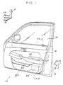
- Fig. 1 is a schematic perspective view illustrating a side door of a vehicle to which the present invention is applied.
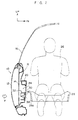
- Fig. 2 is a schematic sectional view taken along a vehicle transverse direction of the side door.
- Fig. 3 is a schematic perspective view illustrating an impact absorbing member to which a first embodiment of the present invention is applied.
- Fig. 4A is a schematic sectional view taken along line 4A-4A of Fig. 3.
- Fig. 4B is a schematic sectional view taken along line 4B-4B of Fig. 3.
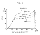
- Fig. 5 is a graph illustrating load-displacement amount curves of impact absorption members to explain the first embodiment.
- Fig. 6 is a graph illustrating a load-displacement amount curve which summarily illustrates ideal variations in the amount of displacement with respect to load at the time of impact absorption.
- Fig. 7 is a perspective view illustrating a schematic structure of an impact absorbing member to which a second embodiment is applied.
- Fig. 8 is a perspective view illustrating a modified example of the impact absorbing member illustrated in Fig. 7.
- Fig. 9A is a graph showing a load-displacement amount curve illustrating experimental results of a sample using the structure of Fig. 7.
- Fig. 9B is a graph showing a load-displacement amount curve illustrating experimental results of a sample using the structure of Fig. 8.
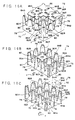
- Fig. 10A is a schematic perspective view illustrating a modified example of an impact absorbing member to which the present invention is applied.
- Fig. 10B is a schematic perspective view illustrating a modified example of an impact absorbing member to which the present invention is applied.
- Fig. 10C is a schematic perspective view illustrating a modified example of an impact absorbing member to which the present invention is applied.
- Figs. 1 and 2 illustrate a vehicle side door 10 to which the present embodiment is applied.
- Figs. 1 and 2 illustrate, as an example, a side door 10 disposed on the right side of a vehicle.
- the arrow UP indicates the upper side in the vertical direction of the vehicle
- the arrow FR indicates the front side in the longitudinal direction of the vehicle
- the arrow IN indicates the inner side in the transverse direction of the vehicle.
- the arrow F represents the direction of force received due to a side collision or the like.
- the side door 10 is an ordinary structure which includes a door outer panel 12, which is formed by a steel plate and provided at the vehicle transverse direction outer side, and a door inner panel 14, which is formed by a steel plate and provided at the vehicle transverse direction inner side.
- a door window glass 16 can be accommodated in the space between the door outer panel 12 and the door inner panel 14.
- a door trim 18 formed from a synthetic resin is provided at the vehicle interior side surface of the door inner panel 14.
- the door pocket 22 is a space formed by a door pocket forming member 22A which is formed from a synthetic resin and mounted to the door inner panel 14 side of the door trim 18.
- An impact absorbing member 24 to which the present invention is applied is disposed at the door inner panel 14 side surface of the door trim 18.
- the impact absorbing member 24 may be resin-molded integrally with the door pocket forming member 22A which is mounted to the door trim 18. In this way, the number of operations involved in assembling the side door 10 can be decreased. In the present first embodiment, only the impact absorbing member 24 is described, and explanation of the connection of the impact absorbing member 24 and the door pocket forming member 22A is omitted.
- the region at which the impact absorbing member 24 is mounted to the door trim 18 opposes a seat frame 28A of a seat 28 on which a vehicle occupant 26 riding in the vehicle is seated. In this way, when an impact load from the vehicle transverse direction outer side is received and the door inner panel 14 moves toward the vehicle inner side, the impact absorbing member 24 is nipped between the door inner panel 14 and the door trim 18.
- Figs. 3, 4A and 4B illustrate the schematic structure of the impact absorbing member 24.
- Any of various synthetic resin materials, such as polypropylene, can be used for the impact absorbing member 24.
- the impact absorbing member 24 has a base plate 30 which curves in accordance with the configuration of the door trim 18.
- An impact absorbing portion 32 is provided integrally with the base plate 30.
- the impact absorbing portion 32 is disposed from the base plate 30 toward the door inner panel 14.
- the base plate 30 is mounted to the door trim 18 by being fixed by any of various methods such as adhesion, welding, screws or the like.
- the base plate 30 may be connected to the door pocket forming member 22A.
- the impact absorbing portion 32 is structured such that, when the impact absorbing member 24 is mounted to the side door 10, a plurality of vertical ribs 34, whose surface direction (i.e, direction along which the surface extends) is along the vertical direction of the vehicle, and a plurality of horizontal ribs 36, whose surface direction is along the horizontal direction of the vehicle, are connected integrally in a lattice-like configuration so as to be disposed at predetermined pitches w 1 (the pitch between the vertical ribs 34) and w 2 (the pitch between the horizontal ribs 36) (see Figs. 4A, 4B).
- vertical ribs 34A through 34G are disposed in a lattice-like configuration between three horizontal ribs 36A through 36C ("horizontal ribs 36" when referred to collectively), such that rectangular column shaped spaces are formed between the vertical ribs 34 and the horizontal ribs 36.
- horizontal ribs 36 By forming the horizontal ribs 36 longer than the vertical ribs 34, the external configuration of the impact absorbing member 24 is a rectangular block shape which is long in the longitudinal direction of the vehicle.
- a predetermined gap is formed between the door inner panel 14 and the impact absorbing portion 32 of the impact absorbing member 24.
- the vertical ribs 34 and the horizontal ribs 36 are disposed such that the ends thereof which are at the door inner panel 14 side are free ends, whereas the ends thereof at the connecting portions which connect the vertical ribs 34 and the horizontal ribs 36 to the base plate 30 are fixed ends.
- the impact absorbing member 24 receives a load, the vertical ribs 34 and the horizontal ribs 36 plastically deform from the door inner panel 14 side (i.e., from the free end side).
- the vertical ribs 34 and the horizontal ribs 36 are respectively formed in a taper shape such that the thickness thereof at the connecting portion for connection with the base plate 30 is thicker than the thickness at the distal end thereof (thickness t 1 of the distal end of the vertical rib 34 or thickness t 2 of the distal end of the horizontal rib 36).
- the cross-sectional area which receives the impact load gradually increases from the free end side toward the base plate 30 side.
- a cut-in portion 40 is provided in the impact absorbing portion 32 of the impact absorbing member 24. Further, an opening 38 is formed in the base plate 30 of the impact absorbing member 24.
- the cut-in portion 40 is a space formed in the impact absorbing portion 32 by cut-out portions 42, each of which is formed by being cut out at the connecting portion of a vertical rib 34 and a horizontal rib 36 in a substantially trapezoidal shape.
- the opening 38 of the base plate 30 is formed so as to pass through the base plate 30 at the portion thereof corresponding to the respective cut-out portions 42. More specifically, each of the cut-out portions 42 is formed so as to straddle the opening 38 of the base plate 30.
- the opening portion 38 having a long-side direction opening width W 1 and a short-side direction opening width W 2 is formed in the substantially central portion of the base plate 30.
- the cut-out portion 42 is provided as cut-out portions 42A through 42D in the respective vertical ribs 34C through 34E and horizontal rib 36B which straddle the opening portion 38.
- the depths of the cut-out portion 42D formed in the horizontal rib 36B straddling the opening portion 38 and the cut-out portion 42B formed in the vertical rib 34D straddling the opening portion 38 reach a position at a length h 2 from the distal end of the horizontal rib 36B, whereas the length of the horizontal rib 36B (as well as the vertical rib 34D) is h 1 . Further, the depths of the cut-out portions 42A, 42C formed in the vertical ribs 34C, 34E, which are adjacent to the vertical rib 34D, reach positions corresponding to the cut-out portion 42D of the horizontal rib 36B.
- reduced cross-sectional area portions 44A through 44D are formed in the vertical ribs 34C through 34E and in the horizontal rib 36B.
- the cross-sectional area of each of the reduced cross-sectional area portions 44A through 44D gradually decreases toward the connecting portion with the base plate 30 from the lengthwise (along the load direction) intermediate portion of the corresponding rib.
- the reduced cross-sectional area portions 44A through 44D are provided so that the total cross-sectional area of the vertical ribs 34 and the horizontal ribs 36 of the impact absorbing member 24 gradually decreases toward the base plate 30 from the lengthwise (i.e., load direction) intermediate portions of the ribs.
- connecting portions 46A through 46C which are the portions at which the vertical ribs 34C through 34E are connected to the horizontal rib 36B respectively, are short.
- the side door 10 When the side door 10 receives an impact load toward the vehicle transverse direction inner side due to a side collision or the like, the side door outer panel 12 and the side door inner panel 14 are pushed inwardly in the vehicle transverse direction.
- the impact energy is absorbed due to the plastic deformation (e.g., buckling or the like) of the distal ends of the vertical ribs 34 and the horizontal ribs 36 which abut the door inner panel 14.
- the cross-sectional area which receives the load increases, it becomes difficult for plastic deformation to occur, and the load received by the base plate 30 is large.
- the reduced cross-sectional area portions 42A through 42D are provided at the base plate 30 side of the vertical ribs 34C through 34E and the horizontal rib 36B. Therefore, the load-receiving cross-sectional areas of the vertical ribs 34C through 34E and the horizontal rib 36B at the portions thereof from the lengthwise (along the load direction) intermediate portion toward the base plate 30 are reduced so that these portions plastically deform easily. The load received due to the impact energy can thereby be prevented from becoming high.
- the withstand load characteristic can easily be changed to a withstand load characteristic of a desired load energy absorbing amount.
- Fig. 5 illustrates load-displacement amount curves for sample 1 and sample 2, which are impact absorbing members 24 in which the cut-in portion 40 is provided, and sample 3, which is an impact absorbing member in which no cut-in portion 40 is formed.
- the interval pitch w 1 between the vertical ribs 34 is 35 mm
- the interval pitch w 2 between the horizontal ribs 36 is 50 mm
- the rib height h 1 is 70 mm
- the base plate 30 is provided with a gentle incline.
- the thickness t 1 of the distal ends of the vertical ribs 34 and the thickness t 2 of the distal ends of the horizontal ribs 36 are 0.8 mm.
- the samples 1 through 3 are injection molded to the same external configuration by using Sumitomo Noburene WP712F mentioned previously. Further, as mentioned previously, the opening portion 38 and the cut-in portion 40 are not formed in sample 3.
- the cross-sectional area gradually increases from the distal end of the impact absorbing member toward the base plate.
- the cut-out portions 42B, 42D are formed in the vertical rib 34D and the horizontal rib 36B.
- the opening 38 is formed larger than that of sample 2. Therefore, in sample 1, the amount of the reduction of the cross-sectional area of the impact absorbing portion 32 is greater than that of sample 2.
- the load F increases in accordance with the amount of displacement S.
- the load F is substantially constant in a state in which the amount of displacement S is lower than in sample 2.
- the value of the load F at this time is also lower than in sample 2.
- the load F is controlled to a substantially constant value, and variations which are extremely near to the ideal load-displacement amount curve are exhibited. It can therefore be understood that, by varying the size of the cut-in portion 40, the load-displacement amount curve and the load F can be controlled.
- impact absorbing members such as sample 3 in which an opening 38 and a cut-in portion 40 are not formed, or impact absorbing members 24 in which a small opening 38 and a small cut-in portion 40 are formed are provisionally molded.
- the vertical ribs 34 and the horizontal ribs 36 are cut-in bit-by-bit so as to form the cut-in portion 40, and the opening 38 of the base plate 30 is made larger to match the cut-in portion 40.
- the size of the cut-in portion 40 and the size of the opening 38 are determined such that the load-displacement amount curve and the load values become desired values.
- an impact absorbing member 24 having the desired withstand load characteristic can be manufactured.
- a mold for injection molding an impact absorbing member 24 having a desired withstand load characteristic is formed by changing the mold used initially and provisionally to a cut-in portion 40 and an opening 38 which provide an optimum withstand load characteristic.
- the interval pitches w 1 , w 2 and the like of the vertical ribs 34 and the horizontal ribs 36 there is no need to drastically remake the mold. Therefore, the period of time from the trial manufacturing stage of the impact absorbing member 24 to the mass production stage can be shortened, the work involved therein can be facilitated, and the manufacturing cost can be kept down.
- the impact absorbing member 24 because the opening 38 is formed in the base plate 30 in accordance with the cut-in portion 40 of the impact absorbing portion 32, the impact absorbing member 24 can very easily be removed from the mold even if the cut-out portions 42 are provided in the base plate 30 sides of the vertical ribs 34 and the horizontal ribs 36.
- Fig. 7 illustrates a schematic structure of an impact absorbing member 50 to which the second embodiment is applied
- Fig. 8 illustrates a schematic structure of an impact absorbing member 52 to which the second embodiment is applied.
- description of structures at times when the impact absorbing members 50, 52 are actually formed at side doors 10 of vehicles are omitted, and explanation is given of the impact absorbing members 50, 52 formed experimentally.
- the impact absorbing member 50 is provided with an impact absorbing portion 60 which is formed in a lattice shape by ribs 56A through 56C ("ribs 56" when referred to collectively), which are disposed parallel to one another at interval pitches of w 3 at a square, flat-plate shaped base plate 54, and ribs 58A through 58D ("ribs 58" when referred to collectively), which intersect the ribs 56A through 56C and are disposed parallel to one another at interval pitches of w 4 .
- the impact absorbing portion 60 is enclosed on three sides by the rib 56A and the ribs 58A, 58D.
- the ribs 56A, 58A, 58D are provided so as to project higher, by a height h 3 , than the ribs 56B, 56C, 58B, 58C which are enclosed by the ribs 56A, 58A, 58D.
- the ribs 56A, 58A, 58D are formed integrally with the base plate 54.
- Cut-out portions 62A, 62B are formed in the base plate 54 sides of the ribs 56A, 58A, 58D enclosing the periphery of the impact absorbing portion 60.
- the cut-out portion 62A formed in the rib 56A is formed between, on the one hand, the joined portion of the rib 56A and the rib 58B, and on the other hand, the joined portion of the rib 56A and the rib 58C.
- a cut-out portion 62B is formed between, on the one hand, the joined portion of the rib 56A and the rib 58A, and on the other hand, the joined portion of the rib 56A and the rib 58B.
- Another cut-out portion 62B is formed between, on the one hand, the joined portion between the rib 56A and the rib 58D, and on the other hand, the joined portion of the rib 56A and the rib 58C.
- Reduced cross-sectional area portions 64A are formed in the rib 56A in a vicinity of the base plate 54 by the cut-out portions 62A, 62B.
- cut-out portions 62A are formed in the ribs 58A and 58D between the joined portions with the rib 56B and the joined portions with the rib 56C.
- the cut-out portions 62B are formed between, on the one hand, the joined portions of the rib 56A with the rib 58A and the rib 58D, and on the other hand, the joined portions of the rib 56B with the rib 58A and the rib 58D.
- Reduced cross-sectional area portions 64B are formed in the rib 58A and the rib 58D in a vicinity of the base plate 54 by the cut-out portions 62A, 62B.
- the cut-out portion 62B of the rib 58D is omitted from Fig. 7.
- the impact absorbing member 52 has an impact absorbing portion 66 in which a rib 56D is added to the impact absorbing portion 60 of the previously-described impact absorbing member 50.
- the periphery of the impact absorbing portion 66 is therefore surrounded by the ribs 56A, 56D, 58A, 58D.
- Fig. 8 illustrates the impact absorbing member 52 as seen from a different direction than the impact absorbing member 50 illustrated in Fig. 7.
- the cut-out portions 62A, 62B are formed in the rib 56D of the impact absorbing member 52.
- the reduced cross-sectional area portions 64A are formed in the rib 56D in a vicinity the base plate 54 by the cut-out portions 62A, 62B.
- reduced cross-sectional area portions 64C are formed in the base plate 54 sides of the ribs 58A, 58D. (In the same way as in Fig. 7, the reduced cross-sectional area portions 64C of the rib 58D are omitted from Fig. 8.)
- Fig. 9A illustrates a load-displacement amount curve obtained by experimentation by using the impact absorbing member 50 as sample 4.
- Fig. 9B illustrates a load-displacement amount curve using the impact absorbing member 52 as sample 5.
- the peripheries are 90 mm ⁇ 90 mm and the heights h 4 are 80 mm, such that the external configuration dimensions are the same.
- the interval pitches w 3 , w 4 of the ribs 56, 58 respectively are 30 mm.
- the height difference h 3 between the peripheral ribs 56A, (56D), 58A, 58D and the central portion ribs 56B, 56C, 58B, 58C is 5 mm.
- the widthwise dimension w 5 of the upper edge of each of the cut-out portions 62A, 62B (i.e., the end portion at the side opposite the base plate 54) is 5 mm.
- the interval w 6 , at the base plate 54 side, between adjacent cut-out portions 62A, 62B is 10 mm in samples 4 and 5.
- the height h 5 from the distal ends of the ribs 56A, 58A, 58D to the cut-out portions 62A, 62B is 35 mm, and in sample 5, the height h 5 is 20 mm. Further, experimental measurement was carried out by colliding a collision body of 20 kgF at a speed of 4.5 m/s.
- both sample 4 and sample 5 exhibit a substantially ideal load-displacement amount curve.
- the dashed line in Figs. 9A and 9B represents the ideal curve.
- Samples 4 and 5 differ with respect to the existence of the rib 56D. However, by varying the sizes of the cut-out portions 62A, 62B, i.e., by varying the reduced cross-sectional area portions 64A through 64C, a load-displacement amount curve which is near to the ideal can be obtained for both sample 4 and sample 5. More specifically, the difference in the numbers of the ribs 56, 58 can be compensated for by adjusting the reduced cross-sectional area portions 64A through 64C.
- reduced cross-sectional area portions 64A through 64C may be provided at the peripheral ribs 56A, 56D, 58A, 58D in order to control the withstand load characteristic.
- the impact absorbing members 24, 50, 52 to which the first and second embodiments are applied are not intended to limit the structure of the impact energy absorbing member of the present invention.
- cut-out portions 62A, 62B are formed in the ribs 56A, 56D, 58A, 58B in the second embodiment, cut-out portions having respectively different sizes may be provided.
- first and second embodiments described examples in which a plurality of ribs are arranged in a lattice configuration.
- the respective ribs may be formed along the load direction.
- the ribs may be formed in any of various configurations such as a honeycomb shape, a pentagon shape, or the like.
- the vertical ribs 34 and the horizontal ribs 36 are formed integrally with the base plate 30 of the impact absorbing member 24, and the opening 38 is provided in the base plate 30.
- the ribs 56, 58 are formed integrally with the base plate 54.
- the configurations and the existence of the base plates 30, 54, and the size and the configuration of the opening 38 formed in the base plate 30 are not limited to those described in the first and second embodiments. Other embodiments will be described hereinafter by using Figs. 10A, 10B and 10C.
- Figs. 10A, 10B and 10C illustrate impact absorbing members 72, 74, 76, respectively, which are all provided with an impact absorbing portion 70 having the same structure.
- the impact absorbing portion 70 used in the impact absorbing members 72, 74, 76 has a lattice shape formed by a plurality of ribs 78, 80.
- Reduced cross-sectional area portions 84A are formed in the ribs 78 by cut-out portions 82A formed between the plurality of joined portions of the ribs 78 and the ribs 80.
- reduced cross-sectional area portions 84B are formed in the ribs 80 by cut-out portions 82B formed between the plurality of joined portions of the ribs 80 and the ribs 78.
- the impact absorbing portion 70 and a base plate 86 are formed integrally. Openings 88A, 88B are formed in the base plate 86 at positions opposing the cut-out portions 82A, 82B provided in the ribs 78, 80.
- the openings formed in the base plate in the present embodiment pass through the base plate and expose the cut-out portions formed in the ribs. In this way, the structure of the mold used for injection molding is simplified, and removal of the impact absorbing member from the mold after injection molding is facilitated.
- a small base plate 90 is formed integrally with a plurality of the ribs 78, 80 so as to span between the plurality of the ribs 78, 80 at the impact absorbing portion 70.
- the impact absorbing member 74 can be fixed to a predetermined position of the door trim 18 by using this small base plate 90.
- the impact absorbing member 76 is formed only by the impact absorbing portion 70.
- the cut-out portion 82A, 82B side of the impact absorbing portion 70 i.e., the distal end portion side of the reduced cross-sectional area portions 84A, 84B
- the cut-out portion 82A, 82B side of the impact absorbing portion 70 can be made to abut and mounted to a predetermined region of the door trim 18 or the like so as to become the fixed ends.
- the plastic deformation of the ribs 78, 80 begins from the opposite side of the fixed ends (the opposite side of the cut-out portions 82A, 82B) when an impact load is received.
- a through hole 90A may be provided in the small base plate 90 of the impact absorbing member 74, so that the impact absorbing member 74 may be fixed to the door trim 18 by a clip or a screw or the like inserted in the through hole 90A. Further, a flange 92 or the like for mounting to the door trim or the like may be formed at the impact absorbing member 76. The through hole 90A may be formed in the flange 92.
- the existence of a base plate formed integrally with the ribs and the size of a base plate can be set arbitrarily, and the desired withstand load characteristic can be obtained by the cut-out portions formed in the ribs.
- the impact energy absorbing members of the present invention are formed integrally with the door pocket forming member 22A and mounted to the door trim 18.
- the present invention is not limited to the same, and, for example, the impact energy absorbing members may be mounted to the door inner panel 14 or the like.
- a cut-out portion may be formed in the door inner panel 14, and plastic deformation may start from the free end side of the door trim 18 side when an impact load is received. More specifically, one end in the impact load direction may be the fixed end, and plastic deformation may start from the free end opposite to this fixed end. In this way, the reduced cross-sectional area portions can control the withstand load characteristic.
- the cut-out portions are provided in the thick sides of the ribs which are formed in taper shapes.
- the configuration of the ribs is not limited to this shape, and, for example, the ribs may be straight so as to have a uniform thickness along the load direction.
- the impact energy absorbing member has: a plurality of ribs whose respective surface directions are provided substantially along an impact load direction, respective ones of ends of the plurality of ribs in the surface directions of the plurality of ribs being fixed to predetermined positions within the vehicle door; and reduced cross-sectional area portions provided at fixed end sides of the plurality of ribs at which fixed end sides the ones of ends of the plurality of ribs are fixed, the reduced cross-sectional area portions being provided such that cross-sectional areas of the plurality of ribs along a direction orthogonal to the impact load direction become smaller toward the fixed end sides of the plurality of ribs from lengthwise intermediate portions of the plurality of ribs whose lengths run along the impact load direction.
Landscapes
- Engineering & Computer Science (AREA)
- Mechanical Engineering (AREA)
- Vibration Dampers (AREA)
Description
- The present invention relates to an impact energy absorbing member according to the preamble of
claim 1, which is provided at the interior portion of an automobile door and absorbs impact energy at the time of a side collision. In particular, the present invention relates to an impact energy absorbing member in which, when the impact energy absorbing member receives an impact load, resin ribs plastically deform so as to absorb the impact energy. - A structure has conventionally been known in which an energy absorbing member is provided in the side door of a vehicle such as an automobile for times when the side door receives an impact load from the vehicle transverse direction due to a side collision or the like. For example, JP-U-5-410, 3-13251, JP-U-3-49110 and JP-U-3-49111 disclose methods of absorbing the impact due to load at the time of a side collision by disposing an impact absorbing member formed from foamed urethane, foamed styrene or the like within a side door separately from the parts of the door.
- JP-U-4-128912, JP-A-6-72153, JP-U-6-78035, JP-A-6-247199, and JP-U-7-31432 disclose various impact absorbing members which absorb impacts by resin members which are formed by a plurality of ribs. Further, JP-U-7-13533 discloses an impact absorbing body having a hollow, box-shaped structural body which is mounted to the inner side of the door trim with an opening thereof oriented toward the door inner panel. The side wall portions of this structural body are inclined with respect to the direction in which the opening opens. JP-A-7-52735 discloses forming hollow bosses at the points of intersection of lattice-shaped ribs provided at the reverse surface of the door trim. In JP-A-7-228144, lattice-shaped resin ribs, in which slits for adjusting compression/buckling are formed at ones of sides or both sides of the ribs, are provided at the reverse surface of a door trim base plate. JP-A-7-232556 discloses providing a gap between the inner panel and the distal ends of ribs which extend perpendicularly from the door trim, and forming cut-out portions in the centers of the rib distal ends. In this way, impact absorption is carried out in two stages.
- These impact absorbing members absorb impact energy due to the plastic deformation of ribs which receive load due to the impact. By molding the impact absorbing members from resin, the ribs can be molded integrally with, for example, the door pocket provided at the side door, so that the number of processes for assembling the side door can be decreased.
- Fig. 6 illustrates an ideal load-displacement amount curve (withstand load characteristic) of an impact absorbing member at the time of impact energy absorption. In an impact absorbing member having an ideal withstand load characteristic, immediately after the impact absorbing member receives the impact load and begins to deform plastically, the load increases in accordance with the amount of displacement. However, when the load reaches a predetermined value and thereafter, variations in the load are suppressed, and only the amount of displacement changes. The energy absorption amount of the impact absorbing member is expressed by the area between the load-displacement amount curve and the horizontal axis. The closer the configuration of the region between the load-displacement amount curve and the horizontal axis is to a rectangle, the greater the area of this region. The ideal withstand load characteristic is substantially constant, without a sudden increase in the load, and has a low load value.
- The withstand load characteristic needed for the impact absorbing member differs in accordance with the conditions of usage, the structure of the side door, the parts which are used, and the like. It is known that, when ribs are used as impact absorbing members, the withstand load characteristic varies greatly in accordance with the thickness of the ribs, the size of the ribs, and the intervals (pitches) at which the ribs are disposed. In particular, when the ribs are formed by injection molding or the like, drafts must be formed at the ribs in order to remove the molded product from the mold. Accordingly, the ribs are formed in taper shapes with the distal ends thereof being thin, and the proximal base portions thereof being thick. Although it is easy for the distal ends of such ribs to deform plastically, it is difficult for the proximal base portions thereof to deform plastically.
- Therefore, when the impact absorbing member is being manufactured, in order to obtain a desired withstand load characteristic, the thickness of the ribs, the size of the ribs, the intervals (pitches) at which the ribs are disposed and the like are determined. A mold is made in accordance with the determined dimensions, and resin molding is carried out.
- However, in a case in which the desired withstand load characteristic is not obtained, it is necessary to change the thickness of the ribs, the size of the ribs, the pitches, or the like. Because such changes affect the configuration of the mold to be used for molding, it is necessary to manufacture a new mold. Through such a process, manufacturing an impact absorbing member which results in a desired withstand load characteristic is extremely difficult work. The costs involved in manufacturing the impact absorbing member increase, and a long period of time for production is required from the trial manufacturing stage until the mass production stage.
- The above-mentioned JP-A-6-247199 (preamble of claim 1) shows a generic impact energy absorbing member provided within a vehicle door. Due to impact load from an exterior, the impact energy absorbing member plastically deforms so as to absorb impact energy. A plurality of ribs are provided whose respective surfaces are provided substantially along an impact load direction defining a lengthwise direction thereof. Respective ones of ends of the plurality of ribs along the impact load direction are fixed to a door trim of the vehicle door. The plurality of ribs comprises reduced cross-sectional area portions which are provided such that cross-sectional areas of the plurality of ribs along a direction orthogonal to the impact load direction are smaller than the cross-sectional areas at lengthwise intermediate portions of the plurality of ribs.
- It is an object of the present invention to further develop an impact energy absorbing member according to the preamble of
claim 1 such that a desired load characteristic can easily be obtained. - According to the invention, this object is achieved by an impact energy absorbing member having the features of
claim 1. - Advantageous further developments are set out in the dependent claims.
- In accordance with the invention, when an impact load is received, plastic deformation of the ribs begins from the side opposite to the fixed ends, and the impact energy is absorbed. The reduced cross-sectional area portions make the cross-sectional area receiving the load at the fixed end sides of the ribs smaller. As a result, when plastic deformation of the ribs receiving the impact load proceeds toward the fixed end sides of the ribs and reaches the reduced cross-sectional area portions, because the cross-sectional area receiving the load is reduced, the plastic deformation of the ribs proceeds without the deformation load becoming remarkably large. Impact energy can thereby be reliably absorbed at a low load.
- The reduced cross-sectional area portions provided at the fixed end sides of the ribs are formed by cut-out portions in the fixed ends of the ribs. By changing the cross-sectional areas of the reduced cross-sectional area portions, the rate of plastic deformation of the ribs with respect to the impact load can be changed. As a result, by adjusting the cut-out amount at the time of forming the cut-out portions in the fixed end sides of the ribs, the rate of absorption of impact energy by the ribs can be adjusted, which is easier than changing the rib thickness or the intervals between ribs or the like in order to obtain a desired withstand load characteristic. The cut-out portions in this case may be formed, after the ribs are manufactured, by a method of cutting out sections of the ribs or the like. Or, during molding of the ribs, portions of the ribs other than the cut-out portions may be molded so as to substantially form the cut-out portions. These methods of forming the cut-out portions may be applied to all embodiments of the present invention.
- The fixed ends of the ribs are at the side at which ones of ends of the ribs along the impact load direction are fixed and at which it is hard for plastic deformation (buckling) to occur immediately after the ribs have received the impact load. The other-end portions of the ribs are free ends. When an impact load is received, the ribs may start to plastically deform from the free end sides thereof.
- Preferably, the plurality of ribs are formed in taper shapes such that thicknesses of the ones of ends of the plurality of ribs provided at the fixed end sides of the plurality of ribs are greater than thicknesses of the other ends of the plurality of ribs.
- In accordance with this advantageous further development, by forming the ribs in taper shapes, the impact energy absorbing member can easily be removed from a mold when injection molding is carried out. Here, although the fixed end sides of the ribs are thick, by providing the reduced cross-sectional area portions by cutting out sections of these thick portions of the ribs or the like, the ribs can easily plastically deform even at the thick portions thereof.
- With ribs formed in taper shapes in particular, plastic deformation proceeds from the free end sides, and the load gradually becomes large. However, by providing the reduced cross-sectional area portions at the fixed end sides, the deformation load of the ribs at the fixed end sides can be decreased, and the efficiency of absorbing the impact energy can be improved.
- Preferably, the fixed ends of the plurality of ribs along the impact load direction are connected to a base plate portion. The base plate portion can be used for connection at the time the ribs are molded integrally with a part within the vehicle door.
- In ribs which receive impact load, plastic deformation is generated from the free ends at the opposite side of the base plate portion. The reduced cross-sectional area portions plastically deform in accordance with the progression of the plastic deformation of the ribs. However, by adjusting the reduced cross-sectional areas at the reduced cross-sectional area portions, the withstand load characteristic can be adjusted.
- Further preferably, the base plate portion has an opening which passes through the base plate portion and communicates with the cut-out portions formed in the plurality of ribs.
- In accordance with this advantageous further development, the cut-out portions are provided at the base plate portion sides of the ribs, and an opening is formed in the base plate portion so as to correspond to the cut-out portions. If the cut-out portions are provided in the base plate portion sides of the ribs, it is difficult to remove the impact energy absorbing member from the mold at the time of molding. However, by providing the opening which passes through the base plate portion, the manufacturing of the mold for carrying out injection molding and the removal of the molded product from the mold are simplified, and the molding work becomes extremely easy.
- As described above, a desired withstand load characteristic is obtained by providing the reduced cross-sectional area portions at the fixed end sides of the ribs and varying the reduced cross-sectional area portions. Further, even if the ribs are formed in taper shapes, plastic deformation proceeds surely, and the impact energy can be absorbed efficiently.
- By forming the ribs and the base plate portion integrally, the mounting of the impact energy absorbing member to the interior of the vehicle door is facilitated, and impact energy can be absorbed efficiently by the reduced cross-sectional area portions.
- Because the opening is provided in the base plate portion, excellent effects are achieved in that the injection molding operation is made extremely easy by providing the reduced cross-sectional area portions, the manufacturing cost can be kept down, and the period of time of work from the trial manufacturing stage to the mass production stage can be shortened.
- Fig. 1 is a schematic perspective view illustrating a side door of a vehicle to which the present invention is applied.
- Fig. 2 is a schematic sectional view taken along a vehicle transverse direction of the side door.
- Fig. 3 is a schematic perspective view illustrating an impact absorbing member to which a first embodiment of the present invention is applied.
- Fig. 4A is a schematic sectional view taken along
line 4A-4A of Fig. 3. - Fig. 4B is a schematic sectional view taken along
line 4B-4B of Fig. 3. - Fig. 5 is a graph illustrating load-displacement amount curves of impact absorption members to explain the first embodiment.
- Fig. 6 is a graph illustrating a load-displacement amount curve which summarily illustrates ideal variations in the amount of displacement with respect to load at the time of impact absorption.
- Fig. 7 is a perspective view illustrating a schematic structure of an impact absorbing member to which a second embodiment is applied.
- Fig. 8 is a perspective view illustrating a modified example of the impact absorbing member illustrated in Fig. 7.
- Fig. 9A is a graph showing a load-displacement amount curve illustrating experimental results of a sample using the structure of Fig. 7.
- Fig. 9B is a graph showing a load-displacement amount curve illustrating experimental results of a sample using the structure of Fig. 8.
- Fig. 10A is a schematic perspective view illustrating a modified example of an impact absorbing member to which the present invention is applied.
- Fig. 10B is a schematic perspective view illustrating a modified example of an impact absorbing member to which the present invention is applied.
- Fig. 10C is a schematic perspective view illustrating a modified example of an impact absorbing member to which the present invention is applied.
- A first preferred embodiment of the present invention will be described hereinafter with reference to the drawings. Figs. 1 and 2 illustrate a
vehicle side door 10 to which the present embodiment is applied. Figs. 1 and 2 illustrate, as an example, aside door 10 disposed on the right side of a vehicle. In the figures, the arrow UP indicates the upper side in the vertical direction of the vehicle, the arrow FR indicates the front side in the longitudinal direction of the vehicle, and the arrow IN indicates the inner side in the transverse direction of the vehicle. The arrow F represents the direction of force received due to a side collision or the like. - The
side door 10 is an ordinary structure which includes a doorouter panel 12, which is formed by a steel plate and provided at the vehicle transverse direction outer side, and a doorinner panel 14, which is formed by a steel plate and provided at the vehicle transverse direction inner side. Adoor window glass 16 can be accommodated in the space between the doorouter panel 12 and the doorinner panel 14. - A door trim 18 formed from a synthetic resin is provided at the vehicle interior side surface of the door
inner panel 14. Anarm rest 20, which projects toward the vehicle interior, and adoor pocket 22, which projects toward the vehicle interior and is open, are provided at thedoor trim 18. Thedoor pocket 22 is a space formed by a doorpocket forming member 22A which is formed from a synthetic resin and mounted to the doorinner panel 14 side of thedoor trim 18. - An
impact absorbing member 24 to which the present invention is applied is disposed at the doorinner panel 14 side surface of thedoor trim 18. Theimpact absorbing member 24 may be resin-molded integrally with the doorpocket forming member 22A which is mounted to thedoor trim 18. In this way, the number of operations involved in assembling theside door 10 can be decreased. In the present first embodiment, only theimpact absorbing member 24 is described, and explanation of the connection of theimpact absorbing member 24 and the doorpocket forming member 22A is omitted. - As illustrated in Fig. 2, the region at which the
impact absorbing member 24 is mounted to the door trim 18 opposes aseat frame 28A of aseat 28 on which avehicle occupant 26 riding in the vehicle is seated. In this way, when an impact load from the vehicle transverse direction outer side is received and the doorinner panel 14 moves toward the vehicle inner side, theimpact absorbing member 24 is nipped between the doorinner panel 14 and thedoor trim 18. - Figs. 3, 4A and 4B illustrate the schematic structure of the
impact absorbing member 24. Any of various synthetic resin materials, such as polypropylene, can be used for theimpact absorbing member 24. Theimpact absorbing member 24 of the present embodiment is injection molded by using the following product (commercial name) from Sumitomo Chemical Co., Ltd.: Sumitomo Nobulene WP712F (ethylene-propylene block copolymer, melt flow rate (MFR) = 15). - As illustrated in Fig. 3, the
impact absorbing member 24 has abase plate 30 which curves in accordance with the configuration of thedoor trim 18. Animpact absorbing portion 32 is provided integrally with thebase plate 30. Theimpact absorbing portion 32 is disposed from thebase plate 30 toward the doorinner panel 14. Thebase plate 30 is mounted to the door trim 18 by being fixed by any of various methods such as adhesion, welding, screws or the like. When theimpact absorbing member 24 is molded integrally with the doorpocket forming member 22A, thebase plate 30 may be connected to the doorpocket forming member 22A. - The
impact absorbing portion 32 is structured such that, when theimpact absorbing member 24 is mounted to theside door 10, a plurality ofvertical ribs 34, whose surface direction (i.e, direction along which the surface extends) is along the vertical direction of the vehicle, and a plurality ofhorizontal ribs 36, whose surface direction is along the horizontal direction of the vehicle, are connected integrally in a lattice-like configuration so as to be disposed at predetermined pitches w1 (the pitch between the vertical ribs 34) and w2 (the pitch between the horizontal ribs 36) (see Figs. 4A, 4B). In the present embodiment, as an example, sevenvertical ribs 34A through 34G ("vertical ribs 34" when referred to collectively) are disposed in a lattice-like configuration between threehorizontal ribs 36A through 36C ("horizontal ribs 36" when referred to collectively), such that rectangular column shaped spaces are formed between thevertical ribs 34 and thehorizontal ribs 36. By forming thehorizontal ribs 36 longer than thevertical ribs 34, the external configuration of theimpact absorbing member 24 is a rectangular block shape which is long in the longitudinal direction of the vehicle. - As illustrated in Fig. 2, a predetermined gap is formed between the door
inner panel 14 and theimpact absorbing portion 32 of theimpact absorbing member 24. In this way, thevertical ribs 34 and thehorizontal ribs 36 are disposed such that the ends thereof which are at the doorinner panel 14 side are free ends, whereas the ends thereof at the connecting portions which connect thevertical ribs 34 and thehorizontal ribs 36 to thebase plate 30 are fixed ends. When theimpact absorbing member 24 receives a load, thevertical ribs 34 and thehorizontal ribs 36 plastically deform from the doorinner panel 14 side (i.e., from the free end side). - As illustrated in Figs. 4A and 4B, in order to easily remove the
impact absorbing member 24 from a mold after molding, thevertical ribs 34 and thehorizontal ribs 36 are respectively formed in a taper shape such that the thickness thereof at the connecting portion for connection with thebase plate 30 is thicker than the thickness at the distal end thereof (thickness t1 of the distal end of thevertical rib 34 or thickness t2 of the distal end of the horizontal rib 36). In this way, for each of thevertical ribs 34 and thehorizontal ribs 36, the cross-sectional area which receives the impact load (the cross-sectional area when cutting in a direction orthogonal to the vehicle transverse direction) gradually increases from the free end side toward thebase plate 30 side. - As shown in Fig. 3, a cut-in
portion 40 is provided in theimpact absorbing portion 32 of theimpact absorbing member 24. Further, anopening 38 is formed in thebase plate 30 of theimpact absorbing member 24. - The cut-in
portion 40 is a space formed in theimpact absorbing portion 32 by cut-outportions 42, each of which is formed by being cut out at the connecting portion of avertical rib 34 and ahorizontal rib 36 in a substantially trapezoidal shape. Theopening 38 of thebase plate 30 is formed so as to pass through thebase plate 30 at the portion thereof corresponding to the respective cut-outportions 42. More specifically, each of the cut-outportions 42 is formed so as to straddle theopening 38 of thebase plate 30. - As shown in Figs. 4A and 4B, in the first embodiment, as one example, the opening
portion 38 having a long-side direction opening width W1 and a short-side direction opening width W2 is formed in the substantially central portion of thebase plate 30. The cut-outportion 42 is provided as cut-outportions 42A through 42D in the respectivevertical ribs 34C through 34E andhorizontal rib 36B which straddle theopening portion 38. - The depths of the cut-out
portion 42D formed in thehorizontal rib 36B straddling the openingportion 38 and the cut-outportion 42B formed in thevertical rib 34D straddling the openingportion 38 reach a position at a length h2 from the distal end of thehorizontal rib 36B, whereas the length of thehorizontal rib 36B (as well as thevertical rib 34D) is h1. Further, the depths of the cut-outportions vertical ribs vertical rib 34D, reach positions corresponding to the cut-outportion 42D of thehorizontal rib 36B. - In this way, reduced cross-sectional area portions 44A through 44D are formed in the
vertical ribs 34C through 34E and in thehorizontal rib 36B. The cross-sectional area of each of the reduced cross-sectional area portions 44A through 44D gradually decreases toward the connecting portion with thebase plate 30 from the lengthwise (along the load direction) intermediate portion of the corresponding rib. The reduced cross-sectional area portions 44A through 44D are provided so that the total cross-sectional area of thevertical ribs 34 and thehorizontal ribs 36 of theimpact absorbing member 24 gradually decreases toward thebase plate 30 from the lengthwise (i.e., load direction) intermediate portions of the ribs. Further, due to the cut-outportions 42A through 42D, the length, along the load direction, of connectingportions 46A through 46C, which are the portions at which thevertical ribs 34C through 34E are connected to thehorizontal rib 36B respectively, are short. When theimpact absorbing portion 32 receives an impact load, it is easy for theimpact absorbing portion 32 to break at the connectingportions 46A through 46C. - Next, operation of the first embodiment will be described.
- When the
side door 10 receives an impact load toward the vehicle transverse direction inner side due to a side collision or the like, the side doorouter panel 12 and the side doorinner panel 14 are pushed inwardly in the vehicle transverse direction. The doorinner panel 14, which is moved toward the interior of the vehicle due to the impact load, abuts theimpact absorbing member 24 mounted to thedoor trim 18. Impact load is thereby applied to theimpact absorbing member 24. - When impact load is applied to the
impact absorbing member 24, first, the impact energy is absorbed due to the plastic deformation (e.g., buckling or the like) of the distal ends of thevertical ribs 34 and thehorizontal ribs 36 which abut the doorinner panel 14. - When the cross-sectional area which receives the load increases, it becomes difficult for plastic deformation to occur, and the load received by the
base plate 30 is large. However, in theimpact absorbing member 24, the reducedcross-sectional area portions 42A through 42D are provided at thebase plate 30 side of thevertical ribs 34C through 34E and thehorizontal rib 36B. Therefore, the load-receiving cross-sectional areas of thevertical ribs 34C through 34E and thehorizontal rib 36B at the portions thereof from the lengthwise (along the load direction) intermediate portion toward thebase plate 30 are reduced so that these portions plastically deform easily. The load received due to the impact energy can thereby be prevented from becoming high. - More specifically, at the
impact absorbing member 24, plastic deformation proceeds easily to a vicinity of thebase plate 30 in accordance with the magnitude of the load, so that the impact energy can reliably be absorbed. Accordingly, the load received by thebase plate 30 of theimpact absorbing member 24 does not become large. - In the above-described
impact absorbing member 24, by varying the size of the cut-inportion 40, i.e., by varying the position at which the cross-sectional area of theimpact absorbing portion 32 decreases and the amount of decrease in the cross-sectional area, the withstand load characteristic can easily be changed to a withstand load characteristic of a desired load energy absorbing amount. - Fig. 5 illustrates load-displacement amount curves for
sample 1 andsample 2, which areimpact absorbing members 24 in which the cut-inportion 40 is provided, andsample 3, which is an impact absorbing member in which no cut-inportion 40 is formed. - In each of
sample vertical ribs 34 is 35 mm, the interval pitch w2 between thehorizontal ribs 36 is 50 mm, the rib height h1 is 70 mm, and thebase plate 30 is provided with a gentle incline. Further, in thesamples 1 through 3, the thickness t1 of the distal ends of thevertical ribs 34 and the thickness t2 of the distal ends of thehorizontal ribs 36 are 0.8 mm. Thesamples 1 through 3 are injection molded to the same external configuration by using Sumitomo Noburene WP712F mentioned previously. Further, as mentioned previously, the openingportion 38 and the cut-inportion 40 are not formed insample 3. By forming thevertical ribs 34 and thehorizontal ribs 36 respectively in taper shapes insample 3, the cross-sectional area gradually increases from the distal end of the impact absorbing member toward the base plate. - In
sample 2, the opening widths W1, W2 of theopening 38 formed in thebase plate 30 are W1 = 70 mm and W2 = 20 mm. The length h2 from the distal end of the rib to the cut-inportion 40 is h2 = 20 mm. The cut-outportions vertical rib 34D and thehorizontal rib 36B. - In
sample 1, the opening widths W1, W2 are W1 = 120 mm and W2 = 20 mm. The length h2 from the distal end of the rib to the cut-inportion 40 is h2 = 20 mm. Theopening 38 is formed larger than that ofsample 2. Therefore, insample 1, the amount of the reduction of the cross-sectional area of theimpact absorbing portion 32 is greater than that ofsample 2. - Experimental measurements were conducted by colliding a 20.0 kgF collision body against each of
samples 1 through 3 at a speed of 5.90 m/s. The amount of movement of the collision body from immediately after collision was measured as amount of displacement S (mm), and the load F (kN) received by thebase plate 30 in accordance with the amount of movement S was measured. - As illustrated in Fig. 5, in the
sample 3 in which neither theopening 38 nor the cut-inportion 40 were formed, the load F increased as the deformation progressed, such that a curve which was not near to the ideal curve illustrated in Fig. 6 was obtained. - In contrast, in
sample 2, in the initial stages of collision of the collision body, the load F becomes high in accordance with the amount of displacement S. However, when the amount of displacement S increases to a certain extent, a region in which the load F is substantially constant regardless of the increase in the amount of displacement S arises. In this way, with thesample 2 in which the cut-inportion 40 is formed, the increase in the load F corresponding to the amount of displacement S is suppressed and the highest value of the load F is also held down, as compared withsample 3 in which no cut-inportion 40 is formed. It can therefore be understood that, as compared withsample 3,sample 2 is rather near to the ideal load-displacement amount curve (see Fig. 6). - With
sample 1, in which the cut-inportion 40 is made larger than that ofsample 2, immediately after the collision body collides, the load F increases in accordance with the amount of displacement S. However, the load F is substantially constant in a state in which the amount of displacement S is lower than insample 2. The value of the load F at this time is also lower than insample 2. Further, withsample 1, even if the amount of displacement S increases, the load F is controlled to a substantially constant value, and variations which are extremely near to the ideal load-displacement amount curve are exhibited. It can therefore be understood that, by varying the size of the cut-inportion 40, the load-displacement amount curve and the load F can be controlled. - For example, when the
impact absorbing member 24 is being developed, in order to determine the dimensions (specifications) of the cut-inportion 40 which result in an optimum withstand load characteristic, first, impact absorbing members such assample 3 in which anopening 38 and a cut-inportion 40 are not formed, orimpact absorbing members 24 in which asmall opening 38 and a small cut-inportion 40 are formed are provisionally molded. Next, thevertical ribs 34 and thehorizontal ribs 36 are cut-in bit-by-bit so as to form the cut-inportion 40, and theopening 38 of thebase plate 30 is made larger to match the cut-inportion 40. In this way, the size of the cut-inportion 40 and the size of theopening 38 are determined such that the load-displacement amount curve and the load values become desired values. - Thereafter, by using a mold which suits the
determined opening 38 and cut-inportion 40, animpact absorbing member 24 having the desired withstand load characteristic can be manufactured. - A mold for injection molding an
impact absorbing member 24 having a desired withstand load characteristic is formed by changing the mold used initially and provisionally to a cut-inportion 40 and anopening 38 which provide an optimum withstand load characteristic. However, because there is no need to change the thicknesses, the interval pitches w1, w2 and the like of thevertical ribs 34 and thehorizontal ribs 36, there is no need to drastically remake the mold. Therefore, the period of time from the trial manufacturing stage of theimpact absorbing member 24 to the mass production stage can be shortened, the work involved therein can be facilitated, and the manufacturing cost can be kept down. - In the
impact absorbing member 24, because theopening 38 is formed in thebase plate 30 in accordance with the cut-inportion 40 of theimpact absorbing portion 32, theimpact absorbing member 24 can very easily be removed from the mold even if the cut-outportions 42 are provided in thebase plate 30 sides of thevertical ribs 34 and thehorizontal ribs 36. - Next, a second embodiment of the present invention will be described.
- Fig. 7 illustrates a schematic structure of an
impact absorbing member 50 to which the second embodiment is applied, and Fig. 8 illustrates a schematic structure of animpact absorbing member 52 to which the second embodiment is applied. In the second embodiment, description of structures at times when theimpact absorbing members side doors 10 of vehicles are omitted, and explanation is given of theimpact absorbing members - As illustrated in Fig. 7, the
impact absorbing member 50 is provided with animpact absorbing portion 60 which is formed in a lattice shape byribs 56A through 56C ("ribs 56" when referred to collectively), which are disposed parallel to one another at interval pitches of w3 at a square, flat-plate shapedbase plate 54, andribs 58A through 58D ("ribs 58" when referred to collectively), which intersect theribs 56A through 56C and are disposed parallel to one another at interval pitches of w4. Theimpact absorbing portion 60 is enclosed on three sides by therib 56A and theribs ribs ribs ribs ribs base plate 54. - Cut-out
portions base plate 54 sides of theribs impact absorbing portion 60. The cut-outportion 62A formed in therib 56A is formed between, on the one hand, the joined portion of therib 56A and therib 58B, and on the other hand, the joined portion of therib 56A and therib 58C. A cut-outportion 62B is formed between, on the one hand, the joined portion of therib 56A and therib 58A, and on the other hand, the joined portion of therib 56A and therib 58B. Another cut-outportion 62B is formed between, on the one hand, the joined portion between therib 56A and therib 58D, and on the other hand, the joined portion of therib 56A and therib 58C. Reducedcross-sectional area portions 64A are formed in therib 56A in a vicinity of thebase plate 54 by the cut-outportions - Further, cut-out
portions 62A are formed in theribs rib 56B and the joined portions with therib 56C. The cut-outportions 62B are formed between, on the one hand, the joined portions of therib 56A with therib 58A and therib 58D, and on the other hand, the joined portions of therib 56B with therib 58A and therib 58D. Reducedcross-sectional area portions 64B are formed in therib 58A and therib 58D in a vicinity of thebase plate 54 by the cut-outportions portion 62B of therib 58D is omitted from Fig. 7. - As illustrated in Fig. 8, the
impact absorbing member 52 has animpact absorbing portion 66 in which arib 56D is added to theimpact absorbing portion 60 of the previously-describedimpact absorbing member 50. The periphery of theimpact absorbing portion 66 is therefore surrounded by theribs impact absorbing member 52 as seen from a different direction than theimpact absorbing member 50 illustrated in Fig. 7. - In the same way as the
rib 56A, the cut-outportions rib 56D of theimpact absorbing member 52. The reducedcross-sectional area portions 64A are formed in therib 56D in a vicinity thebase plate 54 by the cut-outportions impact absorbing portion 66, by forming the cut-outportion 62B at the joined portion of therib 58A and therib 56D and at the joined portion of therib 58D and therib 56D, reducedcross-sectional area portions 64C are formed in thebase plate 54 sides of theribs cross-sectional area portions 64C of therib 58D are omitted from Fig. 8.) - Fig. 9A illustrates a load-displacement amount curve obtained by experimentation by using the
impact absorbing member 50 assample 4. Fig. 9B illustrates a load-displacement amount curve using theimpact absorbing member 52 assample 5. In theimpact absorbing portion 60 of theimpact absorbing member 50 ofsample 4 and theimpact absorbing portion 66 of theimpact absorbing member 52 ofsample 5, the peripheries are 90 mm × 90 mm and the heights h4 are 80 mm, such that the external configuration dimensions are the same. In thesamples ribs peripheral ribs 56A, (56D), 58A, 58D and thecentral portion ribs samples portions base plate 54 side, between adjacent cut-outportions samples - In
sample 4, the height h5 from the distal ends of theribs portions sample 5, the height h5 is 20 mm. Further, experimental measurement was carried out by colliding a collision body of 20 kgF at a speed of 4.5 m/s. - As illustrated in Fig. 9A and Fig. 9B, both
sample 4 andsample 5 exhibit a substantially ideal load-displacement amount curve. (The dashed line in Figs. 9A and 9B represents the ideal curve.)Samples rib 56D. However, by varying the sizes of the cut-outportions cross-sectional area portions 64A through 64C, a load-displacement amount curve which is near to the ideal can be obtained for bothsample 4 andsample 5. More specifically, the difference in the numbers of theribs cross-sectional area portions 64A through 64C. - It is clear that the reduced
cross-sectional area portions 64A through 64C may be provided at theperipheral ribs - The
impact absorbing members portions ribs - Further, the first and second embodiments described examples in which a plurality of ribs are arranged in a lattice configuration. However, the present invention is not limited to the same. The respective ribs may be formed along the load direction. For example, the ribs may be formed in any of various configurations such as a honeycomb shape, a pentagon shape, or the like.
- In the first embodiment, the
vertical ribs 34 and thehorizontal ribs 36 are formed integrally with thebase plate 30 of theimpact absorbing member 24, and theopening 38 is provided in thebase plate 30. In the second embodiment, theribs base plate 54. However, the configurations and the existence of thebase plates opening 38 formed in thebase plate 30 are not limited to those described in the first and second embodiments. Other embodiments will be described hereinafter by using Figs. 10A, 10B and 10C. - Figs. 10A, 10B and 10C illustrate
impact absorbing members impact absorbing portion 70 having the same structure. Theimpact absorbing portion 70 used in theimpact absorbing members ribs cross-sectional area portions 84A are formed in theribs 78 by cut-outportions 82A formed between the plurality of joined portions of theribs 78 and theribs 80. Further, reducedcross-sectional area portions 84B are formed in theribs 80 by cut-out portions 82B formed between the plurality of joined portions of theribs 80 and theribs 78. - As illustrated in Fig. 10A, in the
impact absorbing member 72, theimpact absorbing portion 70 and abase plate 86 are formed integrally.Openings 88A, 88B are formed in thebase plate 86 at positions opposing the cut-outportions 82A, 82B provided in theribs - It suffices that the openings formed in the base plate in the present embodiment pass through the base plate and expose the cut-out portions formed in the ribs. In this way, the structure of the mold used for injection molding is simplified, and removal of the impact absorbing member from the mold after injection molding is facilitated.
- In Fig. 10B, in the
impact absorbing member 74, asmall base plate 90 is formed integrally with a plurality of theribs ribs impact absorbing portion 70. Theimpact absorbing member 74 can be fixed to a predetermined position of the door trim 18 by using thissmall base plate 90. Further, as illustrated in Fig. 10C, theimpact absorbing member 76 is formed only by theimpact absorbing portion 70. - In the
impact absorbing members 74, 76 (and particularly the impact absorbing member 76), the cut-outportion 82A, 82B side of the impact absorbing portion 70 (i.e., the distal end portion side of the reducedcross-sectional area portions ribs portions 82A, 82B) when an impact load is received. - A through
hole 90A may be provided in thesmall base plate 90 of theimpact absorbing member 74, so that theimpact absorbing member 74 may be fixed to the door trim 18 by a clip or a screw or the like inserted in the throughhole 90A. Further, aflange 92 or the like for mounting to the door trim or the like may be formed at theimpact absorbing member 76. The throughhole 90A may be formed in theflange 92. - In the present invention, the existence of a base plate formed integrally with the ribs and the size of a base plate can be set arbitrarily, and the desired withstand load characteristic can be obtained by the cut-out portions formed in the ribs.
- In the description of the above embodiments, the impact energy absorbing members of the present invention are formed integrally with the door
pocket forming member 22A and mounted to thedoor trim 18. However, the present invention is not limited to the same, and, for example, the impact energy absorbing members may be mounted to the doorinner panel 14 or the like. In this case, a cut-out portion may be formed in the doorinner panel 14, and plastic deformation may start from the free end side of the door trim 18 side when an impact load is received. More specifically, one end in the impact load direction may be the fixed end, and plastic deformation may start from the free end opposite to this fixed end. In this way, the reduced cross-sectional area portions can control the withstand load characteristic. - Further, in the above-described embodiments, the cut-out portions are provided in the thick sides of the ribs which are formed in taper shapes. However, the configuration of the ribs is not limited to this shape, and, for example, the ribs may be straight so as to have a uniform thickness along the load direction.
- An impact energy absorbing member provided within a vehicle door, and due to impact load from an exterior, the impact energy absorbing member plastically deforms so as to absorb impact energy. The impact energy absorbing member has: a plurality of ribs whose respective surface directions are provided substantially along an impact load direction, respective ones of ends of the plurality of ribs in the surface directions of the plurality of ribs being fixed to predetermined positions within the vehicle door; and reduced cross-sectional area portions provided at fixed end sides of the plurality of ribs at which fixed end sides the ones of ends of the plurality of ribs are fixed, the reduced cross-sectional area portions being provided such that cross-sectional areas of the plurality of ribs along a direction orthogonal to the impact load direction become smaller toward the fixed end sides of the plurality of ribs from lengthwise intermediate portions of the plurality of ribs whose lengths run along the impact load direction.
Claims (5)
- An impact energy absorbing member provided within a vehicle door (10), and due to impact load from an exterior, said impact energy absorbing member (24; 50; 72; 74; 76) plastically deforms so as to absorb impact energy, comprising:characterized in thata plurality of ribs (34, 36; 56, 58; 78, 80) whose respective surfaces are provided substantially along an impact load direction defining a lengthwise direction thereof, respective ones of ends of said plurality of ribs (34, 36; 56, 58; 78, 80) along said impact load direction being fixed to a door trim (18) of the vehicle door (10); wherein said plurality of ribs (34, 36; 56, 58; 78, 80) comprisesreduced cross-sectional area portions (40; 64; 84) being provided such that cross-sectional areas of said plurality of ribs (34, 36; 56, 58; 78, 80) along a direction orthogonal to the impact load direction are smaller than the cross-sectional areas at lengthwise intermediate portions of said plurality of ribs (34, 36; 56, 58; 78, 80),
said reduced cross-sectional area portions (40; 64; 84) of said plurality of ribs (34, 36; 56, 58; 78, 80) are provided at said fixed end sides of said plurality of ribs (34, 36; 56, 58; 78, 80) and are formed by cut-out portions in said fixed ends. - An impact energy absorbing member according to claim 1,
characterized in that
said plurality of ribs (34, 36; 56, 58; 78, 80) are formed in taper shapes such that thicknesses of the ones of ends of said plurality of ribs provided at the fixed end sides of said plurality of ribs are greater than thicknesses of the other ends of said plurality of ribs. - An impact energy absorbing member according to claim 1,
characterized in that
said cut-out portions (40; 64; 84) are formed such that dimensions of said cut-out portions in a direction orthogonal to the impact load direction increase from the lengthwise intermediate portions of said plurality of ribs (34, 36; 56, 58; 78, 80) toward the fixed end sides of said plurality of ribs. - An impact energy absorbing member according to claim 1,
characterized by
a base plate portion (30; 54; 86; 90) with which said plurality of ribs (34, 36; 56, 58; 78, 80) are formed integrally at the fixed end sides of said plurality of ribs. - An impact energy absorbing member according to claim 4,
characterized in that
said base plate portion (30; 90) has an opening (38; 90a) which passes through said base plate portion and communicates with cut-out portions formed in said plurality of ribs.
Applications Claiming Priority (3)
| Application Number | Priority Date | Filing Date | Title |
|---|---|---|---|
| JP01592496A JP3186563B2 (en) | 1996-01-31 | 1996-01-31 | Impact energy absorbing member |
| JP1592496 | 1996-01-31 | ||
| JP15924/96 | 1996-01-31 |
Publications (3)
| Publication Number | Publication Date |
|---|---|
| EP0787611A2 EP0787611A2 (en) | 1997-08-06 |
| EP0787611A3 EP0787611A3 (en) | 1998-05-20 |
| EP0787611B1 true EP0787611B1 (en) | 2002-04-10 |
Family
ID=11902337
Family Applications (1)
| Application Number | Title | Priority Date | Filing Date |
|---|---|---|---|
| EP97101369A Expired - Lifetime EP0787611B1 (en) | 1996-01-31 | 1997-01-29 | Impact energy absorbing member |
Country Status (5)
| Country | Link |
|---|---|
| US (1) | US5857702A (en) |
| EP (1) | EP0787611B1 (en) |
| JP (1) | JP3186563B2 (en) |
| KR (1) | KR100196303B1 (en) |
| DE (1) | DE69711738T2 (en) |
Families Citing this family (51)
| Publication number | Priority date | Publication date | Assignee | Title |
|---|---|---|---|---|
| KR960013914A (en) * | 1994-10-04 | 1996-05-22 | 고오사이 아끼오 | Shock Absorbing Structure |
| FR2758115B1 (en) * | 1997-01-08 | 1999-04-02 | Rockwell Lvs | VEHICLE DOOR WITH PASSENGER PUSH-BUTTON FOR PASSENGER SAFETY |
| DE29716793U1 (en) * | 1997-09-18 | 1998-01-22 | Trw Occupant Restraint Systems Gmbh, 73551 Alfdorf | Airbag restraint system for vehicle occupants |
| US6250711B1 (en) * | 1998-07-31 | 2001-06-26 | Toyota Jidosha Kabushiki Kaisha | Energy absorber securing structure and method |
| US6149853A (en) * | 1998-08-03 | 2000-11-21 | Visteon Global Technologies, Inc. | Method for manufacturing interior door panels having concealed voids at the junction of integrally molded energy absorbers |
| US6264238B1 (en) | 1999-09-28 | 2001-07-24 | Daimlerchrysler Corporation | Reactive surface rib cartridge countermeasure for vehicle interior hard trim applications |
| CA2399457C (en) * | 2000-02-11 | 2009-09-15 | L&L Products, Inc. | Structural reinforcement system for automotive vehicles |
| JP3873565B2 (en) * | 2000-02-29 | 2007-01-24 | マツダ株式会社 | Automotive door |
| FR2812847A1 (en) * | 2000-08-08 | 2002-02-15 | Sai Automotive Allibert Ind | MOTOR VEHICLE DOOR |
| FR2815298B1 (en) * | 2000-10-17 | 2003-05-30 | Visteon Systemes Interieurs | VEHICLE DOOR, ESPECIALLY AUTOMOTIVE |
| JP2002155981A (en) * | 2000-11-21 | 2002-05-31 | Aisin Seiki Co Ltd | Shock absorbing member and bumper |
| ITTO20020678A1 (en) * | 2001-08-07 | 2004-01-29 | Honda Motor Co Ltd | SHOCK ABSORBER FOR A TWO-WHEEL VEHICLE |
| JP4173694B2 (en) * | 2002-06-18 | 2008-10-29 | 株式会社ケーヒン | Bulkhead for vehicle |
| US6568743B1 (en) * | 2002-08-07 | 2003-05-27 | Ford Global Technologies, Inc. | Active armrest for side impact protection |
| US6983967B2 (en) * | 2002-08-12 | 2006-01-10 | Leon Plastics, Inc. | Armrest with side impact resistance feature |
| AU2003257809A1 (en) * | 2002-10-31 | 2004-05-25 | Kyoraku Co., Ltd. | Impact absorbing body for vehicle |
| US6851740B1 (en) | 2003-10-24 | 2005-02-08 | Ford Global Technologies, Llc | Automotive vehicle with lateral impact seat displacement system |
| JP2006001409A (en) * | 2004-06-17 | 2006-01-05 | Kasai Kogyo Co Ltd | Mounting structure for pull handle |
| US20060222841A1 (en) * | 2005-03-30 | 2006-10-05 | Kasai Kogyo Co., Ltd. | Automotive interior component and method for manufacturing the same |
| ES2265269B1 (en) * | 2005-04-15 | 2008-01-01 | Cie Automotive, S.A. | CRUBREPILAR ELEMENT FOR CARS AND METHOD FOR MANUFACTURING. |
| US20060261635A1 (en) * | 2005-05-23 | 2006-11-23 | Jay Winborn | Automobile door assemblies |
| US7222910B1 (en) * | 2005-08-30 | 2007-05-29 | Ford Global Technologies, Llc | Multi-function armrest for automotive vehicle |
| DE102006000481A1 (en) * | 2005-09-27 | 2007-04-05 | Tokai Rubber Industries, Ltd., Komaki | Oblong, shock absorbing element for vehicles is made up of synthetic resin material whereby is applicable in weight-bearing element which is slotted by shock element to arranged it in line section |
| US7413237B2 (en) * | 2006-09-25 | 2008-08-19 | International Automotive Components Group North America, Inc. | Trim system for a vehicle door |
| KR100783545B1 (en) | 2006-11-28 | 2007-12-07 | 현대자동차주식회사 | Door Trim Pad for Side Collision Testing of Vehicles |
| JP4759497B2 (en) * | 2006-11-29 | 2011-08-31 | 東海ゴム工業株式会社 | Shock absorber for automobile |
| DE102007034313A1 (en) * | 2007-07-24 | 2009-01-29 | Lisa Dräxlmaier GmbH | Energy absorber for use as impact protection in a motor vehicle |
| US7631926B2 (en) * | 2007-10-02 | 2009-12-15 | Honda Motor Co., Ltd. | Side impact crash event body structure improvement |
| JP5035218B2 (en) * | 2007-12-27 | 2012-09-26 | 豊田合成株式会社 | Automotive door |
| JP5125704B2 (en) | 2008-04-08 | 2013-01-23 | トヨタ紡織株式会社 | Side impact resin shock absorber |
| US8029041B2 (en) * | 2008-04-12 | 2011-10-04 | Ford Global Technologies, Llc | Door trim-integrated pelvic impact energy-absorbing construction for vehicle |
| US8152218B2 (en) * | 2008-05-13 | 2012-04-10 | Ford Global Technologies, Llc | Integral pelvic impact energy-absorbing pre-crush protective construction for vehicle door |
| US7832781B2 (en) * | 2009-01-08 | 2010-11-16 | Ford Global Technologies, Llc | Map pocket close-out as integrated pelvic bolster for vehicle door |
| EP2223829B1 (en) * | 2009-02-27 | 2014-04-16 | Kasai Kogyo Co., Ltd. | Automotive Interior component |
| CN101850751B (en) * | 2009-04-03 | 2014-12-10 | 河西工业株式会社 | In-built component for automobile |
| JP2010264971A (en) | 2009-04-14 | 2010-11-25 | Toyota Boshoku Corp | Mounting structure of resin impact absorber for side impact |
| CN102822014B (en) * | 2010-02-10 | 2016-02-03 | 约翰逊控股公司 | Automobile interior assembly parts and production method thereof |
| CN102233859B (en) * | 2010-04-30 | 2016-01-20 | 河西工业株式会社 | Energy absorber and vehicle interior member |
| CN102933431B (en) * | 2010-05-28 | 2016-03-16 | 京洛株式会社 | Absorbing body |
| JP5700210B2 (en) | 2011-03-15 | 2015-04-15 | キョーラク株式会社 | Impact energy absorber for vehicle and molding method thereof |
| US9238484B2 (en) * | 2014-05-05 | 2016-01-19 | Ford Global Technologies, Llc | Integrated lateral load-transmittal system |
| JP6278915B2 (en) * | 2015-02-20 | 2018-02-14 | 株式会社ニフコ | Load transmission member |
| US10093263B2 (en) * | 2015-07-16 | 2018-10-09 | Ford Global Technologies, Llc | Energy absorbing instrument panel component |
| JP6540529B2 (en) * | 2016-02-04 | 2019-07-10 | テイ・エス テック株式会社 | Vehicle interior parts |
| WO2017138039A1 (en) * | 2016-02-10 | 2017-08-17 | 河西工業株式会社 | Damping member for vehicle |
| US9758027B1 (en) * | 2016-03-10 | 2017-09-12 | Honda Motor Co., Ltd. | Vehicle door assemblies, and methods of use and manufacture thereof |
| US10093158B2 (en) | 2016-10-24 | 2018-10-09 | Ford Global Technologies Llc | Supplemental load transfer trim system |
| US10336276B2 (en) * | 2017-01-05 | 2019-07-02 | Ford Global Technologies, Llc | Energy absorber with varying stiffness |
| JP6649911B2 (en) * | 2017-03-10 | 2020-02-19 | トヨタ紡織株式会社 | Shock absorbing member |
| JP6807023B2 (en) * | 2017-03-10 | 2021-01-06 | トヨタ紡織株式会社 | Shock absorbing member |
| US10427623B2 (en) * | 2017-05-02 | 2019-10-01 | GM Global Technology Operations LLC | Vehicle door trim panel with storage and energy absorption functionality |
Citations (1)
| Publication number | Priority date | Publication date | Assignee | Title |
|---|---|---|---|---|
| JPH06247199A (en) * | 1993-02-26 | 1994-09-06 | Inoac Corp | Impact absorbing structure for vehicular door part |
Family Cites Families (32)
| Publication number | Priority date | Publication date | Assignee | Title |
|---|---|---|---|---|
| FR2288648A1 (en) * | 1974-03-05 | 1976-05-21 | Peugeot & Renault | ENERGY ABSORBING COMPOSITE BUMPER |
| US3926463A (en) * | 1974-10-11 | 1975-12-16 | Gen Motors Corp | Shock absorbing buffer assembly |
| DE2520594A1 (en) * | 1975-05-09 | 1976-11-18 | Volkswagenwerk Ag | ENERGY-ABSORBING BUMPER ARRANGEMENT |
| DE2724017A1 (en) * | 1977-05-27 | 1978-12-07 | Daimler Benz Ag | EDGE PROTECTION OF VEHICLES |
| DE3615436A1 (en) * | 1986-05-07 | 1987-11-12 | Bayerische Motoren Werke Ag | SIDE VEHICLE DOOR |
| JPH05410Y2 (en) | 1988-03-08 | 1993-01-07 | ||
| JPH0349110A (en) * | 1989-04-05 | 1991-03-01 | Furukawa Electric Co Ltd:The | Electric heater wire |
| JPH0313251A (en) * | 1989-06-12 | 1991-01-22 | Honda Motor Co Ltd | How to make a mold for molding an impeller model |
| JP2524791Y2 (en) | 1989-06-27 | 1997-02-05 | マツダ株式会社 | Vehicle energy absorption structure |
| JPH0349110U (en) | 1989-09-20 | 1991-05-13 | ||
| JPH0349111U (en) | 1989-09-20 | 1991-05-13 | ||
| JPH0349111A (en) * | 1989-07-17 | 1991-03-01 | Sumitomo Electric Ind Ltd | Sheathed electric wire and its manufacturing method |
| JPH04128912A (en) * | 1990-09-20 | 1992-04-30 | Nec Ic Microcomput Syst Ltd | Reset signal generation circuit |
| JP2577298Y2 (en) | 1991-05-15 | 1998-07-23 | 日産自動車株式会社 | Automotive trim structure |
| JPH05410A (en) * | 1991-06-04 | 1993-01-08 | Takenaka Komuten Co Ltd | Manufacture of split-faced tile |
| JP3127667B2 (en) * | 1992-07-02 | 2001-01-29 | トヨタ自動車株式会社 | Door trim shock absorbing structure |
| JPH0678035A (en) * | 1992-08-26 | 1994-03-18 | Matsushita Electric Works Ltd | Cordless telephone system |
| US5306066A (en) * | 1992-10-15 | 1994-04-26 | Ford Motor Company | Energy absorbing vehicle doors |
| JPH0678035U (en) | 1993-04-16 | 1994-11-01 | アラコ株式会社 | Energy absorption structure of door trim |
| JPH0713533A (en) * | 1993-06-24 | 1995-01-17 | Hitachi Ltd | LSI signal line allocation method |
| US5356177A (en) * | 1993-06-25 | 1994-10-18 | Davidson Textron Inc. | Side impact protection apparatus |
| JPH0731432A (en) * | 1993-07-26 | 1995-02-03 | Gifu Shokuhin Kikaiseisakushiyo:Kk | Feeder for contents in automatic dumpling molding |
| JP2605015Y2 (en) | 1993-08-13 | 2000-06-19 | テイ・エス テック株式会社 | Shock absorber for door lining |
| JPH0752735A (en) * | 1993-08-23 | 1995-02-28 | Toyota Motor Corp | Energy absorption structure of interior materials |
| JPH0731432U (en) | 1993-12-02 | 1995-06-13 | 河西工業株式会社 | Interior parts for automobiles |
| JP3112793B2 (en) * | 1994-02-18 | 2000-11-27 | 高島屋日発工業株式会社 | Impact energy absorber and automotive door trim using the same |
| JPH07232556A (en) * | 1994-02-22 | 1995-09-05 | Toyota Tekko Kk | Interior trim for vehicle |
| NL9400461A (en) * | 1994-03-23 | 1995-11-01 | Besin Bv | Honeycomb construction for impact protection structures. |
| US5636866A (en) * | 1994-09-21 | 1997-06-10 | Kojima Press Industry Co., Ltd. | Shock absorbing structure for motor vehicle |
| JP3013251U (en) | 1994-12-28 | 1995-07-11 | 東京アルテック有限会社 | Prepaid card reader |
| JP3049110U (en) | 1996-07-09 | 1998-06-02 | いさ子 眞山 | Thin flycatcher |
| JP3049111U (en) | 1996-08-28 | 1998-06-02 | 札幌テレビ放送株式会社 | Surface treatment of parabolic antenna radiator reflector for preventing thermal damage |
-
1996
- 1996-01-31 JP JP01592496A patent/JP3186563B2/en not_active Expired - Fee Related
-
1997
- 1997-01-28 US US08/790,363 patent/US5857702A/en not_active Expired - Fee Related
- 1997-01-29 DE DE69711738T patent/DE69711738T2/en not_active Expired - Fee Related
- 1997-01-29 EP EP97101369A patent/EP0787611B1/en not_active Expired - Lifetime
- 1997-01-30 KR KR1019970002789A patent/KR100196303B1/en not_active Expired - Fee Related
Patent Citations (1)
| Publication number | Priority date | Publication date | Assignee | Title |
|---|---|---|---|---|
| JPH06247199A (en) * | 1993-02-26 | 1994-09-06 | Inoac Corp | Impact absorbing structure for vehicular door part |
Also Published As
| Publication number | Publication date |
|---|---|
| JP3186563B2 (en) | 2001-07-11 |
| DE69711738T2 (en) | 2002-10-02 |
| KR100196303B1 (en) | 1999-06-15 |
| EP0787611A2 (en) | 1997-08-06 |
| EP0787611A3 (en) | 1998-05-20 |
| DE69711738D1 (en) | 2002-05-16 |
| KR970058978A (en) | 1997-08-12 |
| US5857702A (en) | 1999-01-12 |
| JPH09207576A (en) | 1997-08-12 |
Similar Documents
| Publication | Publication Date | Title |
|---|---|---|
| US5857702A (en) | Impact energy absorbing member suitable for a vehicle door | |
| JP3127667B2 (en) | Door trim shock absorbing structure | |
| US7370893B2 (en) | Impact absorbing member for motor vehicle | |
| EP1690745B1 (en) | Vehicle shock absorber | |
| US5636866A (en) | Shock absorbing structure for motor vehicle | |
| EP0266084B1 (en) | Shock absorbing member for car body | |
| EP1808356B1 (en) | Shock absorber for vehicle | |
| US6588557B2 (en) | Blow molded (HIC) formation with energy buffers | |
| US20020033618A1 (en) | Center pillar for automobiles | |
| US20060076202A1 (en) | Impact absorbing member for vehicle | |
| US5716093A (en) | Energy absorbing bolster for vehicle door | |
| JPH11348699A (en) | Shock absorbing structure for vehicle interior parts | |
| US20030214152A1 (en) | Shock-absorbent lining element for the interior of a vehicle | |
| EP1964725B1 (en) | Bumper absorber | |
| CA2315965A1 (en) | Vehicle interior material | |
| JP4383529B2 (en) | Shock absorption structure in vehicles | |
| US20090045613A1 (en) | Energy management system | |
| US20020046911A1 (en) | Impact absorber | |
| JP4206127B2 (en) | Shock absorber for vehicle | |
| JP2000211454A (en) | Shock absorbing structure for vehicle | |
| JP2005132303A (en) | Shock absorber for vehicle | |
| JP4342823B2 (en) | Shock absorbing structure for vehicle | |
| JP3426990B2 (en) | Interior parts for vehicles | |
| KR0118283Y1 (en) | Structure of car rear frame | |
| JP2004090852A (en) | Shock absorbing structure body for vehicle |
Legal Events
| Date | Code | Title | Description |
|---|---|---|---|
| PUAI | Public reference made under article 153(3) epc to a published international application that has entered the european phase |
Free format text: ORIGINAL CODE: 0009012 |
|
| 17P | Request for examination filed |
Effective date: 19970129 |
|
| AK | Designated contracting states |
Kind code of ref document: A2 Designated state(s): DE FR GB |
|
| PUAL | Search report despatched |
Free format text: ORIGINAL CODE: 0009013 |
|
| AK | Designated contracting states |
Kind code of ref document: A3 Designated state(s): DE FR GB |
|
| 17Q | First examination report despatched |
Effective date: 19990722 |
|
| GRAG | Despatch of communication of intention to grant |
Free format text: ORIGINAL CODE: EPIDOS AGRA |
|
| GRAG | Despatch of communication of intention to grant |
Free format text: ORIGINAL CODE: EPIDOS AGRA |
|
| GRAH | Despatch of communication of intention to grant a patent |
Free format text: ORIGINAL CODE: EPIDOS IGRA |
|
| GRAG | Despatch of communication of intention to grant |
Free format text: ORIGINAL CODE: EPIDOS AGRA |
|
| GRAH | Despatch of communication of intention to grant a patent |
Free format text: ORIGINAL CODE: EPIDOS IGRA |
|
| GRAG | Despatch of communication of intention to grant |
Free format text: ORIGINAL CODE: EPIDOS AGRA |
|
| GRAH | Despatch of communication of intention to grant a patent |
Free format text: ORIGINAL CODE: EPIDOS IGRA |
|
| GRAH | Despatch of communication of intention to grant a patent |
Free format text: ORIGINAL CODE: EPIDOS IGRA |
|
| GRAH | Despatch of communication of intention to grant a patent |
Free format text: ORIGINAL CODE: EPIDOS IGRA |
|
| GRAH | Despatch of communication of intention to grant a patent |
Free format text: ORIGINAL CODE: EPIDOS IGRA |
|
| REG | Reference to a national code |
Ref country code: GB Ref legal event code: IF02 |
|
| GRAA | (expected) grant |
Free format text: ORIGINAL CODE: 0009210 |
|
| AK | Designated contracting states |
Kind code of ref document: B1 Designated state(s): DE FR GB |
|
| REF | Corresponds to: |
Ref document number: 69711738 Country of ref document: DE Date of ref document: 20020516 |
|
| ET | Fr: translation filed | ||
| PLBE | No opposition filed within time limit |
Free format text: ORIGINAL CODE: 0009261 |
|
| STAA | Information on the status of an ep patent application or granted ep patent |
Free format text: STATUS: NO OPPOSITION FILED WITHIN TIME LIMIT |
|
| 26N | No opposition filed |
Effective date: 20030113 |
|
| PGFP | Annual fee paid to national office [announced via postgrant information from national office to epo] |
Ref country code: FR Payment date: 20050110 Year of fee payment: 9 |
|
| PGFP | Annual fee paid to national office [announced via postgrant information from national office to epo] |
Ref country code: GB Payment date: 20050126 Year of fee payment: 9 |
|
| PGFP | Annual fee paid to national office [announced via postgrant information from national office to epo] |
Ref country code: DE Payment date: 20050127 Year of fee payment: 9 |
|
| PG25 | Lapsed in a contracting state [announced via postgrant information from national office to epo] |
Ref country code: GB Free format text: LAPSE BECAUSE OF NON-PAYMENT OF DUE FEES Effective date: 20060129 |
|
| PG25 | Lapsed in a contracting state [announced via postgrant information from national office to epo] |
Ref country code: FR Free format text: LAPSE BECAUSE OF NON-PAYMENT OF DUE FEES Effective date: 20060131 |
|
| PG25 | Lapsed in a contracting state [announced via postgrant information from national office to epo] |
Ref country code: DE Free format text: LAPSE BECAUSE OF NON-PAYMENT OF DUE FEES Effective date: 20060801 |
|
| GBPC | Gb: european patent ceased through non-payment of renewal fee |
Effective date: 20060129 |
|
| REG | Reference to a national code |
Ref country code: FR Ref legal event code: ST Effective date: 20060929 |