EP0787561B1 - Polishing apparatus - Google Patents
Polishing apparatus Download PDFInfo
- Publication number
- EP0787561B1 EP0787561B1 EP97101800A EP97101800A EP0787561B1 EP 0787561 B1 EP0787561 B1 EP 0787561B1 EP 97101800 A EP97101800 A EP 97101800A EP 97101800 A EP97101800 A EP 97101800A EP 0787561 B1 EP0787561 B1 EP 0787561B1
- Authority
- EP
- European Patent Office
- Prior art keywords
- top ring
- dressing tool
- polishing
- drive shaft
- turntable
- Prior art date
- Legal status (The legal status is an assumption and is not a legal conclusion. Google has not performed a legal analysis and makes no representation as to the accuracy of the status listed.)
- Expired - Lifetime
Links
- 238000005498 polishing Methods 0.000 title claims description 115
- 239000007788 liquid Substances 0.000 claims description 62
- 238000004140 cleaning Methods 0.000 claims description 43
- 229920003002 synthetic resin Polymers 0.000 claims description 15
- 239000000057 synthetic resin Substances 0.000 claims description 15
- 239000000843 powder Substances 0.000 claims description 4
- 238000003825 pressing Methods 0.000 claims description 4
- OKTJSMMVPCPJKN-UHFFFAOYSA-N Carbon Chemical compound [C] OKTJSMMVPCPJKN-UHFFFAOYSA-N 0.000 claims description 3
- 229910002804 graphite Inorganic materials 0.000 claims description 3
- 239000010439 graphite Substances 0.000 claims description 3
- 229920002313 fluoropolymer Polymers 0.000 claims description 2
- 239000000203 mixture Substances 0.000 claims description 2
- 239000004065 semiconductor Substances 0.000 description 36
- 239000004744 fabric Substances 0.000 description 34
- 235000012431 wafers Nutrition 0.000 description 33
- XLYOFNOQVPJJNP-UHFFFAOYSA-N water Substances O XLYOFNOQVPJJNP-UHFFFAOYSA-N 0.000 description 11
- JEIPFZHSYJVQDO-UHFFFAOYSA-N iron(III) oxide Inorganic materials O=[Fe]O[Fe]=O JEIPFZHSYJVQDO-UHFFFAOYSA-N 0.000 description 8
- 239000010410 layer Substances 0.000 description 7
- 238000000034 method Methods 0.000 description 7
- 230000008569 process Effects 0.000 description 7
- 238000012423 maintenance Methods 0.000 description 6
- 238000007517 polishing process Methods 0.000 description 6
- 239000002002 slurry Substances 0.000 description 5
- 229910003460 diamond Inorganic materials 0.000 description 4
- 239000010432 diamond Substances 0.000 description 4
- 238000004519 manufacturing process Methods 0.000 description 4
- VYZAMTAEIAYCRO-UHFFFAOYSA-N Chromium Chemical compound [Cr] VYZAMTAEIAYCRO-UHFFFAOYSA-N 0.000 description 3
- 229910052804 chromium Inorganic materials 0.000 description 3
- 239000011651 chromium Substances 0.000 description 3
- 229910052751 metal Inorganic materials 0.000 description 3
- 239000002184 metal Substances 0.000 description 3
- 239000000126 substance Substances 0.000 description 3
- 229920006362 Teflon® Polymers 0.000 description 2
- 230000002411 adverse Effects 0.000 description 2
- 229910010293 ceramic material Inorganic materials 0.000 description 2
- 238000011109 contamination Methods 0.000 description 2
- 239000008367 deionised water Substances 0.000 description 2
- 229910021641 deionized water Inorganic materials 0.000 description 2
- 238000000206 photolithography Methods 0.000 description 2
- 230000009467 reduction Effects 0.000 description 2
- 239000004809 Teflon Substances 0.000 description 1
- 239000006061 abrasive grain Substances 0.000 description 1
- 230000009471 action Effects 0.000 description 1
- 230000005540 biological transmission Effects 0.000 description 1
- 230000015556 catabolic process Effects 0.000 description 1
- 238000005260 corrosion Methods 0.000 description 1
- 230000007797 corrosion Effects 0.000 description 1
- 238000006731 degradation reaction Methods 0.000 description 1
- 230000001419 dependent effect Effects 0.000 description 1
- 230000010354 integration Effects 0.000 description 1
- 239000000463 material Substances 0.000 description 1
- 230000007246 mechanism Effects 0.000 description 1
- 238000012986 modification Methods 0.000 description 1
- 230000004048 modification Effects 0.000 description 1
- 239000004745 nonwoven fabric Substances 0.000 description 1
- 230000003287 optical effect Effects 0.000 description 1
- 229920002635 polyurethane Polymers 0.000 description 1
- 239000004814 polyurethane Substances 0.000 description 1
- 230000000717 retained effect Effects 0.000 description 1
- 239000002344 surface layer Substances 0.000 description 1
Images
Classifications
-
- H—ELECTRICITY
- H01—ELECTRIC ELEMENTS
- H01L—SEMICONDUCTOR DEVICES NOT COVERED BY CLASS H10
- H01L21/00—Processes or apparatus adapted for the manufacture or treatment of semiconductor or solid state devices or of parts thereof
- H01L21/02—Manufacture or treatment of semiconductor devices or of parts thereof
- H01L21/04—Manufacture or treatment of semiconductor devices or of parts thereof the devices having at least one potential-jump barrier or surface barrier, e.g. PN junction, depletion layer or carrier concentration layer
- H01L21/18—Manufacture or treatment of semiconductor devices or of parts thereof the devices having at least one potential-jump barrier or surface barrier, e.g. PN junction, depletion layer or carrier concentration layer the devices having semiconductor bodies comprising elements of Group IV of the Periodic System or AIIIBV compounds with or without impurities, e.g. doping materials
- H01L21/30—Treatment of semiconductor bodies using processes or apparatus not provided for in groups H01L21/20 - H01L21/26
- H01L21/302—Treatment of semiconductor bodies using processes or apparatus not provided for in groups H01L21/20 - H01L21/26 to change their surface-physical characteristics or shape, e.g. etching, polishing, cutting
- H01L21/304—Mechanical treatment, e.g. grinding, polishing, cutting
-
- B—PERFORMING OPERATIONS; TRANSPORTING
- B24—GRINDING; POLISHING
- B24B—MACHINES, DEVICES, OR PROCESSES FOR GRINDING OR POLISHING; DRESSING OR CONDITIONING OF ABRADING SURFACES; FEEDING OF GRINDING, POLISHING, OR LAPPING AGENTS
- B24B53/00—Devices or means for dressing or conditioning abrasive surfaces
- B24B53/017—Devices or means for dressing, cleaning or otherwise conditioning lapping tools
Definitions
- the present invention relates to a polishing apparatus for polishing a workpiece such as a semiconductor wafer by pressing the workpiece held by a top ring against a turntable having a polishing surface thereon, and more particularly to a polishing apparatus which is capable of keeping the top ring and the dressing tool wet while the top ring and the dressing tool are held in respective standby positions outside of the turntable.
- a polishing apparatus has a turntable and a top ring which rotate at respective individual speeds.
- a polishing cloth is attached to the upper surface of the turntable.
- a semiconductor wafer to be polished is placed on the polishing cloth and clamped between the top ring and the turntable.
- An abrasive liquid containing abrasive grains is supplied onto the polishing cloth and retained on the polishing cloth.
- the top ring exerts a certain pressure on the turntable, and the surface of the semiconductor wafer held against the polishing cloth is therefore polished by a combination of chemical polishing and mechanical polishing to a flat mirror finish while the top ring and the turntable are rotated.
- the polishing cloth is processed to recover its original polishing capability.
- Various processes have been and are being developed for restoring the polishing cloth, and are collectively called "dressing".
- the polishing cloth is dressed in order to enable the polishing apparatus to perform a good polishing function at all times without undesired degradation of a polishing performance.
- the polishing apparatus has a turntable 100, a top ring unit 110, and a dressing tool unit 120.
- the top ring unit 110 and the dressing tool unit 120 are disposed above the turntable 100.
- the turntable 100 is rotatable about its own axis by a drive shaft 101 connected thereto.
- a polishing cloth 102 made of polyurethane form, nonwoven fabric or the like is attached to an upper surface of the turntable 100.
- the top ring unit 110 has a top ring 111 fixed to a lower end of a top ring drive shaft 115 which is rotated about its own axis by a motor 112 through a belt 113.
- the top ring 111 is connected to a vacuum source (not shown) through a pipe 117 and an internal passage defined in the top ring drive shaft 115 for attracting a semiconductor wafer (not shown) to a lower surface of the top ring 111 under vacuum.
- the dressing tool unit 120 has a dressing tool 121 fixed to a lower end of a dressing tool drive shaft 125 which is rotated about its own axis by a motor 122 through a belt 123.
- the dressing tool 121 for dressing the polishing cloth 102 on the turntable 100 has a brush on a lower surface thereof.
- the brush may be replaced with a diamond grain layer containing diamond grains, depending on the property of the polishing cloth 102.
- the top ring unit 110 and the dressing tool unit 120 are angularly movably supported by respective supporting shafts 131 and 141.
- the top ring drive shaft 115 and the dressing tool drive shaft 125 are vertically movable by air cylinders 152 and 172, respectively, and are rotatably supported by bearings.
- the top ring 111 which holds a semiconductor wafer on its lower surface is moved above the turntable 100, and lowered by the top ring drive shaft 115, thereby pressing the semiconductor wafer against the polishing cloth 102 on the turntable 100.
- the turntable 100 and the top ring 111 are independently rotated by the drive shaft 101 and the top ring drive shaft 115 at respective speeds for thereby polishing the lower surface of the semiconductor wafer.
- an abrasive liquid is being supplied from a supply pipe 150 onto the polishing cloth 102.
- the dressing tool 121 is moved above the turntable 100, and lowered and pressed against the polishing cloth 102 on the turntable 100 by the dressing tool driving shaft 125.
- the turntable 100 and the dressing tool 121 are independently rotated by the drive shaft 101 and the dressing tool drive shaft 125 at respective speeds for thereby dressing the surface of the polishing cloth 102.
- a dressing liquid such as pure water (deionized water) is being supplied from a supply pipe (not shown) onto the polishing cloth 102.
- the top ring 111 and the dressing tool 121 are swingable about the supporting shafts 131 and 141, respectively so that the top ring 111 and the dressing tool 121 are positioned in respective standby positions outside of the turntable 100.
- top ring 111 When the top ring 111 is held in the standby position for maintenance and the dressing tool 121 is held in the standby position, they are not kept wet. Therefore, any slurry attached to the top ring 111 and the dressing tool 121 is dried. When the top ring 111 and the dressing tool 121 are moved to a position over the turntable 100, the dry slurry tends to fall onto the polishing cloth 102 on the turntable 100, thus adversely affecting the polishing action on the workpiece to be polished.
- top ring drive shaft 115 and the dressing tool drive shaft 125 need to have bearing surfaces which are rotatably supported by the bearings. Therefore, it is necessary that the top ring drive shaft 115 and the dressing tool drive shaft 125 be made of a hardened SUS440C. Since the top ring drive shaft 115 and the dressing tool drive shaft 125 are hardened, their antirust properties are reduced.
- top ring drive shaft 115 and the dressing tool drive shaft 125 are positioned for exposure to the abrasive liquid and pure water, thus the abrasive liquid and pure water tend to be attached to the top ring drive shaft 115 and the dressing tool drive shaft 125.
- the abrasive liquid and pure water When the abrasive liquid and pure water are attached to the top ring drive shaft 115 and the dressing tool drive shaft 125, they will develop rust on their surfaces.
- the top ring drive shaft 115 and the dressing tool drive shaft 125 may be plated with chromium for preventing rust from being developed thereon.
- the plated layer of chromium may possibly be peeled off, resulting in a chromium contamination in the semiconductor fabrication process.
- the top ring drive shaft 115 and the dressing tool drive shaft 125 may be made of a ceramic material for preventing rust from being developed thereon.
- the ceramic materials are expensive, manufacturing cost of the polishing apparatus increases.
- a polishing apparatus comprising: a turntable having a polishing surface thereon; a top ring for holding a workpiece to be polished and pressing the workpiece against the polishing surface on the turntable, the top ring being movable between a polishing position inside of the turntable and a standby position outside of the turntable; and a first device for keeping at least a lower surface of the top ring wet while the top ring is in the standby position.
- the polishing apparatus further comprises: a dressing tool for dressing the polishing surface on the turntable, the dressing tool being movable between a dressing position inside of the turntable and a standby position outside of the turntable; and a second device for keeping at least a lower surface of the dressing tool wet while the dressing tool is in the standby position.
- a polishing apparatus according to a first embodiment of the present invention will be described below with reference to FIGS. 1 through 3.
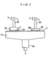
- FIG. 1 shows a basic structure of a polishing apparatus.
- a polishing apparatus comprises a turntable 10, and a top ring 20 positioned above the turntable 10 for holding a semiconductor wafer 2 against the turntable 10.
- the top ring 20 is located in an off-center position with respect to the turntable 10.
- the turntable 10 is rotatable about its own axis as indicated by the arrow A by a motor (not shown) which is coupled through a shaft 10a to the turntable 10.
- a polishing cloth 11 is attached to an upper surface of the turntable 10.
- the top ring 20 is coupled to a motor (not shown) and also to a lifting/lowering cylinder (not shown).
- the top ring 20 is vertically movable and rotatable about its own axis as indicated by the arrows B, C by the motor and the lifting/lowering cylinder.
- the top ring 20 can therefore press the semiconductor wafer 2 against the polishing cloth 11 under a desired pressure.
- the semiconductor wafer 2 is attached to a lower surface of the top ring 20 under a vacuum or the like.
- a guide ring 21 is mounted on the outer circumferential edge of the lower surface of the top ring 20 for preventing the semiconductor wafer 2 from being disengaged from the top ring 20.
- a dressing unit comprises a dressing tool 30 which is positioned above the turntable 10 in diametrically opposite relation to the top ring 20.
- the dressing tool 30 is coupled to a motor (not shown) and also to a lifting/lowering cylinder (not shown).
- the dressing tool 30 is vertically movable and rotatable about its own axis as indicated by the arrows D, E by the motor and the lifting/lowering cylinder.
- the dressing tool 30 has a dressing layer 30a composed of, for example, a diamond grain layer containing diamond grains on its lower surface.
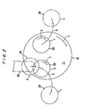
- FIG. 2 is a schematic plan view showing the polishing apparatus shown in FIG. 1.
- the polishing apparatus comprises the turntable 10 at a central part thereof, the top ring 20 and the dressing tool 30 which are disposed above the turntable 10.
- a semiconductor wafer 2 as a workpiece held by the lower surface of the top ring 20 is pressed against the polishing cloth 11 on the turntable 10, and the surface of semiconductor wafer 2 is polished to a flat mirror finish while the top ring 20 and the turntable 10 are rotated.
- the polishing process comes to an end when the semiconductor wafer 2 is polished by a predetermined thickness of a surface layer thereof.
- the polishing properties of the polishing cloth 11 is changed and the polishing performance of the polishing cloth 11 deteriorates.
- the polishing cloth 11 is dressed by the polishing tool 30 to restore its polishing properties.
- the dressing tool 30 which rotates in a direction indicated by the arrow E is pressed against the rotating polishing cloth 11 on the turntable 10 so that the dressing layer 30a is brought in contact with the polishing cloth 11.
- the turntable 10 and the dressing tool 30 are rotated relatively to each other for thereby dressing the polishing cloth 11 to recover its original polishing capability.
- the top ring 20 receives the semiconductor wafer 2 from a robot arm 60 or a pusher (not shown) at a transferring position F, moves to a position above the turntable 10 through a path G, and then presses the semiconductor wafer 2 against the polishing cloth 11 to polish the semiconductor wafer 2 at a polishing position H. After the polishing process finishes, the top ring 20 is returned to the transferring position F through the path G, and the semiconductor wafer 2 which has been polished is transferred from the top ring 20 to the robot arm 60 or a pusher (not shown).
- the top ring 20 receives a new semiconductor wafer to be polished from the robot arm 60 or a pusher, moves to the polishing position H, and the semiconductor wafer 2 is polished at the polishing position H in the same manner as the above.
- the above processes are repeated until polishing processes of one lot of semiconductor wafers are completed.
- the top ring 20 is held in the transferring position F until another lot of semiconductor wafers are carried in.
- a position I which is located on the path G of the top ring 20 and adjacent to the turntable 10 is a standby position of the top ring 20 for maintenance.
- the dressing tool 30 is pressed against the polishing cloth 11 on the turntable 10 at a dressing position J to dress the polishing cloth 11, thus recovering its original polishing capability.
- the dressing tool 30 moves to a standby position L which is located on a path K of the dressing tool 30 and adjacent to the turntable 10, and is held in the standby position L until the next polishing process finishes.
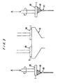
- FIG. 3 shows the top ring 20 and the dressing tool 30 of the polishing apparatus which are held in standby positions I and L, respectively according to a first embodiment of the present invention.
- the polishing apparatus has a cleaning liquid nozzle 40 positioned below the top ring 20 which is held in the standby position I for maintenance.
- the cleaning liquid nozzle 40 supplies cleaning liquid 42 such as pure water to a lower surface of the top ring 20 while the top ring 20 is held in the standby position I.
- the polishing apparatus shown in FIG. 3 also has a cleaning liquid nozzle 41 positioned below the dressing tool 30 which is held in the standby position L.
- the cleaning liquid nozzle 41 supplies cleaning liquid 43 such as pure water to a lower surface of the dressing tool 30 while the dressing tool 30 is held in the standby position L.
- the cleaning liquid 42 is supplied to the lower surface of the top ring 20 from the cleaning liquid nozzle 40 to thus keep the lower surface of the top ring 20 wet.
- the top ring 20 by rotating the top ring 20, it is possible to keep the lower surface of the top ring 20 wet uniformly in its entirety.
- the cleaning liquid 43 is supplied to the lower surface of the dressing tool 30 from the cleaning liquid nozzle 41 to thus keep the lower surface of the dressing tool 30 wet.
- the dressing tool 30 by rotating the dressing tool 30, it is possible to keep the lower surface of the dressing tool 30 wet uniformly in its entirety.
- the cleaning liquid 42 and 43 may continuously be supplied to the top ring 20 and the dressing tool 30, respectively while the top ring 20 and the dressing tool 30 are held in the respective standby positions I and L.
- they may intermittently be ejected from the nozzles 40 and 41 at appropriate intervals selected not to allow the lower surfaces of the top ring 20 and the dressing tool 30 to be dried. Such intermittent ejection can save the cleaning liquid 42 and 43 comprising pure water (deionized water) or the like which is expensive.
- the lower surfaces of the top ring 20 and the dressing tool 30 are cleaned by the cleaning liquid 42 and 43 supplied from the cleaning liquid nozzle 40 and the cleaning liquid nozzle 41.
- these cleaning liquid nozzles may be arranged to keep a certain range such as side surfaces, in addition to the lower surfaces of the top ring 20 and the dressing tool 30 wet.
- a plurality of cleaning liquid nozzles may be provided in each of the standby positions I and L.
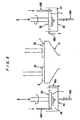
- FIG. 4 shows the top ring 20 and the dressing tool 30 of the polishing apparatus which are held in standby positions I and L, respectively according to a second embodiment of the present invention.
- the polishing apparatus has a container 44 filled with cleaning liquid 46 positioned at a standby position I in which the top ring 20 is held for maintenance, and a container 45 filled with cleaning liquid 47 positioned at a standby position L in which the dressing tool 30 is held.
- the top ring 20 is immersed in the cleaning liquid 46 in the container 44 to thus keep a certain range such as a side surface, in addition to a lower surface of the top ring 20 wet.
- the top ring 20 can effectively be cleaned.
- the dressing tool 30 is held in the standby position L, the dressing tool 30 is immersed in the cleaning liquid 47 in the container 45 to thus keep a certain range such as a side surface, in addition to a lower surface of the dressing tool 30 wet.
- the dressing tool 30 can effectively be cleaned.
- An overflow pipe 48A is provided on the container 44 for keeping the cleaning liquid 46 in the container 44 at a constant level, and the cleaning liquid 46 is supplied to the container 44 through a supply pipe 49A constantly at a small rate or intermittently, and hence the cleaning liquid 46 can be saved.
- an overflow pipe 48B is provided on the container 45 for keeping the cleaning liquid 47 in the container 45 at a constant level, and the cleaning liquid 47 is supplied to the container 45 through a supply pipe 49B constantly at a small rate or intermittently, and hence the cleaning liquid 47 can be saved.
- Drain pipes 49C and 49D are provided on respective bottoms of the containers 44 and 45.
- the top ring 20 and the dressing tool 30 are immersed respectively in the cleaning liquid 46 and the cleaning liquid 47 while the top ring 20 and the dressing tool 30 are held respectively in the standby positions I and L, the top ring 20 and the dressing tool 30 can be kept wet more reliably than they are kept wet by the cleaning nozzles 40 and 41 shown in FIG. 3. Since the cleaning liquid 46 in the container 44 and the cleaning liquid 47 in the container 45 are not scattered around, they do not pollute a polishing room in which the polishing apparatus is installed, and they can be saved.
- both the top ring 20 and the dressing tool 30 are kept wet in the respective standby positions I and L outside of the turntable 10. Therefore, any dry slurry is effectively prevented from being deposited on the top ring 20 and the dressing tool 30 and hence from dropping onto the polishing cloth 11 on the turntable 10.
- either one of the top ring 20 and the dressing tool 30 may be kept wet in some cases.
- the polishing apparatus since the polishing apparatus has a device for keeping the top ring and the dressing tool wet while the top ring and the dressing tool are held in the standby positions outside of the turntable, the top ring and the dressing tool are kept wet while they are in the standby positions, and can also be cleaned by the cleaning liquid supplied from the device. As a result, any dry slurry is prevented from being deposited on the top ring and the dressing tool and hence from dropping onto the polishing cloth on the turntable.
- FIG. 5 shows a detailed structure of a top ring unit incorporated in the polishing apparatus shown in FIGS. 1 through 4.
- a top ring unit 50 in the polishing apparatus generally comprises a motor 51, a top ring drive shaft 52 rotatable about its own axis by the motor 51, and a top ring 20 mounted on the lower end of the top ring drive shaft 52.
- the motor 51 has its output shaft connected to a reduction gear 53 whose drive shaft 54 supports a pulley 55.
- the reduction gear 53 and hence the motor 51 are fixedly mounted on a case 56 which houses the pulley 55.
- the top ring drive shaft 52 is of a hollow structure, and supports thereon a spline bushing 57 and a linear bushing 58 which are fitted thereover.
- a sleeve 59 is fixedly fitted over the spline bushing 57 and the linear bushing 58, and a pulley 61 is fixedly mounted on the sleeve 59.
- the sleeve 59 is rotatably supported by the case 56 through upper and lower bearings 62 and 63.
- a belt 64 is provided between the pulleys 55 and 61.
- the spline bushing 57 is mounted through a bearing in spline grooves 67 defined axially in the outer circumferential surface of the top ring drive shaft 52.
- the spline bushing 57 and the top ring drive shaft 52 are rotatable integrally, but axially slidable relatively to each other.
- the linear bushing 58 supports the top ring drive shaft 52 so as to allow the top ring drive shaft 52 to rotate therein.
- An annular seal 68 is provided between the inner circumferential surface of the lower end of the sleeve 59 and the outer circumferential surface of the top ring drive shaft 52.
- An oil seal 70 is disposed between the case 56 and the sleeve 59.
- a pipe 71 is inserted into the upper end of the top ring drive shaft 52.
- the upper end of the pipe 71 is connected to a joint 72, and the upper end of the joint 72 is connected to a pipe 73.
- the pipe 73 is divided by a division line 73a into an upper portion, and a lower portion which is rotatable with the joint 72.
- the joint 72 is engaged to the drive shaft 52.
- the pipe 71 in the top ring drive shaft 52 is branched into two pipes 71a and 71b which extend out of the top ring drive shaft 52 through respective recesses 75 defined in the lower end of the top ring drive shaft 52 and which are connected to the top ring 20.
- the top ring 20 is connected to a vacuum source through the pipes 71 and 73 to develop a vacuum therein for attracting a semiconductor wafer to a lower surface thereof.
- a cylinder bracket 75 is mounted on an upper end portion of the top ring drive shaft 52 in such a manner that the top ring drive shaft 52 is allowed to rotate with respect to the stationary cylinder bracket 75 and to move axially in unison with the cylinder bracket 75.
- An air cylinder 76 is fixed to the cylinder bracket 75, and has a rod 78 whose lower distal end is fixedly secured to the case 56.
- the case 56 is supported on the upper end of a supporting shaft 80.
- the top ring drive shaft 52 is made of a hardened SUS440C, and has its entire outer circumferential surface coated with a wear-resistant synthetic resin.
- the wear-resistant synthetic resin comprises Teflon (trade mark) graphite synthetic resin.
- Teflon trade mark
- a synthetic resin comprising a mixture of a powder of Teflon (fluorocarbon polymers) and a powder of graphite is sprayed onto the top ring drive shaft 52 in its entirety, and then baked to form a coated layer on the top ring drive shaft 52.
- the coated layer on the top ring drive shaft 52 has a thickness of about 5 ⁇ m.
- the top ring drive shaft 52 thus coated has its increased corrosion resistance against the development of rust thereon.
- top ring unit 50 Operation of the top ring unit 50 will be described below. First, a vacuum is developed in the top ring 20 through the pipes 73 and 71 to attract a semiconductor wafer to the lower surface of the top ring 20. Then, the motor 51 is energized to rotate the top ring drive shaft 52 through a transmission mechanism comprising the pulleys 54, 61 and the belt 64.
- the top ring unit 50 is angularly moved by the supporting shaft 80 to move the top ring 20 above the rotating turntable 10. Thereafter, the air cylinder 76 is actuated to lower the air cylinder 76 and the cylinder bracket 75 with respect to the rod 78 fixed to the case 56, thereby lowering the top ring drive shaft 52 and the top ring 20 to press the semiconductor wafer against the polishing cloth 11 on the turntable 10. The lower surface of the semiconductor wafer is now polished by a combination of chemical polishing and mechanical polishing.
- an abrasive liquid supplied to the polishing cloth is scattered around and applied to the top ring drive shaft 52. Since the top ring drive shaft 52 is coated with the wear-resistant synthetic resin, it does not develop rust by contact with the abrasive liquid.
- the air cylinder 76 is actuated to raise the top ring drive shaft 52 and the top ring 20. Thereafter, the supporting shaft 80 is rotated to angularly move the top ring unit 50 to displace the top ring 20 outside of the turntable 10.
- the present invention has been described as being applied to the top ring drive shaft 52, the principles of the present invention are also applicable to the dressing tool drive shaft 90 (see FIG. 1) for rotating the dressing tool 30 because a dressing liquid such as pure water supplied to dress the polishing cloth with the dressing tool is scattered around and applied to the dressing tool drive shaft 90.
- the overall outer circumferential surface of the top ring drive shaft 52 is coated with the wear-resistant synthetic resin in the illustrated embodiment.
- the wear-resistant synthetic resin may be coated on at least the outer circumferential surface of the top ring drive shaft 52 in the vicinity of its lower end where the abrasive liquid is mainly apt to be applied.
- the wear-resistant synthetic resin may be coated on only the exposed lower portion of the top ring drive shaft 52 which projects out of the lower end of the sleeve 59.
- the wear-resistant synthetic resin coated on the top ring drive shaft 52 and/or the dressing tool drive shaft 90 may be any of various other synthetic resins other than the kind specified above.
- the top ring drive shaft and/or the dressing tool drive shaft which are made of a hardened material and are not highly resistant to rust are prevented from developing rust, even when a liquid such as an abrasive liquid or pure water is applied. Since the top ring drive shaft and/or the dressing tool drive shaft are not plated with metal, but coated with the wear-resistant synthetic resin, they will not cause a metal contamination in the semiconductor fabrication process. In the embodiments, the standby positions of the top ring and the dressing tool are located at the outside of the turntable, however they may be located on or above the turntable.
Landscapes
- Engineering & Computer Science (AREA)
- Mechanical Engineering (AREA)
- Physics & Mathematics (AREA)
- Condensed Matter Physics & Semiconductors (AREA)
- General Physics & Mathematics (AREA)
- Manufacturing & Machinery (AREA)
- Computer Hardware Design (AREA)
- Microelectronics & Electronic Packaging (AREA)
- Power Engineering (AREA)
- Finish Polishing, Edge Sharpening, And Grinding By Specific Grinding Devices (AREA)
Description
- The present invention relates to a polishing apparatus for polishing a workpiece such as a semiconductor wafer by pressing the workpiece held by a top ring against a turntable having a polishing surface thereon, and more particularly to a polishing apparatus which is capable of keeping the top ring and the dressing tool wet while the top ring and the dressing tool are held in respective standby positions outside of the turntable.
- Recent rapid progress in semiconductor device integration demands smaller and smaller wiring patterns or interconnections and also narrower spaces between interconnections which connect active areas. One of the processes available for forming such interconnection is photolithography. Though the photolithographic process can form interconnections that are at most 0.5 µm wide, it requires that surfaces on which pattern images are to be focused by a stepper be as flat as possible because the depth of focus of the optical system is relatively small.
- It is therefore necessary to make the surfaces of semiconductor wafers flat for photolithography. One customary way of flattening the surfaces of semiconductor wafers is to polish them with a polishing apparatus, which process is called Chemical Mechanical polishing.
- Conventionally, a polishing apparatus has a turntable and a top ring which rotate at respective individual speeds. A polishing cloth is attached to the upper surface of the turntable. A semiconductor wafer to be polished is placed on the polishing cloth and clamped between the top ring and the turntable. An abrasive liquid containing abrasive grains is supplied onto the polishing cloth and retained on the polishing cloth. During operation, the top ring exerts a certain pressure on the turntable, and the surface of the semiconductor wafer held against the polishing cloth is therefore polished by a combination of chemical polishing and mechanical polishing to a flat mirror finish while the top ring and the turntable are rotated.
- After, for example, one or more semiconductor wafers have been polished, the polishing cloth is processed to recover its original polishing capability. Various processes have been and are being developed for restoring the polishing cloth, and are collectively called "dressing". The polishing cloth is dressed in order to enable the polishing apparatus to perform a good polishing function at all times without undesired degradation of a polishing performance.
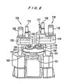
- Next, a conventional polishing apparatus will be described below with reference to FIG. 6.
- As shown in FIG. 6, the polishing apparatus has a
turntable 100, atop ring unit 110, and adressing tool unit 120. Thetop ring unit 110 and thedressing tool unit 120 are disposed above theturntable 100. - The
turntable 100 is rotatable about its own axis by adrive shaft 101 connected thereto. Apolishing cloth 102 made of polyurethane form, nonwoven fabric or the like is attached to an upper surface of theturntable 100. - The
top ring unit 110 has atop ring 111 fixed to a lower end of a topring drive shaft 115 which is rotated about its own axis by amotor 112 through abelt 113. Thetop ring 111 is connected to a vacuum source (not shown) through apipe 117 and an internal passage defined in the topring drive shaft 115 for attracting a semiconductor wafer (not shown) to a lower surface of thetop ring 111 under vacuum. - The
dressing tool unit 120 has a dressing tool 121 fixed to a lower end of a dressingtool drive shaft 125 which is rotated about its own axis by amotor 122 through abelt 123. The dressing tool 121 for dressing thepolishing cloth 102 on theturntable 100 has a brush on a lower surface thereof. The brush may be replaced with a diamond grain layer containing diamond grains, depending on the property of thepolishing cloth 102. - The
top ring unit 110 and thedressing tool unit 120 are angularly movably supported by respective supportingshafts ring drive shaft 115 and the dressingtool drive shaft 125 are vertically movable byair cylinders - In operation, the
top ring 111 which holds a semiconductor wafer on its lower surface is moved above theturntable 100, and lowered by the topring drive shaft 115, thereby pressing the semiconductor wafer against thepolishing cloth 102 on theturntable 100. Theturntable 100 and thetop ring 111 are independently rotated by thedrive shaft 101 and the topring drive shaft 115 at respective speeds for thereby polishing the lower surface of the semiconductor wafer. At this time, an abrasive liquid is being supplied from asupply pipe 150 onto thepolishing cloth 102. - After the semiconductor wafer is polished, the dressing tool 121 is moved above the
turntable 100, and lowered and pressed against thepolishing cloth 102 on theturntable 100 by the dressingtool driving shaft 125. Theturntable 100 and the dressing tool 121 are independently rotated by thedrive shaft 101 and the dressingtool drive shaft 125 at respective speeds for thereby dressing the surface of thepolishing cloth 102. At this time, a dressing liquid such as pure water (deionized water) is being supplied from a supply pipe (not shown) onto thepolishing cloth 102. - In the polishing apparatus shown in FIG. 6, the
top ring 111 and the dressing tool 121 are swingable about the supportingshafts top ring 111 and the dressing tool 121 are positioned in respective standby positions outside of theturntable 100. - When the
top ring 111 is held in the standby position for maintenance and the dressing tool 121 is held in the standby position, they are not kept wet. Therefore, any slurry attached to thetop ring 111 and the dressing tool 121 is dried. When thetop ring 111 and the dressing tool 121 are moved to a position over theturntable 100, the dry slurry tends to fall onto thepolishing cloth 102 on theturntable 100, thus adversely affecting the polishing action on the workpiece to be polished. - Further, the top
ring drive shaft 115 and the dressingtool drive shaft 125 need to have bearing surfaces which are rotatably supported by the bearings. Therefore, it is necessary that the topring drive shaft 115 and the dressingtool drive shaft 125 be made of a hardened SUS440C. Since the topring drive shaft 115 and the dressingtool drive shaft 125 are hardened, their antirust properties are reduced. - The top
ring drive shaft 115 and the dressingtool drive shaft 125 are positioned for exposure to the abrasive liquid and pure water, thus the abrasive liquid and pure water tend to be attached to the topring drive shaft 115 and the dressingtool drive shaft 125. When the abrasive liquid and pure water are attached to the topring drive shaft 115 and the dressingtool drive shaft 125, they will develop rust on their surfaces. - The top
ring drive shaft 115 and the dressingtool drive shaft 125 may be plated with chromium for preventing rust from being developed thereon. However, the plated layer of chromium may possibly be peeled off, resulting in a chromium contamination in the semiconductor fabrication process. - Alternatively, the top
ring drive shaft 115 and the dressingtool drive shaft 125 may be made of a ceramic material for preventing rust from being developed thereon. However, since the ceramic materials are expensive, manufacturing cost of the polishing apparatus increases. - In accordance with the present invention a polishing apparatus as set forth In
claim 1 is provided. Preferred embodiments of the invention are disclosed in the dependent claims. - It is therefore an object of the present invention to provide a polishing apparatus which is capable of keeping a top ring and a dressing tool wet with a cleaning liquid while the top ring and the dressing tool are held in respective standby positions outside of a turntable, for thereby removing any slurry that has been attached to the top ring and the dressing tool and preventing the top ring and the dressing tool from being dried.
- According to the present invention, there is provided a polishing apparatus comprising: a turntable having a polishing surface thereon; a top ring for holding a workpiece to be polished and pressing the workpiece against the polishing surface on the turntable, the top ring being movable between a polishing position inside of the turntable and a standby position outside of the turntable; and a first device for keeping at least a lower surface of the top ring wet while the top ring is in the standby position.
- Preferably, the polishing apparatus further comprises: a dressing tool for dressing the polishing surface on the turntable, the dressing tool being movable between a dressing position inside of the turntable and a standby position outside of the turntable; and a second device for keeping at least a lower surface of the dressing tool wet while the dressing tool is in the standby position.
- The above and other objects, preferred features, and advantages of the present invention will become apparent from the following description when taken in conjunction with the accompanying drawings which illustrate preferred embodiments of the present invention by way of example.
-
- FIG. 1 is a front elevational view showing a basic structure of a polishing apparatus according to a first embodiment of the present invention;
- FIG. 2 is a plan view of a polishing apparatus shown in FIG. 1;
- FIG. 3 is a front elevational view of a polishing apparatus according to a first embodiment of the present invention;
- FIG. 4 is a front elevational view of a polishing apparatus according to a second embodiment of the present invention;
- FIG. 5 is a cross-sectional view showing a top ring unit of the polishing apparatus according to the first and second embodiments of the present invention; and
- FIG. 6 is a perspective view of a conventional polishing apparatus.
-
- A polishing apparatus according to a first embodiment of the present invention will be described below with reference to FIGS. 1 through 3.
- FIG. 1 shows a basic structure of a polishing apparatus. As shown in FIG. 1, a polishing apparatus comprises a
turntable 10, and atop ring 20 positioned above theturntable 10 for holding a semiconductor wafer 2 against theturntable 10. Thetop ring 20 is located in an off-center position with respect to theturntable 10. Theturntable 10 is rotatable about its own axis as indicated by the arrow A by a motor (not shown) which is coupled through ashaft 10a to theturntable 10. A polishingcloth 11 is attached to an upper surface of theturntable 10. - The
top ring 20 is coupled to a motor (not shown) and also to a lifting/lowering cylinder (not shown). Thetop ring 20 is vertically movable and rotatable about its own axis as indicated by the arrows B, C by the motor and the lifting/lowering cylinder. Thetop ring 20 can therefore press the semiconductor wafer 2 against the polishingcloth 11 under a desired pressure. The semiconductor wafer 2 is attached to a lower surface of thetop ring 20 under a vacuum or the like. Aguide ring 21 is mounted on the outer circumferential edge of the lower surface of thetop ring 20 for preventing the semiconductor wafer 2 from being disengaged from thetop ring 20. - A dressing unit comprises a
dressing tool 30 which is positioned above theturntable 10 in diametrically opposite relation to thetop ring 20. The dressingtool 30 is coupled to a motor (not shown) and also to a lifting/lowering cylinder (not shown). The dressingtool 30 is vertically movable and rotatable about its own axis as indicated by the arrows D, E by the motor and the lifting/lowering cylinder. The dressingtool 30 has adressing layer 30a composed of, for example, a diamond grain layer containing diamond grains on its lower surface. - FIG. 2 is a schematic plan view showing the polishing apparatus shown in FIG. 1. As shown in FIG. 2, the polishing apparatus comprises the
turntable 10 at a central part thereof, thetop ring 20 and thedressing tool 30 which are disposed above theturntable 10. A semiconductor wafer 2 as a workpiece held by the lower surface of thetop ring 20 is pressed against the polishingcloth 11 on theturntable 10, and the surface of semiconductor wafer 2 is polished to a flat mirror finish while thetop ring 20 and theturntable 10 are rotated. The polishing process comes to an end when the semiconductor wafer 2 is polished by a predetermined thickness of a surface layer thereof. When the polishing process is completed, the polishing properties of the polishingcloth 11 is changed and the polishing performance of the polishingcloth 11 deteriorates. Therefore, the polishingcloth 11 is dressed by the polishingtool 30 to restore its polishing properties. The dressingtool 30 which rotates in a direction indicated by the arrow E is pressed against the rotating polishingcloth 11 on theturntable 10 so that thedressing layer 30a is brought in contact with the polishingcloth 11. Theturntable 10 and thedressing tool 30 are rotated relatively to each other for thereby dressing the polishingcloth 11 to recover its original polishing capability. - In the polishing apparatus, as shown in FIG. 2, the
top ring 20 receives the semiconductor wafer 2 from arobot arm 60 or a pusher (not shown) at a transferring position F, moves to a position above theturntable 10 through a path G, and then presses the semiconductor wafer 2 against the polishingcloth 11 to polish the semiconductor wafer 2 at a polishing position H. After the polishing process finishes, thetop ring 20 is returned to the transferring position F through the path G, and the semiconductor wafer 2 which has been polished is transferred from thetop ring 20 to therobot arm 60 or a pusher (not shown). Thereafter, thetop ring 20 receives a new semiconductor wafer to be polished from therobot arm 60 or a pusher, moves to the polishing position H, and the semiconductor wafer 2 is polished at the polishing position H in the same manner as the above. The above processes are repeated until polishing processes of one lot of semiconductor wafers are completed. After polishing processes of one lot of the semiconductor wafers are completed, thetop ring 20 is held in the transferring position F until another lot of semiconductor wafers are carried in. A position I which is located on the path G of thetop ring 20 and adjacent to theturntable 10 is a standby position of thetop ring 20 for maintenance. - On the other hand, the dressing
tool 30 is pressed against the polishingcloth 11 on theturntable 10 at a dressing position J to dress the polishingcloth 11, thus recovering its original polishing capability. After dressing, the dressingtool 30 moves to a standby position L which is located on a path K of the dressingtool 30 and adjacent to theturntable 10, and is held in the standby position L until the next polishing process finishes. - FIG. 3 shows the
top ring 20 and thedressing tool 30 of the polishing apparatus which are held in standby positions I and L, respectively according to a first embodiment of the present invention. As shown in FIG. 3, the polishing apparatus has a cleaningliquid nozzle 40 positioned below thetop ring 20 which is held in the standby position I for maintenance. The cleaningliquid nozzle 40supplies cleaning liquid 42 such as pure water to a lower surface of thetop ring 20 while thetop ring 20 is held in the standby position I. The polishing apparatus shown in FIG. 3 also has a cleaning liquid nozzle 41 positioned below the dressingtool 30 which is held in the standby position L. The cleaning liquid nozzle 41supplies cleaning liquid 43 such as pure water to a lower surface of the dressingtool 30 while the dressingtool 30 is held in the standby position L. - In the polishing apparatus having the above structure, while the
top ring 20 is held in the standby position I for maintenance, the cleaningliquid 42 is supplied to the lower surface of thetop ring 20 from the cleaningliquid nozzle 40 to thus keep the lower surface of thetop ring 20 wet. At this time, by rotating thetop ring 20, it is possible to keep the lower surface of thetop ring 20 wet uniformly in its entirety. - While the dressing
tool 30 is held in the standby position L, the cleaningliquid 43 is supplied to the lower surface of the dressingtool 30 from the cleaning liquid nozzle 41 to thus keep the lower surface of the dressingtool 30 wet. At this time, by rotating the dressingtool 30, it is possible to keep the lower surface of the dressingtool 30 wet uniformly in its entirety. - Since supply of the cleaning
liquid liquid nozzles 40 and 41 is primarily for the purpose of keeping the lower surfaces of thetop ring 20 and thedressing tool 30 wet, the cleaningliquid top ring 20 and thedressing tool 30, respectively while thetop ring 20 and thedressing tool 30 are held in the respective standby positions I and L. However, in order to save the cleaningliquid nozzles 40 and 41 at appropriate intervals selected not to allow the lower surfaces of thetop ring 20 and thedressing tool 30 to be dried. Such intermittent ejection can save the cleaningliquid - In the embodiment shown in FIG. 3, the lower surfaces of the
top ring 20 and thedressing tool 30 are cleaned by the cleaningliquid liquid nozzle 40 and the cleaning liquid nozzle 41. However, these cleaning liquid nozzles may be arranged to keep a certain range such as side surfaces, in addition to the lower surfaces of thetop ring 20 and thedressing tool 30 wet. Further, a plurality of cleaning liquid nozzles may be provided in each of the standby positions I and L. - FIG. 4 shows the
top ring 20 and thedressing tool 30 of the polishing apparatus which are held in standby positions I and L, respectively according to a second embodiment of the present invention. As shown in FIG. 4, the polishing apparatus has a container 44 filled with cleaningliquid 46 positioned at a standby position I in which thetop ring 20 is held for maintenance, and acontainer 45 filled with cleaningliquid 47 positioned at a standby position L in which thedressing tool 30 is held. - In the polishing apparatus having the above structure, while the
top ring 20 is held in the standby position I for maintenance, thetop ring 20 is immersed in the cleaningliquid 46 in the container 44 to thus keep a certain range such as a side surface, in addition to a lower surface of thetop ring 20 wet. At this time, by rotating thetop ring 20, thetop ring 20 can effectively be cleaned. While the dressingtool 30 is held in the standby position L, the dressingtool 30 is immersed in the cleaningliquid 47 in thecontainer 45 to thus keep a certain range such as a side surface, in addition to a lower surface of the dressingtool 30 wet. At this time, by rotating the dressingtool 30, the dressingtool 30 can effectively be cleaned. - An
overflow pipe 48A is provided on the container 44 for keeping the cleaningliquid 46 in the container 44 at a constant level, and the cleaningliquid 46 is supplied to the container 44 through asupply pipe 49A constantly at a small rate or intermittently, and hence the cleaningliquid 46 can be saved. Similarly, anoverflow pipe 48B is provided on thecontainer 45 for keeping the cleaningliquid 47 in thecontainer 45 at a constant level, and the cleaningliquid 47 is supplied to thecontainer 45 through asupply pipe 49B constantly at a small rate or intermittently, and hence the cleaningliquid 47 can be saved.Drain pipes containers 44 and 45. - Inasmuch as the
top ring 20 and thedressing tool 30 are immersed respectively in the cleaningliquid 46 and the cleaningliquid 47 while thetop ring 20 and thedressing tool 30 are held respectively in the standby positions I and L, thetop ring 20 and thedressing tool 30 can be kept wet more reliably than they are kept wet by the cleaningnozzles 40 and 41 shown in FIG. 3. Since the cleaningliquid 46 in the container 44 and the cleaningliquid 47 in thecontainer 45 are not scattered around, they do not pollute a polishing room in which the polishing apparatus is installed, and they can be saved. - In the above embodiments in FIGS. 3 and 4, both the
top ring 20 and thedressing tool 30 are kept wet in the respective standby positions I and L outside of theturntable 10. Therefore, any dry slurry is effectively prevented from being deposited on thetop ring 20 and thedressing tool 30 and hence from dropping onto the polishingcloth 11 on theturntable 10. However, either one of thetop ring 20 and thedressing tool 30 may be kept wet in some cases. - With the arrangements of the first and second embodiments of the present invention, as described above, since the polishing apparatus has a device for keeping the top ring and the dressing tool wet while the top ring and the dressing tool are held in the standby positions outside of the turntable, the top ring and the dressing tool are kept wet while they are in the standby positions, and can also be cleaned by the cleaning liquid supplied from the device. As a result, any dry slurry is prevented from being deposited on the top ring and the dressing tool and hence from dropping onto the polishing cloth on the turntable. In another aspect of this invention, in the case where a backing pad (elastic pad) is mounted to the lower surface of the top ring, by keeping the top ring wet, the wafer adheres more reliably to the lower surface of the top ring, hence the polishing performance is increased.
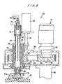
- FIG. 5 shows a detailed structure of a top ring unit incorporated in the polishing apparatus shown in FIGS. 1 through 4.
- As shown in FIG. 5, a
top ring unit 50 in the polishing apparatus generally comprises amotor 51, a topring drive shaft 52 rotatable about its own axis by themotor 51, and atop ring 20 mounted on the lower end of the topring drive shaft 52. - The
motor 51 has its output shaft connected to areduction gear 53 whosedrive shaft 54 supports apulley 55. Thereduction gear 53 and hence themotor 51 are fixedly mounted on acase 56 which houses thepulley 55. - The top
ring drive shaft 52 is of a hollow structure, and supports thereon aspline bushing 57 and alinear bushing 58 which are fitted thereover. Asleeve 59 is fixedly fitted over thespline bushing 57 and thelinear bushing 58, and apulley 61 is fixedly mounted on thesleeve 59. Thesleeve 59 is rotatably supported by thecase 56 through upper andlower bearings belt 64 is provided between thepulleys - The
spline bushing 57 is mounted through a bearing inspline grooves 67 defined axially in the outer circumferential surface of the topring drive shaft 52. Thespline bushing 57 and the topring drive shaft 52 are rotatable integrally, but axially slidable relatively to each other. Thelinear bushing 58 supports the topring drive shaft 52 so as to allow the topring drive shaft 52 to rotate therein. - An
annular seal 68 is provided between the inner circumferential surface of the lower end of thesleeve 59 and the outer circumferential surface of the topring drive shaft 52. Anoil seal 70 is disposed between thecase 56 and thesleeve 59. - A
pipe 71 is inserted into the upper end of the topring drive shaft 52. The upper end of thepipe 71 is connected to a joint 72, and the upper end of the joint 72 is connected to a pipe 73. The pipe 73 is divided by adivision line 73a into an upper portion, and a lower portion which is rotatable with the joint 72. The joint 72 is engaged to thedrive shaft 52. Thepipe 71 in the topring drive shaft 52 is branched into twopipes ring drive shaft 52 throughrespective recesses 75 defined in the lower end of the topring drive shaft 52 and which are connected to thetop ring 20. Thetop ring 20 is connected to a vacuum source through thepipes 71 and 73 to develop a vacuum therein for attracting a semiconductor wafer to a lower surface thereof. - A
cylinder bracket 75 is mounted on an upper end portion of the topring drive shaft 52 in such a manner that the topring drive shaft 52 is allowed to rotate with respect to thestationary cylinder bracket 75 and to move axially in unison with thecylinder bracket 75. Anair cylinder 76 is fixed to thecylinder bracket 75, and has arod 78 whose lower distal end is fixedly secured to thecase 56. Thecase 56 is supported on the upper end of a supportingshaft 80. - The top
ring drive shaft 52 is made of a hardened SUS440C, and has its entire outer circumferential surface coated with a wear-resistant synthetic resin. - In the illustrated embodiment, the wear-resistant synthetic resin comprises Teflon (trade mark) graphite synthetic resin. Specifically, a synthetic resin comprising a mixture of a powder of Teflon (fluorocarbon polymers) and a powder of graphite is sprayed onto the top
ring drive shaft 52 in its entirety, and then baked to form a coated layer on the topring drive shaft 52. The coated layer on the topring drive shaft 52 has a thickness of about 5 µm. - The top
ring drive shaft 52 thus coated has its increased corrosion resistance against the development of rust thereon. - Operation of the
top ring unit 50 will be described below. First, a vacuum is developed in thetop ring 20 through thepipes 73 and 71 to attract a semiconductor wafer to the lower surface of thetop ring 20. Then, themotor 51 is energized to rotate the topring drive shaft 52 through a transmission mechanism comprising thepulleys belt 64. - The
top ring unit 50 is angularly moved by the supportingshaft 80 to move thetop ring 20 above the rotatingturntable 10. Thereafter, theair cylinder 76 is actuated to lower theair cylinder 76 and thecylinder bracket 75 with respect to therod 78 fixed to thecase 56, thereby lowering the topring drive shaft 52 and thetop ring 20 to press the semiconductor wafer against the polishingcloth 11 on theturntable 10. The lower surface of the semiconductor wafer is now polished by a combination of chemical polishing and mechanical polishing. - At this time, an abrasive liquid supplied to the polishing cloth is scattered around and applied to the top
ring drive shaft 52. Since the topring drive shaft 52 is coated with the wear-resistant synthetic resin, it does not develop rust by contact with the abrasive liquid. - Even when the wear-resistant synthetic resin is partly peeled off from the top
ring drive shaft 52, it does not adversely affect the semiconductor fabrication environment as it is not metal. - After the semiconductor wafer is polished, the
air cylinder 76 is actuated to raise the topring drive shaft 52 and thetop ring 20. Thereafter, the supportingshaft 80 is rotated to angularly move thetop ring unit 50 to displace thetop ring 20 outside of theturntable 10. - Although the present invention has been described as being applied to the top
ring drive shaft 52, the principles of the present invention are also applicable to the dressing tool drive shaft 90 (see FIG. 1) for rotating the dressingtool 30 because a dressing liquid such as pure water supplied to dress the polishing cloth with the dressing tool is scattered around and applied to the dressingtool drive shaft 90. - The overall outer circumferential surface of the top
ring drive shaft 52 is coated with the wear-resistant synthetic resin in the illustrated embodiment. However, the wear-resistant synthetic resin may be coated on at least the outer circumferential surface of the topring drive shaft 52 in the vicinity of its lower end where the abrasive liquid is mainly apt to be applied. Specifically, the wear-resistant synthetic resin may be coated on only the exposed lower portion of the topring drive shaft 52 which projects out of the lower end of thesleeve 59. This is because any liquid such as the abrasive liquid does not enter thecase 56 and the portion of the topring drive shaft 52 which projects upwardly from thecase 56 is spaced away from thetop ring 20, and hence the exposed lower portion of the topring drive shaft 52 is most likely to develop rust. The same holds true for the dressing tool drive shaft 90 (see FIG. 1). - The wear-resistant synthetic resin coated on the top
ring drive shaft 52 and/or the dressingtool drive shaft 90 may be any of various other synthetic resins other than the kind specified above. - As described above, the top ring drive shaft and/or the dressing tool drive shaft which are made of a hardened material and are not highly resistant to rust are prevented from developing rust, even when a liquid such as an abrasive liquid or pure water is applied. Since the top ring drive shaft and/or the dressing tool drive shaft are not plated with metal, but coated with the wear-resistant synthetic resin, they will not cause a metal contamination in the semiconductor fabrication process. In the embodiments, the standby positions of the top ring and the dressing tool are located at the outside of the turntable, however they may be located on or above the turntable.
- Although certain preferred embodiments of the present invention have been shown and described in detail, it should be understood that various changes and modifications may be made therein without departing from the scope of the appended claims.
Claims (11)
- A polishing apparatus comprising:a turntable (10) having a polishing surface thereon;a top ring (20) for holding a workpiece (2) to be polished and pressing the workpiece (2) against said polishing surface on said turntable (10), said top ring (20) being movable between a polishing position inside of said turntable (10) and a standby position ; anda first device (40;44) for keeping at least a lower surface of said top ring (20) wet while said top ring is in said standby position.
- A polishing apparatus according to claim 1, further comprising:a dressing tool (30) for dressing said polishing surface on said turntable (10), said dressing tool (30) being movable between a dressing position inside of said turntable (10) and a standby position; anda second device (41;45) for keeping at least a lower surface of said dressing tool (30) wet while said dressing tool is in said standby position.
- A polishing apparatus according to claim 1 or 2, wherein said first device (40;44) comprises one of a nozzle (41) for supplying a cleaning liquid (42) to at least said lower surface of said top ring (20), and a container (44) filled with a cleaning liquid (46) for immersing therein at least said lower surface of said top ring (20).
- A polishing apparatus according to claim 3, wherein said nozzle (40) intermittently ejects said cleaning liquid (42).
- A polishing apparatus according to any one of claims 1 to 4, wherein said top ring (20) is rotated while at least said lower surface thereof is kept wet by said first device (40;44).
- A polishing apparatus according to claim 2, wherein said second device (41;45) comprises one of a nozzle (41) for supplying a cleaning liquid (43) to at least said lower surface of said dressing tool (20), and a container (45) filled with a cleaning liquid (47) for immersing therein at least said lower surface of said dressing tool (20).
- A polishing apparatus according to claim 6, wherein said nozzle (41) intermittently ejects said cleaning liquid (43).
- A polishing apparatus according to claim 2, wherein said dressing tool (30) is rotated while at least said lower surface thereof is kept wet by said second device (41;45).
- A polishing apparatus according to any one of the preceding claims, further comprising:an abrasive liquid supply device for supplying an abrasive liquid to said polishing surface on said turntable (10); anda top ring drive shaft (52) for rotating said top ring (20), said top ring drive shaft (52) having a lower portion where the abrasive liquid tends to be applied, at least said lower portion of said top ring drive shaft (52) being coated with a wear-resistant synthetic resin.
- A polishing apparatus according to claim 2, further comprising:a dressing liquid supply device for supplying a dressing liquid to said polishing surface on said turntable (10); anda dressing tool drive shaft (90) for rotating said dressing tool (30), said dressing tool drive shaft (90) having a lower portion where the dressing liquid tends to be applied, at least said lower portion of said dressing tool drive shaft (30) being coated with a wear-resistant synthetic resin.
- A polishing apparatus according to claim 9 or 10, wherein said wear-resistant synthetic resin comprises a mixture of a powder of fluorocarbon polymers and a powder of graphite.
Applications Claiming Priority (6)
| Application Number | Priority Date | Filing Date | Title |
|---|---|---|---|
| JP4419996 | 1996-02-05 | ||
| JP8044199A JPH09207065A (en) | 1996-02-05 | 1996-02-05 | Polishing device |
| JP44199/96 | 1996-02-05 | ||
| JP90569/96 | 1996-03-19 | ||
| JP9056996 | 1996-03-19 | ||
| JP9056996A JP3720451B2 (en) | 1996-03-19 | 1996-03-19 | Polishing apparatus and operation method thereof |
Publications (2)
| Publication Number | Publication Date |
|---|---|
| EP0787561A1 EP0787561A1 (en) | 1997-08-06 |
| EP0787561B1 true EP0787561B1 (en) | 2002-01-09 |
Family
ID=26384047
Family Applications (1)
| Application Number | Title | Priority Date | Filing Date |
|---|---|---|---|
| EP97101800A Expired - Lifetime EP0787561B1 (en) | 1996-02-05 | 1997-02-05 | Polishing apparatus |
Country Status (4)
| Country | Link |
|---|---|
| US (1) | US5839947A (en) |
| EP (1) | EP0787561B1 (en) |
| KR (1) | KR100456803B1 (en) |
| DE (1) | DE69709461T2 (en) |
Families Citing this family (31)
| Publication number | Priority date | Publication date | Assignee | Title |
|---|---|---|---|---|
| JP3724869B2 (en) * | 1995-10-09 | 2005-12-07 | 株式会社荏原製作所 | Polishing apparatus and method |
| US6050884A (en) | 1996-02-28 | 2000-04-18 | Ebara Corporation | Polishing apparatus |
| JP3679871B2 (en) * | 1996-09-04 | 2005-08-03 | 株式会社荏原製作所 | Polishing apparatus and transfer robot |
| JPH10156705A (en) * | 1996-11-29 | 1998-06-16 | Sumitomo Metal Ind Ltd | Polishing device and polishing method |
| EP0868973B1 (en) * | 1997-02-04 | 2003-06-25 | Ebara Corporation | Workpiece holding device and polishing apparatus therewith |
| US5975994A (en) * | 1997-06-11 | 1999-11-02 | Micron Technology, Inc. | Method and apparatus for selectively conditioning a polished pad used in planarizng substrates |
| US5964653A (en) | 1997-07-11 | 1999-10-12 | Applied Materials, Inc. | Carrier head with a flexible membrane for a chemical mechanical polishing system |
| JP3795198B2 (en) * | 1997-09-10 | 2006-07-12 | 株式会社荏原製作所 | Substrate holding device and polishing apparatus provided with the substrate holding device |
| US6780095B1 (en) | 1997-12-30 | 2004-08-24 | Micron Technology, Inc. | Method and apparatus for mechanical and chemical-mechanical planarization of microelectronic substrates |
| US6139402A (en) | 1997-12-30 | 2000-10-31 | Micron Technology, Inc. | Method and apparatus for mechanical and chemical-mechanical planarization of microelectronic substrates |
| US6135868A (en) * | 1998-02-11 | 2000-10-24 | Applied Materials, Inc. | Groove cleaning device for chemical-mechanical polishing |
| US6123612A (en) | 1998-04-15 | 2000-09-26 | 3M Innovative Properties Company | Corrosion resistant abrasive article and method of making |
| US6089960A (en) * | 1998-06-03 | 2000-07-18 | One Source Manufacturing | Semiconductor wafer polishing mechanism |
| US6129610A (en) * | 1998-08-14 | 2000-10-10 | International Business Machines Corporation | Polish pressure modulation in CMP to preferentially polish raised features |
| US6033290A (en) * | 1998-09-29 | 2000-03-07 | Applied Materials, Inc. | Chemical mechanical polishing conditioner |
| US6217430B1 (en) | 1998-11-02 | 2001-04-17 | Applied Materials, Inc. | Pad conditioner cleaning apparatus |
| US6358124B1 (en) | 1998-11-02 | 2002-03-19 | Applied Materials, Inc. | Pad conditioner cleaning apparatus |
| US6358128B1 (en) * | 1999-03-05 | 2002-03-19 | Ebara Corporation | Polishing apparatus |
| JP4030247B2 (en) | 1999-05-17 | 2008-01-09 | 株式会社荏原製作所 | Dressing device and polishing device |
| EP1077108B1 (en) * | 1999-08-18 | 2006-12-20 | Ebara Corporation | Polishing method and polishing apparatus |
| US7367872B2 (en) * | 2003-04-08 | 2008-05-06 | Applied Materials, Inc. | Conditioner disk for use in chemical mechanical polishing |
| ITMI20041788A1 (en) * | 2004-09-20 | 2004-12-20 | St Microelectronics Srl | "MULTI-STATION ROTARY MACHINE FOR THE SANDING OF WAFER OF SEMICONDUCTOR ELECTRONIC COMPONENTS" |
| US7338569B2 (en) * | 2004-09-29 | 2008-03-04 | Agere Systems Inc. | Method and system of using offset gage for CMP polishing pad alignment and adjustment |
| JP2007111283A (en) * | 2005-10-21 | 2007-05-10 | Timothy Tamio Nemoto | Crown grinding device |
| JP5405887B2 (en) * | 2009-04-27 | 2014-02-05 | ルネサスエレクトロニクス株式会社 | Polishing apparatus and polishing method |
| CN102528653B (en) * | 2010-12-30 | 2014-11-05 | 中芯国际集成电路制造(上海)有限公司 | Fixed type particle grinding device and grinding method thereof |
| CN102294647A (en) * | 2011-09-07 | 2011-12-28 | 清华大学 | Chemical mechanical polishing method |
| CN102320026A (en) * | 2011-09-07 | 2012-01-18 | 清华大学 | Chemical mechanical polishing method |
| TWI577497B (en) * | 2012-10-31 | 2017-04-11 | Ebara Corp | Grinding device |
| CN103481195A (en) * | 2013-09-03 | 2014-01-01 | 宇环数控机床股份有限公司 | Multi-shaft driving device for single-face grinding polisher |
| CN107900825A (en) * | 2017-10-30 | 2018-04-13 | 马鞍山市盛力锁业科技有限公司 | A kind of lock body process equipment |
Family Cites Families (17)
| Publication number | Priority date | Publication date | Assignee | Title |
|---|---|---|---|---|
| US4193226A (en) * | 1977-09-21 | 1980-03-18 | Kayex Corporation | Polishing apparatus |
| EP0100648A3 (en) * | 1982-07-29 | 1985-08-07 | Yoshiaki Nagaura | Holding a workpiece |
| DE3243617A1 (en) * | 1982-11-25 | 1984-05-30 | Hermetic-Pumpen Gmbh, 7803 Gundelfingen | Pump for conveying highly corrosive media |
| IT1214563B (en) * | 1986-11-21 | 1990-01-18 | Ausimont Spa | POLYTETRAFLUOETHYLENE BASED COMPOSITION SUITABLE FOR OBTAINING A SELF-LUBRICATING LAYER ON POROUS BRONZE SUPPORTS. |
| JPH0615565A (en) * | 1991-12-18 | 1994-01-25 | Shin Etsu Handotai Co Ltd | Automatic wafer lapping machine |
| US5329732A (en) * | 1992-06-15 | 1994-07-19 | Speedfam Corporation | Wafer polishing method and apparatus |
| US5455080A (en) * | 1992-08-26 | 1995-10-03 | Armco Inc. | Metal substrate with enhanced corrosion resistance and improved paint adhesion |
| US5384986A (en) * | 1992-09-24 | 1995-01-31 | Ebara Corporation | Polishing apparatus |
| US5491185A (en) * | 1993-05-14 | 1996-02-13 | The United States Of America As Represented By The Secretary Of The Navy | Epoxy self-priming topcoats |
| KR100390293B1 (en) * | 1993-09-21 | 2003-09-02 | 가부시끼가이샤 도시바 | Polishing device |
| US5653623A (en) * | 1993-12-14 | 1997-08-05 | Ebara Corporation | Polishing apparatus with improved exhaust |
| KR0132274B1 (en) * | 1994-05-16 | 1998-04-11 | 김광호 | Polishing apparatus of semiconductor wafer |
| JPH08168953A (en) * | 1994-12-16 | 1996-07-02 | Ebara Corp | Dressing device |
| US5527424A (en) * | 1995-01-30 | 1996-06-18 | Motorola, Inc. | Preconditioner for a polishing pad and method for using the same |
| JP3594357B2 (en) * | 1995-04-10 | 2004-11-24 | 株式会社荏原製作所 | Polishing method and apparatus |
| US5578529A (en) * | 1995-06-02 | 1996-11-26 | Motorola Inc. | Method for using rinse spray bar in chemical mechanical polishing |
| JPH0911120A (en) * | 1995-06-26 | 1997-01-14 | Texas Instr Inc <Ti> | Method and device for adjustment of cmp grinding pad |
-
1997
- 1997-02-05 DE DE69709461T patent/DE69709461T2/en not_active Expired - Lifetime
- 1997-02-05 US US08/795,511 patent/US5839947A/en not_active Expired - Lifetime
- 1997-02-05 EP EP97101800A patent/EP0787561B1/en not_active Expired - Lifetime
- 1997-02-05 KR KR1019970003456A patent/KR100456803B1/en not_active IP Right Cessation
Also Published As
| Publication number | Publication date |
|---|---|
| KR970067676A (en) | 1997-10-13 |
| US5839947A (en) | 1998-11-24 |
| EP0787561A1 (en) | 1997-08-06 |
| DE69709461T2 (en) | 2002-09-26 |
| KR100456803B1 (en) | 2005-05-09 |
| DE69709461D1 (en) | 2002-02-14 |
Similar Documents
| Publication | Publication Date | Title |
|---|---|---|
| EP0787561B1 (en) | Polishing apparatus | |
| USRE38228E1 (en) | Polishing apparatus | |
| EP0792721B1 (en) | Polishing apparatus | |
| US5860181A (en) | Method of and apparatus for cleaning workpiece | |
| US5618227A (en) | Apparatus for polishing wafer | |
| US5857898A (en) | Method of and apparatus for dressing polishing cloth | |
| USRE39195E1 (en) | Polishing pad refurbisher for in situ, real-time conditioning and cleaning of a polishing pad used in chemical-mechanical polishing of microelectronic substrates | |
| EP1250215B1 (en) | System and method for controlled polishing and planarization of semiconductor wafers | |
| US6354918B1 (en) | Apparatus and method for polishing workpiece | |
| EP1063055A2 (en) | Apparatus and method for chemical mechanical polishing | |
| GB2331948A (en) | Polishing machine for flattening substrate surface. | |
| US20050048880A1 (en) | Chemical mechanical polishing system having multiple polishing stations and providing relative linear polishing motion | |
| EP0816017B1 (en) | Method and apparatus for dressing polishing cloth | |
| US6447374B1 (en) | Chemical mechanical planarization system | |
| US6506098B1 (en) | Self-cleaning slurry arm on a CMP tool | |
| EP0827809A1 (en) | Polishing apparatus | |
| US6607427B2 (en) | Dressing apparatus and polishing apparatus | |
| US20030140943A1 (en) | Apparatus and methods to clean copper contamination on wafer edge | |
| JP2002079461A (en) | Polishing device | |
| US6398626B1 (en) | Polishing apparatus | |
| US20020016136A1 (en) | Conditioner for polishing pads | |
| EP0796702B1 (en) | Polishing apparatus and method | |
| JPH09207065A (en) | Polishing device | |
| JPH10235659A (en) | Surface treating device for cylindrical mold |
Legal Events
| Date | Code | Title | Description |
|---|---|---|---|
| PUAI | Public reference made under article 153(3) epc to a published international application that has entered the european phase |
Free format text: ORIGINAL CODE: 0009012 |
|
| AK | Designated contracting states |
Kind code of ref document: A1 Designated state(s): DE FR |
|
| 17P | Request for examination filed |
Effective date: 19980206 |
|
| 17Q | First examination report despatched |
Effective date: 19990716 |
|
| GRAG | Despatch of communication of intention to grant |
Free format text: ORIGINAL CODE: EPIDOS AGRA |
|
| GRAG | Despatch of communication of intention to grant |
Free format text: ORIGINAL CODE: EPIDOS AGRA |
|
| GRAH | Despatch of communication of intention to grant a patent |
Free format text: ORIGINAL CODE: EPIDOS IGRA |
|
| GRAH | Despatch of communication of intention to grant a patent |
Free format text: ORIGINAL CODE: EPIDOS IGRA |
|
| GRAA | (expected) grant |
Free format text: ORIGINAL CODE: 0009210 |
|
| AK | Designated contracting states |
Kind code of ref document: B1 Designated state(s): DE FR |
|
| REF | Corresponds to: |
Ref document number: 69709461 Country of ref document: DE Date of ref document: 20020214 |
|
| ET | Fr: translation filed | ||
| PLBE | No opposition filed within time limit |
Free format text: ORIGINAL CODE: 0009261 |
|
| STAA | Information on the status of an ep patent application or granted ep patent |
Free format text: STATUS: NO OPPOSITION FILED WITHIN TIME LIMIT |
|
| 26N | No opposition filed | ||
| PGFP | Annual fee paid to national office [announced via postgrant information from national office to epo] |
Ref country code: FR Payment date: 20090213 Year of fee payment: 13 |
|
| REG | Reference to a national code |
Ref country code: FR Ref legal event code: ST Effective date: 20101029 |
|
| PG25 | Lapsed in a contracting state [announced via postgrant information from national office to epo] |
Ref country code: FR Free format text: LAPSE BECAUSE OF NON-PAYMENT OF DUE FEES Effective date: 20100301 |
|
| PGFP | Annual fee paid to national office [announced via postgrant information from national office to epo] |
Ref country code: DE Payment date: 20160202 Year of fee payment: 20 |
|
| REG | Reference to a national code |
Ref country code: DE Ref legal event code: R071 Ref document number: 69709461 Country of ref document: DE |