EP0787543A2 - Method for extruding profiles or the like from bars and device therfor - Google Patents
Method for extruding profiles or the like from bars and device therfor Download PDFInfo
- Publication number
- EP0787543A2 EP0787543A2 EP97810042A EP97810042A EP0787543A2 EP 0787543 A2 EP0787543 A2 EP 0787543A2 EP 97810042 A EP97810042 A EP 97810042A EP 97810042 A EP97810042 A EP 97810042A EP 0787543 A2 EP0787543 A2 EP 0787543A2
- Authority
- EP
- European Patent Office
- Prior art keywords
- recipient
- section
- pressing direction
- ingot
- cross
- Prior art date
- Legal status (The legal status is an assumption and is not a legal conclusion. Google has not performed a legal analysis and makes no representation as to the accuracy of the status listed.)
- Granted
Links
Images


Classifications
-
- B—PERFORMING OPERATIONS; TRANSPORTING
- B23—MACHINE TOOLS; METAL-WORKING NOT OTHERWISE PROVIDED FOR
- B23D—PLANING; SLOTTING; SHEARING; BROACHING; SAWING; FILING; SCRAPING; LIKE OPERATIONS FOR WORKING METAL BY REMOVING MATERIAL, NOT OTHERWISE PROVIDED FOR
- B23D23/00—Machines or devices for shearing or cutting profiled stock
-
- B—PERFORMING OPERATIONS; TRANSPORTING
- B21—MECHANICAL METAL-WORKING WITHOUT ESSENTIALLY REMOVING MATERIAL; PUNCHING METAL
- B21C—MANUFACTURE OF METAL SHEETS, WIRE, RODS, TUBES OR PROFILES, OTHERWISE THAN BY ROLLING; AUXILIARY OPERATIONS USED IN CONNECTION WITH METAL-WORKING WITHOUT ESSENTIALLY REMOVING MATERIAL
- B21C23/00—Extruding metal; Impact extrusion
- B21C23/01—Extruding metal; Impact extrusion starting from material of particular form or shape, e.g. mechanically pre-treated
-
- B—PERFORMING OPERATIONS; TRANSPORTING
- B21—MECHANICAL METAL-WORKING WITHOUT ESSENTIALLY REMOVING MATERIAL; PUNCHING METAL
- B21C—MANUFACTURE OF METAL SHEETS, WIRE, RODS, TUBES OR PROFILES, OTHERWISE THAN BY ROLLING; AUXILIARY OPERATIONS USED IN CONNECTION WITH METAL-WORKING WITHOUT ESSENTIALLY REMOVING MATERIAL
- B21C33/00—Feeding extrusion presses with metal to be extruded ; Loading the dummy block
- B21C33/006—Consecutive billets, e.g. billet profiles allowing air expulsion or bonding of billets
-
- B—PERFORMING OPERATIONS; TRANSPORTING
- B21—MECHANICAL METAL-WORKING WITHOUT ESSENTIALLY REMOVING MATERIAL; PUNCHING METAL
- B21C—MANUFACTURE OF METAL SHEETS, WIRE, RODS, TUBES OR PROFILES, OTHERWISE THAN BY ROLLING; AUXILIARY OPERATIONS USED IN CONNECTION WITH METAL-WORKING WITHOUT ESSENTIALLY REMOVING MATERIAL
- B21C35/00—Removing work or waste from extruding presses; Drawing-off extruded work; Cleaning dies, ducts, containers, or mandrels
- B21C35/04—Cutting-off or removing waste
Definitions
- the invention relates to a method for extruding a profile or the like. Body from an ingot, which is guided in a recipient bore of a transducer and is fed to a mold cross section of a mold in the pressing direction by means of a press ram. In addition, the invention relates to a particularly suitable device.
- the material that has become ductile is a heated ingot or rolled rod section - in the metal sector, for example made of non-ferrous metals, sintered metals or steel, but in particular made of an aluminum alloy - from a stamp - or in hydrostatic extrusion by means of a liquid - by or several mold cross section / s of a molding tool crossing the pressing direction.
- the stamp moves towards the shape of the profile in the direction of the profile that emerges
- indirect or reverse extrusion the material is pressed against the direction of the stamp by a tool that is attached to the hollow stamp.
- a so-called pressing residue of the pressed ingot remains as a more or less disk-like structure between the two on the rear tool surface. This is usually removed by a shearing knife moved radially on the tool before the subsequent ingot - moved by the punch that has now moved back in the pick-up - strikes that tool surface and the actual molding process can be continued.
- Metal bars especially those made of aluminum alloys, are coated with impurities - for example lubricant residues - and with an oxide layer.
- impurities - for example lubricant residues - and with an oxide layer.
- the oxide particles on the forehead have proven to be extremely harmful to the structure of the resulting profile; the resulting zone with contaminating inclusions - depending on the profile shape and pressing speed - is relatively long and, with increasing quality requirements, forces longer and longer profile sections to be taken out of the resulting strand as waste - with all the resulting consequences of decreasing profitability and shrinking profile output . Numerous attempts to remedy these shortcomings have been unsuccessful.
- the inventor has set himself the goal of preventing the contamination areas occurring during the extrusion, in particular of aluminum alloys, at the transition between two adjacent blocks or ingots.
- this bar before entering the front bar end into the mold cross-section, this bar is first compressed and pushed out of the transducer in the pressing direction by a small cantilever dimension - for example 10 mm, after which a resulting disk-like section is sheared off and removed from that free bar end and the latter is then attached the cross section of the shape or the rear end of the resulting profile is brought.
- the removal of the ingot end should preferably take place at the same time as the usual shearing off of the pressing residue from the tool.
- the latter and the transducer are to be moved axially relatively away from one another at the end of a pressing operation; If their neighboring end faces are fixed to each other, the shearing process for the baling residue and bars can begin.
- the device according to the invention is characterized in that a shear knife is provided on the recipient's end of the receiver facing the molding tool; its shear blade or a corresponding separating element can be guided over the mouth of the recipient bore.
- a shear knife is provided on the recipient's end of the receiver facing the molding tool; its shear blade or a corresponding separating element can be guided over the mouth of the recipient bore.
- the period between the removal of the bar end on the tool side and the striking of the cut surface at the end of the resulting profile should be kept as short as possible.
- the distance between the adjacent end faces of the transducer on the one hand and mold on the other hand can be fixed; A shear knife with two shear blades is then inserted into the gap of exactly predetermined width, which at the same time removes the press residue of the processed ingot on the tool and the ingot end of the subsequent bar.
- These material disks can then be fed to a melting process and - freed from the harmful oxide particles in this operation - can be returned to production.
- the distance between the two shear blades of the shear knife is adjustable; this makes it possible to adapt it in the event of a deviation in the gap width, as found, for example, by scanning with a laser beam.
- Guides for the shear knife can advantageously be provided on the recipient's forehead - especially when an annular mouth section of a recipient's sleeve resting in the receiver protrudes from the recipient's forehead in a manner known per se.
- a further improvement is to be assigned to the gap between the molding tool and the transducer a spacer device which can be moved into the gap transversely to the pressing direction and can be reset, to which the molding tool and the transducer can be placed. This should allow for a quick and easy fixation of the pairing of the transducer / mold to one another.
- a preferred embodiment of the spacer device is provided with at least one stop plate or the like running in the pressing direction, the edges of which are arranged transversely to the pressing direction and form stops for the molding tool and the receiver.
- two stop plates should be connected by at least one yoke plate and connected to a movable linkage or the like. Drive device, with the stop plates then flanking the separating device (s).
- This spacing device is to be moved separately from the separating device and is inserted in front of it into the gap between the transducer and the molding tool, after which the transducer is moved up to the stop plate (s) until they rest on the molding tool. A mechanically and manipulatively complex locking of the transducer is no longer required.
- the width of the stop plates corresponds approximately to the width of the separating device containing the two shaving blades, i. H. the latter is, for example, 1 mm narrower than that stop plate (s) in order to have sufficient play for the shaving blades or the shearing process;
- the spacing device and separating device are to be moved independently of one another, since the latter is to be moved freely in the then stationary spacing device for shearing off.
- This independence of the separation device from the distance device also applies to another embodiment of the latter; this is designed as a - at least one end open - channel profile, the legs of which on the one hand and the channel bottom on the other form stops for the molding tool and the receiver, the legs running cross-sectionally parallel to the pressing direction and in the operating or shear position on both sides of the pressing residue; in this operating position of the arrangement of the receiver-channel profile molding tool, the - not always completely flat - pressing residue is advantageously in the interior of the profile before shearing off, so that the outer surface of the channel bottom faces the bolt or its end plate.
- a passage for a shear blade of the separating device is assigned to each of them, and both passages lie opposite one another on the longitudinal edges of the channel profile, that is to say they are directed in the same direction to one another.
- the shear blade assigned to the molding tool should preferably be longer than the shear blade close to the pickup.
- the pre-chamber upstream of the tool in the pressing direction for pressing an aluminum block with its so-called spreader expands according to the invention away from the diameter of the recipient bore towards the mold cross section in at least one plane running in the pressing direction, which is determined by an axis crossing this pressing direction.
- this prechamber its cross section tapers in the pressing direction on both sides of another axis which crosses the aforementioned. In this area, therefore, the material requirement for pressing is reduced compared to the bar supply; the excess material here is directed to the other axis.
- An extrusion press 10 for direct extrusion of profiles 12 has, according to FIG. 1, a press ram 16 on a press cylinder 14, which runs in the longitudinal axis A of a bore 19 penetrating a recipient or receiver 18.
- the diameter d of a press disk 17 on the free end face of the press ram 16 is slightly shorter than the free bore diameter d 1 , so that the press ram 16 is able to plunge into the so-called recipient bore.
- the mentioned free bore diameter d 1 is limited by the inner surface 20 of a recipient sleeve 21 inserted into the receiver 18 or its bore 19.
- the interior of this recipient sleeve 21 is referred to below as the recipient bore 22.
- the maximum distance between a die-side recipient front 23 and the press disk 17 in the rest position (not shown) of the press die 16 is dimensioned such that that the recipient bore 22 is a block or ingot indicated at 24 made of light metal, in particular made of a preheated aluminum alloy, placed in front of a loading carriage 26 and can be pushed into the recipient bore 22 by the press ram 16 in the pressing direction x.
- a die as a molding tool 32 rests near a recipient end 23 a remote from the press die 16. This is followed in the pressing direction x by a discharge channel 34 of the cross member 30, through which the profile 12 formed in a shape cross section 31 of the die 32 is removed becomes.
- a lifting device 36 for a shear knife 38 can be seen above the recipient end 23 a in FIG. 1 and is provided so as to be movable radially to a gap 40 between the pickup 18 and the molding tool 32.
- a so-called pressing rest 42 from which the pressing disk 17 has moved, is found on the end of the recipient bore 22 remote from the punch on the tool surface 33 facing it.
- the tool surface 33 remains at a distance from the recipient end 23 a thanks to an opening collar 44 formed by the protrusion of the recipient sleeve 21.
- the recipient bore 22 surrounds an annular collar 46 as a protrusion of the recipient sleeve 21.
- the free billet end approaches the press rest 42, for example a thickness a of 80 mm.
- the rear bar overhang e is a maximum of 20 mm.
- the recipient or receiver 18 is moved back - for example by more than 450 mm - until the pressing residue 42 is free (FIG. 5). If the bar 24 protrudes according to FIG. 6 with a collar length t of approximately 10 mm above the muzzle collar 44 beyond, the ingot 24 is pressed with the press ram 16; the ingot 24 should not be able to be displaced by the shear knife 38 in a subsequent shearing process to be described later.
- the pickup 18 is moved back against the pressing direction x until the rear tool surface 33 of the molding tool or the die 32 is at a distance n from the recipient face 23 a . In this position transducer 18 and die 32 are temporarily fixed.
- these protective vertical guide strips 50 are attached to the recipient's face 23 a above the mouth collar 44 as a knife deflector. Their depth corresponds to the height h of the mouth collar 44 (FIG. 5).
- the double blade cutter 38 which preferably consists of a blade plate 37 close to the molding tool 32 and a blade angle 37 a fixed to it, offers in FIG. 7.8 shear blades 39, 39 a of different lengths f, f 1 ; the shear blade 39 a intended for the pressing rest 42 of the blade plate 37 is longer than the scraper diameter 39 assigned to the pick-up 18. The latter slides along a deflector strip 50 a in FIG. 8.
- the rest 42 and the bar end face 49 remain closely adjacent to one another, so that the width i of the shear knife 38 a can be kept very small. This creates an extremely short path between the new bar end which is free of oxide layers and which has been formed by removing the end plate 48 and the end of the profile which is at the same time freed from the pressing residue 42.
- the pickup 18 is moved again to the die or the molding tool 32 - the pressing process can begin again.
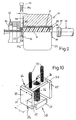
- Fig. 10 shows a double shear knife 38 of width i 1
- the lifting rod 36 passes through a rectangular yoke plate 70 with play, which in turn is fixed to a lifting rod 72 and carries a stop or spacer plate 74 of width m on both ends; the latter is slightly larger than the width i 1 of the double shear knife 38.
- This spacing device 76 comprising the yoke plate 70, the lifting rod 72 and the spacer plate 74 is lowered into the gap 40 between the sensor 18 and the die 32 in order to determine their effective distance n from one another, their being the Press direction x traversing longitudinal edges 75 stops.
- Distance device 76 and double shear knife 38 can be moved up and down separately from one another by drives, not shown.
- a channel profile 78 which is open at both ends, also serves as a positioning stop for defining that distance n or the gap width of the gap 40, which is inserted, for example, from the side.
- the channel profile 78 determines the mentioned gap width n with the cross-sectional length m of its legs 79.
- the legs 79 flank the pressing rest 42, which then stands in the profile interior or channel space 82, which is on the other hand delimited by the profile base 80.
- a flat indentation or recess 84 of a depth c of approximately 10 mm to 15 mm for the face plate 48 is formed in the profile base 80 toward the transducer 18.
- the indentation 84 is open towards the shear blade 39 so that it can be lowered onto the end plate 48 through the access 86 designed as an edge slot.
- the profile interior 82 at 88 is also equipped with an access for the - other - shear blade 39 a . Both entrances 86, 88 lie opposite one another on the upward-pointing longitudinal edges 90 of the channel profile 78.
- the die 32 according to the exemplary embodiment in FIG. 13 is preceded in the pressing direction x by a tool plate 52 of axis length b of 270 mm with a prechamber 54; in this the ductile ingot material is fed to the slit-like shape cross section 31, the horizontal longitudinal extension q of which, for example 750 mm, is considerably larger than the bore diameter d 1 of 520 mm.
- the shape cross section 31 widens on both sides to 280 mm as the longest height z 1 .
- the latter is determined in FIG. 14 by the two intersections of the longitudinal contours 31 a of the shape cross section 31 with the contour 22 a of the recipient bore 22. Outside of this, the end contour 31 e of the shape cross section 31 is part-circular.
- the lateral contour 56 of the chamber wall 58 is, according to FIG. 15, a straight line connecting the contour 22 a of the recipient bore 22, which delimits the base contour 56 b , which is curved in part-circular fashion, and the ridge contour 56 f which is curved in opposite directions 16 a funnel tapering towards the shape cross section 31.
- the three-dimensional shape of the chamber wall 58 is clear from an envelope surface 60 shown in FIG. 17.
Abstract
Description
Die Erfindung betrifft ein Verfahren zum Strangpressen eines Profils od.dgl. Körpers aus einem Barren, der in einer Rezipientenbohrung eines Aufnehmers geführt und mittels eines Preßstempels in Preßrichtung einem Formquerschnitt eines Formwerkzeuges zugeführt wird. Zudem erfaßt die Erfindung eine dafür besonders geeignete Vorrichtung.The invention relates to a method for extruding a profile or the like. Body from an ingot, which is guided in a recipient bore of a transducer and is fed to a mold cross section of a mold in the pressing direction by means of a press ram. In addition, the invention relates to a particularly suitable device.
Beim Strangpressen wird der duktil gewordene Werkstoff eines -- im Metallbereich etwa aus Bunt-, Sintermetallen oder Stahl, aber insbesondere aus einer Aluminiumlegierung vorgeformten -- erwärmten Gußbarrens oder Walzstababschnittes von einem Stempel -- oder beim hydrostatischen Strangpressen mittels einer Flüssigkeit -- durch einen oder mehrere Formquerschnitt/e eines die Preßrichtung querenden Formwerkzeuges gepreßt. Beim direkten oder Vorwärtsstrangpressen bewegt sich der Stempel in Richtung des Ablaufes des entstehenden Profils auf den Formquerschnitt zu, beim indirekten oder Rückwärts-Strangpressen wird der Werkstoff gegen die Stempelrichtung durch ein Werkzeug gedrückt, das am hohlen Stempel festgelegt ist.In extrusion, the material that has become ductile is a heated ingot or rolled rod section - in the metal sector, for example made of non-ferrous metals, sintered metals or steel, but in particular made of an aluminum alloy - from a stamp - or in hydrostatic extrusion by means of a liquid - by or several mold cross section / s of a molding tool crossing the pressing direction. With direct or forward extrusion, the stamp moves towards the shape of the profile in the direction of the profile that emerges, with indirect or reverse extrusion, the material is pressed against the direction of the stamp by a tool that is attached to the hollow stamp.
Ist beispielsweise beim direkten Strangpressen die Stirn des Stempels in Preßrichtung an das Formwerkzeug herangekommen, so verbleibt zwischen beiden an der hinteren Werkzeugfläche ein sog. Preßrest des verpreßten Barrens als mehr oder minder scheibenartiges Gebilde. Dieses wird üblicherweise durch ein radial am Werkzeug bewegtes Schermesser entfernt, bevor der nachfolgende Barren -- von dem inzwischen zurückgefahrenen Stempel im Aufnehmer verschoben -- an jene Werkzeugfläche schlägt und der eigentliche Formvorgang fortgesetzt werden kann.If, for example, in direct extrusion, the forehead of the punch has reached the molding tool in the pressing direction, a so-called pressing residue of the pressed ingot remains as a more or less disk-like structure between the two on the rear tool surface. This is usually removed by a shearing knife moved radially on the tool before the subsequent ingot - moved by the punch that has now moved back in the pick-up - strikes that tool surface and the actual molding process can be continued.
Metallbarren, insbesondere solche aus Aluminiumlegierungen, sind mit Verunreinigung -- beispielsweise Schmierstoffresten -- sowie mit einer Oxidschicht überzogen. Vor allem die Oxidpartikel an der Barrenstirn haben sich als äußerst schädlich für das Gefüge des entstehenden Profils erwiesen; die durch sie entstehende Zone mit verunreinigenden Einschlüssen ist -- in Abhängigkeit von Profilform und Preßgeschwindigkeit -- verhältnismäßig lang und zwingt bei zunehmenden Qualitätsanforderungen dazu, immer längere Profilabschnitte als Abfall aus dem entstehenden Strang herauszunehmen - mit allen sich daraus ergebenden Folgen abnehmender Wirtschaftlichkeit bei schrumpfendem Profilausstoß. Zahlreiche Versuche, diese Mängel zu beseitigen, blieben erfolglos.Metal bars, especially those made of aluminum alloys, are coated with impurities - for example lubricant residues - and with an oxide layer. In particular, the oxide particles on the forehead have proven to be extremely harmful to the structure of the resulting profile; the resulting zone with contaminating inclusions - depending on the profile shape and pressing speed - is relatively long and, with increasing quality requirements, forces longer and longer profile sections to be taken out of the resulting strand as waste - with all the resulting consequences of decreasing profitability and shrinking profile output . Numerous attempts to remedy these shortcomings have been unsuccessful.
In Kenntnis dieser Gegebenheiten hat sich der Erfinder das Ziel gesetzt, die beim Strangpressen insbesondere von Aluminiumlegierungen auftretenden Verunreinigungsbereiche am Übergang zweier benachbarter Blöcke oder Barren zu unterbinden.Knowing these circumstances, the inventor has set himself the goal of preventing the contamination areas occurring during the extrusion, in particular of aluminum alloys, at the transition between two adjacent blocks or ingots.
Zur Lösung dieser Aufgabe führt die Lehre der unabhängigen Patentansprüche; die Unteransprüche geben günstige Ausgestaltungen an.The teaching of the independent claims leads to solving this problem; the subclaims indicate favorable configurations.
Erfindungsgemäß wird vor Eintritt des vorderen Barrenendes in den Formquerschnitt zuerst dieser Barren angestaucht und in Preßrichtung um ein geringes Kragmaß -- von beispielsweise 10 mm -- aus dem Aufnehmer geschoben, wonach ein dabei entstehender scheibenartiger Abschnitt jenes freien Barrenendes abgeschert und entfernt sowie letzteres anschließend an den Formquerschnitt bzw. das hintere Ende des entstandenen Profils gebracht wird.According to the invention, before entering the front bar end into the mold cross-section, this bar is first compressed and pushed out of the transducer in the pressing direction by a small cantilever dimension - for example 10 mm, after which a resulting disk-like section is sheared off and removed from that free bar end and the latter is then attached the cross section of the shape or the rear end of the resulting profile is brought.
Durch das Entfernen dieses Frontabschnitts wird auch dessen Oxidhaut beseitigt, so daß -- ein schnelles Anschlagen der nun jungfräulichen Barrenstirn am Werkzeug vorausgesetzt -- Verunreinigungen durch Oxidpartikel dieser Barrenstirn ebensowenig befürchtet werden müssen wie das Entstehen längerer Abfallabschnitte in einem Profilstrang.By removing this front section, its oxide skin is also removed, so that - assuming a quick striking of the now virgin ingot forehead on the tool - contamination by oxide particles of this ingot end just as little to fear as the creation of longer waste sections in a profile strand.
Um die Zeit zwischen Schervorgang und Beginn des Weiterpressens zu vermeiden, soll das Entfernen der Barrenstirn bevorzugt zeitgleich mit dem üblichen Abscheren des Preßrestes vom Werkzeug erfolgen. Hierzu sollen letzteres und der Aufnehmer am Ende eines Preßvorganges axial relativ voneinander weg bewegt werden; sind ihre benachbarten Stirnflächen zueinander fixiert, kann der Schervorgang für Preßrest und Barren beginnen.In order to avoid the time between the shearing process and the start of further pressing, the removal of the ingot end should preferably take place at the same time as the usual shearing off of the pressing residue from the tool. For this purpose, the latter and the transducer are to be moved axially relatively away from one another at the end of a pressing operation; If their neighboring end faces are fixed to each other, the shearing process for the baling residue and bars can begin.
Von besonderer Bedeutung ist das erfindungsgemäße Abscheren der neuen Barrenstirn beim Herstellen eines Profils, dessen Querschnitt wenigstens teilweise größer ist als jener des Barrens selbst. Mittels der sog. Spreadertechnologie wird aus einem Barren geringen Durchmessers ein großes und breites Profil gepreßt, indem der Barrenwerkstoff in einer Vorkammer vor dem eigentlichen Formquerschnitt über den Querschnittsumriß des Barrens erweitert in vorbestimmten Bereichen gegebenenfalls innerhalb jenes Querschnittsumrisses auf einen engen Querschnitt verringert wird.Of particular importance is the shearing off of the new ingot end according to the invention when producing a profile, the cross section of which is at least partially larger than that of the ingot itself. By means of the so-called spreader technology, a large and broad profile is pressed from an ingot of small diameter by the ingot material in one Antechamber before the actual shape cross section extends over the cross section outline of the billet in predetermined areas, if necessary within that cross section outline, is reduced to a narrow cross section.
Die erfindungsgemäße Vorrichtung, mit der das beschriebene Verfahren durchgeführt werden kann, zeichnet sich dadurch aus, daß an der dem Formwerkzeug zugekehrten Rezipientenstirn des Aufnehmers ein Schermesser vorgesehen ist; dessen Scherklinge oder ein entsprechendes Trennorgan kann über die Mündung der Rezipientenbohrung geführt werden. Dazu ist die zeitweilige Fixierung des an sich axial bewegbaren Aufnehmers an der radialen Bewegungsbahn des Schermessers vorteilhaft.The device according to the invention, with which the described method can be carried out, is characterized in that a shear knife is provided on the recipient's end of the receiver facing the molding tool; its shear blade or a corresponding separating element can be guided over the mouth of the recipient bore. For this purpose, it is advantageous to temporarily fix the axially movable transducer to the radial movement path of the shear knife.
Wie bereits erwähnt, soll der Zeitraum zwischen dem Entfernen der werkzeugseitigen Barrenstirn sowie das Anschlagen der Schnittfläche am Ende des entstehenden Profils so kurz wie möglich gehalten werden. Um dies zu erreichen, soll der Abstand zwischen den benachbarten Stirnflächen von Aufnehmer einerseits und Formwerkzeug anderseits fixiert werden können; in den so entstehenden Spalt exakt vorbestimmter Weite wird dann ein Schermesser mit zwei Scherklingen eingefahren, die gleichzeitig den Preßrest des verarbeiteten Barrens am Werkzeug und die Barrenstirn des Folgebarrens entfernen. Diese Werkstoffscheiben können dann einem Schmelzprozeß zugeführt und -- in diesem Arbeitsgang von den schädlichen Oxidpartikeln befreit -- erneut der Produktion zugeleitet werden.As already mentioned, the period between the removal of the bar end on the tool side and the striking of the cut surface at the end of the resulting profile should be kept as short as possible. To achieve this, the distance between the adjacent end faces of the transducer on the one hand and mold on the other hand can be fixed; A shear knife with two shear blades is then inserted into the gap of exactly predetermined width, which at the same time removes the press residue of the processed ingot on the tool and the ingot end of the subsequent bar. These material disks can then be fed to a melting process and - freed from the harmful oxide particles in this operation - can be returned to production.
Nach einem weiteren Merkmal der Erfindung ist der Abstand der beiden Scherklingen des Schermessers einstellbar; so wird dessen Anpassung im Falle einer etwa durch Abtasten mit Laserstrahl festgestellten Abweichung der Spaltweite möglich.According to a further feature of the invention, the distance between the two shear blades of the shear knife is adjustable; this makes it possible to adapt it in the event of a deviation in the gap width, as found, for example, by scanning with a laser beam.
An der Rezipientenstirn können vorteilhafterweise Führungen für das Schermesser vorgesehen sein - dies vor allem dann, wenn von der Rezipientenstirn in an sich bekannter Weise ein ringförmiger Mündungsabschnitt einer im Aufnehmer ruhenden Rezipientenbüchse abragt.Guides for the shear knife can advantageously be provided on the recipient's forehead - especially when an annular mouth section of a recipient's sleeve resting in the receiver protrudes from the recipient's forehead in a manner known per se.
Als weitergehende Verbesserung ist anzusehen, dem Spalt zwischen Formwerkzeug und Aufnehmer eine quer zur Preßrichtung in den Spalt einfahrbare sowie rückstellbare Distanzeinrichtung zuzuordnen, an die Formwerkzeug und Aufnehmer anlegbar sind. Damit soll eine schnelle und problemlose Fixierung der Paarung Aufnehmer/Formwerkzeug zueinander erfolgen können.A further improvement is to be assigned to the gap between the molding tool and the transducer a spacer device which can be moved into the gap transversely to the pressing direction and can be reset, to which the molding tool and the transducer can be placed. This should allow for a quick and easy fixation of the pairing of the transducer / mold to one another.
Eine bevorzugte Ausführung der Distanzeinrichtung ist mit wenigstens einer in Preßrichtung verlaufenden Anschlagplatte od. dgl. Einsatz versehen, deren/dessen quer zur Preßrichtung angeordnete Kanten Anschläge für das Formwerkzeug und den Aufnehmer bilden. Insbesondere sollen zwei Anschlagplatten durch zumindest eine Jochplatte verbunden und mit dieser an ein bewegbares Gestänge od. dgl. Antriebseinrichtung angeschlossen sein, wobei dann die Anschlagplatten die Trenneinrichtung/en flankieren.A preferred embodiment of the spacer device is provided with at least one stop plate or the like running in the pressing direction, the edges of which are arranged transversely to the pressing direction and form stops for the molding tool and the receiver. In particular, two stop plates should be connected by at least one yoke plate and connected to a movable linkage or the like. Drive device, with the stop plates then flanking the separating device (s).
Diese Distanzeinrichtung ist gegenüber der Trenneinrichtung gesondert zu bewegen und wird vor ihr in den Spalt zwischen Aufnehmer und Formwerkzeug eingeführt, wonach der Aufnehmer an die Anschlagplatte/n herangefahren wird, bis diese anderseits dem Formwerkzeug anliegen. Einer mechanisch und manipulatorisch aufwendigen Verriegelung des Aufnehmers bedarf es so nicht mehr.This spacing device is to be moved separately from the separating device and is inserted in front of it into the gap between the transducer and the molding tool, after which the transducer is moved up to the stop plate (s) until they rest on the molding tool. A mechanically and manipulatively complex locking of the transducer is no longer required.
Ist eine aus der Voranmeldung bekannte Trenneinrichtung mit zwei in Abstand zueinander verlaufenden Scherklingen vorgesehen, so entspricht die Breite der Anschlagplatten etwa der Breite der die beiden Scherklingen enthaltenden Trenneinrichtung, d. h. letztere ist um beispielsweise 1 mm schmaler als jene Anschlagplatte/n, um ausreichend Spiel für die Scherklingen bzw. den Schervorgang zu haben; Distanzeinrichtung und Trenneinrichtung sind voneinander unabhängig zu bewegen, da sich letztere zum Abscheren in der dann stationären Distanzeinrichtung unbehindert verfahren werden soll.If a separating device known from the previous application is provided with two shaving blades running at a distance from one another, the width of the stop plates corresponds approximately to the width of the separating device containing the two shaving blades, i. H. the latter is, for example, 1 mm narrower than that stop plate (s) in order to have sufficient play for the shaving blades or the shearing process; The spacing device and separating device are to be moved independently of one another, since the latter is to be moved freely in the then stationary spacing device for shearing off.
Diese Unabhängigkeit der Trenneinrichtung von der Distanzeinrichtung gilt auch für eine andere Ausgestaltung letzterer; diese ist als -- zumindest einends offenes -- Rinnenprofil ausgebildet, dessen Schenkel einerseits sowie dessen Rinnenboden anderseits Anschläge für das Formwerkzeug und den Aufnehmer bilden, wobei die Schenkel querschnittlich parallel zur Preßrichtung verlaufen und in Betriebs- oder Scherstellung beidseits des Preßrestes stehen; in dieser Betriebsstellung der Anordnung Aufnehmer-Rinnenprofil-Formwerkzeug befindet sich vor dem Abscheren der -- nicht immer ganz flache -- Preßrest vorteilhafterweise im Profilinnenraum, so daß die Außenfläche des Rinnenbodens dem Bolzen bzw. dessen Stirnscheibe zugekehrt ist.This independence of the separation device from the distance device also applies to another embodiment of the latter; this is designed as a - at least one end open - channel profile, the legs of which on the one hand and the channel bottom on the other form stops for the molding tool and the receiver, the legs running cross-sectionally parallel to the pressing direction and in the operating or shear position on both sides of the pressing residue; in this operating position of the arrangement of the receiver-channel profile molding tool, the - not always completely flat - pressing residue is advantageously in the interior of the profile before shearing off, so that the outer surface of the channel bottom faces the bolt or its end plate.
So hat es sich als günstig erwiesen, im Rinnenboden außenseitig eine Einformung zur Aufnahme der in Preßrichtung weisenden Stirnscheibe des Barrens vorzusehen. Üblicherweise genügt für diese Einformung eine Tiefe von etwa 10 mm.It has proven to be advantageous to provide an indentation on the outside in the channel bottom for receiving the end plate of the ingot pointing in the pressing direction. A depth of approximately 10 mm is usually sufficient for this indentation.
Um das Einführen der Scherklingen in den Profilinnenraum und die Einformung zu ermöglichen, ist diesen jeweils ein Durchlaß für eine Scherklinge der Trenneinrichtung zugeordnet, und beide Durchlässe liegen einander an Längskanten des Rinnenprofils gegenüber, sind also zueinander gleich gerichtet.In order to enable the shear blades to be inserted into the profile interior and to be shaped in, a passage for a shear blade of the separating device is assigned to each of them, and both passages lie opposite one another on the longitudinal edges of the channel profile, that is to say they are directed in the same direction to one another.
Bei der Trenneinrichtung mit zwei in Abstand zueinander verlaufenden Scherklingen sind diese von unterschiedlicher Länge, um das Eintauchen in Preßrest und Stirnscheibe zeitlich zu versetzen. Dazu soll bevorzugt die dem Formwerkzeug zugeordnete Scherklinge länger sein als die dem Aufnehmer nahe Scherklinge.In the separating device with two shear blades running at a distance from one another, these are of different lengths in order to offset the time immersed in the pressing residue and end plate. For this purpose, the shear blade assigned to the molding tool should preferably be longer than the shear blade close to the pickup.
Die dem Werkzeug in Preßrichtung vorgeordnete Vorkammer zum Verpressen eines Aluminiumblockes mit dessen sog. Spreadern erweitert sich erfindungsgemäß vom Durchmesser der Rezipientenbohrung weg zum Formquerschnitt hin in zumindest einer in Preßrichtung verlaufenden Ebene, die von einer diese Preßrichtung querenden Achse bestimmt wird.The pre-chamber upstream of the tool in the pressing direction for pressing an aluminum block with its so-called spreader expands according to the invention away from the diameter of the recipient bore towards the mold cross section in at least one plane running in the pressing direction, which is determined by an axis crossing this pressing direction.
Bei einer Ausführung dieser Vorkammer verjüngt sich deren Querschnitt in Preßrichtung beidseits einer anderen Achse, welche die vorstehend genannte kreuzt. In diesem Bereich vermindert sich also der Materialbedarf beim Pressen gegenüber dem Angebot des Barrens; das hier überschüssige Material wird zur anderen Achse gelenkt.In an embodiment of this prechamber, its cross section tapers in the pressing direction on both sides of another axis which crosses the aforementioned. In this area, therefore, the material requirement for pressing is reduced compared to the bar supply; the excess material here is directed to the other axis.
Als besonders günstig hat es sich erwiesen, die beiden Achsen zueinander rechtwinkelig zu stellen und als Symmetrielinien einzusetzen; hierdurch wird die erörterte Materialverteilung vergleichmäßigt.It has proven to be particularly advantageous to place the two axes at right angles to one another and to use them as lines of symmetry; this makes the material distribution discussed more uniform.
Weitere Vorteile, Merkmale und Einzelheiten der Erfindung ergeben sich aus der nachfolgenden Beschreibung bevorzugter Ausführungsbeispiele sowie anhand der Zeichnung; diese zeigt in
- Fig. 1:
- eine Schrägsicht auf einen Teil einer Strangpresse mit einem horizontal verlaufenden Preßstempel;
- Fig. 2:
- einen vergrößerten Ausschnitt aus Fig. 1;
- Fig. 3:
- einen Längsschnitt durch einen skizzenhaft dargestellten Aufnehmer der Strangpresse mit in Preßrichtung in Abstand vorgeordnetem Preßstempel und nachfolgendem Formwerkzeug;
- Fig. 4, 5:
- der Fig. 3 entsprechende Darstellungen unterschiedlicher Stellungen von Aufnehmer und Preßstempel;
- Fig. 6,8,9:
- unterschiedliche Ausführungen von zwischen Aufnehmer und Formwerkzeug angeordneten Trenneinrichtungen;
- Fig. 7:
- die Trenneinrichtung der Fig. 8 in vergrößerter Seitenansicht;
- Fig. 10:
- eine Schrägsicht auf ein Doppelschermesser mit Distanzhalterung für Aufnehmer und Formwerkzeug;
- Fig. 11:
- eine der Fig. 8 entsprechende Darstellung von Aufnehmer und Formwerkzeug mit einer anderen dazwischen angeordneter Distanzhalterung;
- Fig. 12:
- die Distanzhalterung der Fig. 11 in vergrößerter Schrägsicht;
- Fig. 13:
- einen Teil einer vergrößerten Seitenansicht eines Werkzeuges mit Vorkammer für das Strangpressen nach der sog. Spreadertechnologie;
- Fig. 14:
- eine Skizze zu der in Preßrichtung gesehenen Vorkammer samt Formquerschnitt;
- Fig. 15,16:
- Querschnitte durch die Vorkammer gemäß Linie Q bzw. Linie M in Fig. 14;
- Fig. 17:
- skizzenhaft die theoretische Hüllfläche für den Materialfluß im Werkzeug.
- Fig. 1:
- an oblique view of part of an extrusion press with a horizontally extending ram;
- Fig. 2:
- an enlarged section of Fig. 1;
- Fig. 3:
- a longitudinal section through a sketchy pick-up of the extrusion press with a pre-arranged in the pressing direction at a distance ram and subsequent mold;
- 4, 5:
- 3 corresponding representations of different positions of the transducer and ram;
- 6,8,9:
- different designs of separating devices arranged between the transducer and the mold;
- Fig. 7:
- 8 in an enlarged side view;
- Fig. 10:
- an oblique view of a double shear knife with a spacer for the transducer and mold;
- Fig. 11:
- a representation corresponding to Figure 8 of the transducer and mold with another spacer arranged in between.
- Fig. 12:
- the spacer of Figure 11 in an enlarged oblique view.
- Fig. 13:
- a part of an enlarged side view of a tool with pre-chamber for extrusion according to the so-called spreader technology;
- Fig. 14:
- a sketch of the prechamber seen in the pressing direction together with the shape cross section;
- Fig. 15, 16:
- Cross sections through the prechamber according to line Q or line M in Fig. 14;
- Fig. 17:
- sketchy the theoretical envelope surface for the material flow in the tool.
Eine Strangpresse 10 zum direkten Strangpressen von Profilen 12 weist gemäß Fig. 1 an einem Preßzylinder 14 einen Preßstempel 16 auf, der in der Längsachse A einer einen Rezipienten oder Aufnehmer 18 durchsetzenden Bohrung 19 verläuft. Der Durchmesser d einer Preßscheibe 17 an der freien Stirnfläche des Preßstempels 16 ist geringfügig kürzer als der freie Bohrungsdurchmesser d1, so daß der Preßstempel 16 in die sog. Rezipientenbohrung einzutauchen vermag. Der erwähnte freie Bohrungsdurchmesser d1 wird von der Innenfläche 20 einer in den Aufnehmer 18 bzw. dessen Bohrung 19 eingesetzten Rezipientenbüchse 21 begrenzt. Folgend wird der Innenraum dieser Rezipientenbüchse 21 als Rezipientenbohrung 22 bezeichnet.An
Der maximale Abstand zwischen einer stempelseitigen Rezipientenfront 23 und der Preßscheibe 17 in -- nicht dargestellter -- Ruhelage des Preßstempels 16 ist so bemessen, daß der Rezipientenbohrung 22 ein bei 24 angedeuteter Block oder Barren aus Leichtmetall, insbesondere aus einer vorgewärmten Aluminiumlegierung, durch einen Ladeschlitten 26 vorgesetzt und vom Preßstempel 16 in Preßrichtung x in die Rezipientenbohrung 22 eingeschoben werden kann.The maximum distance between a die-
Nahe einer dem Preßstempel 16 fernliegenden Rezipientenstirn 23a ruht in einem Matrizenhalter 28 an einem Querhaupt 30 eine Matrize als Formwerkzeug 32. Dieser folgt in Preßrichtung x ein Austragskanal 34 des Querhauptes 30, durch den das in einem Formquerschnitt 31 der Matrize 32 entstehende Profil 12 entfernt wird.In the
Oberhalb der Rezipientenstirn 23a ist in Fig. 1 eine Hubeinrichtung 36 für ein Schermesser 38 zu erkennen, das radial zu einem Spalt 40 zwischen Aufnehmer 18 und Formwerkzeug 32 bewegbar vorgesehen ist.A lifting
In der in Fig. 2 skizzierten Betriebsstellung am Ende eines Preßvorgangs findet sich am stempelfernen Ende der Rezipientenbohrung 22 an der dieser zugekehrten Werkzeugfläche 33 ein sog. Preßrest 42, von dem sich die Preßscheibe 17 entfernt hat. Die Werkzeugfläche 33 bleibt dank eines vom Überstand der Rezipientenbüchse 21 gebildeten Mündungskragens 44 in Abstand zur Rezipientenstirn 23a. Auch an der hinteren Rezipientenfront 23 umgibt die Rezipientenbohrung 22 ein Ringkragen 46 als Überstand der Rezipientenbüchse 21.In the operating position outlined in FIG. 2 at the end of a pressing process, a so-called
Beim Einschieben eines neuen Barrens 24 nähert sich das freie Barrenende dem Preßrest 42 einer beispielsweisen Dicke a von 80 mm. Der heckwärtige Barrenüberstand e beträgt höchstens 20 mm.When a
Nunmehr wird der Rezipient oder Aufnehmer 18 -- beispielsweise um mehr als 450 mm -- soweit zurückgefahren, bis der Preßrest 42 freisteht (Fig. 5). Ragt der Barren 24 gemäß Fig. 6 in einer Kraglänge t von etwa 10 mm über den Mündungskragen 44 hinaus, wird der Barren 24 mit dem Preßstempel 16 angestaucht; der Barren 24 soll bei einem noch zu beschreibenden nachfolgenden Schervorgang nicht durch das Schermesser 38 verschoben werden können.Now the recipient or
Vor dem Schervorgang wird der Aufnehmer 18 gegen die Preßrichtung x zurückgefahren, bis die hintere Werkzeugfläche 33 des Formwerkzeuges bzw. der Matrize 32 in einem Abstand n zur Rezipientenstirn 23a steht. In dieser Stellung werden Aufnehmer 18 und Matrize 32 zeitweilig fixiert.Before the shearing process, the
Durch Absenken zweier in Fig. 6 bei 39, 39a angedeuteter Scherklingen des Schermessers 38 werden gleichzeitig der Preßrest 42 und eine -- vom erwähnten Überstand der Kraglänge t des Barrens 24 bestimmte -- Stirnscheibe 48 des Barrens 24 -- und damit dessen in Preßrichtung x weisende Stirnfläche 49 -- entfernt; an der Barrenstirnfläche 49 hat sich vor den hier erörterten Vorgängen eine Oxidschicht gebildet, die in Fig. 8 mit 49a bezeichnet ist und deren Oxidpartikel bei Übernahme in das entstehende Profil 12 störende Verunreinigungen erzeugen würden.By lowering two
Um eine genaue Führung des Schermessers 38 zu gewährleisten, sind an der Rezipientenstirn 23a oberhalb des Mündungskragens 44 diesen schützende vertikale Führungsleisten 50 als Messerabweiser angebracht. Deren Tiefe entspricht der Höhe h des Mündungskragens 44 (Fig. 5).In order to ensure accurate guidance of the
Das bevorzugt aus einer dem Formwerkzeug 32 nahen Klingenplatte 37 und einem an dieser festliegenden Klingenwinkel 37a bestehende Doppelschermesser 38 bietet in Fig. 7,8 Scherklingen 39,39a unterschiedlicher Längen f,f1 an; die für den Preßrest 42 bestimmte Scherklinge 39a der Klingenplatte 37 ist länger als das dem Aufnehmer 18 zugeordnete Schabmesser 39. Letzteres gleitet in Fig. 8 an einer Abweiserleiste 50a entlang.The
Beim Ausführungsbeispiel der Fig. 9 bleiben Preßrest 42 und Barrenstirnfläche 49 einander eng benachbart, so daß die Breite i des Schermessers 38a sehr klein gehalten werden kann. Hierbei entsteht ein äußerst kurzer Weg zwischen der neuen -- durch Entfernen der Stirnscheibe 48 entstandenen - - oxidschichtfreien Barrenstirn und dem gleichzeitig vom Preßrest 42 befreiten Profilende.In the embodiment of FIG. 9, the
Nach dem Schervorgang wird der Aufnehmer 18 wieder an die Matrize bzw. das Formwerkzeug 32 gefahren - der Preßvorgang kann von neuem beginnen.After the shearing process, the
Fig. 10 zeigt ein Doppelschermesser 38 der Breite i1, dessen Hubstange 36 eine rechteckige Jochplatte 70 mit Spiel durchsetzt, die ihrerseits an einem Hubgestänge 72 festliegt und beidends jeweils eine Anschlag- oder Distanzplatte 74 der Breite m trägt; letztere ist geringfügig größer als die Breite i1 des Doppelschermessers 38. Diese Distanzeinrichtung 76 aus Jochplatte 70, Hubgestänge 72 und Distanzplatte 74 wird in den Spalt 40 zwischen Aufnehmer 18 und Matrize 32 abgesenkt, um deren wirksamen Abstand n voneinander zu bestimmen, wobei ihre die Preßrichtung x querenden Längskanten 75 Anschläge bilden. Distanzeinrichtung 76 und Doppelschermesser 38 sind durch nicht dargestellte Antriebe voneinander getrennt auf- und abbewegbar.Fig. 10 shows a
Ebenfalls zum Festlegen jenes Abstandes n bzw. der Spaltweite des Spaltes 40 dient ein beidends offenes Rinnenprofil 78 als Positionieranschlag, das beispielsweise von der Seite her eingeschoben wird. Das Rinnenprofil 78 bestimmt mit der Querschnittslänge m seiner Schenkel 79 die erwähnte Spaltweite n.A
Die Schenkel 79 flankieren in Betriebsstellung den Preßrest 42, der dann in dem -- anderseits vom Profilboden 80 begrenzten -- Profilinnen- oder Rinnenraum 82 steht. Zum Aufnehmer 18 hin ist in den Profilboden 80 eine flache Einformung oder Ausnehmung 84 einer Tiefe c von etwa 10 mm bis 15 mm für die Stirnscheibe 48 eingeformt. Die Einformung 84 ist zur Scherklinge 39 hin offen, damit diese durch den als Randschlitz ausgebildeten Zugang 86 auf die Stirnscheibe 48 abgesenkt werden kann. Auch der Profilinnenraum 82 ist bei 88 mit einem Zugang für die -- andere -- Scherklinge 39a ausgestattet. Beide Zugänge 86,88 liegen an den aufwärts weisenden Längskanten 90 des Rinnenprofils 78 einander gegenüber.In the operating position, the
Der Matrize 32 nach dem Ausführungsbeispiel der Fig. 13 ist in Preßrichtung x ein Werkzeugteller 52 der Achslänge b von 270 mm mit einer Vorkammer 54 vorgesetzt; in dieser wird das duktile Barrenmaterial dem hier schlitzartigen Formquerschnitt 31 zugeführt, dessen horizontale Längserstreckung q mit beispielsweise 750 mm erheblich größer ist als der Bohrungsdurchmesser d1 von 520 mm. Die Höhe z des Formquerschnitts 31 in dessen eine Mittelebene in Preßrichtung x bestimmender vertikaler Mittelachse M mißt lediglich 240 mm. Von der -- wie auch die Querachse Q einer Querachse zu ihr -- eine Symmetriegerade darstellenden Mittelachse M erweitert sich der Formquerschnitt 31 nach beiden Seiten auf 280 mm als längster Höhe z1. Letztere ist in Fig. 14 von den beiden Schnittpunkten der Längskonturen 31a des Formquerschnitts 31 mit der Kontur 22a der Rezipientenbohrung 22 bestimmt. Außerhalb deren ist die Endkontur 31e des Formquerschnitts 31 teilkreisförmig.The die 32 according to the exemplary embodiment in FIG. 13 is preceded in the pressing direction x by a
Die seitliche Kontur 56 der Kammerwandung 58 ist nach Fig. 15 eine die Kontur 22a der Rezipientenbohrung 22 verbindende Gerade, die teilkreisförmig gekrümmte Bodenkontur 56b und die gegenläufig gekrümmte Firstkontur 56f begrenzen gemäß Fig. 16 einen sich zum Formquerschnitt 31 hin verjüngenden Trichter. Die dreidimensionale Form der Kammerwandung 58 wird durch eine in Fig. 17 vorgestellte Hüllfläche 60 deutlich.The
Die Erzeugung von großen, breiten Profilen 12 aus einer verhältnismäßig engen Rezipientenbohrung 22 wird mittels der sog. Spreadertechnologie durchgeführt. Mit letzterer können für Rechteckrezipienten ausgelegte Werkzeuge 32 dank der Vorkammer 54 aus Rundrezipienten oder -aufnehmern 18 gefertigt werden.The generation of large,
Claims (24)
dadurch gekennzeichnet,
daß vor Eintritt des Barrens in den Formquerschnitt der Barren in Preßrichtung um ein Kragmaß aus dem Aufnehmer geschoben wird, wonach ein dabei entstehender scheibenartiger Abschnitt des freien Barrenendes abgeschert und entfernt sowie letzteres anschließend an den Formquerschnitt gebracht wird.Method for extruding a profile or the like Body from an ingot, which is guided in a recipient bore of a transducer and is fed to a mold cross section of a mold in the pressing direction by means of a press ram,
characterized,
that before the ingot enters the cross-section of the ingot, the ingot is pushed by a cantilever in the pressing direction, after which a disc-like section of the free end of the ingot which is formed is sheared off and removed, and the latter is subsequently brought to the cross-section of the form.
Applications Claiming Priority (2)
| Application Number | Priority Date | Filing Date | Title |
|---|---|---|---|
| DE19603853 | 1996-02-05 | ||
| DE19603853 | 1996-02-05 |
Publications (4)
| Publication Number | Publication Date |
|---|---|
| EP0787543A2 true EP0787543A2 (en) | 1997-08-06 |
| EP0787543A3 EP0787543A3 (en) | 1998-06-03 |
| EP0787543B1 EP0787543B1 (en) | 2001-12-12 |
| EP0787543B2 EP0787543B2 (en) | 2005-02-02 |
Family
ID=7784395
Family Applications (1)
| Application Number | Title | Priority Date | Filing Date |
|---|---|---|---|
| EP97810042A Expired - Lifetime EP0787543B2 (en) | 1996-02-05 | 1997-01-29 | Method for extruding profiles or the like from bars and device therefore |
Country Status (14)
| Country | Link |
|---|---|
| US (1) | US5836190A (en) |
| EP (1) | EP0787543B2 (en) |
| AT (1) | ATE210514T1 (en) |
| AU (1) | AU699911B2 (en) |
| CA (1) | CA2196372C (en) |
| CZ (1) | CZ291518B6 (en) |
| DE (1) | DE19605885C1 (en) |
| DK (1) | DK0787543T4 (en) |
| ES (1) | ES2165011T5 (en) |
| HU (1) | HU219838B (en) |
| NO (1) | NO312157B1 (en) |
| PL (1) | PL182822B1 (en) |
| PT (1) | PT787543E (en) |
| SK (1) | SK283676B6 (en) |
Cited By (2)
| Publication number | Priority date | Publication date | Assignee | Title |
|---|---|---|---|---|
| EP0987068A3 (en) * | 1998-09-16 | 2001-06-13 | Alusuisse Technology & Management AG | Method and device for the extrusion of a hollow section or similar body from bars |
| WO2009088525A1 (en) * | 2008-01-04 | 2009-07-16 | G. James Australia Pty. Ltd. | Method of welding heated log segments in an aluminum extrusion process |
Families Citing this family (8)
| Publication number | Priority date | Publication date | Assignee | Title |
|---|---|---|---|---|
| DE19703576C2 (en) * | 1996-02-19 | 2001-05-17 | Alusuisse Tech & Man Ag | Device for extruding a profile or the like body from an ingot |
| DE19842293C2 (en) * | 1998-09-16 | 2003-06-26 | Alcan Tech & Man Ag | Method for extruding a hollow profile or the like body from an ingot and device therefor |
| DE10141223C1 (en) * | 2001-07-11 | 2002-11-21 | Alusuisse Tech & Man Ag | Profile extrusion method, for ductile material such as solder material or aluminium alloy, uses direct forcing of ductile material bar through forming tool via displaced pressure die |
| WO2003006189A1 (en) * | 2001-07-11 | 2003-01-23 | Alcan Technology & Management Ltd. | Device for extruding a profile or a similar billet from a bolt or bar and corresponding device |
| DE10211267A1 (en) * | 2002-03-13 | 2003-09-25 | Sms Eumuco Gmbh | Operating a metal strand press having a block feeder comprises cutting off a front piece of the end of the block, which faces the matrix, before the block is inserted into the block feeder |
| CN101522328B (en) * | 2006-10-16 | 2011-08-31 | 宇部兴产机械株式会社 | Stem slide device |
| JP5468602B2 (en) | 2009-04-20 | 2014-04-09 | 昭和電工株式会社 | Extrusion processing method and extrusion processing apparatus |
| IT201700115300A1 (en) * | 2017-10-12 | 2019-04-12 | Davide Turla | Extrusion press with direct mechanical actuation. |
Citations (5)
| Publication number | Priority date | Publication date | Assignee | Title |
|---|---|---|---|---|
| DE1076064B (en) * | 1958-01-14 | 1960-02-25 | Hydraulik Gmbh | Metal extrusion press with device for separating the extrusion from the extrusion residue |
| FR1229992A (en) * | 1959-03-27 | 1960-09-12 | Cefilac | Method and device for cutting hot-spun metal products |
| DE3003311A1 (en) * | 1979-01-31 | 1980-08-07 | Secim | CUTTING DEVICE FOR A PRESS FOR DIRECTLY EXPRESSING METAL PRESSING BOLTS |
| JPH05131214A (en) * | 1991-11-08 | 1993-05-28 | Showa Alum Corp | Extrusion machining device |
| JPH0671334A (en) * | 1992-08-25 | 1994-03-15 | Ube Ind Ltd | Indirect extrusion press use as also direct extrusion press |
Family Cites Families (5)
| Publication number | Priority date | Publication date | Assignee | Title |
|---|---|---|---|---|
| DE2651564C2 (en) * | 1976-11-11 | 1982-12-16 | Aluminium-Walzwerke Singen Gmbh, 7700 Singen | Device on an extrusion press for peeling the metal blocks |
| JPS57154313A (en) * | 1981-03-20 | 1982-09-24 | Nippon Light Metal Co Ltd | Extruding method of metal |
| US4793170A (en) * | 1987-06-19 | 1988-12-27 | Everett Daniels | Shear blade for aluminum extrusion process |
| JPH04251610A (en) * | 1991-01-24 | 1992-09-08 | Showa Alum Corp | Method for preventing material from leaking in extrusion of metallic material to be formed |
| JP2920910B2 (en) * | 1992-03-17 | 1999-07-19 | 宇部興産株式会社 | Method and apparatus for separating dies and products of indirect extrusion press |
-
1996
- 1996-02-19 DE DE19605885A patent/DE19605885C1/en not_active Expired - Fee Related
-
1997
- 1997-01-06 US US08/778,951 patent/US5836190A/en not_active Expired - Fee Related
- 1997-01-14 HU HU9700117A patent/HU219838B/en not_active IP Right Cessation
- 1997-01-27 CZ CZ1997236A patent/CZ291518B6/en not_active IP Right Cessation
- 1997-01-29 EP EP97810042A patent/EP0787543B2/en not_active Expired - Lifetime
- 1997-01-29 ES ES97810042T patent/ES2165011T5/en not_active Expired - Lifetime
- 1997-01-29 PT PT97810042T patent/PT787543E/en unknown
- 1997-01-29 AT AT97810042T patent/ATE210514T1/en not_active IP Right Cessation
- 1997-01-29 DK DK97810042T patent/DK0787543T4/en active
- 1997-01-30 AU AU12405/97A patent/AU699911B2/en not_active Ceased
- 1997-01-30 CA CA002196372A patent/CA2196372C/en not_active Expired - Fee Related
- 1997-02-03 NO NO19970461A patent/NO312157B1/en unknown
- 1997-02-04 PL PL97318276A patent/PL182822B1/en not_active IP Right Cessation
- 1997-02-05 SK SK163-97A patent/SK283676B6/en unknown
Patent Citations (5)
| Publication number | Priority date | Publication date | Assignee | Title |
|---|---|---|---|---|
| DE1076064B (en) * | 1958-01-14 | 1960-02-25 | Hydraulik Gmbh | Metal extrusion press with device for separating the extrusion from the extrusion residue |
| FR1229992A (en) * | 1959-03-27 | 1960-09-12 | Cefilac | Method and device for cutting hot-spun metal products |
| DE3003311A1 (en) * | 1979-01-31 | 1980-08-07 | Secim | CUTTING DEVICE FOR A PRESS FOR DIRECTLY EXPRESSING METAL PRESSING BOLTS |
| JPH05131214A (en) * | 1991-11-08 | 1993-05-28 | Showa Alum Corp | Extrusion machining device |
| JPH0671334A (en) * | 1992-08-25 | 1994-03-15 | Ube Ind Ltd | Indirect extrusion press use as also direct extrusion press |
Non-Patent Citations (2)
| Title |
|---|
| PATENT ABSTRACTS OF JAPAN vol. 017, no. 503 (M-1478), 10.September 1993 & JP 05 131214 A (SHOWA ALUM CORP), 28.Mai 1993, * |
| PATENT ABSTRACTS OF JAPAN vol. 018, no. 314 (M-1621), 15.Juni 1994 & JP 06 071334 A (UBE IND LTD), 15.März 1994, * |
Cited By (6)
| Publication number | Priority date | Publication date | Assignee | Title |
|---|---|---|---|---|
| EP0987068A3 (en) * | 1998-09-16 | 2001-06-13 | Alusuisse Technology & Management AG | Method and device for the extrusion of a hollow section or similar body from bars |
| WO2009088525A1 (en) * | 2008-01-04 | 2009-07-16 | G. James Australia Pty. Ltd. | Method of welding heated log segments in an aluminum extrusion process |
| US7712651B2 (en) | 2008-01-04 | 2010-05-11 | G. James Australia Pty. Ltd. | Method of welding heated log segments in an aluminum extrusion process |
| US7950566B2 (en) | 2008-01-04 | 2011-05-31 | G. James Australia Pty. Ltd. | Method of welding heated log segments in an aluminum extrusion process |
| EP2384831A1 (en) * | 2008-01-04 | 2011-11-09 | G. James Australia Pty. Ltd. | Method of welding heated log segments in an aluminum extrusion process |
| CN101918156B (en) * | 2008-01-04 | 2013-08-21 | G·詹姆斯澳大利亚股份有限公司 | Method of welding heated log segments in an aluminum extrusion process |
Also Published As
| Publication number | Publication date |
|---|---|
| US5836190A (en) | 1998-11-17 |
| HU219838B (en) | 2001-08-28 |
| DE19605885C1 (en) | 1997-08-21 |
| CZ23697A3 (en) | 1997-12-17 |
| CA2196372C (en) | 2003-03-18 |
| HUP9700117A2 (en) | 1997-08-28 |
| EP0787543A3 (en) | 1998-06-03 |
| AU1240597A (en) | 1997-08-14 |
| EP0787543B1 (en) | 2001-12-12 |
| SK16397A3 (en) | 1997-09-10 |
| PL318276A1 (en) | 1997-08-18 |
| EP0787543B2 (en) | 2005-02-02 |
| CA2196372A1 (en) | 1997-08-06 |
| NO970461L (en) | 1997-08-06 |
| ES2165011T3 (en) | 2002-03-01 |
| ATE210514T1 (en) | 2001-12-15 |
| NO312157B1 (en) | 2002-04-02 |
| PL182822B1 (en) | 2002-03-29 |
| ES2165011T5 (en) | 2005-06-16 |
| HU9700117D0 (en) | 1997-02-28 |
| DK0787543T4 (en) | 2005-06-06 |
| PT787543E (en) | 2002-05-31 |
| CZ291518B6 (en) | 2003-03-12 |
| NO970461D0 (en) | 1997-02-03 |
| DK0787543T3 (en) | 2002-04-15 |
| AU699911B2 (en) | 1998-12-17 |
| SK283676B6 (en) | 2003-11-04 |
| HUP9700117A3 (en) | 2000-03-28 |
Similar Documents
| Publication | Publication Date | Title |
|---|---|---|
| DE2651564A1 (en) | DEVICE FOR PRESSING WORK PIECES FROM A BLOCK | |
| EP0463201A1 (en) | Continuous casting plant for steel containing a mechanical removal installation for oxygen-cutting burrs | |
| EP0787543B1 (en) | Method for extruding profiles or the like from bars and device therefore | |
| DE10141223C1 (en) | Profile extrusion method, for ductile material such as solder material or aluminium alloy, uses direct forcing of ductile material bar through forming tool via displaced pressure die | |
| WO1986003440A1 (en) | Method and device for cutting pipe lengths | |
| DE10231328B4 (en) | Extrusion press and extrusion press process | |
| EP0374950B1 (en) | Method and devices for applying a hard material in the molten state to cutting tool teeth | |
| EP0037485A1 (en) | Metal extrusion press comprising a device mounted at the container for separating the extrusion butt and exchanging the dies | |
| DE19703576C2 (en) | Device for extruding a profile or the like body from an ingot | |
| EP0987068B1 (en) | Method and device for the extrusion of a hollow section or similar body from bars | |
| DE4128677A1 (en) | Lying metal extrusion press | |
| DE1303557B (en) | Method and device for producing an electrical contact element | |
| DE102004057677B4 (en) | Sprue device for injection molds | |
| DE19842293C2 (en) | Method for extruding a hollow profile or the like body from an ingot and device therefor | |
| DE102018003622A1 (en) | Device and method for cutting out a workpiece | |
| DE2238607A1 (en) | METHOD AND DEVICE FOR THE MACHINING OF PROFILES FOR TURBINE BLADE FOOT | |
| DE10145877C1 (en) | Method for extruding a hollow profile or the like body from an ingot and device therefor | |
| DE2942001A1 (en) | MACHINE FOR MAKING SCREWS OR THE LIKE | |
| EP1423217A1 (en) | Method for the extrusion of a hollow profile or similar body from a bar and corresponding device | |
| DE3527864A1 (en) | METHOD FOR EXTRUDING OR PULLING | |
| DE3402609C2 (en) | Device for producing a drawing lever at the beginning of Cu or Al flat material | |
| WO2003006189A1 (en) | Device for extruding a profile or a similar billet from a bolt or bar and corresponding device | |
| DD230806A1 (en) | METHOD AND TOOL FOR DISCONNECTING PROFILE STATIONS | |
| EP3446807A1 (en) | Method for the production of a blind hole | |
| DE2708586A1 (en) | PROCESS FOR INDIRECT EXTRUSION AND DEVICE FOR CARRYING OUT THE PROCESS |
Legal Events
| Date | Code | Title | Description |
|---|---|---|---|
| PUAI | Public reference made under article 153(3) epc to a published international application that has entered the european phase |
Free format text: ORIGINAL CODE: 0009012 |
|
| AK | Designated contracting states |
Kind code of ref document: A2 Designated state(s): AT BE CH DK ES FI FR GB GR IE IT LI LU NL PT SE |
|
| PUAL | Search report despatched |
Free format text: ORIGINAL CODE: 0009013 |
|
| AK | Designated contracting states |
Kind code of ref document: A3 Designated state(s): AT BE CH DE DK ES FI FR GB GR IE IT LI LU MC NL PT SE |
|
| 17P | Request for examination filed |
Effective date: 19981203 |
|
| 17Q | First examination report despatched |
Effective date: 19991115 |
|
| GRAG | Despatch of communication of intention to grant |
Free format text: ORIGINAL CODE: EPIDOS AGRA |
|
| GRAG | Despatch of communication of intention to grant |
Free format text: ORIGINAL CODE: EPIDOS AGRA |
|
| GRAH | Despatch of communication of intention to grant a patent |
Free format text: ORIGINAL CODE: EPIDOS IGRA |
|
| RBV | Designated contracting states (corrected) |
Designated state(s): AT BE CH DK ES FI FR GB GR IE IT LI LU NL PT SE |
|
| GRAH | Despatch of communication of intention to grant a patent |
Free format text: ORIGINAL CODE: EPIDOS IGRA |
|
| REG | Reference to a national code |
Ref country code: DE Ref legal event code: 8566 |
|
| GRAA | (expected) grant |
Free format text: ORIGINAL CODE: 0009210 |
|
| RAP1 | Party data changed (applicant data changed or rights of an application transferred) |
Owner name: ALCAN TECHNOLOGY & MANAGEMENT AG |
|
| AK | Designated contracting states |
Kind code of ref document: B1 Designated state(s): AT BE CH DK ES FI FR GB GR IE IT LI LU NL PT SE |
|
| REF | Corresponds to: |
Ref document number: 210514 Country of ref document: AT Date of ref document: 20011215 Kind code of ref document: T |
|
| RTI1 | Title (correction) |
Free format text: METHOD FOR EXTRUDING PROFILES OR THE LIKE FROM BARS AND DEVICE THEREFORE |
|
| REG | Reference to a national code |
Ref country code: CH Ref legal event code: EP |
|
| REG | Reference to a national code |
Ref country code: GB Ref legal event code: IF02 |
|
| REG | Reference to a national code |
Ref country code: IE Ref legal event code: FG4D Free format text: GERMAN |
|
| PGFP | Annual fee paid to national office [announced via postgrant information from national office to epo] |
Ref country code: LU Payment date: 20020129 Year of fee payment: 6 |
|
| REG | Reference to a national code |
Ref country code: ES Ref legal event code: FG2A Ref document number: 2165011 Country of ref document: ES Kind code of ref document: T3 |
|
| GBT | Gb: translation of ep patent filed (gb section 77(6)(a)/1977) |
Effective date: 20020308 |
|
| REG | Reference to a national code |
Ref country code: DK Ref legal event code: T3 |
|
| ET | Fr: translation filed | ||
| REG | Reference to a national code |
Ref country code: PT Ref legal event code: SC4A Free format text: AVAILABILITY OF NATIONAL TRANSLATION Effective date: 20020307 |
|
| REG | Reference to a national code |
Ref country code: GR Ref legal event code: EP Ref document number: 20020401008 Country of ref document: GR |
|
| PLBQ | Unpublished change to opponent data |
Free format text: ORIGINAL CODE: EPIDOS OPPO |
|
| PLBI | Opposition filed |
Free format text: ORIGINAL CODE: 0009260 |
|
| PLBF | Reply of patent proprietor to notice(s) of opposition |
Free format text: ORIGINAL CODE: EPIDOS OBSO |
|
| 26 | Opposition filed |
Opponent name: CORUS ALUMINIUM PROFILTECHNIK GMBH Effective date: 20020912 |
|
| NLR1 | Nl: opposition has been filed with the epo |
Opponent name: CORUS ALUMINIUM PROFILTECHNIK GMBH |
|
| PG25 | Lapsed in a contracting state [announced via postgrant information from national office to epo] |
Ref country code: LU Free format text: LAPSE BECAUSE OF NON-PAYMENT OF DUE FEES Effective date: 20030129 |
|
| PLBF | Reply of patent proprietor to notice(s) of opposition |
Free format text: ORIGINAL CODE: EPIDOS OBSO |
|
| PUAH | Patent maintained in amended form |
Free format text: ORIGINAL CODE: 0009272 |
|
| STAA | Information on the status of an ep patent application or granted ep patent |
Free format text: STATUS: PATENT MAINTAINED AS AMENDED |
|
| 27A | Patent maintained in amended form |
Effective date: 20050202 |
|
| AK | Designated contracting states |
Kind code of ref document: B2 Designated state(s): AT BE CH DK ES FI FR GB GR IE IT LI LU NL PT SE |
|
| REG | Reference to a national code |
Ref country code: CH Ref legal event code: AEN Free format text: AUFRECHTERHALTUNG DES PATENTES IN GEAENDERTER FORM |
|
| NLR2 | Nl: decision of opposition |
Effective date: 20050202 |
|
| REG | Reference to a national code |
Ref country code: SE Ref legal event code: RPEO |
|
| GBTA | Gb: translation of amended ep patent filed (gb section 77(6)(b)/1977) | ||
| REG | Reference to a national code |
Ref country code: GR Ref legal event code: EP Ref document number: 20050401163 Country of ref document: GR |
|
| REG | Reference to a national code |
Ref country code: DK Ref legal event code: T4 |
|
| REG | Reference to a national code |
Ref country code: ES Ref legal event code: DC2A Date of ref document: 20050214 Kind code of ref document: T5 |
|
| NLR3 | Nl: receipt of modified translations in the netherlands language after an opposition procedure | ||
| ET3 | Fr: translation filed ** decision concerning opposition | ||
| PGFP | Annual fee paid to national office [announced via postgrant information from national office to epo] |
Ref country code: AT Payment date: 20070104 Year of fee payment: 11 |
|
| PGFP | Annual fee paid to national office [announced via postgrant information from national office to epo] |
Ref country code: PT Payment date: 20070108 Year of fee payment: 11 |
|
| PGFP | Annual fee paid to national office [announced via postgrant information from national office to epo] |
Ref country code: NL Payment date: 20070124 Year of fee payment: 11 |
|
| PGFP | Annual fee paid to national office [announced via postgrant information from national office to epo] |
Ref country code: GB Payment date: 20070125 Year of fee payment: 11 |
|
| PGFP | Annual fee paid to national office [announced via postgrant information from national office to epo] |
Ref country code: ES Payment date: 20070126 Year of fee payment: 11 |
|
| PGFP | Annual fee paid to national office [announced via postgrant information from national office to epo] |
Ref country code: SE Payment date: 20070129 Year of fee payment: 11 Ref country code: CH Payment date: 20070129 Year of fee payment: 11 Ref country code: IE Payment date: 20070129 Year of fee payment: 11 |
|
| PGFP | Annual fee paid to national office [announced via postgrant information from national office to epo] |
Ref country code: FI Payment date: 20070130 Year of fee payment: 11 |
|
| PGFP | Annual fee paid to national office [announced via postgrant information from national office to epo] |
Ref country code: DK Payment date: 20070131 Year of fee payment: 11 |
|
| PGFP | Annual fee paid to national office [announced via postgrant information from national office to epo] |
Ref country code: BE Payment date: 20070301 Year of fee payment: 11 |
|
| PGFP | Annual fee paid to national office [announced via postgrant information from national office to epo] |
Ref country code: IT Payment date: 20070521 Year of fee payment: 11 |
|
| PGFP | Annual fee paid to national office [announced via postgrant information from national office to epo] |
Ref country code: GR Payment date: 20070129 Year of fee payment: 11 |
|
| PGFP | Annual fee paid to national office [announced via postgrant information from national office to epo] |
Ref country code: FR Payment date: 20070117 Year of fee payment: 11 |
|
| BERE | Be: lapsed |
Owner name: *ALCAN TECHNOLOGY & MANAGEMENT A.G. Effective date: 20080131 |
|
| REG | Reference to a national code |
Ref country code: PT Ref legal event code: MM4A Free format text: LAPSE DUE TO NON-PAYMENT OF FEES Effective date: 20080729 |
|
| REG | Reference to a national code |
Ref country code: CH Ref legal event code: PL |
|
| REG | Reference to a national code |
Ref country code: DK Ref legal event code: EBP |
|
| EUG | Se: european patent has lapsed | ||
| GBPC | Gb: european patent ceased through non-payment of renewal fee |
Effective date: 20080129 |
|
| NLV4 | Nl: lapsed or anulled due to non-payment of the annual fee |
Effective date: 20080801 |
|
| REG | Reference to a national code |
Ref country code: IE Ref legal event code: MM4A |
|
| PG25 | Lapsed in a contracting state [announced via postgrant information from national office to epo] |
Ref country code: PT Free format text: LAPSE BECAUSE OF NON-PAYMENT OF DUE FEES Effective date: 20080729 Ref country code: NL Free format text: LAPSE BECAUSE OF NON-PAYMENT OF DUE FEES Effective date: 20080801 Ref country code: LI Free format text: LAPSE BECAUSE OF NON-PAYMENT OF DUE FEES Effective date: 20080131 Ref country code: FI Free format text: LAPSE BECAUSE OF NON-PAYMENT OF DUE FEES Effective date: 20080129 Ref country code: CH Free format text: LAPSE BECAUSE OF NON-PAYMENT OF DUE FEES Effective date: 20080131 |
|
| PG25 | Lapsed in a contracting state [announced via postgrant information from national office to epo] |
Ref country code: AT Free format text: LAPSE BECAUSE OF NON-PAYMENT OF DUE FEES Effective date: 20080129 |
|
| REG | Reference to a national code |
Ref country code: FR Ref legal event code: ST Effective date: 20081029 |
|
| PG25 | Lapsed in a contracting state [announced via postgrant information from national office to epo] |
Ref country code: GB Free format text: LAPSE BECAUSE OF NON-PAYMENT OF DUE FEES Effective date: 20080129 |
|
| PG25 | Lapsed in a contracting state [announced via postgrant information from national office to epo] |
Ref country code: SE Free format text: LAPSE BECAUSE OF NON-PAYMENT OF DUE FEES Effective date: 20080130 Ref country code: IE Free format text: LAPSE BECAUSE OF NON-PAYMENT OF DUE FEES Effective date: 20080129 Ref country code: DK Free format text: LAPSE BECAUSE OF NON-PAYMENT OF DUE FEES Effective date: 20080131 |
|
| PG25 | Lapsed in a contracting state [announced via postgrant information from national office to epo] |
Ref country code: BE Free format text: LAPSE BECAUSE OF NON-PAYMENT OF DUE FEES Effective date: 20080131 |
|
| REG | Reference to a national code |
Ref country code: ES Ref legal event code: FD2A Effective date: 20080130 |
|
| PG25 | Lapsed in a contracting state [announced via postgrant information from national office to epo] |
Ref country code: FR Free format text: LAPSE BECAUSE OF NON-PAYMENT OF DUE FEES Effective date: 20080131 |
|
| PG25 | Lapsed in a contracting state [announced via postgrant information from national office to epo] |
Ref country code: GR Free format text: LAPSE BECAUSE OF NON-PAYMENT OF DUE FEES Effective date: 20080804 |
|
| PG25 | Lapsed in a contracting state [announced via postgrant information from national office to epo] |
Ref country code: ES Free format text: LAPSE BECAUSE OF NON-PAYMENT OF DUE FEES Effective date: 20080130 |
|
| PG25 | Lapsed in a contracting state [announced via postgrant information from national office to epo] |
Ref country code: IT Free format text: LAPSE BECAUSE OF NON-PAYMENT OF DUE FEES Effective date: 20080129 |