EP0786611B1 - Ball segment valve - Google Patents
Ball segment valve Download PDFInfo
- Publication number
- EP0786611B1 EP0786611B1 EP96203433A EP96203433A EP0786611B1 EP 0786611 B1 EP0786611 B1 EP 0786611B1 EP 96203433 A EP96203433 A EP 96203433A EP 96203433 A EP96203433 A EP 96203433A EP 0786611 B1 EP0786611 B1 EP 0786611B1
- Authority
- EP
- European Patent Office
- Prior art keywords
- valve
- valve body
- yoke
- hole
- valve housing
- Prior art date
- Legal status (The legal status is an assumption and is not a legal conclusion. Google has not performed a legal analysis and makes no representation as to the accuracy of the status listed.)
- Expired - Lifetime
Links
- 238000007789 sealing Methods 0.000 claims description 15
- 230000001105 regulatory effect Effects 0.000 claims description 9
- 238000004519 manufacturing process Methods 0.000 description 9
- 238000003754 machining Methods 0.000 description 4
- 238000005266 casting Methods 0.000 description 3
- 210000004907 gland Anatomy 0.000 description 3
- 238000010276 construction Methods 0.000 description 2
- 239000000463 material Substances 0.000 description 2
- 238000012856 packing Methods 0.000 description 2
- 230000007704 transition Effects 0.000 description 2
- 239000000919 ceramic Substances 0.000 description 1
- 239000002131 composite material Substances 0.000 description 1
- 238000005520 cutting process Methods 0.000 description 1
- 239000013536 elastomeric material Substances 0.000 description 1
- 239000002184 metal Substances 0.000 description 1
- 238000000034 method Methods 0.000 description 1
- 238000012986 modification Methods 0.000 description 1
Images

Classifications
-
- F—MECHANICAL ENGINEERING; LIGHTING; HEATING; WEAPONS; BLASTING
- F16—ENGINEERING ELEMENTS AND UNITS; GENERAL MEASURES FOR PRODUCING AND MAINTAINING EFFECTIVE FUNCTIONING OF MACHINES OR INSTALLATIONS; THERMAL INSULATION IN GENERAL
- F16K—VALVES; TAPS; COCKS; ACTUATING-FLOATS; DEVICES FOR VENTING OR AERATING
- F16K5/00—Plug valves; Taps or cocks comprising only cut-off apparatus having at least one of the sealing faces shaped as a more or less complete surface of a solid of revolution, the opening and closing movement being predominantly rotary
- F16K5/06—Plug valves; Taps or cocks comprising only cut-off apparatus having at least one of the sealing faces shaped as a more or less complete surface of a solid of revolution, the opening and closing movement being predominantly rotary with plugs having spherical surfaces; Packings therefor
- F16K5/0605—Plug valves; Taps or cocks comprising only cut-off apparatus having at least one of the sealing faces shaped as a more or less complete surface of a solid of revolution, the opening and closing movement being predominantly rotary with plugs having spherical surfaces; Packings therefor with particular plug arrangements, e.g. particular shape or built-in means
-
- F—MECHANICAL ENGINEERING; LIGHTING; HEATING; WEAPONS; BLASTING
- F16—ENGINEERING ELEMENTS AND UNITS; GENERAL MEASURES FOR PRODUCING AND MAINTAINING EFFECTIVE FUNCTIONING OF MACHINES OR INSTALLATIONS; THERMAL INSULATION IN GENERAL
- F16K—VALVES; TAPS; COCKS; ACTUATING-FLOATS; DEVICES FOR VENTING OR AERATING
- F16K1/00—Lift valves or globe valves, i.e. cut-off apparatus with closure members having at least a component of their opening and closing motion perpendicular to the closing faces
- F16K1/16—Lift valves or globe valves, i.e. cut-off apparatus with closure members having at least a component of their opening and closing motion perpendicular to the closing faces with pivoted closure-members
- F16K1/18—Lift valves or globe valves, i.e. cut-off apparatus with closure members having at least a component of their opening and closing motion perpendicular to the closing faces with pivoted closure-members with pivoted discs or flaps
- F16K1/22—Lift valves or globe valves, i.e. cut-off apparatus with closure members having at least a component of their opening and closing motion perpendicular to the closing faces with pivoted closure-members with pivoted discs or flaps with axis of rotation crossing the valve member, e.g. butterfly valves
- F16K1/222—Shaping of the valve member
-
- F—MECHANICAL ENGINEERING; LIGHTING; HEATING; WEAPONS; BLASTING
- F16—ENGINEERING ELEMENTS AND UNITS; GENERAL MEASURES FOR PRODUCING AND MAINTAINING EFFECTIVE FUNCTIONING OF MACHINES OR INSTALLATIONS; THERMAL INSULATION IN GENERAL
- F16K—VALVES; TAPS; COCKS; ACTUATING-FLOATS; DEVICES FOR VENTING OR AERATING
- F16K1/00—Lift valves or globe valves, i.e. cut-off apparatus with closure members having at least a component of their opening and closing motion perpendicular to the closing faces
- F16K1/16—Lift valves or globe valves, i.e. cut-off apparatus with closure members having at least a component of their opening and closing motion perpendicular to the closing faces with pivoted closure-members
- F16K1/18—Lift valves or globe valves, i.e. cut-off apparatus with closure members having at least a component of their opening and closing motion perpendicular to the closing faces with pivoted closure-members with pivoted discs or flaps
- F16K1/22—Lift valves or globe valves, i.e. cut-off apparatus with closure members having at least a component of their opening and closing motion perpendicular to the closing faces with pivoted closure-members with pivoted discs or flaps with axis of rotation crossing the valve member, e.g. butterfly valves
- F16K1/224—Details of bearings for the axis of rotation
-
- Y—GENERAL TAGGING OF NEW TECHNOLOGICAL DEVELOPMENTS; GENERAL TAGGING OF CROSS-SECTIONAL TECHNOLOGIES SPANNING OVER SEVERAL SECTIONS OF THE IPC; TECHNICAL SUBJECTS COVERED BY FORMER USPC CROSS-REFERENCE ART COLLECTIONS [XRACs] AND DIGESTS
- Y10—TECHNICAL SUBJECTS COVERED BY FORMER USPC
- Y10T—TECHNICAL SUBJECTS COVERED BY FORMER US CLASSIFICATION
- Y10T137/00—Fluid handling
- Y10T137/598—With repair, tapping, assembly, or disassembly means
- Y10T137/6031—Assembling or disassembling rotary valve
- Y10T137/6035—Rotary ball valve
Definitions
- the invention relates to a ball segment valve comprising a valve housing with an inlet opening and an outlet opening, a flow duct between the inlet and outlet openings, together with a circular annular valve seat, a valve body which has the shape of a spherical segment which is rotatable about an axis of rotation which intersects the centre of the sphere of which the valve body constitutes a segment, together with means of rotating the valve body in the valve housing about the axis of rotation, between a completely closed position, in which the spherical surface of the valve body is in sealing contact with the seat along the entire circumference of the latter, and a completely open position, in which the valve body has left its contact with the seat, via intermediate regulating positions, in which the valve is partially open, which means comprise a rotating spindle which is coaxial with said axis of rotation and which extends through and is mounted in one side of the valve housing, together with a journal bar which is also coaxial with the axis of rotation and is mounted in the opposite side of the valve
- Ball segment valves are used as shut-off valves but in particular for regulating the flow in pipes in actions in industrial procedures.
- the regulation takes place by rotating the ball segment shaped valve body about the axis of rotation and setting the valve body in various regulating positions between 0 and 90°, usually in rotational positions between 0 and 60°, from the entirely closed position.
- the spherical surface In order to improve the regulating characteristics of the valve, it is usual for the spherical surface to be provided with one or more grooves, recesses or the like and/or to be provided with supplementary regulating members.
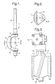
- Figures 1 and 2 in the attached drawing figures show a known arrangement according to the state of the art and Figure 3 shows a known ball segment valve which contains an arrangement according to Figs 1 and 2, where Fig. 2 shows the arrangement in a view along II-II in Fig. 1.
- the arrangement 1 is manufactured by machining of a single casting and consists of a rotating spindle 2, a journal bar 3 and, between these, a valve body 4 which is connected to the rotating spindle 2 and to the journal bar 3 by a pair of legs 5, 6.
- the valve body 4 has a sealing surface 7 with the shape of a spherical segment.
- a valve housing consists of two halves 10, 11, interconnected by means of flange connection in a diagonal dividing plane 12.
- the rotating spindle 2 is inserted into one valve housing piece 10 and the journal bar 3 into the other valve housing piece 11, after which the two valve housing pieces 10, 11 are interconnected by screw connection.
- An adjusting device 13 is connected to the rotating spindle 2 for rotation of the arrangement 1 and with this of the valve body 4, with the spherical sealing surface 7 sliding against a non-annular valve seat in the valve housing half 10.
- each arrangement 1 is unique to each valve size which means little or no possibility of standardization.
- manufacture of the valve housing with two valve housing halves involves complications as far as both casting and machining are concerned and with this increased costs. As far as the manufacture of the valve housing is concerned also, there are few or no possibilities of standardization.
- EP 0 346 216 discloses a ball segment valve of the type described in the above preamble. It is a disadvantage with that valve that it is not possible to use a rotating unit made from a single, that is to say a monolithic, cast piece of material, such that the rotating unit will consist of a rotating spindle, above, and a journal bar which is coaxial with the rotating spindle, because such rotating unit can not be mounted in the valve housing of the known patent. Instead the rotating unit must be manufactured in a plurality of details, which need to be assembled after they have been mounted in the valve housing.
- US 3,722,545 describes a ball segment valve, in which the valve housing is formed in one piece, the valve body with associated rotating spindle and journal mounting being designed to be introduced into the valve housing from the side of the rotating spindle and the adjusting device.
- a very large hole is arranged on said side of the valve housing, which is a disadvantage.
- such a large hole prevents so-called clamping execution of the valve housing. This is because such execution requires it to be possible for bolts to extend between consecutive pipelines, past the valve housing. A hole of the size in question prevents this.
- valve body, the valve spindle, an annular bearing pin on the opposite side of the rotating spindle and the connecting legs to the valve body are made in one or more pieces or as two or more parts.
- a connection has to be brought about between the rotating spindle and other parts in the construction, and possibly also between said annular journal bar and the arrangement in general.
- screw connections which are exposed to considerable torsion forces, slight play arises gradually.
- the presence of such axial connections established by screw connections or with the aid of other fastening elements between the rotating spindle and other parts in the arrangement therefore constitutes a disadvantage.
- US 4,989,833 discloses a ball segment valve, in which the valve body with associated legs is, on assembly, introduced into the valve housing through the outlet opening, after which the rotating spindle and the journal bar are introduced from their respective directions and are connected to the legs inside the valve housing.
- the construction represents a typical example of axial connections in the form of screw connections or similar fastening elements between the rotating spindle and the journal bar on the one hand and the torque-transmitting legs of the valve body on the other hand.
- the aim of the invention is to provide a ball segment valve and an arrangement of such a ball segment valve according to the introduction above but which does not suffer from said disadvantages of the known art. More specifically, the invention aims to provide a ball segment valve and an arrangement which satisfy the following conditions:
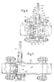
- a ball segment valve is generally designated by number 20. It has a valve housing 23 ofthe so-called clamping type which means that the valve 20 is clamped between flanges 17, 18 on consecutive pipeline sections 21, 22 with the aid of screws 19 with seals arranged between the ends of the pipe sections and the end walls of the valve housing 23.
- the main parts of the valve 20 consist of said valve housing 23 and a valve housing cover 24, a unit 25 which in this text is called a rotating unit and a valve body 26 with a spherical sealing surface 27, together with a valve seat ring 28, a spring washer 29 and a covering washer 30.
- the valve housing 23 is cast in one piece with an inlet opening 33 which is connected to one pipe section 21 and an outlet opening 34 which faces the other pipe section 22. Between the openings, a flow duct 32 extends through the valve housing.
- the neck 35 ends in a shoulder 36 on which an adjusting device (not shown) for rotating the rotating unit 25 is mounted.
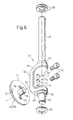
- the rotating unit 25 is made from a single, that is to say monolithic, cast piece of material. It consists of said rotating spindle 41, a bow 42 and a journal bar 43 which is coaxial with the rotating spindle 41.
- the bow 42 consists of a yoke 45 and a pair of legs 46, 47 which connect the yoke 45 to the rotating spindle 41 and the journal bar 43 respectively.
- the yoke 45 has a face-milled side 48 which lies at a distance from and is parallel to the centre line 49 through the rotating spindle 41 and the journal bar 43, which is also the axis of rotation of the rotating unit 25. Extending through the yoke 45 are, on the one hand, a central cylindrical through-hole 50 and, on the other hand, on either side of the central hole 50, a pair of through-holes 51 for fastening screws 52 for the valve body 26.
- the centre line/axis of rotation 49 of the rotating unit intersects the centre 76 of the sphere, of which the spherical sealing surface 27 of the valve body constitutes a part.
- the rotating spindle 41 has in its outer end a keyway in a conventional manner for a key 53 for imparting torque to the rotating spindle 41 and with this to the entire rotating unit 25 from the adjusting device (not shown).
- a first annular flange part 55 with a greater diameter than the main part of the rotating spindle 41 and, in the transition between the other leg 47 and the journal bar 43, there is a second similar annular flange part 56.
- the valve housing wall and the valve housing cover 24 there are corresponding annular recesses 57 and 58 respectively.
- the cover 24 consists of a rectangular plate 63 which covers a rectangular hole 64 in the valve housing wall, which is opposite the through-hole 40 for the rotating spindle 41.
- the rectangular hole 64 extends in the axial direction of the valve housing 23 and has a width which only slightly exceeds the greatest width of the rotating unit 25, more specifically only slightly exceeds the width of the yoke 45, and a length which only slightly exceeds the maximum extent of the rotating unit 25 in a plane at right angles to the plane side 48 of the yoke 45, coinciding with the centre line 49.
- On the plate 63 there is a bearing housing 65 which forms a sliding bearing for the journal bar 43 which is hard chromium-plated.
- the cover 63 is fastened, by means of screws 66 which extend through through-holes in the plane plate 24, to the valve housing 23 which is face-milled on the outside around the hole 64.
- the valve body 26 has a geometrically very simple, rotationally symmetrical shape which is very easy to produce by machining in an automatically operating machine tool More specifically, the valve body consists of a spherical segment 70 with a spherical sealing surface 27 and a plane rear side 71 which, according to the embodiment, is parallel to a cutting-off plane which defines the spherical surface 27. Between the spherical surface 27 and the rear side 71, there is a circumferential edge 72. The spherical surface 27 is polished to a high surface fineness. According to the embodiment, the circumferential edge 72 is circular and the entire valve body 70 is rotationally symmetrical.
- a central centring pin 73 extends backwards at right angles to the plane of the rear side 71.
- the pin 73 is cylindrical and has a diameter which corresponds to the diameter of the central hole 50 in the yoke 45 so that the pin 73 can be introduced into the hole 50 with a good fit.
- the length of the pin 73 is somewhat smaller than or equal to the length of the hole 50.
- the rotating unit 25 is introduced into the valve housing 23 through the hole 64 with one or more shims 59 slipped over the rotating spindle 41 which is introduced into the through-hole 40.
- One or more shims 60 are slipped in a corresponding manner over the journal bar 43, after which the cover 24 is screwed tight over the hole 64, with the journal bar 43 supported in the bearing housing 65.
- the packings 37 are slipped over the rotating spindle 41 as is the gland 38 which is screwed tight.
- the valve body 26 is introduced through the inlet opening 33 of the valve and the centring pin 73 is introduced into the central hole 50 in the yoke 45 on the rotating unit 41.
- valve body 26 is screwed tight on the yoke 45 with the aid of the screws 52 in the direction from the outlet opening 34 of the valve housing, so that the plane rear side 71 of the valve body 26 is pressed against the plane front side 48 of the yoke 45.
- the seat ring 28 is placed in its valve seat ring groove 75.
- the spring washer 29 is placed over the valve seat ring 28 and the externally threaded covering washer 30 is screwed tight, so that the spring washer 29 is clamped and presses the seat ring firmly into its groove 75. Subsequently, it is verified whether the valve body is centred relative to the seat ring 28.
- the valve is dismantled and new shims 59, 60 are inserted, so that these correct the descrepancy measured. Subsequently, the valve is re-assembled, with the valve body 26 centred relative to the valve seat ring 28.
- the rotating unit 25 and the valve body 26 adopt the position which is shown in Fig. 4, the spherical sealing surface 27 bears sealingly against the seat ring 28 around its entire circumference and the axis of rotation 49 of the rotating unit 25 intersects the centre 76 of the sphere of which the spherical sealing surface 27 constitutes a segment.
- the spherical sealing surface 27 slides against the seat ring 28 and the valve body 26 can, in a manner which is conventional per se, be set in various regulating positions, as explained in the introduction to this description.
- the valve 20 is shown in Fig. 4 clamped between the flanges 17, 18 on the consecutive pipeline sections 21, 22.
- the figure shows that the clamping screws 19 extend between the flanges 17, 18, past the valve 20, without hindering either the neck 35 with the shoulder 36 or the valve housing cover 24 with the plate 63 and the bearing housing 65.
- the rotating unit 25, with certain given dimensions, can be used for valve bodies 26 of different sizes, including different radii of the spherical sealing surface 27, within a certain size range which means certain standardization in manufacture and stock-keeping is possible.
- the cover 24 also can be used as a standardized component for different embodiments of valve housing and/or within a certain size range. This is illustrated by the exemplary embodiment which is shown in Fig. 7, in which a cover 24 of the same design as in the preceding embodiment is used to close a hole 64' in a valve housing 23' of a completely design, namely a so-called flanged embodiment.
- the hole 64' and the cover 24 are in this case turned through 180° compared with the embodiment according to Fig. 4 and Fig.
- valve body including the centring pin 73
- the valve body including the centring pin 73
- the spherical sealing surface of the valve body can also be modified and supplemented by arrangements for improving the regulating characteristic of the valve, which has been mentioned already in the introduction to this description.
- the specific design of the valve seat does not constitute a part ofthe invention. As an example, it can be mentioned that it can be constituted by a fixed, circumferential edge in the valve housing or, as in the cases illustrated, by a ring made of metal or ceramic or of an elastomeric material or of a composite materiaL Different embodiments of the valve housing also have been shown and referred to above.
Landscapes
- General Engineering & Computer Science (AREA)
- Engineering & Computer Science (AREA)
- Mechanical Engineering (AREA)
- Taps Or Cocks (AREA)
- Valve Housings (AREA)
- Multiple-Way Valves (AREA)
- Check Valves (AREA)
- Prostheses (AREA)
- External Artificial Organs (AREA)
- Medicines Containing Material From Animals Or Micro-Organisms (AREA)
- Mechanically-Actuated Valves (AREA)
- Lift Valve (AREA)
- Details Of Valves (AREA)
- Sliding Valves (AREA)
- Pens And Brushes (AREA)
- Transition And Organic Metals Composition Catalysts For Addition Polymerization (AREA)
Applications Claiming Priority (2)
| Application Number | Priority Date | Filing Date | Title |
|---|---|---|---|
| SE9600261A SE506438C2 (sv) | 1996-01-25 | 1996-01-25 | Kulsegmentventil samt anordning vid kulsegmentventil |
| SE9600261 | 1996-01-25 |
Publications (2)
| Publication Number | Publication Date |
|---|---|
| EP0786611A1 EP0786611A1 (en) | 1997-07-30 |
| EP0786611B1 true EP0786611B1 (en) | 2001-08-29 |
Family
ID=20401136
Family Applications (1)
| Application Number | Title | Priority Date | Filing Date |
|---|---|---|---|
| EP96203433A Expired - Lifetime EP0786611B1 (en) | 1996-01-25 | 1996-12-04 | Ball segment valve |
Country Status (14)
| Country | Link |
|---|---|
| US (1) | US5820103A (enExample) |
| EP (1) | EP0786611B1 (enExample) |
| JP (1) | JPH09210223A (enExample) |
| KR (1) | KR100468304B1 (enExample) |
| AT (1) | ATE204966T1 (enExample) |
| AU (1) | AU710573B2 (enExample) |
| BR (1) | BR9700762A (enExample) |
| CA (1) | CA2195992C (enExample) |
| DE (1) | DE69614822T2 (enExample) |
| NO (1) | NO308227B1 (enExample) |
| PL (1) | PL182872B1 (enExample) |
| SE (1) | SE506438C2 (enExample) |
| SG (1) | SG46762A1 (enExample) |
| ZA (1) | ZA9762B (enExample) |
Families Citing this family (15)
| Publication number | Priority date | Publication date | Assignee | Title |
|---|---|---|---|---|
| DE19818628C2 (de) * | 1998-04-25 | 2001-07-19 | Asg Luftfahrttechnik Und Senso | Ventil, insbesondere Kugelventil |
| US6378842B1 (en) * | 2000-07-20 | 2002-04-30 | Delaware Capital Formation, Inc. | V-ball control valve |
| US6926036B2 (en) * | 2003-01-06 | 2005-08-09 | Honeywell International, Inc. | Fluidic diverter valve with a non-spherical shuttle element |
| JP4828301B2 (ja) * | 2006-05-19 | 2011-11-30 | 日東工器株式会社 | 管継手 |
| KR100957764B1 (ko) * | 2007-10-01 | 2010-05-13 | 서광공업 주식회사 | 세그먼트의 분리가 용이한 개폐 밸브 |
| DE102010033952B4 (de) * | 2010-08-10 | 2012-05-03 | Viega Gmbh & Co. Kg | Absperrhahn für den Installationsbereich |
| TW201226751A (en) | 2010-12-29 | 2012-07-01 | Zipson Steel Ind Co Ltd | Arc valve |
| CA3039775A1 (en) | 2016-10-17 | 2018-04-26 | Fisher Controls International Llc | Yoke for rotary valve |
| CN106523719A (zh) * | 2016-11-29 | 2017-03-22 | 陈曙光 | 一种凹板三偏心蝶阀 |
| US11519509B2 (en) | 2020-02-14 | 2022-12-06 | Crane Chempharma & Energy Corp. | Valve with unobstructed flow path having increased flow coefficient |
| US11946557B2 (en) | 2020-02-14 | 2024-04-02 | Crane Chempharma & Energy Corp. | Valve with unobstructed flow path having increased flow coefficient |
| US11953113B2 (en) * | 2020-02-14 | 2024-04-09 | Crane Chempharma & Energy Corp. | Valve with unobstructed flow path having increased flow coefficient |
| US11841089B2 (en) | 2020-02-14 | 2023-12-12 | Crane Chempharma & Energy Corp. | Valve with unobstructed flow path having increased flow coefficient |
| US11971117B2 (en) * | 2021-01-13 | 2024-04-30 | Advanced Control Products, Llc | Valve assemblies |
| CN113007376A (zh) * | 2021-02-21 | 2021-06-22 | 段井胜 | 一种防堵塞球阀 |
Family Cites Families (17)
| Publication number | Priority date | Publication date | Assignee | Title |
|---|---|---|---|---|
| US3301271A (en) * | 1964-08-03 | 1967-01-31 | John A Burke | Anglecock |
| US3379408A (en) * | 1965-02-08 | 1968-04-23 | Acf Ind Inc | Eccentric plug valve |
| CA982104A (en) * | 1972-08-07 | 1976-01-20 | Brunswick Corporation | Rotary plug valve |
| JPS5050122U (enExample) * | 1973-09-03 | 1975-05-16 | ||
| JPS50136823U (enExample) * | 1974-04-26 | 1975-11-11 | ||
| US3985334A (en) * | 1974-07-24 | 1976-10-12 | International Telephone And Telegraph Corporation | Ball valve |
| JPS52105328A (en) * | 1976-02-27 | 1977-09-03 | Honeywell Gmbh | Rotary control valve |
| JPS541431A (en) * | 1977-06-06 | 1979-01-08 | Kitamura Barubu Seizou Kk | Eccentric rotary valve |
| US4214732A (en) * | 1978-05-17 | 1980-07-29 | Kamyr Valves, Inc. | Side-split ball valve construction |
| JPS56170365U (enExample) * | 1980-05-20 | 1981-12-16 | ||
| JPS5761871A (en) * | 1980-09-30 | 1982-04-14 | Motoyama Seisakusho:Kk | Opening closing valve |
| CA1228584A (en) * | 1984-03-15 | 1987-10-27 | 596801 Ontario Limited | Ball valve |
| FR2632377B1 (fr) * | 1988-06-07 | 1990-09-07 | Neu Ets | Vanne a calotte spherique |
| JPH0814336B2 (ja) * | 1989-10-02 | 1996-02-14 | 株式会社巴技術研究所 | バタフライ弁 |
| US5016857A (en) * | 1989-09-15 | 1991-05-21 | Fisher Controls International, Inc. | Control element for a ball valve |
| JPH05332460A (ja) * | 1992-06-03 | 1993-12-14 | Hans D Baumann | 偏心回転プラグ弁 |
| JPH07260016A (ja) * | 1994-03-18 | 1995-10-13 | Motoyama Seisakusho:Kk | 偏心回転形流量調整弁 |
-
1996
- 1996-01-25 SE SE9600261A patent/SE506438C2/sv not_active IP Right Cessation
- 1996-12-04 AT AT96203433T patent/ATE204966T1/de active
- 1996-12-04 EP EP96203433A patent/EP0786611B1/en not_active Expired - Lifetime
- 1996-12-04 DE DE69614822T patent/DE69614822T2/de not_active Expired - Lifetime
- 1996-12-20 SG SG1996011872A patent/SG46762A1/en unknown
- 1996-12-30 NO NO965620A patent/NO308227B1/no not_active IP Right Cessation
- 1996-12-31 AU AU76548/96A patent/AU710573B2/en not_active Expired
-
1997
- 1997-01-03 ZA ZA9762A patent/ZA9762B/xx unknown
- 1997-01-22 KR KR1019970001739A patent/KR100468304B1/ko not_active Expired - Lifetime
- 1997-01-24 PL PL97318094A patent/PL182872B1/pl unknown
- 1997-01-24 CA CA002195992A patent/CA2195992C/en not_active Expired - Lifetime
- 1997-01-24 BR BR9700762A patent/BR9700762A/pt not_active Application Discontinuation
- 1997-01-24 US US08/788,698 patent/US5820103A/en not_active Expired - Lifetime
- 1997-01-27 JP JP9012694A patent/JPH09210223A/ja active Pending
Also Published As
| Publication number | Publication date |
|---|---|
| KR970059549A (ko) | 1997-08-12 |
| SG46762A1 (en) | 1998-02-20 |
| NO965620L (no) | 1997-07-28 |
| JPH09210223A (ja) | 1997-08-12 |
| EP0786611A1 (en) | 1997-07-30 |
| CA2195992A1 (en) | 1997-07-26 |
| ZA9762B (en) | 1997-07-11 |
| BR9700762A (pt) | 1998-10-06 |
| US5820103A (en) | 1998-10-13 |
| SE506438C2 (sv) | 1997-12-15 |
| CA2195992C (en) | 2005-09-20 |
| ATE204966T1 (de) | 2001-09-15 |
| PL182872B1 (pl) | 2002-03-29 |
| AU7654896A (en) | 1997-07-31 |
| SE9600261D0 (sv) | 1996-01-25 |
| PL318094A1 (en) | 1997-08-04 |
| NO308227B1 (no) | 2000-08-14 |
| SE9600261L (sv) | 1997-07-26 |
| KR100468304B1 (ko) | 2005-04-14 |
| DE69614822T2 (de) | 2002-03-28 |
| NO965620D0 (no) | 1996-12-30 |
| DE69614822D1 (de) | 2001-10-04 |
| AU710573B2 (en) | 1999-09-23 |
Similar Documents
| Publication | Publication Date | Title |
|---|---|---|
| EP0786611B1 (en) | Ball segment valve | |
| EP0947681B1 (en) | Clamshell throttle valve assembly | |
| US6076799A (en) | Rotary valve actuator and linkage | |
| EP2299152B1 (en) | Ball valve with anti-rotational pressure plate | |
| US5735307A (en) | Valve interchangeable between angle and straight | |
| US5186433A (en) | Adjustable eccentric valve | |
| EP0888509B1 (en) | Rotary valve actuator and linkage | |
| EP0063857B1 (en) | Multi-component valve which can be assembled in a straight line or in an elbow configuration | |
| US3697043A (en) | Ball valve | |
| JPH09210223A5 (enExample) | ||
| US4558605A (en) | Valve actuator coupling | |
| CA2033842C (en) | Pipe coupling with in-coupling flow | |
| US3982727A (en) | Flangeless valve | |
| US5269638A (en) | Spherical pipe switch with single channel or double channel cock | |
| EP0264340B1 (en) | Valve having a rotatable cage | |
| US4683906A (en) | Trunnion type ball valve | |
| US20070023727A1 (en) | Butterfly valve | |
| CA1060188A (en) | Method of manufacturing a butterfly valve | |
| US4621790A (en) | Butterfly valve | |
| US4964435A (en) | Shuttle valve | |
| JP3290275B2 (ja) | ボールバルブ | |
| WO2025197409A1 (ja) | バタフライ弁 | |
| EP1678432B1 (en) | Adjustable sealing means | |
| KR200395167Y1 (ko) | 밸브 | |
| KR100654245B1 (ko) | 구루빙형 버터플라이 밸브 및 이의 밸브 몸체 제조방법 |
Legal Events
| Date | Code | Title | Description |
|---|---|---|---|
| PUAI | Public reference made under article 153(3) epc to a published international application that has entered the european phase |
Free format text: ORIGINAL CODE: 0009012 |
|
| AK | Designated contracting states |
Kind code of ref document: A1 Designated state(s): AT BE CH DE DK ES FI FR GB IE IT LI LU NL PT |
|
| 17P | Request for examination filed |
Effective date: 19971124 |
|
| 17Q | First examination report despatched |
Effective date: 20000302 |
|
| GRAG | Despatch of communication of intention to grant |
Free format text: ORIGINAL CODE: EPIDOS AGRA |
|
| RIC1 | Information provided on ipc code assigned before grant |
Free format text: 7F 16K 5/20 A, 7F 16K 27/08 B |
|
| RTI1 | Title (correction) |
Free format text: BALL SEGMENT VALVE |
|
| GRAG | Despatch of communication of intention to grant |
Free format text: ORIGINAL CODE: EPIDOS AGRA |
|
| GRAH | Despatch of communication of intention to grant a patent |
Free format text: ORIGINAL CODE: EPIDOS IGRA |
|
| GRAH | Despatch of communication of intention to grant a patent |
Free format text: ORIGINAL CODE: EPIDOS IGRA |
|
| ITF | It: translation for a ep patent filed | ||
| GRAA | (expected) grant |
Free format text: ORIGINAL CODE: 0009210 |
|
| AK | Designated contracting states |
Kind code of ref document: B1 Designated state(s): AT BE CH DE DK ES FI FR GB IE IT LI LU NL PT |
|
| PG25 | Lapsed in a contracting state [announced via postgrant information from national office to epo] |
Ref country code: LI Free format text: LAPSE BECAUSE OF FAILURE TO SUBMIT A TRANSLATION OF THE DESCRIPTION OR TO PAY THE FEE WITHIN THE PRESCRIBED TIME-LIMIT Effective date: 20010829 Ref country code: CH Free format text: LAPSE BECAUSE OF FAILURE TO SUBMIT A TRANSLATION OF THE DESCRIPTION OR TO PAY THE FEE WITHIN THE PRESCRIBED TIME-LIMIT Effective date: 20010829 |
|
| REF | Corresponds to: |
Ref document number: 204966 Country of ref document: AT Date of ref document: 20010915 Kind code of ref document: T |
|
| REG | Reference to a national code |
Ref country code: CH Ref legal event code: EP |
|
| REG | Reference to a national code |
Ref country code: IE Ref legal event code: FG4D |
|
| REF | Corresponds to: |
Ref document number: 69614822 Country of ref document: DE Date of ref document: 20011004 |
|
| ET | Fr: translation filed | ||
| PG25 | Lapsed in a contracting state [announced via postgrant information from national office to epo] |
Ref country code: PT Free format text: LAPSE BECAUSE OF FAILURE TO SUBMIT A TRANSLATION OF THE DESCRIPTION OR TO PAY THE FEE WITHIN THE PRESCRIBED TIME-LIMIT Effective date: 20011129 Ref country code: DK Free format text: LAPSE BECAUSE OF FAILURE TO SUBMIT A TRANSLATION OF THE DESCRIPTION OR TO PAY THE FEE WITHIN THE PRESCRIBED TIME-LIMIT Effective date: 20011129 |
|
| PG25 | Lapsed in a contracting state [announced via postgrant information from national office to epo] |
Ref country code: LU Free format text: LAPSE BECAUSE OF NON-PAYMENT OF DUE FEES Effective date: 20011204 Ref country code: IE Free format text: LAPSE BECAUSE OF FAILURE TO SUBMIT A TRANSLATION OF THE DESCRIPTION OR TO PAY THE FEE WITHIN THE PRESCRIBED TIME-LIMIT Effective date: 20011204 |
|
| REG | Reference to a national code |
Ref country code: GB Ref legal event code: IF02 |
|
| PG25 | Lapsed in a contracting state [announced via postgrant information from national office to epo] |
Ref country code: ES Free format text: LAPSE BECAUSE OF FAILURE TO SUBMIT A TRANSLATION OF THE DESCRIPTION OR TO PAY THE FEE WITHIN THE PRESCRIBED TIME-LIMIT Effective date: 20020228 |
|
| REG | Reference to a national code |
Ref country code: CH Ref legal event code: PL |
|
| PLBE | No opposition filed within time limit |
Free format text: ORIGINAL CODE: 0009261 |
|
| STAA | Information on the status of an ep patent application or granted ep patent |
Free format text: STATUS: NO OPPOSITION FILED WITHIN TIME LIMIT |
|
| 26N | No opposition filed | ||
| REG | Reference to a national code |
Ref country code: IE Ref legal event code: MM4A |
|
| REG | Reference to a national code |
Ref country code: FR Ref legal event code: PLFP Year of fee payment: 20 |
|
| PGFP | Annual fee paid to national office [announced via postgrant information from national office to epo] |
Ref country code: GB Payment date: 20151222 Year of fee payment: 20 Ref country code: FI Payment date: 20151217 Year of fee payment: 20 Ref country code: IT Payment date: 20151215 Year of fee payment: 20 |
|
| PGFP | Annual fee paid to national office [announced via postgrant information from national office to epo] |
Ref country code: NL Payment date: 20151217 Year of fee payment: 20 Ref country code: BE Payment date: 20151217 Year of fee payment: 20 Ref country code: AT Payment date: 20151217 Year of fee payment: 20 |
|
| PGFP | Annual fee paid to national office [announced via postgrant information from national office to epo] |
Ref country code: DE Payment date: 20151223 Year of fee payment: 20 |
|
| PGFP | Annual fee paid to national office [announced via postgrant information from national office to epo] |
Ref country code: FR Payment date: 20151231 Year of fee payment: 20 |
|
| REG | Reference to a national code |
Ref country code: DE Ref legal event code: R071 Ref document number: 69614822 Country of ref document: DE |
|
| REG | Reference to a national code |
Ref country code: NL Ref legal event code: MK Effective date: 20161203 |
|
| REG | Reference to a national code |
Ref country code: GB Ref legal event code: PE20 Expiry date: 20161203 |
|
| REG | Reference to a national code |
Ref country code: AT Ref legal event code: MK07 Ref document number: 204966 Country of ref document: AT Kind code of ref document: T Effective date: 20161204 |
|
| PG25 | Lapsed in a contracting state [announced via postgrant information from national office to epo] |
Ref country code: GB Free format text: LAPSE BECAUSE OF EXPIRATION OF PROTECTION Effective date: 20161203 |