EP0785060A2 - Injection moulding process - Google Patents
Injection moulding process Download PDFInfo
- Publication number
- EP0785060A2 EP0785060A2 EP97100085A EP97100085A EP0785060A2 EP 0785060 A2 EP0785060 A2 EP 0785060A2 EP 97100085 A EP97100085 A EP 97100085A EP 97100085 A EP97100085 A EP 97100085A EP 0785060 A2 EP0785060 A2 EP 0785060A2
- Authority
- EP
- European Patent Office
- Prior art keywords
- workpieces
- carrier system
- workpiece carrier
- phase
- tool
- Prior art date
- Legal status (The legal status is an assumption and is not a legal conclusion. Google has not performed a legal analysis and makes no representation as to the accuracy of the status listed.)
- Granted
Links
- 238000001746 injection moulding Methods 0.000 title claims description 24
- 238000000034 method Methods 0.000 claims abstract description 20
- 230000000694 effects Effects 0.000 claims description 3
- 238000007689 inspection Methods 0.000 claims description 2
- 238000002347 injection Methods 0.000 abstract description 3
- 239000007924 injection Substances 0.000 abstract description 3
- 238000000465 moulding Methods 0.000 abstract 4
- 238000000605 extraction Methods 0.000 abstract 1
- 238000010137 moulding (plastic) Methods 0.000 abstract 1
- 230000007257 malfunction Effects 0.000 description 2
- 238000010586 diagram Methods 0.000 description 1
- 238000007493 shaping process Methods 0.000 description 1
- 230000000007 visual effect Effects 0.000 description 1
Images


Classifications
-
- B—PERFORMING OPERATIONS; TRANSPORTING
- B29—WORKING OF PLASTICS; WORKING OF SUBSTANCES IN A PLASTIC STATE IN GENERAL
- B29C—SHAPING OR JOINING OF PLASTICS; SHAPING OF MATERIAL IN A PLASTIC STATE, NOT OTHERWISE PROVIDED FOR; AFTER-TREATMENT OF THE SHAPED PRODUCTS, e.g. REPAIRING
- B29C45/00—Injection moulding, i.e. forcing the required volume of moulding material through a nozzle into a closed mould; Apparatus therefor
- B29C45/17—Component parts, details or accessories; Auxiliary operations
- B29C45/76—Measuring, controlling or regulating
- B29C45/766—Measuring, controlling or regulating the setting or resetting of moulding conditions, e.g. before starting a cycle
-
- B—PERFORMING OPERATIONS; TRANSPORTING
- B29—WORKING OF PLASTICS; WORKING OF SUBSTANCES IN A PLASTIC STATE IN GENERAL
- B29C—SHAPING OR JOINING OF PLASTICS; SHAPING OF MATERIAL IN A PLASTIC STATE, NOT OTHERWISE PROVIDED FOR; AFTER-TREATMENT OF THE SHAPED PRODUCTS, e.g. REPAIRING
- B29C37/00—Component parts, details, accessories or auxiliary operations, not covered by group B29C33/00 or B29C35/00
- B29C37/0003—Discharging moulded articles from the mould
-
- B—PERFORMING OPERATIONS; TRANSPORTING
- B29—WORKING OF PLASTICS; WORKING OF SUBSTANCES IN A PLASTIC STATE IN GENERAL
- B29C—SHAPING OR JOINING OF PLASTICS; SHAPING OF MATERIAL IN A PLASTIC STATE, NOT OTHERWISE PROVIDED FOR; AFTER-TREATMENT OF THE SHAPED PRODUCTS, e.g. REPAIRING
- B29C45/00—Injection moulding, i.e. forcing the required volume of moulding material through a nozzle into a closed mould; Apparatus therefor
- B29C45/17—Component parts, details or accessories; Auxiliary operations
- B29C45/40—Removing or ejecting moulded articles
- B29C45/42—Removing or ejecting moulded articles using means movable from outside the mould between mould parts, e.g. robots
-
- B—PERFORMING OPERATIONS; TRANSPORTING
- B29—WORKING OF PLASTICS; WORKING OF SUBSTANCES IN A PLASTIC STATE IN GENERAL
- B29C—SHAPING OR JOINING OF PLASTICS; SHAPING OF MATERIAL IN A PLASTIC STATE, NOT OTHERWISE PROVIDED FOR; AFTER-TREATMENT OF THE SHAPED PRODUCTS, e.g. REPAIRING
- B29C45/00—Injection moulding, i.e. forcing the required volume of moulding material through a nozzle into a closed mould; Apparatus therefor
- B29C45/17—Component parts, details or accessories; Auxiliary operations
- B29C45/76—Measuring, controlling or regulating
- B29C45/7686—Measuring, controlling or regulating the ejected articles, e.g. weight control
-
- B—PERFORMING OPERATIONS; TRANSPORTING
- B29—WORKING OF PLASTICS; WORKING OF SUBSTANCES IN A PLASTIC STATE IN GENERAL
- B29C—SHAPING OR JOINING OF PLASTICS; SHAPING OF MATERIAL IN A PLASTIC STATE, NOT OTHERWISE PROVIDED FOR; AFTER-TREATMENT OF THE SHAPED PRODUCTS, e.g. REPAIRING
- B29C45/00—Injection moulding, i.e. forcing the required volume of moulding material through a nozzle into a closed mould; Apparatus therefor
- B29C45/17—Component parts, details or accessories; Auxiliary operations
- B29C45/76—Measuring, controlling or regulating
- B29C45/7626—Measuring, controlling or regulating the ejection or removal of moulded articles
- B29C2045/7633—Take out or gripping means
-
- B—PERFORMING OPERATIONS; TRANSPORTING
- B29—WORKING OF PLASTICS; WORKING OF SUBSTANCES IN A PLASTIC STATE IN GENERAL
- B29C—SHAPING OR JOINING OF PLASTICS; SHAPING OF MATERIAL IN A PLASTIC STATE, NOT OTHERWISE PROVIDED FOR; AFTER-TREATMENT OF THE SHAPED PRODUCTS, e.g. REPAIRING
- B29C33/00—Moulds or cores; Details thereof or accessories therefor
- B29C33/44—Moulds or cores; Details thereof or accessories therefor with means for, or specially constructed to facilitate, the removal of articles, e.g. of undercut articles
- B29C33/442—Moulds or cores; Details thereof or accessories therefor with means for, or specially constructed to facilitate, the removal of articles, e.g. of undercut articles with mechanical ejector or drive means therefor
Definitions
- the invention relates to a method for injection molding of workpieces with a tool of a plastic injection molding machine, in which, in a first phase during the start-up of the plastic injection molding machine, workpieces are sprayed in individual cycles on a trial basis, demoulded and checked after opening the tool, and in which the working speed of the plastic injection molding machine is then increased in a second phase without checking the workpieces to the nominal speed if the test-molded parts are of a predetermined quality.
- a tool carrier system is a holder for a large number of workpieces.
- the workpiece carrier system can either approach the mold cavities in the opening direction of the tool and then remove the workpieces from the mold cavities, but alternatively it is also possible to let the workpiece carrier system only retract laterally and transfer the workpieces from the mold cavities to the workpiece carrier system, for example. with retractable ejector pins.
- the operator of a plastic injection molding machine proceeds by first driving a few cycles "by hand" when starting the machine. This means that any existing handling system initially remains out of operation and the mold cavities of the tool are injected in a first injection cycle. The tool is then opened and the workpieces are ejected using the ejector pins. They then fall down into a container provided. The fitter can now visually check whether the workpieces are of the desired quality and whether there are as many workpieces in the container as there are mold cavities. Depending on the result of the check, the setter will then run one or more test cycles until he finds that workpieces of the desired quality are being produced in all mold cavities.
- the handling system is only switched on when this result has been determined, so that in the subsequent cycles the workpieces are removed from the tool by means of the handling system.
- This phase of the start-up operation can also initially take place with a reduced working speed of the machine and the handling system, as is the case e.g. is described in DE 42 19 687 C2.
- the installer can switch the machine to automatic mode and operate it at full working speed.
- the invention is based on the object of developing a method of the type mentioned in such a way that the start-up process of the injection molding machine is significantly shortened.
- This object is achieved in that the workpieces are removed from the mold in the first phase by means of a motor-operated workpiece carrier system, and that the workpiece carrier system is stopped for at least a predetermined time after removal from the mold to check the workpieces.
- the fitter can check the condition of the workpieces more easily.
- the workpieces are arranged in a clear form on the workpiece carrier system, so that they do not have to be rotated individually into a specific position for viewing. Furthermore, it is immediately noticeable on the workpiece carrier system if one of the workpieces is missing because the associated mold cavity has not been sprayed out at all. All of this is achieved by a surprisingly simple measure, namely the use of the workpiece carrier system as soon as the machine starts up, only the workpiece carrier system having to be stopped in a certain position, or in several positions so that the fitter can carry out a visual or other check.
- the workpiece carrier system is stopped in a position between two tool halves.
- This measure has the advantage that the slightest interventions in the control are required and that the workpieces can be checked immediately after removal from the mold, if they are still inside the tool, i.e. between the two tool halves of a common tool.
- the tool halves of the first phase are at a first distance and are spaced a second, smaller distance in the open position in the second phase.
- This measure has the advantage that a somewhat larger opening stroke of the tool has to be set only during the start-up of the machine, which permits a better and more reliable viewing of the workpieces by the fitter. As soon as this first phase has been completed, the opening thrust can be reduced accordingly with increased working speed and thus reduced cycle time of the machine.
- This measure has the advantage that an even better observation of the workpieces or other control of the workpieces by means of measuring devices and the like is possible.
- the workpieces are checked optically.
- This measure has the advantage that the check can be carried out either by the installer himself or by simple measuring devices.
- the workpieces are held in the workpiece carrier system by means of external force and checked via the effect of the external force.
- This measure has the advantage that a largely automated inspection of the workpieces is possible, in particular with regard to whether there are workpieces in all the receptacles of the workpiece carrier system.
- the workpieces are held in the workpiece carrier system by means of negative pressure and the negative pressure is checked in a line system of the workpiece carrier system.
- This measure has the advantage that a particularly simple check is possible. If e.g. If a mold cavity of the tool has not been sprayed out and therefore the associated receptacle of the workpiece carrier system is not provided with a workpiece, air can flow freely into the line system there, with the result that the negative pressure in the line system has a value deviating from a standard value. This deviating value can be easily detected by means of a pressure sensor and fed to a malfunction indicator.
- the workpiece carrier system can be moved in several axes.
- This measure has the advantage that the effort in the tool itself can be reduced.
- the workpieces are removed from the tool by means of ejectors and transferred to the workpiece carrier system.
- a particularly good effect is achieved in exemplary embodiments of the invention if, after the end of the first phase and before the start of the second phase in an intermediate phase, only the working speed of the plastic injection molding machine is increased, but the checking of the workpieces is maintained.
- This measure has the advantage that the possible interferences are switched off one after the other, so that a particularly safe start-up of the machine is possible.
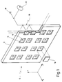
- FIG. 1 designates overall a workpiece carrier system as can be used within a handling system of a plastic injection molding machine known per se.
- Plastic injection molding machines of the type of interest here are generally known and therefore do not need to be explained in more detail.
- the workpiece carrier system 10 has a carrier plate 12 which can be moved in a plurality of coordinate directions x, y and z by means of travel units (not shown).
- the carrier plate 12 has a plurality of recesses 14, which are each adapted to the shape of the workpieces to be produced.
- each recess 14 is connected at the rear to a channel 15.
- the channels 15 are connected to a line system 18.
- the line system 18 leads overall to a vacuum connection 19.
- the pressure in the line system 18 can be monitored by means of a vacuum control display 20.
- the workpieces 16 can be held in the line system 18 by applying a negative pressure. If, however, one or more of the recesses 14 is not equipped with a workpiece 16 as a result of a fault, the build-up of the negative pressure in the line system 18 is hindered because the associated channel 15 connects the line system 18 to the ambient pressure in the relevant recess 14.
- the vacuum control display 20 will detect a fault in this case because a sufficiently large negative pressure cannot develop in the line system 18. For this purpose, the vacuum control display 20 is connected to an alarm system, not shown.
- FIG. 2 shows a top view of two extremely schematic tool halves 30a, 30b, which are each provided with mold cavities 32a, 32b.
- the tool halves 30a, 30b are in the open state.
- the mold cavity 32a, 32b was previously injected with plastic.
- the arrangement is such that the workpiece 16 is in the mold cavity 32a of the tool half 30a.
- all of this is only to be understood as an example.
- a handling system with a workpiece carrier system 10 according to FIG. 1 now moves laterally into the space between the tool halves 30a, 30b.
- the tool halves 30a, 30b are spaced apart by a relatively large opening stroke Z 1 , which can be reduced to Z 2 in the later automatic operation of the machine.
- the movement starts from a first position 40 at a lateral distance from the tool halves 30a, 30b.
- the workpiece carrier system 10 now moves in the direction -x between the tool halves 30a, 30b until a second position 41 is reached. From there, the workpiece carrier system 10 travels in the z direction to a third position 42. In the third position 42, the workpiece 16 is taken over.
- the workpiece 16 is either gripped by the tool carrier system 10 or ejected from the corresponding tool half 30a by means of ejectors, as indicated by an arrow 34 in FIG. 2.
- Fig. 3 shows that the workpiece carrier system 10 first moves in the direction -z to a fourth position 43 and then in the x-direction from the tool halves 30a, 30b to a fifth position 44 (optional) and finally to a sixth Position 45, which corresponds to the first position 40.
- the special feature of the method according to the invention is that this sequence of movements is also used when starting up the plastic injection molding machine, specifically from the first test cycle, which initially only serves to test the functioning of the injection molding process in the machine.
- the sequence of movements is modified in terms of time, as will now be explained with reference to FIGS. 4 to 6:
- a time interval ⁇ 1 t is now provided for the demolding or the transfer of the workpiece 16 from t 3 to t 4 .
- the time interval ⁇ 1 t depends on the respective transfer or demolding mechanism and can be almost zero in extreme cases.
- a second time interval ⁇ 2 t then follows the time t 5 , during which the workpiece carrier system 10 remains in the fourth position 43.
- the machine setter can now view and check the workpieces 16 accommodated in the workpiece carrier system 10, both with regard to their nature and with regard to their completeness. 1 that this check can be carried out relatively quickly because the workpieces 16 are in an orderly manner on the carrier plate 12 of the workpiece carrier system 10, for example in the Cartesian arrangement shown.
- the workpiece carrier system 10 is extended again from the time t 6 , specifically from the fourth position 43 in the x direction to the outside.
- the workpiece carrier system 10 can be briefly stopped again in a fifth position 44, namely an intermediate position at time t 7 , for a time interval ⁇ 3 t, in order to carry out a further check if necessary.
- This further check can take place, for example, by means of sensors which, for reasons of space, can only be used outside the tool halves 30a, 30b.
- the vacuum applied in the line system 18 can also be checked, for example, in the intermediate position 44.
- the speeds in the x direction are each designated v x1 and the speeds in the z direction are each designated v z1 .
- the speed profiles shown are to be understood only as examples and that, of course, non-linear profiles or profiles which are varied in some other way can also be used, as long as only the pause shown in the form of the time interval ⁇ 2 t is observed.
- the working speed ie the speed of movement of the workpiece carrier system 10 in the x and z directions
- the working speed can initially be increased according to FIG. 5. This is indicated in FIG. 5 by increased speeds v x2 and v z2 .
- the time profile is otherwise unchanged insofar as the required time intervals ⁇ 1 t, ⁇ 2 t have remained unchanged on the time scale.
- the total cycle time from t 1 to now t 9 * has been shortened because the travel times in the x and z directions have been shortened.
- the installer determines in one or more cycles that there are no faults, he can switch to automatic mode. This is shown in FIG. 6.
- the machine can initially be operated according to FIG. 6 at speeds v x2 , v z2 , which are still significantly below the maximum possible working speeds. Only when it has been determined after a certain number of N cycles (cf. DE 42 19 687 C2) that no malfunction occurs can a switch to an even higher working speed be made.
Landscapes
- Engineering & Computer Science (AREA)
- Manufacturing & Machinery (AREA)
- Mechanical Engineering (AREA)
- Robotics (AREA)
- Injection Moulding Of Plastics Or The Like (AREA)
- Moulds For Moulding Plastics Or The Like (AREA)
- Heating, Cooling, Or Curing Plastics Or The Like In General (AREA)
- Manufacture Of Motors, Generators (AREA)
Abstract
Description
Die Erfindung betrifft ein Verfahren zua Spritzgießen von Werkstücken mit einem Werkzeug einer Kunststoff-Spritzgießmaschine, bei dem in einer ersten Phase während des Anfahrens der Kunststoff-Spritzgießmaschine in einzelnen Zyklen Werkstücke probeweise gespritzt, nach dem Öffnen des Werkzeugs entformt und überprüft werden, und bei dem die Arbeitsgeschwindigkeit der Kunststoff-Spritzgießmaschine dann in einer zweiten Phasen ohne Überprüfung der Werkstücke auf Nenngeschwindigkeit erhöht wird, wenn die probeweise gespritzten Werkstücke von vorbestimmter Qualität sind.The invention relates to a method for injection molding of workpieces with a tool of a plastic injection molding machine, in which, in a first phase during the start-up of the plastic injection molding machine, workpieces are sprayed in individual cycles on a trial basis, demoulded and checked after opening the tool, and in which the working speed of the plastic injection molding machine is then increased in a second phase without checking the workpieces to the nominal speed if the test-molded parts are of a predetermined quality.
Ein Verfahren der vorstehend genannten Art ist allgemein bekannt.A method of the type mentioned above is generally known.
Beim Spritzgießen von Werkstücken entsteht das Problem, daß beim Anfahren der Maschine zunächst Sorge dafür getragen werden muß, daß die Maschine richtig eingerichtet wird, ehe die Maschine im Automatikbetrieb bei hoher Betriebsgeschwindigkeit betrieben werden kann. Das Problem stellt sich insbesondere beim Betrieb von Kunststoff-Spritzgießmaschinen, bei denen die Werkzeuge mit einer Vielzahl von Formhohlräumen versehen sind, so daß bei jedem Spritzyklus eine entsprechende Vielzahl von Werkstücken hergestellt werden kann.When injection molding workpieces, the problem arises that when starting the machine, care must first be taken that the machine is set up correctly before the machine can be operated in automatic mode at high operating speed. The problem arises particularly in the operation of plastic injection molding machines, in which the tools are provided with a large number of mold cavities, so that a corresponding large number of workpieces can be produced in each injection cycle.
Beim Anfahren der Maschine können dabei Fehler unterschiedlicher Art auftreten, die bspw. dadurch verursacht werden, daß der noch nicht vollständig auf Betriebstemperatur befindliche Kunststoff nicht in ausreichender Menge in sämtliche Formhohlräume des Werkzeugs gelangt. Dies kann dadurch auftreten, daß das Werkzeug in seinen Randbereichen noch nicht auf Betriebstemperatur ist.When starting up the machine, errors of various kinds can occur, which are caused, for example, by the fact that the plastic, which is not yet fully at operating temperature, does not reach a sufficient quantity in all mold cavities of the tool. This can occur due to the fact that the edge of the tool is not yet at operating temperature.
Wenn derartige Fehler beim Anfahren der Maschine auftreten, äußert sich dies dadurch, daß einzelne Formhohlräume nur teilweise oder auch gar nicht ausgespritzt werden. Entsprechend werden dann auch keine oder unvollkommene Werkstücke entformt, bspw. durch die im Werkzeug vorhandenen Auswerferstifte. Es kann dann insbesondere bei unvollkommen gespritzten Werkstücken geschehen, daß das Werkstück sich im Formhohlraum schräg stellt und verklemmt, so daß es beim erneuten Schließen der Werkzeughälften zu entsprechenden Kollisionen und Beschädigungen kommen kann.If such errors occur when starting the machine, this is expressed in that individual mold cavities are only partially or not at all sprayed out. Accordingly, no or imperfect workpieces are then removed from the mold, for example by the ejector pins present in the tool. It can then happen, particularly in the case of incompletely injection-molded workpieces, that the workpiece is inclined and jammed in the mold cavity, so that corresponding collisions and damage can occur when the tool halves are closed again.
Bei Kunststoff-Spritzgießmaschinen mit Werkzeugen, die eine Vielzahl von Formhohlräumen aufweisen, ist es ferner bekannt, Handlingsysteme für das Entformen und/oder Entnehmen der Werkstücke einzusetzen, die mit sogenannten Werkstückträgersystemen versehen sind. Unter einem Werkzeugträgersystem versteht man dabei eine Aufnahme für eine Vielzahl von Werkstücken. Mit einem Werkzeugträgersystem innerhalb eines Handlingsystems ist es möglich, z.B. sämtliche Werkstücke aus allen Formhohlräumen des Werkzeugs zu entnehmen, sobald das Werkzeug geöffnet wird. Das Werkstückträgersystem kann dabei entweder in Öffnungsrichtung des Werkzeugs an die Formhohlräume heranfahren und die Werkstücke dann aus den Formhohlräumen entnehmen, alternativ ist es aber auch möglich, das Werkstückträgersystem nur seitlich einfahren zu lassen und die Werkstücke aus den Formhohlräumen an das Werkstückträgersystem zu übergeben, bspw. mit vorfahrbaren Auswerferstiften.In plastic injection molding machines with tools that have a large number of mold cavities, it is also known to use handling systems for demolding and / or removing the To use workpieces that are equipped with so-called workpiece carrier systems. A tool carrier system is a holder for a large number of workpieces. With a tool carrier system within a handling system, it is possible, for example, to remove all workpieces from all mold cavities of the tool as soon as the tool is opened. The workpiece carrier system can either approach the mold cavities in the opening direction of the tool and then remove the workpieces from the mold cavities, but alternatively it is also possible to let the workpiece carrier system only retract laterally and transfer the workpieces from the mold cavities to the workpiece carrier system, for example. with retractable ejector pins.
In der Praxis geht der Einrichter einer Kunststoff-Spritzgießmaschine so vor, daß er beim Anfahren der Maschine zunächst einige Zyklen "von Hand" fährt. Dies bedeutet, daß ein ggf. vorhandenes Handlingsystem zunächst außer Betrieb bleibt und in einem ersten Spritzzyklus die Formhohlräume des Werkzeugs ausgespritzt werden. Das Werkzeug wird dann geöffnet und die Werkstücke werden mittels der Auswerferstifte ausgeworfen. Sie fallen dann nach unten in einen bereitgestellten Behälter. Der Einrichter kann nun optisch überprüfen, ob die Werkstücke von der gewünschten Qualität sind und ob sich im Behälter genauso viele Werkstücke befinden, wie Formhohlräume vorhanden sind. Je nach Ergebnis der Überprüfung wird der Einrichter dann noch einen oder mehrere Probezyklen fahren, und zwar solange, bis er feststellt, daß in sämtlichen Formhohlräumen Werkstücke der gewünschten Qualität erzeugt werden.In practice, the operator of a plastic injection molding machine proceeds by first driving a few cycles "by hand" when starting the machine. This means that any existing handling system initially remains out of operation and the mold cavities of the tool are injected in a first injection cycle. The tool is then opened and the workpieces are ejected using the ejector pins. They then fall down into a container provided. The fitter can now visually check whether the workpieces are of the desired quality and whether there are as many workpieces in the container as there are mold cavities. Depending on the result of the check, the setter will then run one or more test cycles until he finds that workpieces of the desired quality are being produced in all mold cavities.
Erst wenn dieses Ergebnis feststeht, wird das Handlingsystem zugeschaltet, so daß bei den nachfolgenden Zyklen die Werkstücke mittels des Handlingsystems aus dem Werkzeug entnommen werden.The handling system is only switched on when this result has been determined, so that in the subsequent cycles the workpieces are removed from the tool by means of the handling system.
Auch diese Phase des Anfahrbetriebes kann zunächst mit verminderter Arbeitsgeschwindigkeit der Maschine und des Handlingsystems ablaufen, wie dies z.B. in der DE 42 19 687 C2 beschrieben ist. Wenn schließlich feststeht, daß alle Aggregate fehlerfrei arbeiten, kann der Einrichter die Maschine auf Automatikbetrieb umschalten und mit voller Arbeitsgeschwindigkeit betreiben.This phase of the start-up operation can also initially take place with a reduced working speed of the machine and the handling system, as is the case e.g. is described in
Das zuvor geschilderte Einrichten der Maschine ist, wie leicht einsehbar, relativ mühselig und zeitaufwendig, zumal dann, wenn die im Probebetrieb entformten Werkstücke eine große Anzahl haben und zunächst von Hand überprüft werden müssen. Der Einrichter muß dazu den Behälter vom Boden der Maschine aufnehmen, die Werkstücke zählen, von Hand in eine Position bringen, in der er sie optisch überprüfen kann und anschließend entsorgen.The previously described setting up of the machine is, as can be easily seen, relatively cumbersome and time-consuming, especially when the workpieces demolded in trial operation have a large number and must first be checked by hand. To do this, the fitter has to pick up the container from the bottom of the machine, count the workpieces, manually position them in a position in which they can be visually checked and then dispose of them.
Der Erfindung liegt demgegenüber die Aufgabe zugrunde, ein Verfahren der eingangs genannten Art dahingehend weiterzubilden, daß der Anfahrvorgang der Spritzgießmaschine deutlich verkürzt wird.The invention is based on the object of developing a method of the type mentioned in such a way that the start-up process of the injection molding machine is significantly shortened.
Diese Aufgabe wird erfindungsgemäß dadurch gelöst, daß die Werkstücke bereits in der ersten Phase mittels eines motorisch betätigbaren Werkstückträgersystems entformt werden, und daß das Werkstückträgersystem nach dem Entformen zur Überprüfung der Werkstücke für mindestens eine vorbestimmte Zeit angehalten wird.This object is achieved in that the workpieces are removed from the mold in the first phase by means of a motor-operated workpiece carrier system, and that the workpiece carrier system is stopped for at least a predetermined time after removal from the mold to check the workpieces.
Die der Erfindung zugrundeliegende Aufgabe wird auf diese Weise vollkommen gelöst.The object underlying the invention is completely achieved in this way.
Wenn nämlich bereits während des Anfahrens der Kunststoff-Spritzgießmaschine das Handlingsystem mit dem Werkstückträgersystem eingesetzt wird, so kann der Einrichter den Zustand der Werkstücke leichter überprüfen. Auf dem Werkstückträgersystem sind die Werkstücke nämlich in übersichtlicher Form angeordnet, so daß sie nicht einzeln in eine bestimmte Lage zum Betrachten gedreht werden müssen. Ferner fällt am Werkstückträgersystem sofort auf, wenn eines der Werkstücke fehlt, weil der zugehörige Formhohlraum überhaupt nicht ausgespritzt wurde. Erreicht wird all dies durch eine überraschend einfache Maßnahme, nämlich den Einsatz des Werkstückträgersystems bereits beim Anfahren der Maschine, wobei lediglich das Werkstückträgersystem in einer bestimmten Position angehalten werden muß, oder in mehreren Positionen, damit der Einrichter eine optische oder sonstige Kontrolle vornehmen kann.If the handling system with the workpiece carrier system already during the start-up of the plastic injection molding machine is used, the fitter can check the condition of the workpieces more easily. The workpieces are arranged in a clear form on the workpiece carrier system, so that they do not have to be rotated individually into a specific position for viewing. Furthermore, it is immediately noticeable on the workpiece carrier system if one of the workpieces is missing because the associated mold cavity has not been sprayed out at all. All of this is achieved by a surprisingly simple measure, namely the use of the workpiece carrier system as soon as the machine starts up, only the workpiece carrier system having to be stopped in a certain position, or in several positions so that the fitter can carry out a visual or other check.
All dies läßt sich in bekannte Kunststoff-Spritzgießmaschinen mit Handlingsystemen ohne größere Probleme integrieren, weil nur wenige Eingriffe in die Steuerung der Maschine erforderlich sind. Gleichwohl wird erfindungsgemäß eine deutliche Verkürzung der Anfahrzeit erreicht, so daß die Auslastung der Maschine entsprechend erhöht werden kann.All of this can be integrated into known plastic injection molding machines with handling systems without major problems, because only a few interventions in the control of the machine are required. Nevertheless, according to the invention, the start-up time is significantly reduced, so that the utilization of the machine can be increased accordingly.
Bei einer bevorzugten Ausgestaltung der Erfindung wird das Werkstückträgersystem in einer Position zwischen zwei Werkzeughälften angehalten.In a preferred embodiment of the invention, the workpiece carrier system is stopped in a position between two tool halves.
Diese Maßnahme hat den Vorteil, daß die geringsten Eingriffe in die Steuerung erforderlich sind und daß die Werkstücke unmittelbar nach dem Entformen überprüft werden können, wenn sie sich noch innerhalb des Werkzeugs, d.h. zwischen den beiden Werkzeughälften eines üblichen Werkzeugs befinden.This measure has the advantage that the slightest interventions in the control are required and that the workpieces can be checked immediately after removal from the mold, if they are still inside the tool, i.e. between the two tool halves of a common tool.
Besonders bevorzugt ist bei diesem Ausführungsbeispiel, wenn die Werkzeughälften der ersten Phase um einen ersten Abstand und in der zweiten Phase um einen zweiten, kleineren Abstand in der Offenstellung beabstandet sind.It is particularly preferred in this exemplary embodiment if the tool halves of the first phase are at a first distance and are spaced a second, smaller distance in the open position in the second phase.
Diese Maßnahme hat den Vorteil, daß nur während des Anfahrens der Maschine ein etwas größerer Öffnungshub des Werkzeugs eingestellt werden muß, der eine bessere und zuverlässigere Betrachtung der Werkstücke durch den Einrichter gestattet. Sobald diese erste Phase abgeschlossen ist, kann bei erhöhter Arbeitsgeschwindigkeit und damit verminderter Zykluszeit der Maschine auch der Öffnungsschub entsprechend verringert werden.This measure has the advantage that a somewhat larger opening stroke of the tool has to be set only during the start-up of the machine, which permits a better and more reliable viewing of the workpieces by the fitter. As soon as this first phase has been completed, the opening thrust can be reduced accordingly with increased working speed and thus reduced cycle time of the machine.
Darüber hinaus ist es auch möglich, das Werkstückträgersystem in einer Position neben dem Werkzeug anzuhalten.In addition, it is also possible to stop the workpiece carrier system in a position next to the tool.
Diese Maßnahme hat den Vorteil, daß eine noch bessere Beobachtung der Werkstücke oder sonstige Kontrolle der Werkstücke mittels Meßgeräten und dgl. möglich ist.This measure has the advantage that an even better observation of the workpieces or other control of the workpieces by means of measuring devices and the like is possible.
Bei Ausführungsbeispielen der Erfindung werden die Werkstücke optisch überprüft.In embodiments of the invention, the workpieces are checked optically.
Diese Maßnahme hat den Vorteil, daß die Überprüfung entweder durch den Einrichter selbst oder durch einfache Meßgeräte vorgenommen werden kann.This measure has the advantage that the check can be carried out either by the installer himself or by simple measuring devices.
Bei Ausführungsbeispielen der Erfindung werden die Werkstücke mittels Fremdkraft im Werkstückträgersystem gehalten und über die Wirkung der Fremdkraft überprüft.In exemplary embodiments of the invention, the workpieces are held in the workpiece carrier system by means of external force and checked via the effect of the external force.
Diese Maßnahme hat den Vorteil, daß eine weitgehend automatisierte Überprüfung der Werkstücke möglich ist, insbesondere im Hinblick darauf, ob sich in sämtlichen Aufnahmen des Werkstückträgersystems auch Werkstücke befinden. Man kann daher in sehr einfacher und automatisierbarer Weise feststellen, ob alle Formhohlräume des Werkzeugs mit Kunststoff ausgespritzt wurden.This measure has the advantage that a largely automated inspection of the workpieces is possible, in particular with regard to whether there are workpieces in all the receptacles of the workpiece carrier system. One can therefore Determine in a very simple and automated manner whether all mold cavities of the tool have been sprayed with plastic.
Bei einer besonders bevorzugten Variante dieses Ausführungsbeispiels werden die Werkstücke mittels Unterdruck im Werkstückträgersystem gehalten und der Unterdruck wird in einem Leitungssystem des Werkstückträgersystems überprüft.In a particularly preferred variant of this exemplary embodiment, the workpieces are held in the workpiece carrier system by means of negative pressure and the negative pressure is checked in a line system of the workpiece carrier system.
Diese Maßnahme hat den Vorteil, daß eine besonders einfache Überprüfung möglich ist. Wenn nämlich z.B. ein Formhohlraum des Werkzeugs nicht ausgespritzt wurde und damit auch die zugehörige Aufnahme des Werkstückträgersystems nicht mit einem Werkstück versehen wird, so kann dort ungehindert Luft in das Leitungssystem einströmen, mit der Folge, daß der Unterdruck im Leitungssystem einen von einem Normwert abweichenden Wert aufweist. Dieser abweichende Wert kann mittels eines Druckgebers leicht erfaßt und einem Störungsmelder zugeführt werden.This measure has the advantage that a particularly simple check is possible. If e.g. If a mold cavity of the tool has not been sprayed out and therefore the associated receptacle of the workpiece carrier system is not provided with a workpiece, air can flow freely into the line system there, with the result that the negative pressure in the line system has a value deviating from a standard value. This deviating value can be easily detected by means of a pressure sensor and fed to a malfunction indicator.
Besonders bevorzugt ist, wenn das Werkstückträgersystem in mehreren Achsen verfahrbar ist.It is particularly preferred if the workpiece carrier system can be moved in several axes.
Diese Maßnahme hat den Vorteil, daß der Aufwand im Werkzeug selbst verringert werden kann.This measure has the advantage that the effort in the tool itself can be reduced.
Bevorzugt ist besonders, wenn die Werkstücke mittels Austoßern aus dem Werkzeug entformt und dem Werkstückträgersystem übergeben werden.It is particularly preferred if the workpieces are removed from the tool by means of ejectors and transferred to the workpiece carrier system.
In diesem Falle ist es unter Inkaufnahme eines gewissen Mehraufwandes im Werkzeug möglich, das Werkstückträgersystem nur in einer radialen Richtung zur Öffnungsachse des Werkzeugs einzufahren und auszufahren. Auf diese Weise wird die Bewegungssteuerung des Werkstückträgersystems vereinfacht.In this case, it is possible to accept and extend the workpiece carrier system only in a radial direction to the opening axis of the tool while accepting a certain additional outlay in the tool. In this way, the movement control of the workpiece carrier system is simplified.
Eine besonders gute Wirkung wird bei Ausführungsbeispielen der Erfindung dann erzielt, wenn nach Abschluß der ersten Phase und vor Beginn der zweiten Phase in einer Zwischenphase nur die Arbeitsgeschwindigkeit der Kunststoff-Spritzgießmaschine erhöht, die Überprüfung der Werkstücke jedoch beibehalten wird.A particularly good effect is achieved in exemplary embodiments of the invention if, after the end of the first phase and before the start of the second phase in an intermediate phase, only the working speed of the plastic injection molding machine is increased, but the checking of the workpieces is maintained.
Diese Maßnahme hat den Vorteil, daß die möglichen Störeinflüsse nacheinander ausgeschaltet werden, so daß ein besonders sichere Anfahren der Maschine möglich ist.This measure has the advantage that the possible interferences are switched off one after the other, so that a particularly safe start-up of the machine is possible.
Weitere Vorteile ergeben sich aus der Beschreibung und der beigefügten Zeichnung.Further advantages result from the description and the attached drawing.
Es versteht sich, daß die vorstehend genannten und die nachstehend noch zu erläuternden Merkmale nicht nur in der jeweils angegebenen Kombination, sondern auch in anderen Kombinationen oder in Alleinstellung verwendbar sind, ohne den Rahmen der vorliegenden Erfindung zu verlassen.It goes without saying that the features mentioned above and those yet to be explained below can be used not only in the combination indicated in each case, but also in other combinations or on their own without departing from the scope of the present invention.
Ein Ausführungsbeispiel der Erfindung ist in der Zeichnung dargestellt und wird in der nachfolgenden Beschreibung näher erläutert. Es zeigen:
- Fig. 1
- eine perspektivische, stark schematisierte Ansicht eines Werkstückträgersystems, wie es zur Durchführung des erfindungsgemäßen Verfahrens verwendet werden kann;
- Fig. 2
- eine äußerst schematisierte Draufsicht auf ein geöffnetes Werkzeug einer Kunststoff-Spritzgießmaschine zur Veranschaulichung einer ersten Folge von Arbeitsschritten;
- Fig. 3
- eine Darstellung, ähnlich Fig. 2, jedoch zur Veranschaulichung einer zweiten Folge von Arbeitsschritten;
- Fig. 4
- ein Geschwindigkeits-/Zeitdiagramm zur Erläuterung einer ersten Phase des erfindungsgemäßen Verfahrens;
- Fig. 5
- eine Darstellung, ähnlich Fig. 4, jedoch zur Darstellung einer Zwischenphase des erfindungsgemäßen Verfahrens; und
- Fig. 6
- eine Darstellung, ähnlich Fig. 4 und 5, jedoch zur Darstellung einer zweiten Phase des erfindungsgemäßen Verfahrens.
- Fig. 1
- a perspective, highly schematic view of a workpiece carrier system as it can be used to carry out the method according to the invention;
- Fig. 2
- an extremely schematic plan view of an open tool of a plastic injection molding machine to illustrate a first sequence of steps;
- Fig. 3
- a representation, similar to Figure 2, but for illustrating a second sequence of steps;
- Fig. 4
- a speed / time diagram to explain a first phase of the method according to the invention;
- Fig. 5
- a representation, similar to Figure 4, but showing an intermediate phase of the method according to the invention; and
- Fig. 6
- an illustration, similar to FIGS. 4 and 5, but for illustrating a second phase of the method according to the invention.
In Fig. 1 bezeichnet 10 insgesamt ein Werkstückträgersystem, wie es innerhalb eines Handlingsystems einer an sich bekannten Kunststoff-Spritzgießmaschine eingesetzt werden kann. Kunststoff-Spritzgießmaschinen der hier interessierenden Art sind allgemein bekannt und brauchen daher nicht näher erläutert zu werden.In FIG. 1, 10 designates overall a workpiece carrier system as can be used within a handling system of a plastic injection molding machine known per se. Plastic injection molding machines of the type of interest here are generally known and therefore do not need to be explained in more detail.
Das Werkstückträgersystem 10 verfügt über eine Trägerplatte 12, die mittels nicht dargestellter Verfahreinheiten in mehreren Koordinatenrichtungen x, y und z verfahrbar ist.The
Die Trägerplatte 12 weist eine Vielzahl von Ausnehmungen 14 auf, die jeweils der Form der herzustellenden Werkstücke angepaßt ist. Im dargestellten Ausführungsbeispiel ist jede Ausnehmung 14 rückseitig mit einem Kanal 15 verbunden. Um Werkstücke 16 in den Ausnehmungen 14 zu halten, sind die Kanäle 15 an ein Leitungssystem 18 angeschlossen. Das Leitungssystem 18 führt insgesamt zu einem Vakuumanschluß 19. Der Druck im Leitungssystem 18 kann mittels einer Vakuum-Kontrollanzeige 20 überwacht werden.The
Wenn sich in sämtlichen Ausnehmungen 14 die zugehörigen Werkstücke 16 befinden, so können die Werkstücke 16 durch Anlegen eines Unterdrucks im Leitungssystem 18 gehalten werden. Sollte jedoch eine oder mehrere der Ausnehmungen 14 infolge einer Störung nicht mit einem Werkstück 16 bestückt sein, so wird der Aufbau des Unterdrucks im Leitungssystem 18 dadurch behindert, weil in der betreffenden Ausnehmung 14 der zugehörige Kanal 15 das Leitungssystem 18 mit dem Umgebungsdruck verbindet. Die Vakuum-Kontrollanzeige 20 wird in diesem Fall eine Störung erkennen, weil sich kein hinreichend großer Unterdruck im Leitungssystem 18 ausbilden kann. Die Vakuum-Kontrollanzeige 20 ist zu diesem Zweck mit einem nicht dargestellten Alarmsystem verbunden.If the associated
Fig. 2 zeigt in einer Draufsicht zwei äußerst schematisierte Werkzeughälften 30a, 30b, die jeweils mit Formhohlräumen 32a, 32b versehen sind.2 shows a top view of two extremely
Die Werkzeughälften 30a, 30b befinden sich im geöffneten Zustand. Zuvor wurde der Formhohlraum 32a, 32b mit Kunststoff ausgespritzt. Die Anordnung ist dabei so getroffen, daß das hergestellte Werkstück 16 sich im Formhohlraum 32a der Werkzeughälfte 30a befindet. All dies ist selbstverständlich nur beispielhaft zu verstehen.The tool halves 30a, 30b are in the open state. The
Um das Werkstück 16 auszuformen und aus dem Werkzeug 30a, 30b zu entnehmen, fährt nun ein Handlingsystem mit einem Werkstückträgersystem 10 gemäß Fig. 1 seitlich in den Zwischenraum zwischen den Werkzeughälften 30a, 30b ein. Die Werkzeughälften 30a, 30b sind dabei um einen relativ großen Öffnungshub Z1 beabstandet, der im späteren Automatikbetrieb der Maschine auf Z2 verringert werden kann.In order to shape the
Die Bewegung geht dabei von einer ersten Position 40 im seitlichen Abstand von den Werkzeughälften 30a, 30b aus. Das Werkstückträgersystem 10 fährt nun in Richtung -x zwischen die Werkzeughälften 30a, 30b ein, bis eine zweite Position 41 erreicht ist. Von dort verfährt das Werkstückträgersystem 10 in z-Richtung bis zu einer dritten Position 42. In der dritten Position 42 wird das Werkstück 16 übernommen. Hierzu wird das Werkstück 16 entweder vom Werkzeugträgersystem 10 ergriffen oder mittels Ausstoßern aus der entsprechenden Werkzeughälfte 30a ausgestoßen, wie mit einem Pfeil 34 in Fig. 2 angedeutet.The movement starts from a
Fig. 3 zeigt nun, daß sich das Werkstückträgersystem 10 zunächst in Richtung -z bis zu einer vierten Position 43 bewegt und dann in x-Richtung aus den Werkzeughälften 30a, 30b heraus bis zu einer fünften Position 44 (fakultativ) und schließlich zu einer sechsten Position 45, die mit der ersten Position 40 übereinstimmt.Fig. 3 shows that the
Der vorstehend dargestellte Bewegungsablauf ist an sich bekannt, wird im Stand der Technik aber nur zum Ausformen bzw. Entnehmen von Werkstücken während des Normalbetriebes der Kunststoff-Spritzgießmaschine eingesetzt.The movement sequence shown above is known per se, but is only used in the prior art for shaping or removing workpieces during normal operation of the plastic injection molding machine.
Die Besonderheit des erfindungsgemäßen Verfahrens liegt darin, daß dieser Bewegungsablauf auch beim Anfahren der Kunststoff-Spritzgießmaschine eingesetzt wird, und zwar vom ersten Probezyklus an, der zunächst nur dazu dient, die Funktionsweise des Spritzvorganges in der Maschine zu testen. Zu diesem Zweck wird der Bewegungsablauf in zeitlicher Hinsicht noch modifiziert, wie anhand der Fig. 4 bis 6 nun erläutert werden soll:The special feature of the method according to the invention is that this sequence of movements is also used when starting up the plastic injection molding machine, specifically from the first test cycle, which initially only serves to test the functioning of the injection molding process in the machine. For this purpose, the sequence of movements is modified in terms of time, as will now be explained with reference to FIGS. 4 to 6:
Fig. 4 zeigt hierzu den Betrag der Geschwindigkeit v des Werkstückträgersystems 10 über der Zeit t.4 shows the magnitude of the speed v of the
Man erkennt, daß zum Zeitpunkt t1 das Werkstückträgersystem 10 aus der ersten Position 40 mit einer Geschwindigkeit vx1 einfährt, bis zum Zeitpunkt t2 die zweite Position 41 erreicht ist. Der sich daran anschließende Bewegungsvorgang in z-Richtung läuft normalerweise bei geringerer Geschwindigkeit vz1 ab, bis die dritte Position 42 zum Zeitpunkt t3 erreicht ist. Dieser Anteil des Bewegungsablaufes von t2 bis t3 kann natürlich entfallen, wenn die Werkstücke 16 durch werkzeugeigene Mittel an das seitlich eingefahrene Werkstückträgersystem 10 übergeben werden.It can be seen that at time t 1 the
Für das Entformen bzw. die Übergabe des Werkstücks 16 ist nun von t3 bis t4 ein Zeitintervall Δ1t vorgesehen. Das Zeitintervall Δ1t ist vom jeweiligen Übergabe- bzw. Entformmechanismus abhängig und kann im Extremfall nahezu Null betragen.A time interval Δ 1 t is now provided for the demolding or the transfer of the workpiece 16 from t 3 to t 4 . The time interval Δ 1 t depends on the respective transfer or demolding mechanism and can be almost zero in extreme cases.
Sobald das Werkstück 16 vom Werkstückträgersystem 10 aufgenommen wurde, bewegt sich dieses ab dem Zeitpunkt t4 wieder zurück von der dritten Position 42 in die vierte Position 43 (vgl. Fig. 3). Die vierte Position 43 wird im Zeitpunkt t5 erreicht.As soon as the
An den Zeitpunkt t5 schließt sich nun ein zweites Zeitintervall Δ2t an, während dessen Verlauf das Werkstückträgersystem 10 in der vierten Position 43 verharrt. Der Einrichter der Maschine kann nun die im Werkstückträgersystem 10 aufgenommenen Werkstücke 16 betrachten und überprüfen, und zwar sowohl hinsichtlich ihrer Beschaffenheit wie auch hinsichtlich ihrer Vollständigkeit. Aus der Darstellung gemäß Fig. 1 ist leicht erkennbar, daß diese Überprüfung relativ schnell vonstatten gehen kann, weil sich die Werkstücke 16 in geordneter Weise auf der Trägerplatte 12 des Werkstückträgersystems 10 befinden, bspw. in der dargestellten cartesischen Anordnung.A second time interval Δ 2 t then follows the time t 5 , during which the
Wenn das Zeitintervall Δ2t abgelaufen ist, wird ab dem Zeitpunkt t6 das Werkstückträgersystem 10 wieder ausgefahren, und zwar von der vierten Position 43 in x-Richtung nach außen. Bei manchen Anwendungsfällen kann das Werkstückträgersystem 10 in einer fünften Position 44, nämlich einer Zwischenposition zum Zeitpunkt t7 nochmals kurz angehalten werden, und zwar für ein Zeitintervall Δ3t, um ggf. eine weitere Überprüfung durchzuführen. Diese weitere Überprüfung kann z.B. mittels Sensoren stattfinden, die aus Platzgründen nur außerhalb der Werkzeughälften 30a, 30b einsetzbar sind. Auch eine Kontrolle des angelegten Vakuums im Leitungssystem 18 kann z.B. in der Zwischenposition 44 durchgeführt werden.When the time interval Δ 2 t has expired, the
Sobald dieses fakultative weitere Zeitinterval Δ3t im Zeitpunkt t8 abgelaufen ist, bewegt sich das Werkstückträgersystem 10 weiter nach außen, bis die sechste Position 45, nämlich die Endposition, erreicht ist.As soon as this optional further time interval Δ 3 t has expired at time t 8 , the
In Fig. 4 sind die Geschwindigkeiten in x-Richtung jeweils vx1 und die Geschwindigkeiten in z-Richtung jeweils mit vz1 bezeichnet. Es versteht sich dabei, daß die dargestellten Geschwindigkeitsprofile nur beispielhaft zu verstehen sind und daß selbstverständlich auch nichtlineare Profile oder sonstwie variierte Profile eingesetzt werden können, solange nur die dargestellte Pause in Gestalt des Zeitintervalls Δ2t eingehalten wird.4, the speeds in the x direction are each designated v x1 and the speeds in the z direction are each designated v z1 . It goes without saying that the speed profiles shown are to be understood only as examples and that, of course, non-linear profiles or profiles which are varied in some other way can also be used, as long as only the pause shown in the form of the time interval Δ 2 t is observed.
Wenn der erste so abgelaufene Zyklus ergibt, daß noch Nachstellarbeiten an der Maschine erforderlich sind, so wird der Einrichter diese Nachstellarbeiten durchführen und dann einen zweiten derartigen Zyklus gemäß Fig. 4 fahren. Dies wiederholt sich so oft, bis sämtliche Werkstücke 16 im Werkstückträgersystem 10 einwandfrei hergestellt wurden.If the first cycle that has been carried out in this way reveals that readjustment work is still required on the machine, the installer will carry out this readjustment work and then drive a second cycle of this type according to FIG. This is repeated until all the
In einer Zwischenphase kann nun gemäß Fig. 5 zunächst nur die Arbeitsgeschwindigkeit, d.h. die Bewegungsgeschwindigkeit des Werkstückträgersystems 10 in x- und z-Richtung erhöht werden. Dies ist in Fig. 5 durch erhöhte Geschwindigkeit vx2 und vz2 angedeutet. Im übrigen ist der Zeitverlauf unverändert, insoweit als die erforderlichen Zeitintervalle Δ1t, Δ2t im Zeitmaßstab unverändert geblieben sind. Die Gesamt-Zykluszeit von t1 bis nunmehr t9* hat sich dagegen verkürzt, weil die Verfahrzeiten in x- und z-Richtung verkürzt wurden.In an intermediate phase, only the working speed, ie the speed of movement of the
Wenn der Einrichter auch nach Durchlauf dieser Zwischenphase in einem oder mehreren Zyklen feststellt, daß keine Störungen auftreten, so kann er auf Automatikbetrieb umschalten. Dies ist in Fig. 6 dargestellt.If, after running through this intermediate phase, the installer determines in one or more cycles that there are no faults, he can switch to automatic mode. This is shown in FIG. 6.
Wie man leicht erkennen kann, ist im Betrieb gemäß Fig. 6 das Überprüfungsintervall Δ2t entfallen, so daß die gesamte Zykluszeit von t1 bis nunmehr t9** nochmals verringert werden konnte.As can easily be seen, the checking interval Δ 2 t has been eliminated in the operation according to FIG. 6, so that the total cycle time from t 1 to now t 9 ** could be reduced again.
Auch sind naturgemäß zahlreiche Varianten möglich. So kann man bspw. die Maschine zunächst gemäß Fig. 6 mit Geschwindigkeiten vx2, vz2 betreiben, die immer noch deutlich unterhalb der maximal möglichen Arbeitsgeschwindigkeiten liegen. Erst wenn nach einer gewissen Anzahl von N Zyklen festgestellt wird (vgl. DE 42 19 687 C2), daß keine Störung auftritt, kann auf eine nochmals höhere Arbeitsgeschwindigkeit umgeschaltet werden.Naturally, numerous variants are also possible. For example, the machine can initially be operated according to FIG. 6 at speeds v x2 , v z2 , which are still significantly below the maximum possible working speeds. Only when it has been determined after a certain number of N cycles (cf.
Claims (10)
Applications Claiming Priority (2)
| Application Number | Priority Date | Filing Date | Title |
|---|---|---|---|
| DE19601280 | 1996-01-16 | ||
| DE19601280A DE19601280C2 (en) | 1996-01-16 | 1996-01-16 | Process for the injection molding of workpieces |
Publications (3)
| Publication Number | Publication Date |
|---|---|
| EP0785060A2 true EP0785060A2 (en) | 1997-07-23 |
| EP0785060A3 EP0785060A3 (en) | 2000-02-02 |
| EP0785060B1 EP0785060B1 (en) | 2003-10-01 |
Family
ID=7782828
Family Applications (1)
| Application Number | Title | Priority Date | Filing Date |
|---|---|---|---|
| EP97100085A Expired - Lifetime EP0785060B1 (en) | 1996-01-16 | 1997-01-04 | Injection moulding process |
Country Status (5)
| Country | Link |
|---|---|
| US (1) | US5840222A (en) |
| EP (1) | EP0785060B1 (en) |
| JP (1) | JPH106374A (en) |
| AT (1) | ATE251020T1 (en) |
| DE (2) | DE19601280C2 (en) |
Cited By (1)
| Publication number | Priority date | Publication date | Assignee | Title |
|---|---|---|---|---|
| US7481641B2 (en) | 2006-01-23 | 2009-01-27 | Infineon Technologies, Ag | Apparatus and method for producing an article by means of a molding technique |
Families Citing this family (5)
| Publication number | Priority date | Publication date | Assignee | Title |
|---|---|---|---|---|
| DE10211138A1 (en) * | 2002-03-14 | 2003-09-25 | Bayerische Motoren Werke Ag | Destructive quality test, for an injection molded plastics component, uses a test section of the same characteristics molded with the component to be detached for a detailed analysis |
| US7214286B2 (en) * | 2004-01-30 | 2007-05-08 | Jarden Corporation | Stacked family molding and subsequent assembly process |
| JP6352852B2 (en) * | 2015-04-27 | 2018-07-04 | ファナック株式会社 | Injection molding system |
| JP6502994B2 (en) * | 2017-04-07 | 2019-04-17 | ファナック株式会社 | Injection molding system and injection molding method |
| IT201700074057A1 (en) * | 2017-07-03 | 2019-01-03 | Gd Spa | Method and packaging machine for the production of capsules for smoking articles, in particular for filters, made to contain a liquid to be used for cooling the fumes |
Citations (1)
| Publication number | Priority date | Publication date | Assignee | Title |
|---|---|---|---|---|
| DE4219687C2 (en) | 1992-06-16 | 1994-05-05 | Richard Herbst | Process for operating an injection molding machine with tool lock |
Family Cites Families (5)
| Publication number | Priority date | Publication date | Assignee | Title |
|---|---|---|---|---|
| DE1301014B (en) * | 1968-03-06 | 1969-08-14 | Eckert & Ziegler Gmbh | Method and device for operating injection molding machines |
| US4841364A (en) * | 1988-04-15 | 1989-06-20 | Kawaguchi, Ltd. | System for confirming the release of a molded article in an injection molding apparatus and for determining the quality of the article |
| DE4003372C1 (en) * | 1990-02-05 | 1991-07-18 | Richard 8057 Eching De Herbst | |
| JPH06195765A (en) * | 1992-12-25 | 1994-07-15 | Ricoh Co Ltd | Take-out method and apparatus for molding for optical disc substrate |
| JPH07237256A (en) * | 1994-02-28 | 1995-09-12 | Omron Corp | Extracting method of adjusting item for improvement of defectiveness, knowledge data forming method for adjustment of condition for which that method is used, extracting device of adjusting item for improvement of defectiveness and knowledge data forming system for adjustment of condition for which that device is used |
-
1996
- 1996-01-16 DE DE19601280A patent/DE19601280C2/en not_active Expired - Fee Related
-
1997
- 1997-01-04 AT AT97100085T patent/ATE251020T1/en not_active IP Right Cessation
- 1997-01-04 DE DE59710794T patent/DE59710794D1/en not_active Expired - Fee Related
- 1997-01-04 EP EP97100085A patent/EP0785060B1/en not_active Expired - Lifetime
- 1997-01-10 JP JP9013166A patent/JPH106374A/en active Pending
- 1997-01-16 US US08/786,381 patent/US5840222A/en not_active Expired - Fee Related
Patent Citations (1)
| Publication number | Priority date | Publication date | Assignee | Title |
|---|---|---|---|---|
| DE4219687C2 (en) | 1992-06-16 | 1994-05-05 | Richard Herbst | Process for operating an injection molding machine with tool lock |
Cited By (1)
| Publication number | Priority date | Publication date | Assignee | Title |
|---|---|---|---|---|
| US7481641B2 (en) | 2006-01-23 | 2009-01-27 | Infineon Technologies, Ag | Apparatus and method for producing an article by means of a molding technique |
Also Published As
| Publication number | Publication date |
|---|---|
| US5840222A (en) | 1998-11-24 |
| DE59710794D1 (en) | 2003-11-06 |
| DE19601280C2 (en) | 1998-12-17 |
| DE19601280A1 (en) | 1997-07-17 |
| ATE251020T1 (en) | 2003-10-15 |
| EP0785060A3 (en) | 2000-02-02 |
| EP0785060B1 (en) | 2003-10-01 |
| JPH106374A (en) | 1998-01-13 |
Similar Documents
| Publication | Publication Date | Title |
|---|---|---|
| AT519508B1 (en) | Regulating device for a handling device | |
| DE4003371C2 (en) | ||
| DE4003372C1 (en) | ||
| DE102005061193B4 (en) | Handling method and device, in particular on an injection molding machine | |
| DE19727749C2 (en) | Laterally retracting robot for the removal of shaped objects | |
| DE19601280C2 (en) | Process for the injection molding of workpieces | |
| DE4110948C3 (en) | Process for removing injection molded articles from an injection molding machine | |
| DE19716777C2 (en) | Method for operating a handling device on a plastics processing machine | |
| EP2560802B1 (en) | Method for removing injection-molded items and apparatus therefor | |
| EP3253549B1 (en) | Injection molding apparatus for manufacturing plastic parts | |
| EP2886283A1 (en) | Device for the production of plastics parts with inserts in an injection molding method | |
| DE3936555A1 (en) | Automatic demoulding equipment - in which overall controller moves two arms longitudinally in different directions, grips injection moulding with one, and utilises motion | |
| EP1954468A1 (en) | Method and system for post-treating preforms | |
| DE3725399A1 (en) | Process and device for the at least partial injection encapsulation of workpieces | |
| EP3804944B1 (en) | Tool half and method for manufacturing an injection moulded part with at least one socket-type insert | |
| EP3804943A1 (en) | Tool half and method for manufacturing an injection moulded part with at least one insert | |
| EP1534474B1 (en) | Removal device for injection moulding parts and method for automatic removal | |
| WO2007099142A1 (en) | System comprising a testing and/or maintenance device for the extraction of preforms | |
| EP3811821B1 (en) | Brush manufacturing machine and method for checking a tamping tongue of a tamping tool of a brush manufacturing machine | |
| EP3717202B1 (en) | Device for removing plastic products | |
| DE19615122C1 (en) | Injection moulding machine tool closure unit | |
| DE102004027224A1 (en) | Thermoforming machine for production of thermoplastic containers has container ejectors operated by linear motor | |
| EP2029346B1 (en) | Positioning device | |
| DE10316527A1 (en) | Method and device for controlling the movement sequences between a production machine and a handling system | |
| DE102021127214A1 (en) | Method of turning a rotatable part |
Legal Events
| Date | Code | Title | Description |
|---|---|---|---|
| PUAI | Public reference made under article 153(3) epc to a published international application that has entered the european phase |
Free format text: ORIGINAL CODE: 0009012 |
|
| AK | Designated contracting states |
Kind code of ref document: A2 Designated state(s): AT BE CH DE DK ES FR GB IT LI NL SE |
|
| PUAL | Search report despatched |
Free format text: ORIGINAL CODE: 0009013 |
|
| AK | Designated contracting states |
Kind code of ref document: A3 Designated state(s): AT BE CH DE DK ES FR GB IT LI NL SE |
|
| 17P | Request for examination filed |
Effective date: 20000707 |
|
| 17Q | First examination report despatched |
Effective date: 20010521 |
|
| RAP1 | Party data changed (applicant data changed or rights of an application transferred) |
Owner name: HEKUMA GMBH |
|
| RIN1 | Information on inventor provided before grant (corrected) |
Inventor name: HERBST, RICHARD |
|
| GRAH | Despatch of communication of intention to grant a patent |
Free format text: ORIGINAL CODE: EPIDOS IGRA |
|
| GRAS | Grant fee paid |
Free format text: ORIGINAL CODE: EPIDOSNIGR3 |
|
| GRAA | (expected) grant |
Free format text: ORIGINAL CODE: 0009210 |
|
| AK | Designated contracting states |
Kind code of ref document: B1 Designated state(s): AT BE CH DE DK ES FR GB IT LI NL SE |
|
| PG25 | Lapsed in a contracting state [announced via postgrant information from national office to epo] |
Ref country code: NL Free format text: LAPSE BECAUSE OF FAILURE TO SUBMIT A TRANSLATION OF THE DESCRIPTION OR TO PAY THE FEE WITHIN THE PRESCRIBED TIME-LIMIT Effective date: 20031001 Ref country code: FR Free format text: LAPSE BECAUSE OF FAILURE TO SUBMIT A TRANSLATION OF THE DESCRIPTION OR TO PAY THE FEE WITHIN THE PRESCRIBED TIME-LIMIT Effective date: 20031001 |
|
| REG | Reference to a national code |
Ref country code: GB Ref legal event code: FG4D Free format text: NOT ENGLISH |
|
| REG | Reference to a national code |
Ref country code: CH Ref legal event code: EP |
|
| REG | Reference to a national code |
Ref country code: CH Ref legal event code: NV Representative=s name: ROTTMANN, ZIMMERMANN + PARTNER AG |
|
| REF | Corresponds to: |
Ref document number: 59710794 Country of ref document: DE Date of ref document: 20031106 Kind code of ref document: P |
|
| GBT | Gb: translation of ep patent filed (gb section 77(6)(a)/1977) | ||
| PG25 | Lapsed in a contracting state [announced via postgrant information from national office to epo] |
Ref country code: SE Free format text: LAPSE BECAUSE OF FAILURE TO SUBMIT A TRANSLATION OF THE DESCRIPTION OR TO PAY THE FEE WITHIN THE PRESCRIBED TIME-LIMIT Effective date: 20040101 Ref country code: DK Free format text: LAPSE BECAUSE OF FAILURE TO SUBMIT A TRANSLATION OF THE DESCRIPTION OR TO PAY THE FEE WITHIN THE PRESCRIBED TIME-LIMIT Effective date: 20040101 |
|
| PG25 | Lapsed in a contracting state [announced via postgrant information from national office to epo] |
Ref country code: ES Free format text: LAPSE BECAUSE OF FAILURE TO SUBMIT A TRANSLATION OF THE DESCRIPTION OR TO PAY THE FEE WITHIN THE PRESCRIBED TIME-LIMIT Effective date: 20040112 |
|
| PGFP | Annual fee paid to national office [announced via postgrant information from national office to epo] |
Ref country code: GB Payment date: 20040128 Year of fee payment: 8 |
|
| PG25 | Lapsed in a contracting state [announced via postgrant information from national office to epo] |
Ref country code: BE Free format text: LAPSE BECAUSE OF NON-PAYMENT OF DUE FEES Effective date: 20040131 |
|
| NLV1 | Nl: lapsed or annulled due to failure to fulfill the requirements of art. 29p and 29m of the patents act | ||
| BERE | Be: lapsed |
Owner name: *HEKUMA G.M.B.H. Effective date: 20040131 |
|
| PLBE | No opposition filed within time limit |
Free format text: ORIGINAL CODE: 0009261 |
|
| STAA | Information on the status of an ep patent application or granted ep patent |
Free format text: STATUS: NO OPPOSITION FILED WITHIN TIME LIMIT |
|
| 26N | No opposition filed |
Effective date: 20040702 |
|
| EN | Fr: translation not filed | ||
| PG25 | Lapsed in a contracting state [announced via postgrant information from national office to epo] |
Ref country code: IT Free format text: LAPSE BECAUSE OF NON-PAYMENT OF DUE FEES;WARNING: LAPSES OF ITALIAN PATENTS WITH EFFECTIVE DATE BEFORE 2007 MAY HAVE OCCURRED AT ANY TIME BEFORE 2007. THE CORRECT EFFECTIVE DATE MAY BE DIFFERENT FROM THE ONE RECORDED. Effective date: 20050104 Ref country code: GB Free format text: LAPSE BECAUSE OF NON-PAYMENT OF DUE FEES Effective date: 20050104 |
|
| GBPC | Gb: european patent ceased through non-payment of renewal fee |
Effective date: 20050104 |
|
| PGFP | Annual fee paid to national office [announced via postgrant information from national office to epo] |
Ref country code: AT Payment date: 20060123 Year of fee payment: 10 |
|
| PGFP | Annual fee paid to national office [announced via postgrant information from national office to epo] |
Ref country code: CH Payment date: 20060124 Year of fee payment: 10 |
|
| PGFP | Annual fee paid to national office [announced via postgrant information from national office to epo] |
Ref country code: DE Payment date: 20060328 Year of fee payment: 10 |
|
| PG25 | Lapsed in a contracting state [announced via postgrant information from national office to epo] |
Ref country code: LI Free format text: LAPSE BECAUSE OF NON-PAYMENT OF DUE FEES Effective date: 20070131 Ref country code: CH Free format text: LAPSE BECAUSE OF NON-PAYMENT OF DUE FEES Effective date: 20070131 |
|
| PG25 | Lapsed in a contracting state [announced via postgrant information from national office to epo] |
Ref country code: DE Free format text: LAPSE BECAUSE OF NON-PAYMENT OF DUE FEES Effective date: 20070801 |
|
| REG | Reference to a national code |
Ref country code: CH Ref legal event code: PL |
|
| PG25 | Lapsed in a contracting state [announced via postgrant information from national office to epo] |
Ref country code: AT Free format text: LAPSE BECAUSE OF NON-PAYMENT OF DUE FEES Effective date: 20070104 |