EP0784918B1 - Crop processor with improved auger cutter teeth - Google Patents
Crop processor with improved auger cutter teeth Download PDFInfo
- Publication number
- EP0784918B1 EP0784918B1 EP97106236A EP97106236A EP0784918B1 EP 0784918 B1 EP0784918 B1 EP 0784918B1 EP 97106236 A EP97106236 A EP 97106236A EP 97106236 A EP97106236 A EP 97106236A EP 0784918 B1 EP0784918 B1 EP 0784918B1
- Authority
- EP
- European Patent Office
- Prior art keywords
- auger
- processor
- crop
- augers
- teeth
- Prior art date
- Legal status (The legal status is an assumption and is not a legal conclusion. Google has not performed a legal analysis and makes no representation as to the accuracy of the status listed.)
- Expired - Lifetime
Links
Images


Classifications
-
- A—HUMAN NECESSITIES
- A01—AGRICULTURE; FORESTRY; ANIMAL HUSBANDRY; HUNTING; TRAPPING; FISHING
- A01D—HARVESTING; MOWING
- A01D43/00—Mowers combined with apparatus performing additional operations while mowing
- A01D43/08—Mowers combined with apparatus performing additional operations while mowing with means for cutting up the mown crop, e.g. forage harvesters
-
- A—HUMAN NECESSITIES
- A01—AGRICULTURE; FORESTRY; ANIMAL HUSBANDRY; HUNTING; TRAPPING; FISHING
- A01D—HARVESTING; MOWING
- A01D34/00—Mowers; Mowing apparatus of harvesters
- A01D34/01—Mowers; Mowing apparatus of harvesters characterised by features relating to the type of cutting apparatus
- A01D34/412—Mowers; Mowing apparatus of harvesters characterised by features relating to the type of cutting apparatus having rotating cutters
- A01D34/42—Mowers; Mowing apparatus of harvesters characterised by features relating to the type of cutting apparatus having rotating cutters having cutters rotating about a horizontal axis, e.g. cutting-cylinders
- A01D34/52—Cutting apparatus
- A01D34/53—Helically shaped cutting members
-
- A—HUMAN NECESSITIES
- A01—AGRICULTURE; FORESTRY; ANIMAL HUSBANDRY; HUNTING; TRAPPING; FISHING
- A01D—HARVESTING; MOWING
- A01D43/00—Mowers combined with apparatus performing additional operations while mowing
- A01D43/08—Mowers combined with apparatus performing additional operations while mowing with means for cutting up the mown crop, e.g. forage harvesters
- A01D43/081—Mowers combined with apparatus performing additional operations while mowing with means for cutting up the mown crop, e.g. forage harvesters specially adapted for ensilage of maize
-
- Y—GENERAL TAGGING OF NEW TECHNOLOGICAL DEVELOPMENTS; GENERAL TAGGING OF CROSS-SECTIONAL TECHNOLOGIES SPANNING OVER SEVERAL SECTIONS OF THE IPC; TECHNICAL SUBJECTS COVERED BY FORMER USPC CROSS-REFERENCE ART COLLECTIONS [XRACs] AND DIGESTS
- Y10—TECHNICAL SUBJECTS COVERED BY FORMER USPC
- Y10S—TECHNICAL SUBJECTS COVERED BY FORMER USPC CROSS-REFERENCE ART COLLECTIONS [XRACs] AND DIGESTS
- Y10S56/00—Harvesters
- Y10S56/01—Crusher
-
- Y—GENERAL TAGGING OF NEW TECHNOLOGICAL DEVELOPMENTS; GENERAL TAGGING OF CROSS-SECTIONAL TECHNOLOGIES SPANNING OVER SEVERAL SECTIONS OF THE IPC; TECHNICAL SUBJECTS COVERED BY FORMER USPC CROSS-REFERENCE ART COLLECTIONS [XRACs] AND DIGESTS
- Y10—TECHNICAL SUBJECTS COVERED BY FORMER USPC
- Y10S—TECHNICAL SUBJECTS COVERED BY FORMER USPC CROSS-REFERENCE ART COLLECTIONS [XRACs] AND DIGESTS
- Y10S56/00—Harvesters
- Y10S56/10—Uneven terrain compensation
Landscapes
- Life Sciences & Earth Sciences (AREA)
- Environmental Sciences (AREA)
- Harvester Elements (AREA)
- Harvesting Machines For Specific Crops (AREA)
- Combines (AREA)
Description
- This invention relates to a crop processor comprising an auger having flighting therearound, support means for said auger and drive means for rotating said auger.
- The desirability of auger cutters to cut standing crops has previously been recognized. Such cutters are efficient and generally less susceptible to jamming or plugging than the well-known sickle bar type of cutter. Prior art crop processors include many devices showing auger type cutters of various configurations for various purposes. A prior art cutter or processor developed especially for use with hay is shown and described in U.S. Patent No. 4,550,554. Prior art cutters for hay had cutting and handling disadvantages and also could not adequately cut and handle large crops such as corn. In particular, auger cutters shown in US Patent No. 4,550,554 comprises helical flanges having teeth cut into the outer peripherical edges of each of the flanges. Such teeth wear down quickly and cannot be replaced. Document DE-U-85 26 201.3 discloses an auger having teeth which can be attached to the flanges and replaced. However, this type of teeth is not well adapted for cutting crops and wear down quickly too.
- A principle object of the invention is to provide improved cutting and handling of the crop whether it be hay or corn by utilizing improved cutting mechanisms on an auger cutter.
- Principle features of the invention include a crop processor of the type as described by claim 1.
- In an embodiment of present invention, said means for attachment of said teeth to said flighting is a bolt having an essentially conical head.
- Additional objects and features of the invention will become apparent from the following detailed description, drawings and claims.
- Fig. 1 is a side view of the crop processor attached to a forage harvester which includes a second crop processor.
- Fig. 2 is a sectional view taken on the line 2-2 of Fig. 1.
- Fig. 3 is a top view of the crop processor.
- Fig. 4 is a rear view of the crop processor showing the discharge openings and the roller elements.
- Fig. 5 is a sectional view of Fig. 3 taken on the line 5-5.
- Fig. 6 is a sectional view taken on the line 6-6 of Fig. 4.
- Fig. 7 is an exploded view of the frame including cover units and baffle plate.
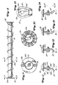
- Fig. 8 is a view of the cutter auger showing the helixes thereon.
- Fig. 9 is a sectional view through line 9-9 of Fig. 8.
- Fig. 10 is a sectional view taken on the line 10-10 of Fig. 8.
- Figs. 11, 12, 13 and 14 show the attachment of the teeth to the flighting of the cutting auger, according to the invention.
- Fig. 15 is a sectional view along
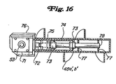
line 15 of Fig. 14. - Fig. 16 is a side view of the power auger assembly.
- Referring now to the drawings: in the illustrated embodiment a crop processor is shown generally at 10. The crop processor includes the auger cutter and the other operating elements of the crop processor. The crop processor is shown attached to a prime mover and second processor shown as a forage harvester 11. The
crop processor 10 includes a support frame 12 shown best in Fig. 7 comprising arear top rail 13 formed from a rectangular tube and havingend plates bottom front rail 15 and afront top rail 14 which are an integral part of the frame and are connected bysupport members 16 between the fronttop rail 14 and thebottom front rail 15. Theend plates bearing units holes 22 in theend plates conveyor auger bottoms 23, theconveyor cover 24 from rear to the top for theconveyor augers 27, theside plates 24a to close off the exit for the central discharge area. There is also shown thebaffle plate 25 in Fig. 7. Fig. 7 shows the support for the drive unit to drive the power discharge units. This plate is numbered 26. The open, generally central discharge area is designated as 30 and is seen very clearly as an open area in Fig. 7. - As seen in Figs. 2, 3 and 4, a pair of cutting augers shown generally at 31 and 32 extend between the
end plates enclosures helical flanges flanges end plates cutting augers teeth 37 to be further described are attached to and project around the peripheral edges of theflange plates unit 10 in the cutting and processing of standing crops. - In prior auger cutting devices plates have been used between the cutting augers and the conveying augers to guide material into the conveying auger. Such a cover plate is described in U.S. Patent No. 4,550,554,
Column 4,lines 48 through 55. Such a plate has previously permitted both crop accumulation on the plate and ejection forward of the crop material collected in the conveyor auger housing. - It has been found that the shape and locations of this plate is critical to proper operation of the processor. The upper edge of the baffle plate must be placed in close proximity to the cutting auger and the best operation has been with the plate being located not more than 1.27 cm (0.5 inches) from the teeth of the cutting auger, yet not impacting the teeth. The baffle plate must also be shaped between the radius of the cutting auger or the conveyor auger for best operation.
- A pair of ground
engaging rollers rollers bottom support member 16 byplates 42 which permit the pivoting about the center point of theroller 38 as shown in Fig. 6. The roller is attached to theplate 42 via bars 42a which are connected tohydraulic cylinders 39 which are connected to switch means 41 in such a manner that when theground engaging rollers cylinder 39 closing theswitch 41. This movesfront door 43 to the operating position and can inform the operator that the unit is on the ground. The height of cut is maintained by this roller switch mechanism acting in conjunction with thehydraulic cylinder 39. The tilt and selected cutting height of the processor can be set by the operator from the main control as the speed, crop conditions, and/or contour of the land changes. - There is a further important part of the processor which is shown in Fig. 6, the door or
front cover unit 43. Thisfront cover unit 43 is pivotally hinged about the uppermain frame 14 and is pivoted by controlling thecylinders 44. The height of thefront door unit 43 above the ground should be adjusted by the operator to ensure that the grass or material to be cut is bent forward the proper amount just prior to being hit by the teeth of the cutting auger. This height will vary depending upon the nature and density of the crop to be cut. - It has been found that in large standing crops such as corn where the material is not to be windrowed but to be fed to a second unit such as a forage harvester, and additional
crop moving auger 45 should be attached to the front of thedoor 43. This crop moving auger ensures that the crop enters the processor and is not lost to the sides as the processor moves through the crop. Thecrop moving auger 45 as shown in Fig. 3 has a plurality of smooth flightings attached to it. These flightings are helical flanges 46. These helical flanges may be variable and indeed different conditions may require different pitches per foot along the entire auger length. These flanges are wound to move the crop toward the center from each side. It may be necessary in order to determine the proper speed that thisauger 45 have variable speed drive. This auger therefore is driven by a hydraulic drive 47 which can be controlled from the cabin by the operator. This auger normally rotates at a much lower speed than the cutting auger. This speed can be controlled and has little relationship to the speed of the crop conveying auger but is closely related to the ground speed of the processor. - The front door must have an automatic control to ensure that during transport whenever the augers are rotating the front door is closed. This automatic door operation can be accomplished by either determining the pressure of the prime mover's hydraulic system with pressure switches or by monitoring the position of the tapered rollers. This latter method is shown in Fig. 6a where the upward movement of the
hydraulic cylinder 39 will cause operation of thelimit switch 41. Either roller can operate the door based upon whether or not the roller is in a down position. If eitherroller limit switch 41 to be operated and the door is returned to a predetermined operating position. If neither roller of the processor is in contact with the ground, the limit switches 41 are opened and door will automatically be lowered into the transport or safety closed position. - When processing corn or sorghum which is to be fed into a second crop processor, namely, a forage harvester, an entirely different set of problems arises and requires further novel features of this processor. Namely, the push augers or the feed augers 48 which are positioned in the
central discharge area 30. These augers may be installed as a removable unit or may be permanently installed in such area. The necessity to force-feed large quantities of material which have been cut by the crop processor into a second processor requires this plurality of feed augers 48. These augers can feed 3.66 m (12 feet) or more of crop material forcefully out of the crop processor into a relatively small exit area. These augers serve to compact the material and force the material under extreme pressure from the crop processor into whatever other processor or unit is required to finish the crop processing. The material enters from the side of the conveyingauger lower feed augers upper auger 50 acts to both compress the crop between theaugers - This feeding mechanism requires a novel header mounting which will be described more fully later, but one that ensures that the
feed augers auger 50 and movement rearwardly for discharge. The power feed augers 49a and 49b in operation are subjected to extreme lateral forces as the large mass of material is fed from the conveying augers into the discharge area. Normal auger mountings failed every time during experimental use and such failure was almost immediate. - The novel auger module was able to withstand all loads during development. The design shown is a modular unit though the entire auger assembly could be one unit. The auger assembly consists of flighting 49a'; a slightly heavier than the usual flighting of a conveyor auger, flighting
tube 49a,auger support plates 77 andauger support shaft 78. Acoupler 72 is used to transmit the necessary torque to the auger. Radial loading is absorbed bybearings 73. Aspacer 75, or a plurality of spacers may be used to transfer the thrust load to either or thegear box 71 andbearings 73. - Means such as pins not shown, may also be used to retain both bearing 73 and to lock
coupler 72 toshaft 78 thereby retaining the auger assembly in position. - The drive system for these augers consists of a T-shaped
gear box 52 attached to a chain box 57a which may contain an overload safety device which can be provided by an overload clutch, of any well known type not shown. Thelower feed augers shaft 53.Shaft 53 is carried inside of the main support frame 12 to provide protection from wrapping of material on the shaft. - In this mode of operation, i.e., heavy corn, or where the central discharge area is occupied by a large mass of solid material, provision should be made for releasing the air generated by the rotation of the cutting and conveying augers in the enclosed space.
- This air pressure should be released in order for the system to operate efficiently. The air pressure is released by providing screen means in the
top cover 24 and thesides 24a of the discharge opening. The means 24 and 24a are made of a suitably strong screen material which has approximately 50 percent openings and 50 percent material. The holes in the material should be small enough so that alfalfa leaves or small parts of oats will not pass through the holes and also provide that the conveyor and feed augers wipe over the screen. This wiping should ensure that the screen will be completely cleaned approximately every three revolutions of the conveyor auger. This provides for both the release of the air and the capture of all of the material. - The mounting system is best illustrated in Fig. 5. The mounting system for this crop processor requires that the head or first crop processor has the ability to tilt relative to the second processor. The controls for this tilt are located in the cab, allowing the operator to change the cutting height while moving. It also has been found necessary during tilting of the first processor to prevent any gaps forming between the output means of this processor and the input means to the power source or second processor. The mounting system must also provide means to limit movement of the terminal end of the feed augers away from the input side of the second processor. In addition, the header or first processor as has been previously mentioned must be able to flex up and down on either side with respect to the prime mover and also permit the rollers previously mentioned to travel over a rise in the ground on only one side without stressing the mounting system. The mounting system should be such that attachment and removal are easily accomplished.
- The mounting system is provided by having a
frame 55 attached to the chopper head or the second processor head bypins 56 at the four corners. In addition, there are twoplates 54 welded to the frame. These plates provide a U-shaped slot on each side of the discharge opening in the processor. The axis of rotation between this frame and the header of the second processor is such that it is centered around the upper corner of the lower frame member of the attached second processor. The force for rotation is provided by twocylinders 57 which is at thelower point 56. The movement of the cylinders is controlled from the cab and can forcefully tilt the header through the frame member and its connection to the lowersupport frame member 16. - In many instances the forage harvesters or the second crop harvesters have metal detectors in their chopping unit to stop the forage operation as soon as metal is detected. If metal is detected, the second processor ceases to operate and if material were continued to be fed from the first crop processor, then a jam would occur as there is no place for the cut material to go. In addition, because of the great pressures exerted by the power auger feed system against a fixed surface an intolerable plug would result. To prevent this plugging, a throw out coupler system has been utilized to protect and stop the power input to the second crop processor. The metal detection system is located in the second crop processor and if it senses metal it generates an electrical signal which stops the second crop processor operation. This same electrical signal is connected to the throw out coupler system in the first processor.
- The
power source 61 from the prime mover 11 is connected to thefirst gear box 58 of the crop processor bypto shaft 60. This will permit flexing and relative movement between the prime mover unit and the header or the first crop processor. A throw outcoupler system 59 is placed between thegear box 58 and thegear box 62 so that the power will immediately be cut by the throw out coupler when the power is cut to the feed system of the prime mover unit. - According to the invention, the
teeth 37 used on this crop processor are unique and are best described with reference to Figs. 11, 12, 13, 14 and 15. The teeth incorporate several features to give the teeth long operational life, impact resistance, versatility, etc. The tooth, of generally horse shoe configuration shown in Fig. 15 in plan view, includes a beveled surface 37a, ahole 37c for mounting the tooth and aflat surface 37b, and the other side isflat surface 37b'. A portion ofsurface 37b' and the bevel surface at the converging end has a layer of hardened material applied to makesurface 37b' the wear and self-sharpening characteristics of the tooth. The tooth is bent at approximately 45° in the direction of the bevel surface. The mounting system for this tooth provides for a plurality of mounting configurations as shown in Figs. 11, 12, 13 and 14. In Fig. 12, thetooth 37 is mounted bybolts 37d andnut 37e through thehole 37c in the tooth 37and theflighting 33a. The cuttingauger tube 32 is also shown. In each of these figures the tooth is viewed from the front as the tooth is ready to cut the crop material. The mounting bolts have an angle similar to the bevel 37a to provide a slope surface to prevent sticking of the cut material and reduce wear on the bolt. Thetooth 37 is designed with a symmetrical pattern. The symmetry results in two cutting edges on each tooth. When one edge is worn down the tooth may simply be reinstalled to a new position on either auger of the machine so that the second cutting edge can be used. - Another operational aspect of this invention is that the characteristics of this tooth can be mounted on the front side or the back side of the flighting as shown in Figs. 11, 12, 13 and 14. As shown in Figs. 12, 13 and 14 a lock washer 37f is used to maintain the tooth in a fixed position. This permits any fixed cutting angle to be established as desired due to crop, etc. The lock washer in Fig. 14 can be removed from the
bolt 37d to permit swinging of the teeth. The front side swinging mount as shown in Fig. 11 provides the most aggressive cutting action and is useful in most cutting situations. The tooth can also be mounted on the backside of the flange as shown in Figs. 12 and 14; however, in Fig. 12 it must be rigidly mounted. Backside mounting provides a less aggressive action and is utilized in handling tender material. Where the crop material is thicker and more rigid as in the case of corn, front mounting in preferred. - As noted, the present disclosure is based on a preferred embodiment of the invention. Features and advantages other than those specifically pointed out herein will occur to those versed in the art, as will many modifications in the preferred embodiment presented, all without departing from the scope of the invention, as defined by the claims.
Claims (2)
- A crop processors comprising :an auger (31, 32) having flighting (33, 33a) therearound;support means (17, 18, 19) for said auger (31, 32);drive means for rotating said auger (31, 32);teeth (37) for attachment to said flighting (33, 33a) on said auger (31, 32); andmeans (37d, 37e) for attaching said teeth (37) to said flighting (33, 33a),each of said teeth (37) including a metal base plate having a first surface (37b) and an opposite second surface (37b'), said metal base plate having a hole (37c) for attaching to said auger flighting (33, 33a) and bevels on a major portion (37a) of said first surface (37b), characterized in thatsaid metal base plate, when shown in plan view, is of essentially horse shoe shape, having a circular portion and converging side portion, the hole (37c) being toward the circular end of said metal base plate;said metal base plate being bent inwardly on the side of the first surface (37b), and the second surface (37b') of the metal base plate being hard surfaced only on the converging side portion (37b").
- A crop processor in accordance with claim 1, wherein said means for attachment of said teeth (37) to said flighting (33, 33a) is a bolt (37d) having an essentially conical head.
Applications Claiming Priority (3)
| Application Number | Priority Date | Filing Date | Title |
|---|---|---|---|
| US479321 | 1990-02-13 | ||
| US07/479,321 US5005342A (en) | 1990-02-13 | 1990-02-13 | Crop processor |
| EP90113193A EP0443079B1 (en) | 1990-02-13 | 1990-07-11 | Improved crop processor |
Related Parent Applications (2)
| Application Number | Title | Priority Date | Filing Date |
|---|---|---|---|
| EP90113193A Division EP0443079B1 (en) | 1990-02-13 | 1990-07-11 | Improved crop processor |
| EP90113193.8 Division | 1990-07-11 |
Publications (3)
| Publication Number | Publication Date |
|---|---|
| EP0784918A2 EP0784918A2 (en) | 1997-07-23 |
| EP0784918A3 EP0784918A3 (en) | 1997-10-15 |
| EP0784918B1 true EP0784918B1 (en) | 2002-01-02 |
Family
ID=23903536
Family Applications (2)
| Application Number | Title | Priority Date | Filing Date |
|---|---|---|---|
| EP90113193A Expired - Lifetime EP0443079B1 (en) | 1990-02-13 | 1990-07-11 | Improved crop processor |
| EP97106236A Expired - Lifetime EP0784918B1 (en) | 1990-02-13 | 1990-07-11 | Crop processor with improved auger cutter teeth |
Family Applications Before (1)
| Application Number | Title | Priority Date | Filing Date |
|---|---|---|---|
| EP90113193A Expired - Lifetime EP0443079B1 (en) | 1990-02-13 | 1990-07-11 | Improved crop processor |
Country Status (10)
| Country | Link |
|---|---|
| US (1) | US5005342A (en) |
| EP (2) | EP0443079B1 (en) |
| JP (1) | JPH0789785B2 (en) |
| CN (1) | CN1053989A (en) |
| AU (1) | AU627677B2 (en) |
| BR (1) | BR9005191A (en) |
| CA (1) | CA2019449C (en) |
| DE (2) | DE69033890T2 (en) |
| DK (1) | DK303390A (en) |
| ZA (1) | ZA905109B (en) |
Families Citing this family (40)
| Publication number | Priority date | Publication date | Assignee | Title |
|---|---|---|---|---|
| US5305586A (en) * | 1992-08-20 | 1994-04-26 | Lundahl Research, Inc. | Crop processor |
| US5309702A (en) * | 1992-08-20 | 1994-05-10 | Lundahl Research, Inc. | Cutting tooth |
| US5399307A (en) * | 1993-06-18 | 1995-03-21 | Dalton; Robert E. | Methods of compression molding two or more polytetrafluoroethylene resin layers |
| US6058688A (en) * | 1998-05-08 | 2000-05-09 | Deere & Company | Windrower specialty crop platform having right- and left-hand cantilevered augers located beneath a full-length center-feed auger |
| US6125617A (en) * | 1998-09-15 | 2000-10-03 | Gehl Company | Cut crop processing mechanism for a forage harvester incorporating a pivotable auger |
| DE19918551B4 (en) | 1999-04-23 | 2015-04-02 | Deere & Company | harvester |
| US6561896B1 (en) | 2000-05-22 | 2003-05-13 | David M. Lauer | Auger for combine header |
| DE10130647A1 (en) * | 2001-06-27 | 2003-01-16 | Claas Selbstfahr Erntemasch | Support wheel arrangement for agricultural harvester etc. with wheel located in support frame, in working connection with harvester and holder device for agricultural tool |
| US6705067B2 (en) | 2002-07-16 | 2004-03-16 | Case Corporation | Feed conveyor/rock trap and header drive for an agricultural combine |
| US6877303B2 (en) * | 2002-07-19 | 2005-04-12 | Cnh America Llc | Stub auger support used in pickup |
| US6679042B1 (en) | 2002-11-12 | 2004-01-20 | Acco Corporation | Infeed cutter baler having increased throughput |
| US7277785B2 (en) * | 2005-07-15 | 2007-10-02 | Cnh America Llc | Apparatus and method to calibrate a draper on an agricultural header on an agricultural windrower |
| US7483780B2 (en) * | 2005-07-15 | 2009-01-27 | Cnh America Llc | Apparatus and method to calibrate the reel of an agricultural windrower |
| US20080276590A1 (en) | 2006-02-10 | 2008-11-13 | Agco Corporation | Flexible draper and cutter bar with tilt arm for cutterbar drive |
| US20070193243A1 (en) | 2006-02-10 | 2007-08-23 | Schmidt James R | Combine Harvester Draper Header Having Flexible Cutterbar |
| US20080271426A1 (en) | 2006-02-10 | 2008-11-06 | Agco Corporation | Draper belt with crop-retaining rib |
| US20080066316A1 (en) * | 2006-09-15 | 2008-03-20 | Tommy Lee Schwab | Corn stripper |
| US20090266044A1 (en) | 2008-04-25 | 2009-10-29 | Coers Bruce A | Integrated draper belt support and skid shoe in an agricultural harvesting machine |
| US20090277145A1 (en) | 2008-05-09 | 2009-11-12 | Agco Corporation | Header height control system with multiple potentiometer input |
| EP2315514B1 (en) | 2008-05-09 | 2012-04-25 | Agco Corporation | Adjustable cutterbar travel range for a flexible cutterbar header |
| US7921627B2 (en) | 2008-05-09 | 2011-04-12 | Agco Corporation | Interlocking belt guards for a draper header |
| ATE538637T1 (en) | 2008-05-09 | 2012-01-15 | Agco Corp | CENTER HARVEST GUIDE DEVICE FOR CONVEYOR BELT ATTACHMENT |
| US20090277144A1 (en) | 2008-05-09 | 2009-11-12 | Agco Corporation | Spring flotation for center deck of draper header |
| US7886511B2 (en) | 2008-05-09 | 2011-02-15 | Agco Corporation | Draper head with flexible cutterbar having rigid center section |
| US20090277148A1 (en) | 2008-05-09 | 2009-11-12 | Agco Corporation | Flexible draper and cutter bar having shiftable crop divider with deflector |
| DE102010021133A1 (en) * | 2010-05-21 | 2011-11-24 | Claas Selbstfahrende Erntemaschinen Gmbh | Agricultural working machine with header |
| US8205421B2 (en) | 2010-06-16 | 2012-06-26 | Agco Corporation | Belt guard crop dam for flexible draper header |
| US7958711B1 (en) | 2010-06-16 | 2011-06-14 | Agco Corporation | Crop deflector for ends of draper belt of flexible draper header |
| US8863489B2 (en) | 2011-03-30 | 2014-10-21 | H & S Manufacturing Co., Inc. | Tine drive cam for windrow merger |
| US8479483B1 (en) | 2011-12-27 | 2013-07-09 | Agco Corporation | Flexible draper head providing reduced crop residue accumulation |
| US9425124B2 (en) | 2012-02-02 | 2016-08-23 | International Business Machines Corporation | Compliant pin fin heat sink and methods |
| US8806844B2 (en) * | 2012-02-24 | 2014-08-19 | Dom, L.L.C. | Flail motor head attachment |
| CN103359419A (en) * | 2012-03-29 | 2013-10-23 | 张有才 | Feed transfer tank |
| CN104348850B (en) * | 2013-07-25 | 2017-10-20 | 凌群电脑股份有限公司 | The system for accessing cloud database data using saturating logical technology |
| US9814181B2 (en) * | 2015-05-08 | 2017-11-14 | Cnh Industrial America Llc | Drive mechanism for augers of an agricultural harvester header |
| US10729070B2 (en) * | 2017-01-25 | 2020-08-04 | Paul Howard Nyboer | Mulching apparatus for a lawnmower |
| CN106993446B (en) * | 2017-04-18 | 2019-08-23 | 安徽农业大学 | A kind of crushing of efficient straw, which is urged, rotten buries chopper |
| CN109729767B (en) * | 2019-02-13 | 2024-03-08 | 黑龙江省农业科学院土壤肥料与环境资源研究所 | Combined type straw crushing and centralized deep-buried plow |
| EP3909413A1 (en) * | 2020-05-14 | 2021-11-17 | Maschinenfabrik Bermatingen GmbH & Co. KG | Mowing or mulching device and cutting tool for same |
| US11266071B1 (en) | 2020-08-27 | 2022-03-08 | H & S Manufacturing Co., Inc. | Windrow merger with active weight transfer system |
Family Cites Families (27)
| Publication number | Priority date | Publication date | Assignee | Title |
|---|---|---|---|---|
| US2517390A (en) * | 1948-12-22 | 1950-08-01 | Int Harvester Co | Auxiliary cutter for harvester platforms |
| US2634567A (en) * | 1950-08-29 | 1953-04-14 | John J Huitema | Stalk shredder |
| US2758435A (en) * | 1954-06-01 | 1956-08-14 | Vernon J Lundell | Crop gathering and chopping device |
| US2725704A (en) * | 1954-12-17 | 1955-12-06 | Deere Mfg Co | Forage harvester having stalk directing means |
| US2863023A (en) * | 1956-01-27 | 1958-12-02 | Gen Electric | Bimetallic strip thermally responsive device |
| US2946170A (en) * | 1957-11-18 | 1960-07-26 | Deere & Co | Conveyor means for corn harvester |
| US3073100A (en) * | 1960-08-15 | 1963-01-15 | Richard O Kingsley | Mower having helical cutter blade |
| US3319408A (en) * | 1964-08-12 | 1967-05-16 | Martin J Landwehr | Reels for farm machinery |
| FR1415334A (en) * | 1964-12-01 | 1965-10-22 | Int Harvester Co | Windrower having a platform comprising two augers |
| NL6515224A (en) * | 1965-11-24 | 1967-05-25 | ||
| DE1901155A1 (en) * | 1969-01-10 | 1970-10-22 | Fahr Ag Maschf | Harvester |
| US3862539A (en) * | 1973-07-27 | 1975-01-28 | J L Stevens | Ground clearing attachment for tractors |
| US3919830A (en) * | 1973-11-26 | 1975-11-18 | Jerome J Gerber | Row crop attachment for forage harvesters |
| US4251980A (en) * | 1979-03-26 | 1981-02-24 | Miller Kent A | Cornstalk harvesting and windrow attachment for a corn picker header |
| DE2919123A1 (en) * | 1979-05-11 | 1980-11-20 | Kloeckner Humboldt Deutz Ag | ELEVATOR GUIDE FOR THE ELEVATIBLE WORK TOOL OF AN AGRICULTURAL HARVESTING MACHINE |
| FR2466946A1 (en) * | 1979-10-12 | 1981-04-17 | Dekerchove Marcel | Engine-driven wheeled lawn mower - has knives on radial arms on spindles parallel to horizontal shaft |
| US4414792A (en) * | 1982-03-30 | 1983-11-15 | Blackwelders | Height control for agricultural machine |
| DD210514A3 (en) * | 1982-06-03 | 1984-06-13 | Fortschritt Veb K | FEEDING DEVICE FOR AXIAL FLOW RAIL |
| US4550554A (en) * | 1984-01-03 | 1985-11-05 | Ezra C. Lundahl, Inc. | Crop processor |
| IT8463353V0 (en) * | 1984-09-27 | 1984-09-27 | Storti Ottorino | CUTTING ELEMENTS APPLICABLE ON CUTTING AND CONVEYING SCREWS IN PARTICULAR WAY OF SILAMED FILAMENT MATERIALS. |
| US4612757A (en) * | 1985-04-12 | 1986-09-23 | Sperry Corporation | Combine header attitude control mechanism |
| AU548518B3 (en) * | 1985-10-28 | 1985-11-28 | Chamberlain John Deere Pty. Ltd. | Improvements in harvesting cutting platforms |
| JPS62118804A (en) * | 1985-11-20 | 1987-05-30 | 小橋工業株式会社 | Plowing and reaping apparatus |
| US4776153A (en) * | 1986-02-27 | 1988-10-11 | Deere & Company | Automatic height control for a laterally pivoted harvester header |
| ATE130161T1 (en) * | 1988-02-08 | 1995-12-15 | Wieneke Franz | ROLLER MOWER. |
| DK158869C (en) * | 1988-02-24 | 1995-12-04 | Spragelse Maskinfabrik As | Appliance for mowing grass and similar crops |
| IT215694Z2 (en) * | 1988-07-29 | 1990-10-24 | Seko Spa | WHEEL MIXER DISPENSER DISPENSER PERFECTLY PARTICULARLY FOR DISPENSING SHREDDING MIXING AND DISTRIBUTION OF BALES PRISMATIC CYLINDRICAL GIANTS FORAGE AND STRAW OR GRASS SILVES. |
-
1990
- 1990-02-13 US US07/479,321 patent/US5005342A/en not_active Expired - Fee Related
- 1990-06-20 CA CA002019449A patent/CA2019449C/en not_active Expired - Fee Related
- 1990-06-29 ZA ZA905109A patent/ZA905109B/en unknown
- 1990-07-02 AU AU58096/90A patent/AU627677B2/en not_active Ceased
- 1990-07-11 DE DE69033890T patent/DE69033890T2/en not_active Expired - Fee Related
- 1990-07-11 DE DE69033341T patent/DE69033341T2/en not_active Expired - Fee Related
- 1990-07-11 EP EP90113193A patent/EP0443079B1/en not_active Expired - Lifetime
- 1990-07-11 EP EP97106236A patent/EP0784918B1/en not_active Expired - Lifetime
- 1990-08-18 JP JP2218013A patent/JPH0789785B2/en not_active Expired - Lifetime
- 1990-10-16 BR BR909005191A patent/BR9005191A/en not_active IP Right Cessation
- 1990-12-21 DK DK303390A patent/DK303390A/en not_active Application Discontinuation
-
1991
- 1991-01-16 CN CN91100374A patent/CN1053989A/en active Pending
Also Published As
| Publication number | Publication date |
|---|---|
| CN1053989A (en) | 1991-08-28 |
| AU627677B2 (en) | 1992-08-27 |
| CA2019449A1 (en) | 1991-08-13 |
| DE69033341T2 (en) | 2000-06-08 |
| DK303390A (en) | 1991-08-14 |
| DK303390D0 (en) | 1990-12-21 |
| AU5809690A (en) | 1991-08-15 |
| DE69033341D1 (en) | 1999-12-09 |
| EP0784918A2 (en) | 1997-07-23 |
| ZA905109B (en) | 1991-04-24 |
| DE69033890T2 (en) | 2002-09-05 |
| JPH03240408A (en) | 1991-10-25 |
| EP0784918A3 (en) | 1997-10-15 |
| EP0443079A3 (en) | 1995-01-11 |
| JPH0789785B2 (en) | 1995-10-04 |
| DE69033890D1 (en) | 2002-02-07 |
| CA2019449C (en) | 1999-10-26 |
| US5005342A (en) | 1991-04-09 |
| EP0443079A2 (en) | 1991-08-28 |
| BR9005191A (en) | 1991-11-19 |
| EP0443079B1 (en) | 1999-11-03 |
Similar Documents
| Publication | Publication Date | Title |
|---|---|---|
| EP0784918B1 (en) | Crop processor with improved auger cutter teeth | |
| US3971390A (en) | Stone trap for threshing and separating machine | |
| US6430904B1 (en) | Platform auger torque sensing brake activation | |
| CA2306309C (en) | Harvesting machine | |
| US5661961A (en) | Crop processor for round hay balers | |
| JPH09275755A (en) | Conveyor for agricultural baler | |
| EP0244977B1 (en) | Bale shredder | |
| EP2710881B1 (en) | Distributor machine | |
| US4033518A (en) | Forage harvester | |
| US4657029A (en) | Stone trap for a combine harvester | |
| EP0803181B1 (en) | Crop processor apparatus for forage harvester | |
| US5305586A (en) | Crop processor | |
| US6131837A (en) | Segmented crop processor roll for forage harvester | |
| US6685120B2 (en) | Hay bale separating apparatus and method | |
| WO2019053738A1 (en) | A self propelled track type axial flow combine harvester | |
| US4078734A (en) | Drive arrangement for field choppers | |
| US5626298A (en) | Tub grinder with rear discharge hammer mill and angled shear plates | |
| US4003191A (en) | Barrier means in a combine harvesting header | |
| US6431480B1 (en) | Square bale processor | |
| EP2111739B1 (en) | Combine harvester control | |
| EP1964461B1 (en) | Combine harvester power management control | |
| US4506840A (en) | Baffle means for forage harvesters | |
| RU2177682C2 (en) | Pneumatic grain combine | |
| GB2096453A (en) | Straw chopper and spreader assembly | |
| EP0498639B1 (en) | An apparatus for washing or chopping or mixing or dispensing material |
Legal Events
| Date | Code | Title | Description |
|---|---|---|---|
| PUAI | Public reference made under article 153(3) epc to a published international application that has entered the european phase |
Free format text: ORIGINAL CODE: 0009012 |
|
| AC | Divisional application: reference to earlier application |
Ref document number: 443079 Country of ref document: EP |
|
| AK | Designated contracting states |
Kind code of ref document: A2 Designated state(s): BE DE ES FR GB IT SE |
|
| PUAL | Search report despatched |
Free format text: ORIGINAL CODE: 0009013 |
|
| AK | Designated contracting states |
Kind code of ref document: A3 Designated state(s): BE DE ES FR GB IT SE |
|
| 17P | Request for examination filed |
Effective date: 19980408 |
|
| 17Q | First examination report despatched |
Effective date: 20000427 |
|
| GRAG | Despatch of communication of intention to grant |
Free format text: ORIGINAL CODE: EPIDOS AGRA |
|
| GRAG | Despatch of communication of intention to grant |
Free format text: ORIGINAL CODE: EPIDOS AGRA |
|
| GRAH | Despatch of communication of intention to grant a patent |
Free format text: ORIGINAL CODE: EPIDOS IGRA |
|
| GRAH | Despatch of communication of intention to grant a patent |
Free format text: ORIGINAL CODE: EPIDOS IGRA |
|
| GRAA | (expected) grant |
Free format text: ORIGINAL CODE: 0009210 |
|
| REG | Reference to a national code |
Ref country code: GB Ref legal event code: IF02 |
|
| AC | Divisional application: reference to earlier application |
Ref document number: 443079 Country of ref document: EP |
|
| AK | Designated contracting states |
Kind code of ref document: B1 Designated state(s): BE DE ES FR GB IT SE |
|
| PG25 | Lapsed in a contracting state [announced via postgrant information from national office to epo] |
Ref country code: IT Free format text: LAPSE BECAUSE OF FAILURE TO SUBMIT A TRANSLATION OF THE DESCRIPTION OR TO PAY THE FEE WITHIN THE PRE;WARNING: LAPSES OF ITALIAN PATENTS WITH EFFECTIVE DATE BEFORE 2007 MAY HAVE OCCURRED AT ANY TIME BEFORE 2007. THE CORRECT EFFECTIVE DATE MAY BE DIFFERENT FROM THE ONE RECORDED.SCRIBED TIME-LIMIT Effective date: 20020102 Ref country code: BE Free format text: LAPSE BECAUSE OF FAILURE TO SUBMIT A TRANSLATION OF THE DESCRIPTION OR TO PAY THE FEE WITHIN THE PRESCRIBED TIME-LIMIT Effective date: 20020102 |
|
| REF | Corresponds to: |
Ref document number: 69033890 Country of ref document: DE Date of ref document: 20020207 |
|
| PG25 | Lapsed in a contracting state [announced via postgrant information from national office to epo] |
Ref country code: SE Free format text: LAPSE BECAUSE OF FAILURE TO SUBMIT A TRANSLATION OF THE DESCRIPTION OR TO PAY THE FEE WITHIN THE PRESCRIBED TIME-LIMIT Effective date: 20020402 |
|
| ET | Fr: translation filed | ||
| PGFP | Annual fee paid to national office [announced via postgrant information from national office to epo] |
Ref country code: GB Payment date: 20020704 Year of fee payment: 13 |
|
| PG25 | Lapsed in a contracting state [announced via postgrant information from national office to epo] |
Ref country code: ES Free format text: LAPSE BECAUSE OF FAILURE TO SUBMIT A TRANSLATION OF THE DESCRIPTION OR TO PAY THE FEE WITHIN THE PRESCRIBED TIME-LIMIT Effective date: 20020730 |
|
| PLBE | No opposition filed within time limit |
Free format text: ORIGINAL CODE: 0009261 |
|
| STAA | Information on the status of an ep patent application or granted ep patent |
Free format text: STATUS: NO OPPOSITION FILED WITHIN TIME LIMIT |
|
| 26N | No opposition filed | ||
| PG25 | Lapsed in a contracting state [announced via postgrant information from national office to epo] |
Ref country code: DE Free format text: LAPSE BECAUSE OF NON-PAYMENT OF DUE FEES Effective date: 20030201 |
|
| PG25 | Lapsed in a contracting state [announced via postgrant information from national office to epo] |
Ref country code: FR Free format text: LAPSE BECAUSE OF NON-PAYMENT OF DUE FEES Effective date: 20030331 |
|
| REG | Reference to a national code |
Ref country code: FR Ref legal event code: ST |
|
| PG25 | Lapsed in a contracting state [announced via postgrant information from national office to epo] |
Ref country code: GB Free format text: LAPSE BECAUSE OF NON-PAYMENT OF DUE FEES Effective date: 20030711 |
|
| GBPC | Gb: european patent ceased through non-payment of renewal fee |
Effective date: 20030711 |