EP0784202A2 - Phase-contrast X-ray CT apparatus - Google Patents
Phase-contrast X-ray CT apparatus Download PDFInfo
- Publication number
- EP0784202A2 EP0784202A2 EP96120999A EP96120999A EP0784202A2 EP 0784202 A2 EP0784202 A2 EP 0784202A2 EP 96120999 A EP96120999 A EP 96120999A EP 96120999 A EP96120999 A EP 96120999A EP 0784202 A2 EP0784202 A2 EP 0784202A2
- Authority
- EP
- European Patent Office
- Prior art keywords
- ray
- crystal
- phase
- contrast
- diffraction
- Prior art date
- Legal status (The legal status is an assumption and is not a legal conclusion. Google has not performed a legal analysis and makes no representation as to the accuracy of the status listed.)
- Granted
Links
- 239000013078 crystal Substances 0.000 claims abstract description 63
- 230000010363 phase shift Effects 0.000 claims description 17
- 230000007246 mechanism Effects 0.000 claims description 3
- 238000000034 method Methods 0.000 description 27
- 238000010521 absorption reaction Methods 0.000 description 7
- 238000003384 imaging method Methods 0.000 description 6
- 230000035945 sensitivity Effects 0.000 description 6
- 238000010276 construction Methods 0.000 description 5
- 230000006870 function Effects 0.000 description 5
- 238000005259 measurement Methods 0.000 description 5
- 239000002872 contrast media Substances 0.000 description 3
- 238000003745 diagnosis Methods 0.000 description 3
- 238000010586 diagram Methods 0.000 description 3
- 230000008859 change Effects 0.000 description 2
- 238000003780 insertion Methods 0.000 description 2
- 230000037431 insertion Effects 0.000 description 2
- 230000003287 optical effect Effects 0.000 description 2
- 230000008569 process Effects 0.000 description 2
- 210000004872 soft tissue Anatomy 0.000 description 2
- 206010028980 Neoplasm Diseases 0.000 description 1
- 230000005540 biological transmission Effects 0.000 description 1
- 210000004204 blood vessel Anatomy 0.000 description 1
- 230000002860 competitive effect Effects 0.000 description 1
- 238000002591 computed tomography Methods 0.000 description 1
- 238000007796 conventional method Methods 0.000 description 1
- 230000001066 destructive effect Effects 0.000 description 1
- 238000001514 detection method Methods 0.000 description 1
- 238000006073 displacement reaction Methods 0.000 description 1
- 230000006872 improvement Effects 0.000 description 1
- 238000007689 inspection Methods 0.000 description 1
- 230000003993 interaction Effects 0.000 description 1
- 239000011368 organic material Substances 0.000 description 1
- 239000005416 organic matter Substances 0.000 description 1
- 229910052710 silicon Inorganic materials 0.000 description 1
- 239000010703 silicon Substances 0.000 description 1
- 230000001360 synchronised effect Effects 0.000 description 1
- 230000005469 synchrotron radiation Effects 0.000 description 1
- 210000001519 tissue Anatomy 0.000 description 1
- 238000003325 tomography Methods 0.000 description 1
- 238000002834 transmittance Methods 0.000 description 1
- 210000001835 viscera Anatomy 0.000 description 1
Images


Classifications
-
- A—HUMAN NECESSITIES
- A61—MEDICAL OR VETERINARY SCIENCE; HYGIENE
- A61B—DIAGNOSIS; SURGERY; IDENTIFICATION
- A61B6/00—Apparatus or devices for radiation diagnosis; Apparatus or devices for radiation diagnosis combined with radiation therapy equipment
- A61B6/48—Diagnostic techniques
- A61B6/484—Diagnostic techniques involving phase contrast X-ray imaging
-
- G—PHYSICS
- G01—MEASURING; TESTING
- G01N—INVESTIGATING OR ANALYSING MATERIALS BY DETERMINING THEIR CHEMICAL OR PHYSICAL PROPERTIES
- G01N23/00—Investigating or analysing materials by the use of wave or particle radiation, e.g. X-rays or neutrons, not covered by groups G01N3/00 – G01N17/00, G01N21/00 or G01N22/00
- G01N23/02—Investigating or analysing materials by the use of wave or particle radiation, e.g. X-rays or neutrons, not covered by groups G01N3/00 – G01N17/00, G01N21/00 or G01N22/00 by transmitting the radiation through the material
- G01N23/04—Investigating or analysing materials by the use of wave or particle radiation, e.g. X-rays or neutrons, not covered by groups G01N3/00 – G01N17/00, G01N21/00 or G01N22/00 by transmitting the radiation through the material and forming images of the material
- G01N23/046—Investigating or analysing materials by the use of wave or particle radiation, e.g. X-rays or neutrons, not covered by groups G01N3/00 – G01N17/00, G01N21/00 or G01N22/00 by transmitting the radiation through the material and forming images of the material using tomography, e.g. computed tomography [CT]
-
- A—HUMAN NECESSITIES
- A61—MEDICAL OR VETERINARY SCIENCE; HYGIENE
- A61B—DIAGNOSIS; SURGERY; IDENTIFICATION
- A61B6/00—Apparatus or devices for radiation diagnosis; Apparatus or devices for radiation diagnosis combined with radiation therapy equipment
- A61B6/40—Arrangements for generating radiation specially adapted for radiation diagnosis
- A61B6/4064—Arrangements for generating radiation specially adapted for radiation diagnosis specially adapted for producing a particular type of beam
- A61B6/4092—Arrangements for generating radiation specially adapted for radiation diagnosis specially adapted for producing a particular type of beam for producing synchrotron radiation
-
- G—PHYSICS
- G01—MEASURING; TESTING
- G01N—INVESTIGATING OR ANALYSING MATERIALS BY DETERMINING THEIR CHEMICAL OR PHYSICAL PROPERTIES
- G01N2223/00—Investigating materials by wave or particle radiation
- G01N2223/40—Imaging
- G01N2223/419—Imaging computed tomograph
-
- G—PHYSICS
- G21—NUCLEAR PHYSICS; NUCLEAR ENGINEERING
- G21K—TECHNIQUES FOR HANDLING PARTICLES OR IONISING RADIATION NOT OTHERWISE PROVIDED FOR; IRRADIATION DEVICES; GAMMA RAY OR X-RAY MICROSCOPES
- G21K2207/00—Particular details of imaging devices or methods using ionizing electromagnetic radiation such as X-rays or gamma rays
- G21K2207/005—Methods and devices obtaining contrast from non-absorbing interaction of the radiation with matter, e.g. phase contrast
Definitions
- the present invention relates to non-destructive and three-dimensional observation of the inside of an object using X-rays, and more particularly to such observation for an object made of light elements to which the conventional method relying on absorption contrast has a poor sensitivity.
- the present invention is applicable to inspection instruments for organic materials or medical diagnosis apparatuses.
- the contrast of an obtained image depends upon the degree of absorption of X-rays by an object. Namely, if there is a region where heavy elements with high X-ray absorptance are dense, that portion exhibits a low transmittance and can be caught as a shadow in a image. Reversely, an organic matter made of light elements is transparent to X-rays and is therefore difficult to obtain an image contrast. Accordingly, there is employed a method in which the contrast is emphasized by injecting heavy elements as a contrast agent in order to observe biological soft tissues (such as internal organs, tumors, or blood vessels), for example, when an X-ray cross section image for medical diagnosis is to be acquired.
- biological soft tissues such as internal organs, tumors, or blood vessels
- phase-contrast imaging method enables observation with an excellent sensitivity which is one-thousand times as high as that in the conventional imaging method. This shows that biological soft tissues can be observed without being subjected to a specific contrasting process. This is experimentally testified. Also, even if a contrast agent is used, the choice of a wider variety of contrast agents and contrasting techniques is possible. This facilitates to cope with specified purposes such as function imaging.
- phase-contrast X-ray CT apparatus in which phase contrast is introduced to the X-ray CT enabling three-dimensional observation.
- the system construction thereof is disclosed by U. S. Patent No. 5,173,928 to A. Momose et al., and the examples of observation of biological tissues are disclosed by A. Momose, et al., ReV. Sci. Instrum. 66 (1995) 1434.
- an X-ray interferometer is used to reconstruct an image in a virtual cross section from interference patterns.
- the examples of observation are shown for an object having a diameter of several millimeters.
- the disclosed technique reaches no practisation to medical diagnosis.
- An object of the present invention is to provide a phase-contrast X-ray CT with a simple system which uses no X-ray interferometer.
- the above-mentioned system using the X-ray interferometer has a problem (1) that in order to ensure coherency, the energy band of an X-ray beam must be narrowed to obtain a high monochromaticity and hence a bright light source such as synchrotron radiation must be used, a problem (2) that a precision optical system is required and it is therefore difficult to handle the system, and a problem (3) that a technique for ensuring a wide field of view counterbalancing the practical use is not established.
- the X-ray CT based on phase contrast requires the phase distribution of X-rays as input data.
- the phase distribution is acquired by an operation from interference patterns.
- no X-ray interferometer is used and the phase distribution is determined by the following method.
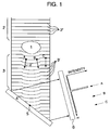
- an object 1 is irradiated with X-rays 2. It is assumed that the object 1 does not exhibit strong X-ray absorption (Image contrast is not created from absorption.) and transmitted X-rays 3 are obtained. It is also assumed that due to a phase shift caused by the object 1, the wavefront 2' of X-rays 2 (herein assumed as a plane wave, for simplicity) changes, as shown by the wavefront 3' of X-rays 3. Since the phase shift ⁇ (x) corresponds to the amount of change in wavefront form, the measurement of the phase shift ⁇ (x) corresponds to the measurement of the wavefront form. The following discussion will be made with an attention to the wavefront form on an x-axis for simplicity but will be expanded to a discussion on an x-y plane later on.
- the wavefront form is determined from an interference pattern generated by superimposing reference X-rays on X-rays transmitted through an object.
- an analyzer crystal 4 (see Fig. 1) is used to determine the wavefront form. Since an X-ray beam propagates in a direction normal to the wavefront thereof, a bend of the wavefront as shown in Fig. 1 may be understood as a change in propagation direction by the refraction of the beam. In the case of Fig.
- the propagation direction is delicately different at points A, B and C in accordance with the gradients of the wavefront.
- the analyzer crystal 4 is set so that an incidence angle for X-rays at the point A satisfies the Bragg diffraction condition. It is also assumed that the diffraction index of the analyzer crystal 4 is selected to provide a sufficiently narrow diffraction angle width and X-rays at the points B and C are not reflected by the analyzer crystal 4. In this case, only X-rays at the point A and X-rays substantially parallel thereto will be detected at the position of an X-ray image sensor 6. Namely, the analyzer crystal 4 has a function of selecting only a certain specified gradient portion of the wavefront 3'.
- phase distribution is determined as follows.
- the distribution of refraction angles is determined in such a manner that the analyzer crystal 4 is adapted to rotate around a certain rotation axis 5 at a high precision to record the diffraction intensity by the X-ray image sensor 6 plural times while changing the setting angle of the analyzer crystal 4 and the setting angle providing the maximum diffraction intensity is examined for each pixel.
- equation (2) a phase distribution is determined by integrating the obtained diffraction distribution. Also, it is possible to determine the zero point of ⁇ at a portion where there is no object in the image.
- the blur of the image caused by this refraction is several-ten ⁇ m even if a distance between the object and the X-ray image sensor is of order 1 m. Accordingly, if image observation with a more coarse spatial resolution than that is premised, there is no problem.
- the refraction angles in the two directions can be written, respectively, as Namely, are also satisfied. Accordingly, that at least one of ⁇ x and ⁇ y is known, suffices in order to determine ⁇ . Therefore, the analyzer crystal 4 may be scanned in either x-axis direction or y-axis direction. Now assume that the rotation axis of the analyzer crystal 4 is parallel to the y-axis and the refraction angle in the x-axis direction is examined.
- the present invention provides a merit that there is not needed an X-ray interferometer which is difficult to fabricate and handle, a merit that a thick X-ray beam can be used, thereby making it possible to ensure a wide field of view, and a merit that it is possible to structure a relatively bright optical system. Namely, the present has features which are advantageous when viewed from medical applications.
- the precision of phase determination depends upon the precision of refraction angle determination.
- the refraction angle of order 0.01 seconds is regarded as being a detection limit in the present invention. If an X-ray interferometer is used so that a beam having a similar refraction angle is subjected to interference with a reference X-ray beam, interference fringes are generated at the intervals of about 2 mm with X-rays of about 1 ⁇ . Even in the case where the refraction is more gentle, the interference fringes can be detected easily since the intervals of interference fringes are expanded. Namely, it can be said that for weak refraction, the use of the X-ray interferometer offers a high sensitivity rather than not.
- the technique according to the present invention can be regarded as an invention to obtain image in a sensitivity region which is intermediate between those of the conventional X-ray CT relying on absorption contrast and the phase-contrast X-ray CT using the X-ray interferometer.
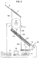
- Fig. 2 shows the construction of a first embodiment of the present invention.
- a crystal 9 cut from a good-quality perfect crystal ingot such as silicon is irradiated with an X-ray beam 8 obtained from an X-ray source 7.
- X-rays with a specified energy band satisfying the diffraction condition for a lattice plane 9' (see Fig. 3) inclined with respect to the surface of the crystal 9 generate a diffracted beam 10a.
- a feature as shown in Fig. 3 is known about the asymmetrical reflection of X-rays by the crystal. Namely, provided that the crystal lattice plane 9' of the crystal 9 is inclined by an angle ⁇ with respect to the crystal surface, as shown in Fig.
- the crystal 9 has not only a monochromatizing function of limiting the energy band width of the diffracted beam but also a function of enlarging the cross section of the beam and a function of collimating the diffracted beam (or approximating it to a plane wave).
- the analyzer crystal 11 utilizes asymmetrical diffraction as in the crystal 9 but has two reflection faces (11a and 11b) in an monolithic block. Also, the diffraction faces of the crystal 9 and the analyzer 11 are approximately parallel to each other.
- the beam is diffracted by the crystal 11b again (in a manner similar to that by the crystal 9) for restoration to the original beam width.
- the crystal 11 is fixed on a rotation table 12 and is rotatable, around a point 13 taken as a supporting point at a high precision, by a shaft 19 which a parallel displacement mechanism 18 using a linear motor, piezoelectric element or the like pushes.
- a beam 10d passed through the analyzer crystal 11 is detected by the X-ray image sensor 6 and the detected data (or diffraction intensity) is stored into an image memory 14 each time the analyzer crystal 11 is set to a specified angle.
- the setting angle of the analyzer crystal 11 providing the maximum intensity is determined for each pixel of the X-ray image sensor 6 and ⁇ (x) is determined in accordance with equation (4). Since the integrated form of ⁇ x) is a phase distribution image ⁇ (x), the image processor 16 can determine ⁇ x (x) by operation. (The x-axis and y-axis are defined as shown in Fig. 2.)
- the phase can be determined in a plurality of projection directions.
- the rotation of the object 1 and the rotation of the analyzer crystal 11 are made using a controller 15 which can be driven in synchronism with the image processor 16.
- An equivalent scan can also be performed by rotating the X-ray source 7, the crystal 9, the analyzer crystal 11 and the X-ray image sensor 6 around the axis 20 in a synchronous manner with the object being kept stationary.
- a phase distribution image in each projection direction is acquired.
- a phase-contrast X-ray CT image can be reconstructed by inputting the acquired data to a general X-ray CT algorithm.
- the X-ray image sensor 6 is a two-dimensional sensor, three-dimensional observation becomes possible since CT images in a series of plural planes parallel to the drawing sheet surface can be reconstructed in accordance with the above method.
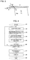
- Fig. 4 shows a flow chart of a series of measurement procedures.
- the flow starts from step 41.
- the analyzer is scanned (step 42), a refraction angle distribution ⁇ is determined (step 43), a phase shift distribution ⁇ is calculated (step 44) and the object is rotated by one step (step 45).
- step 46 the judgement is made as to whether or not the total rotation angle of the object is 180°. If the result of judgement in step 46 is "NO”, the flow returns to step 42. If the result of judgement in step 46 is "YES", a CT image is reconstructed (step 47) and displayed (step 48). The series of measurement procedures are completed by step 49.
- the present invention utilizes the bend of X-rays by refraction, approximation is assumed so that image blur caused by the bend is substantially negligible. Accordingly, the object is scanned by 180° and data of the remaining half round can use an inverted version of data of the first half round. Of course, if it does not matter that the scanning time is doubled, the scan over 360° may be conducted having a preference for the improvement of image quality.
- the beam 10a is a plane wave strictly. Accordingly, it is necessary to examine the initial wavefront form (or initial phase value) of the beam 10a by scanning the analyzer 11 beforehand in a state in which there is no object.
- a phase shift caused by an object corresponds to an amount by which a wavefront form determined with the object inserted changes from the initial wavefront form.
- Flow charts (of only the corresponding portions) in the respective cases are shown in Figs. 5A and 5B.
- the analyzer is scanned (step 61), a refraction angle distribution ⁇ O is determined (step 62) and an object is inserted (step 63). Thereafter, the object is scanned by the analyzer (step 64), a refraction angle distribution ⁇ S is determined (step 65), ⁇ S - ⁇ O is determined (step 66) and a phase shift distribution ⁇ is calculated (step 67).
- the used analyzer crystal has the monolithic configuration of two surfaces which are inclined with respect to a crystal lattice plane. In this case, since diffraction is caused twice, there is some amount of loss in intensity until the beam reaches the image sensor.
- an analyzer crystal which relies on higher-order diffraction and has a high angular resolution. In this analyzer crystal, the diffraction is caused once.
- Crystals 21 and 22 are different from the crystals in the first embodiment.
- the crystal 21 is provided for the same purpose as that of the crystal 9 in the first embodiment. Therefore, the same as the crystal 9 in the first embodiment can be disposed as the crystal 21.
- the crystal 22 uses a symmetrical reflection plane in order to prevent the image of an object 1 from being demagnified.
- the other construction is the same as that of the first embodiment. When higher-order diffraction is used, there may be a demerit that an insertion space for the object 1 is narrowed since a diffraction angle becomes large.
Landscapes
- Health & Medical Sciences (AREA)
- Life Sciences & Earth Sciences (AREA)
- Engineering & Computer Science (AREA)
- Medical Informatics (AREA)
- Pathology (AREA)
- Nuclear Medicine, Radiotherapy & Molecular Imaging (AREA)
- Physics & Mathematics (AREA)
- Radiology & Medical Imaging (AREA)
- General Health & Medical Sciences (AREA)
- Public Health (AREA)
- High Energy & Nuclear Physics (AREA)
- Optics & Photonics (AREA)
- Veterinary Medicine (AREA)
- Animal Behavior & Ethology (AREA)
- Surgery (AREA)
- Biophysics (AREA)
- Biomedical Technology (AREA)
- Molecular Biology (AREA)
- Heart & Thoracic Surgery (AREA)
- Pulmonology (AREA)
- Biochemistry (AREA)
- Immunology (AREA)
- Analytical Chemistry (AREA)
- General Physics & Mathematics (AREA)
- Chemical & Material Sciences (AREA)
- Theoretical Computer Science (AREA)
- Toxicology (AREA)
- Analysing Materials By The Use Of Radiation (AREA)
- Apparatus For Radiation Diagnosis (AREA)
Abstract
Description
- The present invention relates to non-destructive and three-dimensional observation of the inside of an object using X-rays, and more particularly to such observation for an object made of light elements to which the conventional method relying on absorption contrast has a poor sensitivity. The present invention is applicable to inspection instruments for organic materials or medical diagnosis apparatuses.
- In the conventional X-ray transmission imaging system, the contrast of an obtained image depends upon the degree of absorption of X-rays by an object. Namely, if there is a region where heavy elements with high X-ray absorptance are dense, that portion exhibits a low transmittance and can be caught as a shadow in a image. Reversely, an organic matter made of light elements is transparent to X-rays and is therefore difficult to obtain an image contrast. Accordingly, there is employed a method in which the contrast is emphasized by injecting heavy elements as a contrast agent in order to observe biological soft tissues (such as internal organs, tumors, or blood vessels), for example, when an X-ray cross section image for medical diagnosis is to be acquired. However, it is not always that the contrasting (or emphasizing) technique can be applied to all of observation locations to be investigated. Also, there may be the case where the contrasting process gives a bad influence on the body. The above problem concerning the image contrast exists similarly even in X-ray CT (Computerized Tomography) which is a three-dimensional inside observing technique.
- On the other hand, there is an imaging method which depends upon not the absorption of X-rays but phase contrast. Since the X-ray phase shift cross section for light elements is about one-thousand times as large as the interaction cross section of X-ray absorption, the use of the phase-contrast imaging method enables observation with an excellent sensitivity which is one-thousand times as high as that in the conventional imaging method. This shows that biological soft tissues can be observed without being subjected to a specific contrasting process. This is experimentally testified. Also, even if a contrast agent is used, the choice of a wider variety of contrast agents and contrasting techniques is possible. This facilitates to cope with specified purposes such as function imaging.
- As a technique much relevant to the present invention, there has been devised a phase-contrast X-ray CT apparatus in which phase contrast is introduced to the X-ray CT enabling three-dimensional observation. The system construction thereof is disclosed by U. S. Patent No. 5,173,928 to A. Momose et al., and the examples of observation of biological tissues are disclosed by A. Momose, et al., ReV. Sci. Instrum. 66 (1995) 1434. According to the disclosed technique, an X-ray interferometer is used to reconstruct an image in a virtual cross section from interference patterns. The examples of observation are shown for an object having a diameter of several millimeters. However, the disclosed technique reaches no practisation to medical diagnosis.
- An object of the present invention is to provide a phase-contrast X-ray CT with a simple system which uses no X-ray interferometer. The above-mentioned system using the X-ray interferometer has a problem (1) that in order to ensure coherency, the energy band of an X-ray beam must be narrowed to obtain a high monochromaticity and hence a bright light source such as synchrotron radiation must be used, a problem (2) that a precision optical system is required and it is therefore difficult to handle the system, and a problem (3) that a technique for ensuring a wide field of view counterbalancing the practical use is not established.
- The X-ray CT based on phase contrast requires the phase distribution of X-rays as input data. In the above-mentioned method using the X-ray interferometer, the phase distribution is acquired by an operation from interference patterns. In a technique of the present invention, on the other hand, no X-ray interferometer is used and the phase distribution is determined by the following method.
- Namely, as shown in Fig. 1, an
object 1 is irradiated withX-rays 2. It is assumed that theobject 1 does not exhibit strong X-ray absorption (Image contrast is not created from absorption.) and transmittedX-rays 3 are obtained. It is also assumed that due to a phase shift caused by theobject 1, the wavefront 2' of X-rays 2 (herein assumed as a plane wave, for simplicity) changes, as shown by the wavefront 3' ofX-rays 3. Since the phase shift φ(x) corresponds to the amount of change in wavefront form, the measurement of the phase shift φ (x) corresponds to the measurement of the wavefront form. The following discussion will be made with an attention to the wavefront form on an x-axis for simplicity but will be expanded to a discussion on an x-y plane later on. - If the intensity distribution of X-rays is only measured, information concerning the wavefront form (or phase information) is lost. In the above-mentioned method using the X-ray interferometer, the wavefront form is determined from an interference pattern generated by superimposing reference X-rays on X-rays transmitted through an object. In the present invention, on the other hand, an analyzer crystal 4 (see Fig. 1) is used to determine the wavefront form. Since an X-ray beam propagates in a direction normal to the wavefront thereof, a bend of the wavefront as shown in Fig. 1 may be understood as a change in propagation direction by the refraction of the beam. In the case of Fig. 1, therefore, the propagation direction is delicately different at points A, B and C in accordance with the gradients of the wavefront. Now assume that the analyzer crystal 4 is set so that an incidence angle for X-rays at the point A satisfies the Bragg diffraction condition. It is also assumed that the diffraction index of the analyzer crystal 4 is selected to provide a sufficiently narrow diffraction angle width and X-rays at the points B and C are not reflected by the analyzer crystal 4. In this case, only X-rays at the point A and X-rays substantially parallel thereto will be detected at the position of an
X-ray image sensor 6. Namely, the analyzer crystal 4 has a function of selecting only a certain specified gradient portion of the wavefront 3'. The foregoing discussion is described by WO 95/05725 "IMPROVED X-RAY OPTICS, ESPECIALLY FOR PHASE CONTRAST IMAGING". However, this reference is silent about a method for determining the phase distribution. Accordingly, a new invention must be added for combination with the technique of X-ray CT. In the present invention, the phase distribution is determined as follows. - Provided that the refraction angle θ of the beam and a phase shift φ caused by the
object 1, satisfies the relation of

certain rotation axis 5 at a high precision to record the diffraction intensity by theX-ray image sensor 6 plural times while changing the setting angle of the analyzer crystal 4 and the setting angle providing the maximum diffraction intensity is examined for each pixel. As shown by equation (2), a phase distribution is determined by integrating the obtained diffraction distribution. Also, it is possible to determine the zero point of φ at a portion where there is no object in the image. - Since the refraction angle of X-rays is of order several seconds at the largest, the blur of the image caused by this refraction is several-ten µm even if a distance between the object and the X-ray image sensor is of order 1 m. Accordingly, if image observation with a more coarse spatial resolution than that is premised, there is no problem.
- In order to reconstruct a CT image, the intact use of the conventional algorithm is possible for φ in a plurality of projection directions collected by rotating the object or by rotating the X-ray source, the analyzer crystal and the X-ray image sensor in an integral manner.
- Next, the discussion will be shown in conjunction with the case where the wavefront is considered as being in two dimensions. The refraction angle θ at each point can be represented by


- The precision of phase determination depends upon the precision of refraction angle determination. The refraction angle of order 0.01 seconds is regarded as being a detection limit in the present invention. If an X-ray interferometer is used so that a beam having a similar refraction angle is subjected to interference with a reference X-ray beam, interference fringes are generated at the intervals of about 2 mm with X-rays of about 1 Å. Even in the case where the refraction is more gentle, the interference fringes can be detected easily since the intervals of interference fringes are expanded. Namely, it can be said that for weak refraction, the use of the X-ray interferometer offers a high sensitivity rather than not. Reversely, in the case where the refraction becomes large, the intervals of interference fringes are narrowed and the visibility of interference fringes is deteriorated as the intervals of interference gets near the spatial resolution of the X-ray image sensor. Of course, interference fringes having the intervals narrower than the spatial resolution cannot be detected. In the technique of the present invention, on the other hand, larger refraction is detected more easily. Namely, it can be said that the present invention and the phase-contrast X-ray CT using the X-ray interferometer are not necessarily competitive techniques but are different in advantageous sensitivity region. The technique according to the present invention can be regarded as an invention to obtain image in a sensitivity region which is intermediate between those of the conventional X-ray CT relying on absorption contrast and the phase-contrast X-ray CT using the X-ray interferometer.
-
- Fig. 1 is a diagram for explaining the principle of a method for determination of a phase shift generated by transmitting X-rays through an object;
- Fig. 2 is a system diagram according to a first embodiment of the present invention;
- Fig. 3 shows the situation of diffraction in the case where a crystal surface and a crystal lattice plane are inclined with respect to each other;
- Fig. 4 is a flow chart of measurement;
- Fig. 5A is a flow chart in the case where an initial phase value is corrected;
- Fig. 5B is another flow chart in the case where the initial phase value is corrected; and
- Fig. 6 is a system diagram according to a second embodiment of the present invention.
- Embodiments of the present invention will now be explained using the accompanying drawings.
- Fig. 2 shows the construction of a first embodiment of the present invention. A
crystal 9 cut from a good-quality perfect crystal ingot such as silicon is irradiated with anX-ray beam 8 obtained from anX-ray source 7. X-rays with a specified energy band satisfying the diffraction condition for a lattice plane 9' (see Fig. 3) inclined with respect to the surface of thecrystal 9 generate a diffractedbeam 10a. A feature as shown in Fig. 3 is known about the asymmetrical reflection of X-rays by the crystal. Namely, provided that the crystal lattice plane 9' of thecrystal 9 is inclined by an angle α with respect to the crystal surface, as shown in Fig. 3, the asymmetry factor b can be defined by

crystal 9 has not only a monochromatizing function of limiting the energy band width of the diffracted beam but also a function of enlarging the cross section of the beam and a function of collimating the diffracted beam (or approximating it to a plane wave). - Only that component of a
beam 10b transmitted through theobject 1 and subjected to phase shift (or refraction), which has a specified refraction angle, is extracted by ananalyzer crystal 11 as abeam 10c. Theanalyzer crystal 11 utilizes asymmetrical diffraction as in thecrystal 9 but has two reflection faces (11a and 11b) in an monolithic block. Also, the diffraction faces of thecrystal 9 and theanalyzer 11 are approximately parallel to each other. This is because since the collimation in the x-axis direction is made by thecrystal 9 but the beam divergence from theX-ray source 7 remains in the y-axis direction as it is, there is yielded a disadvantage in the aspect of precision even if the determination of the refraction angle is tried with the rotation in the y-axis direction made taking the x-axis of theanalyzer 11 as a rotation axis. Further, the incident path of X-rays to thecrystal 11a is reverse to that to thecrystal 9 in order to provide a high sensitivity even to slight refraction. However, since the spatial width of the diffractedbeam 10c becomes narrow, the beam is diffracted by thecrystal 11b again (in a manner similar to that by the crystal 9) for restoration to the original beam width. Thecrystal 11 is fixed on a rotation table 12 and is rotatable, around apoint 13 taken as a supporting point at a high precision, by ashaft 19 which aparallel displacement mechanism 18 using a linear motor, piezoelectric element or the like pushes. - A
beam 10d passed through theanalyzer crystal 11 is detected by theX-ray image sensor 6 and the detected data (or diffraction intensity) is stored into animage memory 14 each time theanalyzer crystal 11 is set to a specified angle. In animage processor 16, the setting angle of theanalyzer crystal 11 providing the maximum intensity is determined for each pixel of theX-ray image sensor 6 and θ(x) is determined in accordance with equation (4). Since the integrated form of θx) is a phase distribution image φ(x), theimage processor 16 can determine φx(x) by operation. (The x-axis and y-axis are defined as shown in Fig. 2.) - By rotating a table 17 for the object around an
axis 20 for the purpose of CT scan, the phase can be determined in a plurality of projection directions. The rotation of theobject 1 and the rotation of theanalyzer crystal 11 are made using acontroller 15 which can be driven in synchronism with theimage processor 16. An equivalent scan can also be performed by rotating theX-ray source 7, thecrystal 9, theanalyzer crystal 11 and theX-ray image sensor 6 around theaxis 20 in a synchronous manner with the object being kept stationary. Thus, a phase distribution image in each projection direction is acquired. A phase-contrast X-ray CT image can be reconstructed by inputting the acquired data to a general X-ray CT algorithm. When theX-ray image sensor 6 is a two-dimensional sensor, three-dimensional observation becomes possible since CT images in a series of plural planes parallel to the drawing sheet surface can be reconstructed in accordance with the above method. - Fig. 4 shows a flow chart of a series of measurement procedures. The flow starts from
step 41. The analyzer is scanned (step 42), a refraction angle distribution θ is determined (step 43), a phase shift distribution φ is calculated (step 44) and the object is rotated by one step (step 45). Instep 46, the judgement is made as to whether or not the total rotation angle of the object is 180°. If the result of judgement instep 46 is "NO", the flow returns to step 42. If the result of judgement instep 46 is "YES", a CT image is reconstructed (step 47) and displayed (step 48). The series of measurement procedures are completed bystep 49. Though the present invention utilizes the bend of X-rays by refraction, approximation is assumed so that image blur caused by the bend is substantially negligible. Accordingly, the object is scanned by 180° and data of the remaining half round can use an inverted version of data of the first half round. Of course, if it does not matter that the scanning time is doubled, the scan over 360° may be conducted having a preference for the improvement of image quality. - Also, it cannot be said positively that the
beam 10a is a plane wave strictly. Accordingly, it is necessary to examine the initial wavefront form (or initial phase value) of thebeam 10a by scanning theanalyzer 11 beforehand in a state in which there is no object. A phase shift caused by an object corresponds to an amount by which a wavefront form determined with the object inserted changes from the initial wavefront form. There are a method in which phase shifts φ before and after the insertion of an object are determined to produce a difference therebetween, and a method in which a difference in refraction angle distribution is first determined to integrate the difference. Flow charts (of only the corresponding portions) in the respective cases are shown in Figs. 5A and 5B. - In the method shown in Fig. 5A, the analyzer is scanned (step 51), a refraction angle distribution θO is determined (step 52) and a phase shift distribution φO is calculated (step 53). Thereafter, an object is inserted (step 54), the object is scanned by the analyzer (step 55), a refraction angle distribution θS is determined (step 56), a phase shift distribution φS is calculated (step 57) and

- In the method shown in Fig. 5B, the analyzer is scanned (step 61), a refraction angle distribution θO is determined (step 62) and an object is inserted (step 63). Thereafter, the object is scanned by the analyzer (step 64), a refraction angle distribution θS is determined (step 65), θS - θO is determined (step 66) and a phase shift distribution φ is calculated (step 67).
- In the first embodiment, the used analyzer crystal has the monolithic configuration of two surfaces which are inclined with respect to a crystal lattice plane. In this case, since diffraction is caused twice, there is some amount of loss in intensity until the beam reaches the image sensor. In a second embodiment of the present invention, there is used an analyzer crystal which relies on higher-order diffraction and has a high angular resolution. In this analyzer crystal, the diffraction is caused once.
- The construction of the second embodiment is shown in Fig. 6.
Crystals crystal 21 is provided for the same purpose as that of thecrystal 9 in the first embodiment. Therefore, the same as thecrystal 9 in the first embodiment can be disposed as thecrystal 21. Thecrystal 22 uses a symmetrical reflection plane in order to prevent the image of anobject 1 from being demagnified. The other construction is the same as that of the first embodiment. When higher-order diffraction is used, there may be a demerit that an insertion space for theobject 1 is narrowed since a diffraction angle becomes large. - According to the present invention, three-dimensional observation based on X-ray phase contrast becomes possible with a relatively simple system construction. Also, it is possible to ensure a wide field of view easily, thereby facilitating the application to an object which is larger than that to which the system using an X-ray interferometer is applied.
Claims (7)
- A phase-contrast X-ray CT apparatus in which an object (1) is irradiated with X-rays from a plurality of different directions and a tomogram of the object is reconstructed from an X-ray phase shift distribution generated when the X-rays transmit through the object, wherein said phase shift distribution is determined from the distribution of refraction angles of X-rays transmitted through said object.
- A phase-contrast X-ray CT apparatus according to Claim 1, wherein in order to examine the distribution of refraction angles of X-rays transmitted through said object (1), an X-ray beam transmitted through said object is subjected to diffraction by a crystal (11; 22) disposed in rear of said object, a plurality of diffraction images are acquired by a two-dimensional or one-dimensional X-ray sensor (6) while changing the incidence angle of said X-ray beam onto said crystal, and said phase shift distribution is determined by an operation from the plurality of acquired diffraction images.
- A phase-contrast X-ray CT apparatus according to Claim 2, wherein in acquiring the diffraction images while changing the incidence angle of said X-ray beam onto said crystal (11; 22), an angular position providing the maximum X-ray intensity is determined at each pixel position of the image and a phase shift distribution image is acquired from an image in which said angular position is arranged for each pixel.
- A phase-contrast X-ray CT apparatus comprising an X-ray source (7) for generating an X-ray beam (8), a first crystal (9; 21) for generating a diffracted beam (10a) by irradiation with said X-ray beam, an object arranging section provided in the direction of propagation of said diffracted beam, a second crystal (11; 22) for receiving a beam transmitted through said object arranging section to extract only a component having a specified refraction angle, and a sensor (6) for detecting a beam extracted by said second crystal.
- A phase-contrast X-ray CT apparatus according to Claim 4, further comprising a mechanism (17) for rotating the diffracted beam from said first crystal (9; 21) and said object arranging section relative to each other.
- A phase-contrast X-ray CT apparatus according to Claim 4, further comprising a mechanism (12, 18, 19) for rotating said second crystal (11; 22) with one point (13) taken as a supporting point.
- A phase-contrast X-ray CT apparatus according to Claim 4, wherein said second crystal (11) includes a first crystal potion (11a) for causing the diffraction of the beam transmitted through said object arranging section and a second crystal portion (11b) for causing the diffraction of the diffracted beam from said first crystal portion again.
Applications Claiming Priority (3)
| Application Number | Priority Date | Filing Date | Title |
|---|---|---|---|
| JP2048/96 | 1996-01-10 | ||
| JP204896 | 1996-01-10 | ||
| JP8002048A JPH09187455A (en) | 1996-01-10 | 1996-01-10 | Phase type x-ray ct apparatus |
Publications (3)
| Publication Number | Publication Date |
|---|---|
| EP0784202A2 true EP0784202A2 (en) | 1997-07-16 |
| EP0784202A3 EP0784202A3 (en) | 1997-08-13 |
| EP0784202B1 EP0784202B1 (en) | 2005-09-07 |
Family
ID=11518455
Family Applications (1)
| Application Number | Title | Priority Date | Filing Date |
|---|---|---|---|
| EP96120999A Expired - Lifetime EP0784202B1 (en) | 1996-01-10 | 1996-12-30 | Phase-contrast X-ray CT apparatus |
Country Status (6)
| Country | Link |
|---|---|
| US (1) | US5715291A (en) |
| EP (1) | EP0784202B1 (en) |
| JP (1) | JPH09187455A (en) |
| KR (1) | KR100218080B1 (en) |
| AU (1) | AU688701B2 (en) |
| DE (1) | DE69635155T2 (en) |
Cited By (9)
| Publication number | Priority date | Publication date | Assignee | Title |
|---|---|---|---|---|
| WO1999045843A1 (en) | 1998-03-12 | 1999-09-16 | Quanta Vision, Inc. | Ultra-small-angle x-ray tomography |
| EP1069429A3 (en) * | 1999-07-16 | 2003-06-25 | Konica Corporation | X-ray image radiographing method and radiographing apparatus |
| WO2004071535A1 (en) * | 2003-02-13 | 2004-08-26 | Bracco Imaging S.P.A. | Contrast enhanced x-ray phase imaging |
| EP1722216A2 (en) | 2005-05-13 | 2006-11-15 | Hitachi, Ltd. | X-ray imaging system |
| US7154992B2 (en) | 2002-09-30 | 2006-12-26 | Siemens Aktiengesellschaft | Phase contrast X-ray device for creating a phase contrast image of an object and method for creating the phase contrast image |
| EP1859739A1 (en) * | 2005-02-28 | 2007-11-28 | High Energy Accelerator Research Organization | 3-d image synthesizing method and device |
| CN102413767A (en) * | 2009-03-02 | 2012-04-11 | 罗切斯特大学 | Methods and apparatus for differential phase-contrast fan beam ct, cone-beam ct and hybrid cone-beam ct |
| JP2013102951A (en) * | 2011-11-14 | 2013-05-30 | Canon Inc | Imaging apparatus and image processing method |
| CN108645879A (en) * | 2018-05-07 | 2018-10-12 | 中国科学院高能物理研究所 | A kind of diffraction enhanced imaging method of synchrotron radiation |
Families Citing this family (47)
| Publication number | Priority date | Publication date | Assignee | Title |
|---|---|---|---|---|
| AUPN201295A0 (en) * | 1995-03-28 | 1995-04-27 | Commonwealth Scientific And Industrial Research Organisation | Simplified conditions and configurations for phase-contrast imaging with hard x-rays |
| AUPP690098A0 (en) | 1998-11-02 | 1998-11-26 | University Of Melbourne, The | Phase determination of a radiation wave field |
| US6870896B2 (en) | 2000-12-28 | 2005-03-22 | Osmic, Inc. | Dark-field phase contrast imaging |
| US6804324B2 (en) * | 2001-03-01 | 2004-10-12 | Osmo, Inc. | X-ray phase contrast imaging using a fabry-perot interferometer concept |
| JP4498663B2 (en) * | 2001-07-11 | 2010-07-07 | 学校法人東京理科大学 | Thickness setting method for transmission crystal analyte |
| EP1451563A1 (en) * | 2001-11-05 | 2004-09-01 | Vanderbilt University | Phase-contrast enhanced computed tomography |
| TWI278165B (en) * | 2002-06-06 | 2007-04-01 | Sunyen Co Ltd | Single body motor/generator dual function device |
| WO2004010125A1 (en) * | 2002-07-18 | 2004-01-29 | Hitachi Zosen Corporation | X-ray inspection device and x-ray inspection method |
| JP4137580B2 (en) * | 2002-10-04 | 2008-08-20 | 富士フイルム株式会社 | Phase information restoration method, phase information restoration device, and phase information restoration program |
| US6947521B2 (en) * | 2003-06-17 | 2005-09-20 | Illinois Institute Of Technology | Imaging method based on attenuation, refraction and ultra-small-angle-scattering of x-rays |
| US7076025B2 (en) | 2004-05-19 | 2006-07-11 | Illinois Institute Of Technology | Method for detecting a mass density image of an object |
| JP2006058279A (en) * | 2004-07-23 | 2006-03-02 | Osaka Industrial Promotion Organization | X-ray shearing interferometer |
| US7330530B2 (en) * | 2004-10-04 | 2008-02-12 | Illinois Institute Of Technology | Diffraction enhanced imaging method using a line x-ray source |
| CN100457041C (en) * | 2005-11-17 | 2009-02-04 | 中国科学院高能物理研究所 | X-ray refractive-contrasting CT data collection method and reconstruction method |
| CN100457040C (en) * | 2005-11-17 | 2009-02-04 | 中国科学院高能物理研究所 | synchrotron radiation X-ray phase contrasting computed tomography and experimental method thereof |
| JP4769089B2 (en) * | 2006-01-31 | 2011-09-07 | 株式会社東芝 | X-ray equipment |
| DE102006015356B4 (en) * | 2006-02-01 | 2016-09-22 | Siemens Healthcare Gmbh | Method for producing projective and tomographic phase-contrast images with an X-ray system |
| JP5041750B2 (en) | 2006-07-20 | 2012-10-03 | 株式会社日立製作所 | X-ray imaging apparatus and imaging method |
| US7469037B2 (en) * | 2007-04-03 | 2008-12-23 | Illinois Institute Of Technology | Method for detecting a mass density image of an object |
| JP5273955B2 (en) * | 2007-06-26 | 2013-08-28 | 株式会社日立製作所 | X-ray imaging apparatus and X-ray imaging method |
| EP2214558B1 (en) | 2007-11-26 | 2017-08-30 | Koninklijke Philips N.V. | Detection setup for x-ray phase contrast imaging |
| US8315358B2 (en) * | 2009-06-04 | 2012-11-20 | Nextray, Inc. | Strain matching of crystals and horizontally-spaced monochromator and analyzer crystal arrays in diffraction enhanced imaging systems and related methods |
| US8204174B2 (en) * | 2009-06-04 | 2012-06-19 | Nextray, Inc. | Systems and methods for detecting an image of an object by use of X-ray beams generated by multiple small area sources and by use of facing sides of adjacent monochromator crystals |
| JP5256352B2 (en) * | 2009-10-29 | 2013-08-07 | 株式会社日立製作所 | X-ray imaging apparatus and X-ray imaging method |
| US9084528B2 (en) * | 2009-12-10 | 2015-07-21 | Koninklijke Philips N.V. | Phase contrast imaging |
| CN103168228B (en) * | 2010-10-19 | 2015-11-25 | 皇家飞利浦电子股份有限公司 | Differential phase contrast's imaging |
| EP2630477B1 (en) * | 2010-10-19 | 2020-03-18 | Koninklijke Philips N.V. | Differential phase-contrast imaging |
| US20150117599A1 (en) | 2013-10-31 | 2015-04-30 | Sigray, Inc. | X-ray interferometric imaging system |
| JP6139100B2 (en) * | 2012-10-31 | 2017-05-31 | ジーイー・メディカル・システムズ・グローバル・テクノロジー・カンパニー・エルエルシー | Image processing apparatus, radiation tomography apparatus, and program |
| US10269528B2 (en) | 2013-09-19 | 2019-04-23 | Sigray, Inc. | Diverging X-ray sources using linear accumulation |
| US10297359B2 (en) | 2013-09-19 | 2019-05-21 | Sigray, Inc. | X-ray illumination system with multiple target microstructures |
| US10295485B2 (en) | 2013-12-05 | 2019-05-21 | Sigray, Inc. | X-ray transmission spectrometer system |
| US10304580B2 (en) | 2013-10-31 | 2019-05-28 | Sigray, Inc. | Talbot X-ray microscope |
| USRE48612E1 (en) | 2013-10-31 | 2021-06-29 | Sigray, Inc. | X-ray interferometric imaging system |
| US10401309B2 (en) | 2014-05-15 | 2019-09-03 | Sigray, Inc. | X-ray techniques using structured illumination |
| US10352880B2 (en) | 2015-04-29 | 2019-07-16 | Sigray, Inc. | Method and apparatus for x-ray microscopy |
| US10295486B2 (en) | 2015-08-18 | 2019-05-21 | Sigray, Inc. | Detector for X-rays with high spatial and high spectral resolution |
| US10247683B2 (en) | 2016-12-03 | 2019-04-02 | Sigray, Inc. | Material measurement techniques using multiple X-ray micro-beams |
| JP6937380B2 (en) | 2017-03-22 | 2021-09-22 | シグレイ、インコーポレイテッド | Methods for performing X-ray spectroscopy and X-ray absorption spectroscopy systems |
| US10578566B2 (en) | 2018-04-03 | 2020-03-03 | Sigray, Inc. | X-ray emission spectrometer system |
| CN112424591B (en) | 2018-06-04 | 2024-05-24 | 斯格瑞公司 | Wavelength dispersive X-ray spectrometer |
| CN112470245A (en) | 2018-07-26 | 2021-03-09 | 斯格瑞公司 | High brightness X-ray reflection source |
| US10656105B2 (en) | 2018-08-06 | 2020-05-19 | Sigray, Inc. | Talbot-lau x-ray source and interferometric system |
| CN112638261A (en) | 2018-09-04 | 2021-04-09 | 斯格瑞公司 | System and method for utilizing filtered x-ray fluorescence |
| US11056308B2 (en) | 2018-09-07 | 2021-07-06 | Sigray, Inc. | System and method for depth-selectable x-ray analysis |
| US11217357B2 (en) | 2020-02-10 | 2022-01-04 | Sigray, Inc. | X-ray mirror optics with multiple hyperboloidal/hyperbolic surface profiles |
| DE102023101392A1 (en) | 2023-01-20 | 2024-07-25 | Karlsruher Institut für Technologie, Körperschaft des öffentlichen Rechts | Device and method for taking an X-ray image |
Citations (2)
| Publication number | Priority date | Publication date | Assignee | Title |
|---|---|---|---|---|
| US5173928A (en) | 1990-07-09 | 1992-12-22 | Hitachi, Ltd. | Tomograph using phase information of a signal beam having transmitted through a to-be-inspected object |
| WO1995005725A1 (en) | 1993-08-16 | 1995-02-23 | Commonwealth Scientific And Industrial Research Organisation | Improved x-ray optics, especially for phase contrast imaging |
Family Cites Families (2)
| Publication number | Priority date | Publication date | Assignee | Title |
|---|---|---|---|---|
| RU2012872C1 (en) * | 1991-05-14 | 1994-05-15 | Виктор Натанович Ингал | Method for obtaining image of object internal structure |
| US5259013A (en) * | 1991-12-17 | 1993-11-02 | The United States Of America As Represented By The Secretary Of Commerce | Hard x-ray magnification apparatus and method with submicrometer spatial resolution of images in more than one dimension |
-
1996
- 1996-01-10 JP JP8002048A patent/JPH09187455A/en active Pending
- 1996-12-24 KR KR1019960071160A patent/KR100218080B1/en not_active IP Right Cessation
- 1996-12-30 AU AU76526/96A patent/AU688701B2/en not_active Ceased
- 1996-12-30 EP EP96120999A patent/EP0784202B1/en not_active Expired - Lifetime
- 1996-12-30 DE DE69635155T patent/DE69635155T2/en not_active Expired - Lifetime
-
1997
- 1997-01-08 US US08/780,572 patent/US5715291A/en not_active Expired - Lifetime
Patent Citations (2)
| Publication number | Priority date | Publication date | Assignee | Title |
|---|---|---|---|---|
| US5173928A (en) | 1990-07-09 | 1992-12-22 | Hitachi, Ltd. | Tomograph using phase information of a signal beam having transmitted through a to-be-inspected object |
| WO1995005725A1 (en) | 1993-08-16 | 1995-02-23 | Commonwealth Scientific And Industrial Research Organisation | Improved x-ray optics, especially for phase contrast imaging |
Non-Patent Citations (1)
| Title |
|---|
| REV. SCI. INSTRUM., vol. 66, 1995, A. MOMOSE ET AL., pages 1434 |
Cited By (13)
| Publication number | Priority date | Publication date | Assignee | Title |
|---|---|---|---|---|
| WO1999045843A1 (en) | 1998-03-12 | 1999-09-16 | Quanta Vision, Inc. | Ultra-small-angle x-ray tomography |
| EP1069429A3 (en) * | 1999-07-16 | 2003-06-25 | Konica Corporation | X-ray image radiographing method and radiographing apparatus |
| US7190761B1 (en) | 1999-07-16 | 2007-03-13 | Konica Corporation | X-ray image radiographing method and radiographing apparatus |
| US7154992B2 (en) | 2002-09-30 | 2006-12-26 | Siemens Aktiengesellschaft | Phase contrast X-ray device for creating a phase contrast image of an object and method for creating the phase contrast image |
| DE10245676B4 (en) * | 2002-09-30 | 2008-01-17 | Siemens Ag | Phase-contrast x-ray machine with line focus for creating a phase-contrast image of an object and method for producing the phase-contrast image |
| WO2004071535A1 (en) * | 2003-02-13 | 2004-08-26 | Bracco Imaging S.P.A. | Contrast enhanced x-ray phase imaging |
| EP1859739A4 (en) * | 2005-02-28 | 2009-05-27 | High Energy Accelerator Res | 3-d image synthesizing method and device |
| EP1859739A1 (en) * | 2005-02-28 | 2007-11-28 | High Energy Accelerator Research Organization | 3-d image synthesizing method and device |
| EP1722216A2 (en) | 2005-05-13 | 2006-11-15 | Hitachi, Ltd. | X-ray imaging system |
| EP1722216A3 (en) * | 2005-05-13 | 2010-05-19 | Hitachi, Ltd. | X-ray imaging system |
| CN102413767A (en) * | 2009-03-02 | 2012-04-11 | 罗切斯特大学 | Methods and apparatus for differential phase-contrast fan beam ct, cone-beam ct and hybrid cone-beam ct |
| JP2013102951A (en) * | 2011-11-14 | 2013-05-30 | Canon Inc | Imaging apparatus and image processing method |
| CN108645879A (en) * | 2018-05-07 | 2018-10-12 | 中国科学院高能物理研究所 | A kind of diffraction enhanced imaging method of synchrotron radiation |
Also Published As
| Publication number | Publication date |
|---|---|
| KR970059729A (en) | 1997-08-12 |
| JPH09187455A (en) | 1997-07-22 |
| AU7652696A (en) | 1997-07-17 |
| US5715291A (en) | 1998-02-03 |
| EP0784202A3 (en) | 1997-08-13 |
| EP0784202B1 (en) | 2005-09-07 |
| DE69635155T2 (en) | 2006-06-29 |
| KR100218080B1 (en) | 1999-09-01 |
| DE69635155D1 (en) | 2005-10-13 |
| AU688701B2 (en) | 1998-03-12 |
Similar Documents
| Publication | Publication Date | Title |
|---|---|---|
| US5715291A (en) | Phase-contrast X-ray CT apparatus | |
| EP0466047B1 (en) | Tomograph using phase information on signal beam having transmitted a to-be-inspected object | |
| US7535986B2 (en) | Method and CT system for detecting and differentiating plaque in vessel structures of a patient | |
| CN102802529B (en) | For the bearing calibration of differential contrast imaging | |
| US7564941B2 (en) | Focus-detector arrangement for generating projective or tomographic phase contrast recordings with X-ray optical gratings | |
| JP5273955B2 (en) | X-ray imaging apparatus and X-ray imaging method | |
| JP5455931B2 (en) | Schlieren radiography using a linear radiation source and focusing optics | |
| WO1995005725A1 (en) | Improved x-ray optics, especially for phase contrast imaging | |
| JP5041750B2 (en) | X-ray imaging apparatus and imaging method | |
| EP1859739B1 (en) | 3-d image synthesizing method and device | |
| JP3548664B2 (en) | Phase contrast X-ray imaging device | |
| US7286628B2 (en) | Phase-contrast enhanced computed tomography | |
| US20050117699A1 (en) | X-ray imaging apparatus and x-ray imaging method | |
| JPH04348262A (en) | Phase-type tomography device | |
| JP2003010162A (en) | Phase contrast x-ray imaging device | |
| US7171031B2 (en) | Method, apparatus, and program for restoring phase information | |
| EP3845892B1 (en) | X-ray scattering apparatus | |
| Jian | Phase contrast computed tomography | |
| JPH05340894A (en) | X-ray picture photographing device and x-ray ct device using k-absorption edge difference method | |
| JP4561312B2 (en) | X-ray image reconstruction device | |
| JPH06235704A (en) | Monochromatic x-ray ct system | |
| JP2001029340A (en) | Method for observing blood vessel | |
| JP2019027839A (en) | Radiation image generating device and radiation image generating method | |
| JPH06235703A (en) | X-ray ct system | |
| Iwata et al. | Refractive index imaging by computed tomography using an X-ray shearing interferometer |
Legal Events
| Date | Code | Title | Description |
|---|---|---|---|
| PUAI | Public reference made under article 153(3) epc to a published international application that has entered the european phase |
Free format text: ORIGINAL CODE: 0009012 |
|
| PUAL | Search report despatched |
Free format text: ORIGINAL CODE: 0009013 |
|
| AK | Designated contracting states |
Kind code of ref document: A2 Designated state(s): DE FR GB |
|
| AK | Designated contracting states |
Kind code of ref document: A3 Designated state(s): DE FR GB |
|
| 17P | Request for examination filed |
Effective date: 19970912 |
|
| 17Q | First examination report despatched |
Effective date: 20021210 |
|
| GRAP | Despatch of communication of intention to grant a patent |
Free format text: ORIGINAL CODE: EPIDOSNIGR1 |
|
| GRAS | Grant fee paid |
Free format text: ORIGINAL CODE: EPIDOSNIGR3 |
|
| GRAA | (expected) grant |
Free format text: ORIGINAL CODE: 0009210 |
|
| AK | Designated contracting states |
Kind code of ref document: B1 Designated state(s): DE FR GB |
|
| REG | Reference to a national code |
Ref country code: GB Ref legal event code: FG4D |
|
| REF | Corresponds to: |
Ref document number: 69635155 Country of ref document: DE Date of ref document: 20051013 Kind code of ref document: P |
|
| ET | Fr: translation filed | ||
| PLBE | No opposition filed within time limit |
Free format text: ORIGINAL CODE: 0009261 |
|
| STAA | Information on the status of an ep patent application or granted ep patent |
Free format text: STATUS: NO OPPOSITION FILED WITHIN TIME LIMIT |
|
| 26N | No opposition filed |
Effective date: 20060608 |
|
| PGFP | Annual fee paid to national office [announced via postgrant information from national office to epo] |
Ref country code: GB Payment date: 20141224 Year of fee payment: 19 |
|
| PGFP | Annual fee paid to national office [announced via postgrant information from national office to epo] |
Ref country code: FR Payment date: 20141208 Year of fee payment: 19 |
|
| PGFP | Annual fee paid to national office [announced via postgrant information from national office to epo] |
Ref country code: DE Payment date: 20141223 Year of fee payment: 19 |
|
| REG | Reference to a national code |
Ref country code: DE Ref legal event code: R119 Ref document number: 69635155 Country of ref document: DE |
|
| GBPC | Gb: european patent ceased through non-payment of renewal fee |
Effective date: 20151230 |
|
| REG | Reference to a national code |
Ref country code: FR Ref legal event code: ST Effective date: 20160831 |
|
| PG25 | Lapsed in a contracting state [announced via postgrant information from national office to epo] |
Ref country code: DE Free format text: LAPSE BECAUSE OF NON-PAYMENT OF DUE FEES Effective date: 20160701 Ref country code: GB Free format text: LAPSE BECAUSE OF NON-PAYMENT OF DUE FEES Effective date: 20151230 |
|
| PG25 | Lapsed in a contracting state [announced via postgrant information from national office to epo] |
Ref country code: FR Free format text: LAPSE BECAUSE OF NON-PAYMENT OF DUE FEES Effective date: 20151231 |