EP0784167B1 - Transmission device for linear drive - Google Patents
Transmission device for linear drive Download PDFInfo
- Publication number
- EP0784167B1 EP0784167B1 EP97100227A EP97100227A EP0784167B1 EP 0784167 B1 EP0784167 B1 EP 0784167B1 EP 97100227 A EP97100227 A EP 97100227A EP 97100227 A EP97100227 A EP 97100227A EP 0784167 B1 EP0784167 B1 EP 0784167B1
- Authority
- EP
- European Patent Office
- Prior art keywords
- spindle
- support
- linear drive
- drive unit
- unit according
- Prior art date
- Legal status (The legal status is an assumption and is not a legal conclusion. Google has not performed a legal analysis and makes no representation as to the accuracy of the status listed.)
- Expired - Lifetime
Links
Images


Classifications
-
- F—MECHANICAL ENGINEERING; LIGHTING; HEATING; WEAPONS; BLASTING
- F16—ENGINEERING ELEMENTS AND UNITS; GENERAL MEASURES FOR PRODUCING AND MAINTAINING EFFECTIVE FUNCTIONING OF MACHINES OR INSTALLATIONS; THERMAL INSULATION IN GENERAL
- F16H—GEARING
- F16H25/00—Gearings comprising primarily only cams, cam-followers and screw-and-nut mechanisms
- F16H25/18—Gearings comprising primarily only cams, cam-followers and screw-and-nut mechanisms for conveying or interconverting oscillating or reciprocating motions
- F16H25/20—Screw mechanisms
- F16H25/24—Elements essential to such mechanisms, e.g. screws, nuts
- F16H25/2418—Screw seals, wipers, scrapers or the like
-
- F—MECHANICAL ENGINEERING; LIGHTING; HEATING; WEAPONS; BLASTING
- F16—ENGINEERING ELEMENTS AND UNITS; GENERAL MEASURES FOR PRODUCING AND MAINTAINING EFFECTIVE FUNCTIONING OF MACHINES OR INSTALLATIONS; THERMAL INSULATION IN GENERAL
- F16H—GEARING
- F16H25/00—Gearings comprising primarily only cams, cam-followers and screw-and-nut mechanisms
- F16H25/18—Gearings comprising primarily only cams, cam-followers and screw-and-nut mechanisms for conveying or interconverting oscillating or reciprocating motions
- F16H25/20—Screw mechanisms
- F16H25/24—Elements essential to such mechanisms, e.g. screws, nuts
- F16H2025/2436—Intermediate screw supports for reducing unsupported length of screw shaft
Definitions
- a linear gear unit is already known from EP-A-0327705 of the type mentioned, whose spindle by several arranged on both sides of the spindle nut Outriggers are supported radially with the spindle nut in the longitudinal direction relative to the housing and the Spindle can be adjusted. While in the direction of movement seen supports in front of the spindle nut this can be pushed directly is for the rear the spindle nut lying supports a very expensive and complicated driver device provided to the supports lying behind the spindle nut with this to drag along. This driver device is expensive manufacture increases the number of components of the linear gear unit and also shows no compact Design of the linear gear.
- the invention is therefore based on the object Improved to avoid disadvantages of the prior art To create linear gear unit of the type mentioned.
- the support is thus directly by the spindle itself driven.
- the support can be nut-like be driven by the spindle thread and if the Support has reached a desired position from which driving spindle are decoupled so that the Spindle can rotate without moving the support.
- An active driving of the support by the spindle itself can not only by friction and clamping the Outside of the spindle thread can be reached, rather it is also possible to form-fit the support, for example by means of an engagement slide mounted on the support, the one or more to the spindle thread has complementary thread flanks and with the spindle thread can be engaged to couple to the spindle.
- the solvents can be a moving device have, which moves the engagement slide and from which Disengages spindle thread.
- Embodiment of the invention has two supports Support parts that are connected to each other and relative to each other are movable, the two support parts or at least one of them in a first position of the two support parts are mutually engaged with the spindle, and in particular clamp the spindle thread, and in a second Position are decoupled from the drive by the spindle.
- a spring device for prestressing the two support parts in one of the two end positions, preferably in their engaged position.
- the two support parts To release the support from the drive through the spindle, the two support parts must be moved relative to each other and to bring them into the corresponding position, so that the engagement between the spindle and the support is released.
- the solvents are designed as movement devices and preferably cooperate with the spring device or on this one.
- the solvents preferably have one Engagement part that depending on the longitudinal position of the Support brought into engagement with the spring device becomes. This can be achieved in a structurally simple manner be that the engaging part firmly, preferably with connected to an inner wall of a housing section, arranged and with the support or the spring device in Engagement occurs when the support is in the position of the Intervention part reached or moved over this position becomes.
- the engagement solution between the support and the spindle takes place here in that the support in the engaged state with the spindle in the effective range of the stationary arranged solvent is moved in which the solvent a movement of the two support parts to each other cause so that the engagement with the spindle is released and the support is stopped.
- To get the support from the Moving the range of action of the solvents can Support, for example, by the spindle nut or a subsequent support can be pushed.
- the support should fit the spindle precisely surround. It is therefore appropriate that the two support parts each have a spindle recess in which the spindle is recorded and in the longitudinal direction one behind the other are arranged on the spindle, the two support parts, to clamp the spindle, are so movable that the Longitudinal axes of the spindle recesses to one another or relative to the longitudinal axis of the spindle in a non-coaxial position can be brought. Um, e.g.
- the engagement supporting means preferably a helical, rib complementary to the spindle thread in particular, which has the gripping of the support on the spindle improve.
- the curved section of the spring element of an inner wall of the Housing section faces and the engaging part extend in the longitudinal direction of the spindle, in particular has a wedge-shaped cam section, the cam section from the inner wall of the one surrounding the support Projecting housing, or a lowering in this Can form inner wall, whereby the curved portion in a less curved shape is pressed or into a can form a more curved shape.
- At least one of the support parts is preferably relative to the other about a parallel to the longitudinal axis of the spindle and eccentric axis rotatable, with a spring device for twisting and preloading the two support parts to each other is provided.
- the eccentric deadlock is characterized, inter alia, in that for twisting of the eccentrically mounted support part small forces sufficient by the displacement of the spindle recess relative to the spindle due to the eccentric bearing in relatively high clamping forces are implemented, so that the support is effectively jammed with the spindle thread.
- the eccentric mechanism between the two Support parts it is also possible to support the in this case can be made in one piece, as a whole in To store the housing eccentrically in relation to the spindle, so that twisting the support in the spindle recess Support offset relative to the spindle.
- both support parts have advantages in terms of a simple construction of the housing.
- the rotary guide device is particularly easy to manufacture in that one of the two support parts through a straight longitudinal groove-groove engagement part connection, the longitudinal groove and the complementary engagement part optionally on the corresponding support part and the housing can be formed, is rotatably guided, a twist control device during the other supporting part is assigned, which is preferably one of an inner wall of the Protruding wedge-shaped cam part and one provided in a peripheral side of the support member Includes longitudinal groove.
- a twist control device during the other supporting part is assigned, which is preferably one of an inner wall of the Protruding wedge-shaped cam part and one provided in a peripheral side of the support member Includes longitudinal groove.
- Support part an engagement projection, in particular one of the circumferential side projecting pin that with the Cam part can be brought into engagement or alternatively with one longitudinal control groove formed in the housing is engaged.
- a particularly simple structure of the support is according to one advantageous further development of the invention given that the support two half-shell-shaped support sections owns at least on one side of the spindle are separated from each other and between which the spindle thread is clamped and the solvent as a spreading device designed to spread the support sections are, the spreading device preferably a Longitudinal groove between the two support sections and a Spreading part, in particular one with the longitudinal groove in engagement brings expandable cams.
- This half-shell shape Training of the support is characterized by its very simple structure and cheap manufacturability, whereby in particular for the solvents, very simple in terms of construction Relationships.
- the means to Reducing the effective bandwidth is preferably one Tape guide device with a buckling mechanism for Guiding the fastener tape in a curved state when Threading or unthreading the fastener tape.
- the fastener tape essentially rotated about its longitudinal axis and thereby from the receiving recess, possibly on the rib-like projections is screwed out or screwed into it becomes.
- the arching mechanism may preferably be two on opposite Pressure elements arranged on the sides of the fastener tape have on the fastener tape from one side in one Middle area of the fastener tape and on the opposite Side in the edge areas on the fastener tape press to bulge it.
- the bulge mechanism is appropriate in the longitudinal direction of the fastener tape from the guide elements spaced. This ensures that the fastener tape at two spaced apart locations by different Axes are bent and the band between can straighten the two bending points, so that one excessive use or even damage to the Tape is avoided.
- the spindle nut 42 which sits on the spindle 41, is with a screw thread 28 in engagement and on the frame 20th longitudinally displaceable and rotatably guided.
- the spindle nut 42 is by means of a connecting element 29 that firmly connected to the spindle nut 42, is screwed in particular with the sled-like Sliding piece 43 connected, the connecting element 29 through a longitudinal slot 30 formed in the housing extends and at the same time the spindle nut 42 is longitudinally displaceable and rotatably leads.
- the sled-like sliding piece 43 on the linearly driven and machine elements to be positioned can be driven by the spindle nut 42 which the rotary drive movement of the spindle 41 in one translational movement.
- this is any support 33 longitudinally displaceable relative to the housing section 21 and rotatably guided and engaged with the spindle thread 28 bringable so that the support 33 by rotating the Spindle 41 is screwed like a nut and on the Spindle 41 moves.
- means 74 for releasing the engagement provided between the support 33 and the spindle 41 as will be explained in more detail below.
- the support 33 has two cylindrical support members 34 and 35, each one Have spindle recess 36 or 37 and on the spindle 41 sit.
- the two support parts 34 and 35 are essentially in one cylindrical recess in the housing section 21 recorded and are supported on an inner wall of the same radially. As can be seen in Fig. 4, is on an outer periphery the support parts 34 and 35 each have a guide projection 38 formed, which extends in the longitudinal direction of the spindle and in the longitudinal slot 30 of the housing section 21 engages to twist the corresponding support part 34 or 35 to prevent. As can be seen in Fig. 3, are the two support parts 34 and 35 by a spring device 39 connected to each other and so relative to each other biased that the spindle 41 in the two spindle recesses 36 and 37 is clamped and the two support parts 34 and 35 with the spindle thread 28 in engagement are.
- the spring device 39 has two diametrically opposite arranged leaf spring elements 45 and 46, which in the two support members 34 and 35, which preferably are made of plastic, cast or inserted or are screwed in. However, the spring elements can also in otherwise connected to the two support members 34 and 35 his.
- the second spring element 46 has an arcuate shape curved section 47 of the two ends of the Spring element 46 with which this in the support parts 34 and 35 is anchored, connects.
- the arcuate portion 47 extends in a longitudinal groove 48, which is in the circumferential side of both support parts 34 and 35 is formed, the arcuate Section 47 facing the inner wall of the housing section 21 and is a tendon of the arcuate section 47 substantially parallel to the longitudinal direction of the spindle 41 extends.
- the engaging part 49 is as a cam part with a substantially wedge-shaped cam section formed and on the inner wall of the housing section 21 attached.
- the engagement part 49 is on arranged the displacement that the second spring element 46th sweeps when it moves on the spindle 41.
- the arcuate portion 47 of the Spring element 46 with a corresponding displacement of the Support 33 on the engagement part 49 being the wedge-shaped Cam portion of the same to the arcuate portion 47 whose center of curvature presses (upwards in FIG. 3), so that the curvature of the arcuate portion 47 reduced in size and the tendon is elongated.
- the support 33 remains at the location of the engagement part 49 stand and the spindle 41 rotates without the support 33 to drive.
- the support 33 is again engaged with the spindle 41 brought, either by a drive viewed from additional support running up at the back or by running up the spindle nut 42, so that the corresponding support is pushed over the engaging part 49 and again jammed with the spindle 41.
- the Support 33 also has two support parts 34 and 35, which, as can be seen in Fig. 7, each by one of the Inner wall of the housing portion 21 projecting guide projection 149 and a corresponding guide groove 50 in the The circumferential side of the support parts can be moved longitudinally and is fixed against rotation are led.
- the two support parts 34 and 35 are similar 3 and 4 by one to the longitudinal direction of the spindle 41 vertical axis tiltable and clamp the Spindle thread 28.
- the corresponding spring device 39 has two spring elements 45 and 46, the two Preload support members 34 and 35 relative to each other.
- the Spring element 45 engages around the two support parts 34 and 35 clasp-shaped, with a connecting section 51 of the spring element 45 in a groove-shaped recess 52 in the Circumferential surfaces of the two support parts 34 and 35 are added is.
- the second spring element 46 has a similar design 3 an arcuately curved section which the two end portions of the spring element 46 with which this is connected to the two support parts 34 and 35, connects.
- the arrangement is of the spring element 46 compared to the arrangement according to FIG. 3 and 4 rotated with the arcuate spring portion 47 in a spring groove 53 is arranged which is parallel to the longitudinal direction of the spindle in a peripheral side of the two support parts 34 and 35 is formed.
- an engagement part 54 which is rail-shaped in the longitudinal direction of the spindle from the inner wall of the housing section 21 protrudes.
- the axis of rotation 61 is parallel, but eccentric to Longitudinal axis of the spindle recesses 36 and 37 (and thereby eccentric to the longitudinal axis of the spindle 41), so that a Twisting the two support parts 34 and 35 a clamping of Spindle 41 in the two spindle recesses 36 and 37 causes.
- the axis of rotation 61 is preferably coaxial with the Axis of the cylindrical recess of the housing section 21, to pinch the support member 35 during rotation prevent.
- the two support parts 34 and 35 are by a spring device 62 biased relative to each other around the spindle 41 to clamp. This is between the two support parts 34 and 35, a torsion spring 63 arranged in a spring recess 64, which is limited by the support parts 34 and 35 is received and the support member 35 relative to the rotatably guided support member 34 rotated such that the Spindle thread 28 is clamped in the spindle recess 37.
- the support 33 is rotated when the spindle 41 is driven and adjusted like a mother, similar to the versions already described according to FIGS. 3 to 7.
- the rotation control device 75 has, as in FIG 8 and 10 can be seen, one of the inner wall of the Housing section 21 projecting engaging part that integrally formed in one piece with the housing portion 21 or can be releasably connected to it and as essentially wedge-shaped profiled cam part 79 is formed, as can be seen in particular in FIG. 10. That relative to that non-rotatable support member 34 has rotatable support member 35 on its outer circumference a rotary control groove 77, which with the wedge-shaped profiled cam part 79 engages, when the support 33 runs on the cam member 79.
- the eccentric clamping of the spindle 41 allows due the favorable implementation of the spring preload by the eccentric hub connection the spindle 41 with high clamping forces to pinch.
- FIG. 11 and 12 show a further embodiment in which a support 33 by clamping the spindle thread 28 is driven.
- the support 33 has two support sections 80 and 81, which are each semi-annular and grasp the spindle 41 like a half-shell. Composed, As can be seen in Fig. 12, the two support parts complement each other 80 and 81 into a substantially annular Support in a cylindrical recess of the housing section 21 is added and rotatably guided.
- the two support parts 80 and 81 each have a semi-cylindrical Spindle recess 82 and 83, which together a Limit spindle recess in which the spindle 41 is received is and is clampable.
- Around the two support parts 80 and 81 bias to clamp the spindle 41, i.e.
- a tension spring 84 is provided, which is bracket-shaped trained and in corresponding recesses in both Support parts 80 and 81 is added, as in FIG see is.
- the support 33 could also be made in one piece, these only on one Side would be slotted and the clamping force to the spindle too clamp, applied by elastic deformation of the support could be.
- the support 33 is similar to that previously described designs by engaging with the Spindle thread 28 driven.
- the inside of the spindle recesses 82 and 83 can possibly also rib-like thread projections have to engage between the two Support parts 80 and 81 to improve with the spindle 41.
- a spreading device 85 is provided which the spindle recesses 82 and 83 spread, the two support members 80 and 81 about an axis which is essentially is determined by the spring element 84, swung open become.
- the spreading device 85 has a fixed expansion part 86 connected to the housing section 21, that as essentially double wedge-shaped or elliptical Cam part is formed.
- the two support parts 80 and 81 have, as can be seen in Figure 12, on their outer circumference each have a recess 186 and 187, which together form a Form longitudinal groove in which the expansion cam 86 can engage when the support 33 is pushed over the expansion cam 86 becomes.
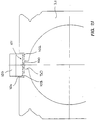
- FIG. 13 and 14 show an embodiment of a support 33, which are not frictionally engaged by the spindle thread 28, but is driven positively.
- the support 33 has a substantially annular support member 90 which has a spindle recess 91 in which the spindle 41 is slidably received.
- the support 33 has also a slide-like engagement part 92 which in a radially extending recess 93 in the support part 90 is guided radially displaceable.
- the engagement part 92 has a concave engaging portion complementary to the spindle 41 93, which engages with the spindle thread 28 is feasible.
- the engagement section 93 a complementary to the spindle thread 28 Threaded through which the engaging member 92 when it is pushed against the spindle 41, with this in engagement is.
- the engagement part 92 stands in the engaged state on the inner wall of the housing section 21 on.
- the solvents for releasing the engagement between the Support 33 and the spindle 41 point as in FIG. 13 is shown, a release sink 96 into which the engaging member 92 is displaceable, so that the engagement section 93 with the spindle thread 28 disengages.
- This can be done by Gravity, but preferably by a spring device can be reached, the engagement part 92 against the inner wall of the housing section 21 presses, but in the figures is not explicitly shown.
- This version of the support is characterized by its particularly simple structure and ensures secure engagement between the support and the spindle, which prevents the spindle 41 from slipping.
- the supports 33 in the corresponding Position held and the spindle 41 can be rotated to drive the spindle nut 42.
- the spindle nut 42 also migrates beyond the next support 33, this will be Support also shifted and comes with the spindle 41 engaged.
- the spindle 41 is rotated in opposite directions and the Spindle nut 42 moved backwards accordingly the supports that clamp the spindle thread 28 or with are engaged, also by the spindle 41 driven backwards and follow the spindle nut.
- To run the supports 33 over the first rest area so the first support from the appropriate solvent Spindle thread disengaged and stopped.
- the subsequent support pushes the stopped support however continue and will itself at the appropriate rest stop stopped.
- the further pushed support is on stopped accordingly at the next rest stop.
- the displaceability of the supports according to the different versions is thus effected in that the Supports can be brought into engagement with the spindle and are driven by the spindle itself and that at Resting points at which the supports are stopped should, release mechanisms are provided, the engagement loosen between the support and the spindle, the Support engages with the release mechanism by the support is pushed onto this.
- the release mechanism is so by shifting the support itself activated.
- the spindle housing portion has 21 a longitudinal slot 30 through which the connecting element 29 extends.
- one elastic fastener tape 100 is provided which the longitudinal slot 30 closes on both sides of the connecting element 29.
- Receiving recess 101 formed in the fastener tape 100 is included.
- the Receiving recess 101 basically a bottom 102 in the the longitudinal slot 30 opens, and two opposite Side walls 103, so that the receiving recess 101 a in has an essentially groove-like shape.
- a width V of the receiving recess 101 i.e. the distance between the two side walls 103 from one another, smaller than the width of the fastener tape 100 in the relaxed state. Therefore, as shown in Fig. 22, the bulge elastic fastener tape 100 and expresses itself due to its Internal stress against the side walls 103 so that the longitudinal slot 30 sealed against the exterior of the housing is.
- the width V of the receiving recess but also equal to or greater than the width of the elastic fastening tape 100 in the relaxed state, wherein in an opening area of the groove-shaped recess 101 to the outside of the housing on the two side walls 103 in each case a rib-like projection 104 is formed, whose distance from each other is smaller than the width of the Closure tape to prevent the inadvertent slipping out of the To prevent closure tape.
- the width of the recess 101 23 can, however, also be smaller than the width of the fastener tape 100, whereby the seal is further improved.
- the distance U the Projections from the bottom 102 are preferably larger than that Thickness T of the fastener tape 100 to thread it in and out of the fastener tape 100 into the receiving recess 101 improve, as will be explained later.
- the receiving recess 101 can also have a dovetail cross-section, as in FIG. 24 is shown.
- the opening area of the swallow-shaped Recess 101 is also in this embodiment is narrower than the elastic fastening tape 100 wide, so that accidental slipping out and an effective seal is guaranteed.
- the tape guide means 105 two rotatable guide rollers 106 and 107, one of which is the guide band 100 outside the Receiving recess 101 leads on the outside of the housing, while the other guide roller 107, the one with the opposite one Side of the fastener tape 100 (based on the first guide roller 106) is in contact, the fastener tape 100, as can be seen in FIGS. 15 and 21, into the receiving recess 101 pushes in.
- the buckle mechanism 108 has a camber wedge 109 which is transverse to the longitudinal direction of the Closure tape 100 has convexly curved pressure surface 110, which can be seen in Fig. 15 to the longitudinal direction the receiving recess 101 is inclined to against the Longitudinal slot 30 facing side of the fastener tape 100 in to press a central region of the fastener tape.
- On the opposite side of the fastener tape is a counterpart 111 arranged, the two parallel projecting Has push tabs 112 on the opposite side of the fastening tape 100 press in the edge area, so that the fastener tape 100 due to the pressure of the Arch wedge 109 and the counterpart 111 bulges, as in Fig. 17 can be seen.
- the pressure lugs 112 are corresponding the pressure surface 110 of the wedge 109 inclined to the longitudinal direction the receiving recess and parallel to the longitudinal direction the curved printing surface 110.
- the pressure wedge 109 can with the connecting element 29 can be connected and can additionally by Support wedge support 113 on spindle 41.
- the wedge and the tape guide device could be by means of the support 113 is also driven by the spindle itself become.
- the Arch wedge 109 in a region of the fastening tape 100 from below against this, between the two guide rollers 107 and 106 lies and in particular from both guide rollers is spaced. This takes into account the fact that an elastic band is usually only uniaxial can be bent.
- the fastener tape 100 on the guide roller 107 first after deflected above (in the sense of FIG. 16), and after the deflection by the arch mechanism 108 parallel about an axis bent or arched to the longitudinal direction of the fastener tape, to reduce the effective width of the fastener tape and threading the thread in and out of the To facilitate recess 101.
- FIG 18 and 19 Another embodiment of arch mechanism 108 is shown in FIG 18 and 19, wherein instead of the arch wedge Arch pin 209 is used against the longitudinal slot 30 facing side of the fastener tape 100 in the central region presses.
- a counter roller 211 On the opposite side of the fastener tape a counter roller 211 is arranged which is rotatable is stored and 2 rounded projections in the edge areas 212, which is on the opposite side of the Press the fastening tape 100.
- the Press mandrel 209 is essentially formed by a pin which is cranked around the fastener tape 100 gently into the arched Press shape.
- the tape guide device synchronized with the spindle nut to the left or moved right, causing the fastener tape in the direction of movement seen in front of the connecting element 29 from the Receiving recess 101 led out (under curvature or Twist of the fastener tape) and behind the connecting element 29 back into the receiving recess (again under Curvature or twisting of the band).
- the tape guide and the arching mechanism in synchronism with the connecting element 29 or the spindle nut 42 carried so that the fastener tape 100 is zipped in and threaded out.
- the tape guide and the buckling mechanism are, though 1 only on one side of the connecting element 29 shown on both sides of the connecting element 29 intended.
Description
Die vorliegende Erfindung betrifft eine Lineargetriebeeinheit mit einem Rahmen und einer drehbar an dem Rahmen gelagerten Spindel mit einer zugehörigen Spindelmutter.The present invention relates to a linear gear unit with a frame and one rotatably mounted on the frame Spindle with an associated spindle nut.
Derartige Lineargetriebeeinheiten dienen der Umwandlung einer rotatorischen Bewegung in eine translatorische Bewegung und werden häufig für den Antrieb von Maschinenelementen verwendet, die mittels eines Kraftübertragungselementes mit der Spindelmutter verbunden werden, wobei die Spindel zumeist von einem Elektromotor, ggf. auch von Hand angetrieben wird. In der Praxis sind Lineargetriebeeinheiten bekannt, deren Spindel mit der dazugehörigen Spindelmutter in einem rohrförmigen Gehäuse aufgenommen und an diesem drehbar gelagert ist. Das Gehäuse weist einen Längsschlitz auf, durch den sich das mit der Spindelmutter verbundene Kraftübertragungselement erstreckt. Um das Eindringen von Staub und Schmutz in das Gehäuse zu verhindern, ist der Längsschlitz beidseitig des Kraftübertragungselementes häufig mit mehr oder weniger komplizierten Verschlußbandeinrichtungen verschlossen. Such linear gear units are used for conversion a rotational movement into a translatory movement and are often used to drive machine elements used with a power transmission element the spindle nut are connected, the spindle mostly is driven by an electric motor, possibly also by hand. In practice, linear gear units are known, the Spindle with the associated spindle nut in a tubular Housing added and rotatably mounted on this. The housing has a longitudinal slot through which the power transmission element connected to the spindle nut extends. To prevent dust and dirt from entering To prevent the housing is the longitudinal slot on both sides of the Power transmission element often with more or less complicated fastener tape devices closed.
Eine Lagerung der Spindel nur an deren Endbereichen erweist sich als problematisch insbesondere bei der Verwendung von längeren, dünneren Spindeln und deren Antrieb mit höheren Drehzahlen, da sich die Spindel in diesem Falle durchbiegen kann und leicht in Schwingungen versetzt wird, wodurch die Spindel und die dazugehörige Spindelmutter sowie das Gehäuse übermäßig beansprucht und beschädigt werden können. Um dies zu verhindern, muß die Spindel in den Bereichen zwischen der Spindelmutter und den endseitigen Lagern der Spindel zusätzlich radial abgestützt werden. Da sich die Länge dieser Bereiche der Spindel mit der Stellung der Spindelmutter ändert, muß auch die Abstützung der Spindel entsprechend der Stellung der Spindelmutter wandern, um eine Behinderung der Längsbewegung zu vermeiden.Storage of the spindle only proves at its end areas turned out to be problematic especially when using longer, thinner spindles and their drive with higher ones Speeds, because in this case the spindle will bend can and is easily vibrated, whereby the Spindle and the associated spindle nut as well as the housing can be overused and damaged. To do this To prevent the spindle in the areas between the Spindle nut and the end bearings of the spindle additionally be supported radially. Because the length of this Areas of the spindle with the position of the spindle nut changes, the support of the spindle must also correspond to the Position the spindle nut to hinder a disability Avoid longitudinal movement.
Aus der EP-A-0327705 ist bereits eine Lineargetriebeeinheit der eingangs genannten Art bekannt geworden, deren Spindel durch mehrere auf beiden Seiten der Spindelmutter angeordnete Abstützungen radial abgestützt wird, die mit der Spindelmutter in Längsrichtung relativ zu dem Gehäuse und der Spindel verstellt werden. Während die in Bewegungsrichtung gesehen vor der Spindelmutter liegenden Abstützungen durch diese direkt angeschoben werden können, ist für die hinter der Spindelmutter liegenden Abstützungen eine recht aufwendige und komplizierte Mitnehmereinrichtung vorgesehen, um die hinter der Spindelmutter liegenden Abstützungen mit dieser mitzuschleppen. Diese Mitnehmereinrichtung ist aufwendig zu fertigen, erhöht die Anzahl der Bauteile der Lineargetriebeeinheit und zeigt darüber hinaus keine kompakte Bauform des Lineargetriebes.A linear gear unit is already known from EP-A-0327705 of the type mentioned, whose spindle by several arranged on both sides of the spindle nut Outriggers are supported radially with the spindle nut in the longitudinal direction relative to the housing and the Spindle can be adjusted. While in the direction of movement seen supports in front of the spindle nut this can be pushed directly is for the rear the spindle nut lying supports a very expensive and complicated driver device provided to the supports lying behind the spindle nut with this to drag along. This driver device is expensive manufacture increases the number of components of the linear gear unit and also shows no compact Design of the linear gear.
Der Erfindung liegt daher die Aufgabe zugrunde, eine die Nachteile des Standes der Technik vermeidende verbesserte Lineargetriebeeinheit der eingangs genannten Art zu schaffen. The invention is therefore based on the object Improved to avoid disadvantages of the prior art To create linear gear unit of the type mentioned.
Insbesondere soll eine einfache Verstellung der Abstützung möglich sein, um die Spindel entsprechend der Stellung der Spindelmutter an verschiedenen Stellen abzustützen.In particular, a simple adjustment of the support is intended be possible to position the spindle according to the Support the spindle nut in different places.
Erfindungsgemäß wird diese Aufgabe durch die Merkmale des Anspruchs 1 gelöst. Die abhängigen Ansprüche enthalten weitere Ausgestaltungen.According to the invention, this object is achieved by the features of claim 1. The dependent claims contain further refinements.
Die Abstützung wird also unmittelbar durch die Spindel selbst angetrieben. Insbesondere kann die Abstützung mutterartig durch das Spindelgewinde angetrieben sein und, wenn die Abstützung eine gewünschte Stellung erreicht hat, von der antreibenden Spindel entkoppelt werden, so daß sich die Spindel drehen kann, ohne die Abstützung zu bewegen. Durch den aktiven Antrieb der Abstützung durch die Spindel selbst erübrigt sich eine mit der Spindelmutter verbundene Mitnehmereinrichtung, so daß die Lineargetriebeeinheit einfach und kompakt zu bauen ist.The support is thus directly by the spindle itself driven. In particular, the support can be nut-like be driven by the spindle thread and if the Support has reached a desired position from which driving spindle are decoupled so that the Spindle can rotate without moving the support. By the active drive of the support by the spindle itself there is no need for a driver device connected to the spindle nut, so that the linear gear unit simple and is compact to build.
Um die Abstützung direkt durch die Spindel zu bewegen, kann vorzugsweise die Spindel mit einer Außenseite des Spindelgewindes von der Abstützung geklemmt werden, so daß die Abstützung in Reibschluß mit den Außenseiten der Gewindeflanken gebracht wird und als mit dem Spindelgewinde eingreifende Mutter wirkt. Zweckmäßigerweise besitzt die Abstützung eine Spindelausnehmung, in der die Spindel aufgenommen und klemmbar ist. Um die Abstützung an einer gewünschten Stelle zu halten, sind Lösemittel vorgesehen, die die Klemmung zwischen der Abstützung und dem Spindelgewinde lösen, so daß ein Drehen der Spindel keinen Vorschub der Abstützung bewirkt. Die Klemmung wird hierbei zumindest soweit gelöst, daß die Spindel in der Spindelausnehmung durchdreht und das Spindelgewinde in der Spindelausnehmung der Abstützung nicht greift.To move the support directly through the spindle, you can preferably the spindle with an outside of the spindle thread be clamped by the support so that the support in frictional engagement with the outside of the thread flanks is brought and as engaging with the spindle thread Mother works. The support expediently has a Spindle recess in which the spindle is received and clamped is. To support at a desired location hold, solvents are provided that the clamping between loosen the support and the spindle thread so that a Turning the spindle does not advance the support. The clamping is at least solved so far that the Spindles in the spindle recess and the spindle thread does not engage in the spindle recess of the support.
Ein aktives Antreiben der Abstützung durch die Spindel selbst kann jedoch nicht nur durch Reibschluß und Klemmung der Außenseite des Spindelgewindes erreicht werden, vielmehr ist es auch möglich, die Abstützung formschlüssig, beispielsweise mittels eines an der Abstützung gelagerten Eingriffschiebers, der eine oder mehrere zu dem Spindelgewinde komplementäre Gewindeflanken aufweist und mit dem Spindelgewinde in Eingriff bringbar ist, an die Spindel anzukoppeln. In diesem Falle können die Lösemittel eine Bewegungseinrichtung aufweisen, die den Eingriffsschieber bewegt und von dem Spindelgewinde außer Eingriff bringt. Gemäß einer vorteilhaften Ausgestaltung der Erfindung besitzt die Abstützung zwei Abstützteile die miteinander verbunden und relativ zueinander beweglich sind, wobei die beiden Abstützteile oder zumindest eines hiervon in einer ersten Stellung der beiden Abstützteile zueinander mit der Spindel in Eingriff sind, und insbesondere das Spindelgewinde klemmen, und in einer zweiten Stellung vom Antrieb durch die Spindel abgekoppelt sind.An active driving of the support by the spindle itself can not only by friction and clamping the Outside of the spindle thread can be reached, rather it is also possible to form-fit the support, for example by means of an engagement slide mounted on the support, the one or more to the spindle thread has complementary thread flanks and with the spindle thread can be engaged to couple to the spindle. In this case, the solvents can be a moving device have, which moves the engagement slide and from which Disengages spindle thread. According to an advantageous Embodiment of the invention has two supports Support parts that are connected to each other and relative to each other are movable, the two support parts or at least one of them in a first position of the two support parts are mutually engaged with the spindle, and in particular clamp the spindle thread, and in a second Position are decoupled from the drive by the spindle.
Hierbei ist die Bezeichnung Abstützteil nicht so zu verstehen, daß beide Teile per se die Funktion des Abstützens erfüllen müssen, vielmehr kann eines der beiden auch lediglich dem Eingriff dienen und ist als Teil der Abstützung zu verstehen.The term support part is not to be understood here that both parts per se have the function of supporting must meet, rather one of the two can only serve the intervention and is part of the support too understand.
Vorzugsweise ist eine Federeinrichtung zur Vorspannung der beiden Abstützteile in eine der beiden Endstellungen, vorzugsweise in deren Eingriffsstellung, vorgesehen.Preferably, a spring device for prestressing the two support parts in one of the two end positions, preferably in their engaged position.
Um die Abstützung von dem Antrieb durch die Spindel zu lösen, sind die beiden Abstützteile relativ zueinander zu bewegen und in die entsprechende Stellung zueinander zu bringen, so daß der Eingriff zwischen Spindel und Abstützung gelöst ist. Die Lösemittel sind hierzu als Bewegungseinrichtung ausgebildet und wirken vorzugsweise mit der Federeinrichtung zusammen bzw. auf diese ein. Vorzugsweise besitzen die Lösemittel ein Eingriffsteil, daß in Abhängigkeit von der Längsstellung der Abstützung mit der Federeinrichtung in Eingriff gebracht wird. Dies kann in konstruktiv einfacher Weise dadurch erreicht werden, daß das Eingriffsteil fest, vorzugsweise mit einer Innenwand eines Gehäuseabschnittes verbunden, angeordnet ist und mit der Abstützung bzw. der Federeinrichtung in Eingriff gelangt, wenn die Abstützung die Position des Eingriffteils erreicht bzw. über diese Stellung verschoben wird.To release the support from the drive through the spindle, the two support parts must be moved relative to each other and to bring them into the corresponding position, so that the engagement between the spindle and the support is released. For this purpose, the solvents are designed as movement devices and preferably cooperate with the spring device or on this one. The solvents preferably have one Engagement part that depending on the longitudinal position of the Support brought into engagement with the spring device becomes. This can be achieved in a structurally simple manner be that the engaging part firmly, preferably with connected to an inner wall of a housing section, arranged and with the support or the spring device in Engagement occurs when the support is in the position of the Intervention part reached or moved over this position becomes.
Die Eingriffs lösung zwischen der Abstützung und der Spindel erfolgt hierbei dadurch, daß die Abstützung im Eingriffszustand mit der Spindel in den Wirkungsbereich der ortsfest angeordneten Lösemittel verschoben wird, in dem die Lösemittel eine Bewegung der beiden Abstützteile zueinander bewirken, so daß der Eingriff mit der Spindel gelöst wird und die Abstützung angehalten wird. Um die Abstützung aus dem Wirkungsbereich der Lösemittel hinaus zu bewegen, kann die Abstützung beispielsweise durch die Spindelmutter oder eine nachfolgende Abstützung angeschoben werden.The engagement solution between the support and the spindle takes place here in that the support in the engaged state with the spindle in the effective range of the stationary arranged solvent is moved in which the solvent a movement of the two support parts to each other cause so that the engagement with the spindle is released and the support is stopped. To get the support from the Moving the range of action of the solvents can Support, for example, by the spindle nut or a subsequent support can be pushed.
Um eine wirkungsvolle Klemmung des Spindelgewindes durch die Abstützung zu erzielen und gleichzeitig eine stabile in jeder beliebigen radialen Richtung wirksame Abstützung der Spindel zu erreichen, sollte die Abstützung die Spindel formgenau umgeben. Es ist daher zweckmäßig, daß die beiden Abstützteile jeweils eine Spindelausnehmung besitzen, in der die Spindel aufgenommen ist und in Spindel längsrichtung hintereinander auf der Spindel angeordnet sind, wobei die beiden Abstützteile, um die Spindel zu klemmen, derart beweglich sind, daß die Längsachsen der Spindelausnehmungen zueinander bzw. relativ zu der Längsachse der Spindel in eine nicht koaxiale Stellung gebracht werden können. Um, z.B. bei sehr steilem Bewegungsgewinde, ein Durchrutschen des Spindelgewindes in der Spindelausnehmung der Abstützung, d. h. ein Durchdrehen der Spindel, zu vermeiden, ist es vorteilhaft, wenn die Abstützung an einer dem Spindelgewinde zugewandten Seite, d. h. an einer Innenoberfläche der Spindelausnehmung, den Eingriff unterstützende Mittel, vorzugsweise eine schraubenförmige, insbesondere zu dem Spindelgewinde komplementäre Rippe, aufweist, die das Greifen der Abstützung auf der Spindel verbessern.For effective clamping of the spindle thread by the To achieve support while maintaining a stable in everyone effective support of the spindle in any radial direction To achieve this, the support should fit the spindle precisely surround. It is therefore appropriate that the two support parts each have a spindle recess in which the spindle is recorded and in the longitudinal direction one behind the other are arranged on the spindle, the two support parts, to clamp the spindle, are so movable that the Longitudinal axes of the spindle recesses to one another or relative to the longitudinal axis of the spindle in a non-coaxial position can be brought. Um, e.g. with very steep movement thread, a slipping of the spindle thread in the spindle recess the support, d. H. a spinning of the To avoid spindle, it is advantageous if the support on a side facing the spindle thread, d. H. on an inner surface of the spindle recess, the engagement supporting means, preferably a helical, rib complementary to the spindle thread in particular, which has the gripping of the support on the spindle improve.
Eine besonders wirkungsvolle Klemmung kann in einfacher Weise dadurch erreicht werden, daß zumindest eines der beiden Abstützteile auf der Spindel verkantet werden kann. Hierzu können die beiden Abstützteile relativ zueinander um eine zur Längsrichtung der Spindel im Wesentlichen senkrechte Achse kippbar sein, wobei vorzugsweise zwischen den beiden Abstützteilen zwei gegenüberliegende Federelemente vorgesehen sind, die die beiden Abstützteile miteinander verbinden und in eine Stellung relativ zueinander vorspannen. Dies besitzt den Vorteil, daß durch die Doppelfunktion der Federelemente, nämlich Verbindung und Vorspannung, der Aufbau der Abstützung sehr einfach, kompakt und leicht ist. Darüber hinaus sind bei entsprechender Geometriefestlegung durch das Verkanten der Abstützteile auch mit relativ kleinen und leichten Federn hohe Klemmkräfte erzielbar, die einen zuverlässigen Antrieb der Abstützung sicherstellen.A particularly effective clamping can be done in a simple manner can be achieved in that at least one of the two Support parts on the spindle can be tilted. For this can the two support parts relative to each other by one Longitudinal direction of the spindle essentially vertical axis be tiltable, preferably between the two support parts two opposite spring elements are provided, that connect the two support parts together and into one Preload position relative to each other. This owns the Advantage that the double function of the spring elements namely connection and preload, the structure of the support is very simple, compact and light. In addition, at appropriate geometry definition by tilting the Support parts also with relatively small and light springs high clamping forces can be achieved, which is a reliable drive the support.
Vorzugsweise besitzt zumindest eines der Federelemente einen bogenförmigen Abschnitt, dessen Krümmung die Länge des Federelementes und hierdurch die Stellung der beiden Abstützteile zueinander bestimmt. Gemäß einer bevorzugten Weiterbildung der Erfindung wirken die Lösemittel auf den bogenförmig gekrümmten Abschnitt des Federelementes ein, um die Stellung der beiden Abstützteile zueinander zu verändern. Vorzugsweise ist der gekrümmte Abschnitt des Federelementes derart angeordnet, daß sich dessen Sehne parallel zur Verschieberichtung der Abstützung, d.h. parallel zur Spindellängsrichtung erstreckt, wobei das Eingriffsteil der Lösemittel ein starrer Nocken sein kann, der mit dem bogenförmigen Abschnitt des Federelementes in Eingriff bringbar ist. Hierdurch kann die Klemmung der Abstützung sehr einfach und effektiv dadurch gelöst werden, daß die Abstützung mit dem bogenförmigen Abschnitt des Federelementes auf den Nocken fährt, wodurch die Krümmung des bogenförmigen Abschnitts und hierdurch die Stellung der beiden Abstützteile zueinander verändert wird. Diese Ausführung ist insbesondere hinsichtlich ihres sehr einfachen und zuverlässigen Aufbaus von Vorteil.At least one of the spring elements preferably has one arcuate section, the curvature of which is the length of the Spring element and thereby the position of the two support parts determined to each other. According to a preferred development the invention act on the arc-shaped solvents curved portion of the spring element to the position to change the two support parts to each other. Preferably the curved section of the spring element is arranged in such a way that its chord is parallel to the direction of displacement the support, i.e. parallel to the longitudinal direction of the spindle extends, the engaging part of the solvent being a rigid one Can be the cam with the arcuate portion of the Spring element can be brought into engagement. This allows the This makes clamping the support very easy and effective be solved that the support with the arcuate Section of the spring element moves on the cam, whereby the curvature of the arcuate portion and thereby the Position of the two support parts to each other is changed. This version is particularly in terms of its very simple and reliable construction is an advantage.
Eine vorteilhafte Ausführungsform besteht darin, daß der gekrümmte Abschnitt des Federelementes einer Innenwand des Gehäuseabschnitts zugewandt ist und das Eingriffsteil einen sich in Spindellängsrichtung erstrecken den, insbesondere keilförmigen Nockenabschnitt aufweist, wobei der Nockenabschnitt von der Innenwand des die Abstützung umgebenden Gehäuses vorspringen, oder auch eine Absenkung in dieser Innenwand bilden kann, wodurch der gekrümmte Abschnitt in eine weniger stark gekrümmte Form gedrückt wird oder in eine stärker gekrümmte Form ausballen kann.An advantageous embodiment is that the curved section of the spring element of an inner wall of the Housing section faces and the engaging part extend in the longitudinal direction of the spindle, in particular has a wedge-shaped cam section, the cam section from the inner wall of the one surrounding the support Projecting housing, or a lowering in this Can form inner wall, whereby the curved portion in a less curved shape is pressed or into a can form a more curved shape.
Ebenso vorteilhaft kann der gekrümmte Abschnitt des Federelementes in einer Nut in einer Umfangsseite des Abstützelementes angeordnet sein und das Eingriffsteil einen sich in Spindellängsrichtung erstreckenden Schienabschnitt aufweisen, der in die Nut eingreift und Ausnehmungen aufweist, wobei der gekrümmte Abschnitt durch den Schienabschnitt in eine weniger stark gekrümmte Form gedrückt wird und in den Ausnehmungen in eine stärker gekrümmte Form springen kann.The curved section of the spring element can also be advantageous in a groove in a peripheral side of the support element be arranged and the engaging part in one Have a spindle section extending in the longitudinal direction of the spindle, which engages in the groove and has recesses, wherein the curved section through the rail section in a less curved shape is pressed and into the Recesses can jump into a more curved shape.
Den genannten Ausführungsformen der Lösemittel und der Federeinrichtung liegt gemeinsam das Prinzip zugrunde, daß ortsfeste Eingriffsteile der Lösemittel durch Verschieben der Abstützung mit gekrümmten Abschnitten der Federelemente in Eingriff gebracht werden können und die Krümmung dieser bogenförmigen Abschnitte verändern, um die Klemmung der Spindel durch die Abstützung zu lösen.The mentioned embodiments of the solvent and The spring device is based on the principle that stationary engagement parts of the solvents by moving the Support with curved sections of the spring elements in Can be engaged and the curvature of this arcuate sections change to the clamping of the Loosen the spindle through the support.
Um auch mit geringen Spannkräften mittels günstiger Hebelverhältnisse relativ hohe Klemmkräfte auszuüben und die Abstützung wirkungsvoll mit dem Spindelgewinde zu verklemmen, kann zwischen den beiden Abstützteilen auch ein Exzentermechanismus vorgesehen sein, wodurch zumindest eines der Abstützteile durch Verdrehen desselben mit dem Spindelgewinde verklemmt. Vorzugsweise ist wenigsten eines der Abstützteile relativ zu dem anderen um eine zur Längsachse der Spindel parallele und exzentrische Achse verdrehbar, wobei eine Federeinrichtung zur Verdrehung und Vorspannung der beiden Abstützteile zueinander vorgesehen ist. Die exzentrische Verklemmung zeichnet sich unter anderem dadurch aus, daß zur Verdrehung des exzentrisch gelagerten Abstützteiles kleine Kräfte ausreichen, die durch die Verlagerung der Spindelausnehmung relativ zur Spindel aufgrund der exzentrischen Lagerung in relativ hohe Klemmkräfte umgesetzt werden, so daß die Abstützung mit dem Spindelgewinde wirkungsvoll verklemmt ist. Anstelle des Exzentermechanismusses zwischen den beiden Abstützteilen ist es ebenfalls möglich, die Abstützung, die in diesem Falle einteilig ausgeführt sein kann, als Ganzes im Gehäuse bezogen auf die Spindel exzentrisch zu lagern, so daß ein Verdrehen der Abstützung die Spindelausnehmung in der Abstützung relativ zur Spindel versetzt. Die zuvor beschriebene Ausführung des Exzentermechanismusses zwischen den beiden Abstützteilen besitzt jedoch Vorteile hinsichtlich eines einfachen Aufbaus des Gehäuses.To even with low clamping forces by means of favorable leverage ratios to exert relatively high clamping forces and support can effectively jam with the spindle thread there is also an eccentric mechanism between the two support parts be provided, whereby at least one of the support parts jammed with the spindle thread by turning it. At least one of the support parts is preferably relative to the other about a parallel to the longitudinal axis of the spindle and eccentric axis rotatable, with a spring device for twisting and preloading the two support parts to each other is provided. The eccentric deadlock is characterized, inter alia, in that for twisting of the eccentrically mounted support part small forces sufficient by the displacement of the spindle recess relative to the spindle due to the eccentric bearing in relatively high clamping forces are implemented, so that the support is effectively jammed with the spindle thread. Instead of the eccentric mechanism between the two Support parts, it is also possible to support the in this case can be made in one piece, as a whole in To store the housing eccentrically in relation to the spindle, so that twisting the support in the spindle recess Support offset relative to the spindle. The one described earlier Execution of the eccentric mechanism between the However, both support parts have advantages in terms of a simple construction of the housing.
Um die Klemmung der exzentrischen Abstützteile und das Lösen der selben in Abhängigkeit der axialen Stellung der Abstützteile in konstruktiv sehr einfacher Weise zu steuern, ist vorzugsweise eine Drehführungseinrichtung zur Drehführung bzw. zur Festlegung der rotatorischen Stellung der Abstützteile vorgesehen. Vorzugsweise ist für jedes der Abstützteile eine separate Drehführung vorgesehen, die beispielsweise als Längsnut und Eingriffsteil zwischen dem Gehäuse und dem entsprechenden Abstützteil ausgebildet sein kann, wobei die Längsnut und/oder das Eingriffsteil eine Steuerkurve festlegen und die rotatorische Stellung der beiden Abstützteile zueinander in Abhängigkeit der axialen Stellung derselben steuern. Besonders einfach zu fertigen ist die Drehführungseinrichtung dadurch, daß eines der beiden Abstützteile durch eine sich gerade erstreckende Längsnut-Nuteingriffsteil-Verbindung, wobei die Längsnut und das komplementäre Eingriffsteil wahlweise an dem entsprechenden Abstützteil und dem Gehäuse ausgebildet sein können, drehfest geführt ist, während dem anderen Abstützteil eine Verdrehsteuervorrichtung zugeordnet ist, die vorzugsweise ein von einer Innenwand des Gehäuses vorspringendes keilförmig profiliertes Nockenteil und eine in einer Umfangsseite des Abstützteiles vorgesehene Längsnut umfaßt. In umgekehrter Weise kann jedoch auch das Abstützteil einen Eingriffsvorsprung, insbesondere einen von der Umfangsseite vorspringenden Stift haben, der mit dem Nockenteil in Eingriff bringbar ist oder alternativ mit einer in dem Gehäuse ausgebildeten Längssteuernut in Eingriff ist.To clamp and loosen the eccentric support parts the same depending on the axial position of the support parts to control in a structurally very simple manner preferably a rotation guide device for rotation guidance or to determine the rotational position of the support parts intended. Preferably for each of the support members a separate rotary guide is provided, for example as Longitudinal groove and engagement part between the housing and the corresponding support part can be formed, the Define longitudinal groove and / or the engaging part a control curve and the rotational position of the two support parts to each other depending on the axial position of the same Taxes. The rotary guide device is particularly easy to manufacture in that one of the two support parts through a straight longitudinal groove-groove engagement part connection, the longitudinal groove and the complementary engagement part optionally on the corresponding support part and the housing can be formed, is rotatably guided, a twist control device during the other supporting part is assigned, which is preferably one of an inner wall of the Protruding wedge-shaped cam part and one provided in a peripheral side of the support member Includes longitudinal groove. In reverse, however, that can also be the case Support part an engagement projection, in particular one of the circumferential side projecting pin that with the Cam part can be brought into engagement or alternatively with one longitudinal control groove formed in the housing is engaged.
Die zuvor beschriebenen Ausführungsformen mit Exzentermechanismus beruhen darauf, daß die Abstützung oder Teile hiervon zur Klemmung des Spindelgewindes verdrehbar sind und ein Drehmechanismus zur Drehung der Abstützung bzw. der entsprechenden Teile hiervon in eine klemmfreie Stellung entsprechend der axialen Stellung der Abstützung vorgesehen ist.The previously described embodiments with an eccentric mechanism are based on the fact that the support or parts thereof are rotatable for clamping the spindle thread and a Rotating mechanism for rotating the support or the corresponding Parts of it accordingly in a jam-free position the axial position of the support is provided.
Ein besonders einfacher Aufbau der Abstützung ist gemäß einer vorteilhaften Weiterbildung der Erfindung auch dadurch gegeben, daß die Abstützung zwei halbschalenförmige Abstützabschnitte besitzt, die zumindest auf einer Seite der Spindel voneinander getrennt sind und zwischen denen das Spindelgewinde eingespannt ist und die Lösemittel als Aufspreizeinrichtung zum Aufspreizen der Abstützabschnitte ausgebildet sind, wobei die Aufspreizeinrichtung vorzugsweise eine Längsnut zwischen den beiden Abstützabschnitten und ein Aufspreizteil, insbesondere einen mit der Längsnut in Eingriff bringbaren Spreiznocken aufweist. Diese halbschalenförmige Ausbildung der Abstützung zeichnet sich durch ihren sehr einfachen Aufbau und günstige Herstellbarkeit aus, wobei sich insbesondere auch für die Lösemittel konstruktiv sehr einfache Verhältnisse ergeben. Vorzugsweise ist die Abstützung einteilig als an einer Seite geschlitzter Ring ausgebildet, der aufgrund seiner Elastizität mit dem Spindelgewinde in Eingriff ist. Vorzugsweise besitzt die Abstützung an einer Innenseite ein zu dem Spindelgewinde komplementär ausgebildetes Gewinde, um den Eingriff zwischen der Abstützung und dem Spindelgewinde zu verbessern. Durch Aufspreizen der Abstützung werden die beiden Gewinde außer Eingriff gebracht.A particularly simple structure of the support is according to one advantageous further development of the invention given that the support two half-shell-shaped support sections owns at least on one side of the spindle are separated from each other and between which the spindle thread is clamped and the solvent as a spreading device designed to spread the support sections are, the spreading device preferably a Longitudinal groove between the two support sections and a Spreading part, in particular one with the longitudinal groove in engagement brings expandable cams. This half-shell shape Training of the support is characterized by its very simple structure and cheap manufacturability, whereby in particular for the solvents, very simple in terms of construction Relationships. The support is preferred formed in one piece as a ring slotted on one side, which due to its elasticity with the spindle thread in Intervention is. The support preferably has one Inside a complementary to the spindle thread Thread to engage between the support and the Improve spindle thread. By spreading the support the two threads are disengaged.
Um die Spindelabstützung insbesondere für lange und relativ dünne Spindeln zu verbessern, sind vorzugsweise auf beiden Seiten der Spindel mehrere Abstützungen vorgesehen.To the spindle support especially for long and relative To improve thin spindles are preferable on both Several supports are provided on the side of the spindle.
Ein weiterer Aspekt der Erfindung liegt darin, daß das die Spindel aufnehmende Gehäuse einen Längsschlitz aufweist, durch den sich ein mit der Spindelmutter verbundenes Verbindungselement erstreckt und ein elastisches Verschlußband zum Verschließen des Längsschlitzes vorgesehen ist, wobei das Gehäuse eine Aufnahmeausnehmung zur Aufnahme des Verschlußbandes aufweist, deren Öffnungsbereich zur Gehäuseaußenseite eine geringere Breite als das Verschlußband hat und Mittel zur Verringerung der wirksamen Bandbreite vorgesehen sind.Another aspect of the invention is that the Spindle receiving housing has a longitudinal slot, through which there is a connecting element connected to the spindle nut extends and an elastic fastener tape for Closing the longitudinal slot is provided, the Housing a receiving recess for receiving the fastener tape has, the opening area to the outside of the housing has a smaller width than the fastener tape and medium are provided to reduce the effective bandwidth.
Um das Eindringen von Schmutz und Staub in das Innere des Spindelgehäuses zu verhindern, wodurch die Lagerung der Spindel und insbesondere die verstellbaren Abstützungen beeinträchtigt werden könnten, muß der Längsschlitz in dem Gehäuse für das Verbindungselement, mit dem ein jeweiliges Maschinenelement mit der Spindelmutter verbunden ist, verschlossen werden. In der Praxis war es bislang üblich, den Ldngsschlitz durch ein elastisches Verschlußband zu verschließen, das mittels seitlich angeformter Halteflansche in längsverlaufenden, rillenartigen Vertiefungen der beiden den Längsschlitz begrenzenden Gehäusewände lösbar verrastet wurde. Eine derartige Ausbildung des Verschlußbandes verteuerte jedoch zum einen die Herstellung des entsprechenden Bandes, zum anderen war die Haltbarkeit der angeformten Halteflansche unbefriedigend und darüber hinaus mußten die rillenartigen Vertiefungen in den Seitenwänden des Längsschlitzes sehr genau bearbeitet werden, um ein dichtes Verschließen zu erreichen.To prevent dirt and dust from entering the inside of the To prevent spindle housing, thereby the storage of the Spindle and especially the adjustable supports could be affected, the longitudinal slot in the Housing for the connecting element with which a respective Machine element is connected to the spindle nut, closed become. In practice, it has so far been the norm To close the longitudinal slit with an elastic fastening tape, that by means of laterally molded holding flanges in longitudinal, groove-like depressions of the two den Longitudinal slot bounding housing walls releasably locked has been. Such a formation of the fastener tape more expensive however, on the one hand, the production of the corresponding Tape, on the other hand was the durability of the molded Holding flanges unsatisfactory and beyond that they had to groove-like depressions in the side walls of the longitudinal slot can be edited very precisely to a dense Closing to achieve.
Um einen verbesserten Verschlußmechanismus zu schaffen, der die Nachteile herkömmlicher Lösungen vermeidet und in einfacher Weise ein Verschließen des Gehäuses ermöglicht, zeichnet sich die Lineargetriebeeinheit nach einem weiteren Merkmal der Erfindung dadurch aus, daß das Verschlußband in einer Aufnahmeausnehmung aufgenommen ist, die einen Dichtabschnitt besitzt, der schmäler ist als die Breite des Verschlußbandes, wobei zum Einfädeln des Verschlußbandes in die Aufnahmeausnehmung eine Einrichtung zur Verringerung der wirksamen Bandbreite vorgesehen ist. Hierdurch kann ein einfaches und billiges Verschlußband mit im wesentlichen rechteckigen Querschnitt verwendet werden.To create an improved locking mechanism that avoids the disadvantages of conventional solutions and in simpler Enables a closure of the housing, draws the linear gear unit after another Feature of the invention in that the fastener tape in a receiving recess is received, which has a sealing section that is narrower than the width of the Closure tape, whereby for threading the closure tape in the receiving recess is a device for reducing the effective bandwidth is provided. This can be a simple and cheap fastener tape with essentially rectangular cross section can be used.
Die Aufnahmeausnehmung ist vorzugsweise im wesentlichen nutförmig ausgebildet und weist zwei Seitenwände und einen Boden auf, in den der zu verschließende Längsschlitz mündet. Um ein unbeabsichtigtes Herausrutschen des Verschlußbandes aus der Nut zu verhindern und die Abdichtung zu verbessern, kann gemäß einer vorteilhaften Ausführungsform der Erfindung in einem Öffnungsbereich der Nut auf einer oder auf beiden Seiten der Nut die entsprechende Seitenwand jeweils einen vorzugsweise rippenartigen Vorsprung aufweisen, wobei die Seitenwände in dem Bereich zwischen den Vorsprüngen und dem Boden einen Abstand haben können, der größer ist als die Breite des Verschlußbandes. Der Öffnungsbereich der Nut kann jedoch auch ohne Vorsprünge ausgebildet sein, wobei die Seitenwände voneinander einen Abstand haben sollten, der kleiner ist als die Breite des Verschlußbandes derart, daß das Verschlußband zwischen den beiden Seitenwänden elastisch geklemmt ist. Hierdurch wird ebenfalls ein unbeabsichtigtes Herausrutschen des Verschlußbandes aus der Nut verhindert und die Abdichtung zwischen Verschlußband und Gehäuse verbessert.The receiving recess is preferably essentially groove-shaped and has two side walls and one Floor in which the longitudinal slot to be closed opens. To prevent the fastener tape from accidentally slipping out prevent from the groove and improve the seal, can according to an advantageous embodiment of the invention in an opening area of the groove on one or both Sides of the groove the corresponding side wall one each preferably have rib-like projection, the Sidewalls in the area between the protrusions and the Floor can have a distance that is greater than that Width of the fastener tape. The opening area of the groove can however, also be formed without projections, the Sidewalls should have a distance from each other that is smaller than the width of the fastener tape such that the fastener tape between the two side walls is elastic is clamped. This also becomes an unintended one Prevents the fastener tape from slipping out of the groove and improved the seal between the fastener tape and the housing.
Um das Verschlußband einfach und ohne zu verhaken in die Aufnahmeausnehmung einzuführen, besitzen die Mittel zur Verringerung der wirksamen Bandbreite vorzugsweise eine Bandführungseinrichtung mit einem Wölbemechanismus zur Führung des Verschlußbandes in einem gewölbten Zustand beim Ein- bzw. Ausfädeln des Verschlußbandes. Hierdurch wird das Verschlußband in einem Querschnitt quer zur Längsrichtung des Bandes gekrümmt und die effektive Breite des Verschlußbandes verringert, so daß das Verschlußband einfach in die Aufnahmeausnehmung eingeführt werden kann, wobei das Verschlußband nach Passieren des Öffnungsbereiches durch elastische Rückformung sich wieder verbreitert und ggf. gegen die Seitenwände der Aufnahmenut verspannt.To the fastener tape easily and without getting caught in the Introduce receiving recess have the means to Reducing the effective bandwidth is preferably one Tape guide device with a buckling mechanism for Guiding the fastener tape in a curved state when Threading or unthreading the fastener tape. This will Closure tape in a cross section transverse to the longitudinal direction of the Tape curved and the effective width of the fastener tape reduced so that the fastener tape simply into the receiving recess can be inserted, the fastener tape after passing through the opening area by elastic recovery widened again and possibly against the side walls the receiving groove tense.
Um die wirksame Breite des Verschlußbandes zum Einführen in die Aufnahmeausnehmung bzw. zum Herausführen aus dieser zu verringern, könnte auch ein Verdrehmechanismus zur Verdrehung des Verschlußbandes vorgesehen sein, wobei das Verschlußband im wesentlichen um seine Längsachse verdreht und hierdurch aus der Aufnahmeausnehmung ggf. an den rippenartigen Vorsprüngen vorbei herausgedreht wird bzw. in diese hineingedreht wird.To the effective width of the fastener tape for insertion into the receiving recess or to lead out of this could also reduce a twisting mechanism for twisting of the fastener tape may be provided, the fastener tape essentially rotated about its longitudinal axis and thereby from the receiving recess, possibly on the rib-like projections is screwed out or screwed into it becomes.
Das Verschließen des Längsschlitzes beruht also grundsätzlich darauf, daß ein elastisches Verschlußband in eine Aufnahmeausnehmung geführt wird, die zumindest in einem Öffnungsbereich schmäler ist als die Breite des Bandes, wobei die Breite des Bandes zum Einführen beispielsweise durch Wölben oder Verdrehen des Bandes reduziert wird.The closing of the longitudinal slot is therefore fundamentally based insist that an elastic fastener tape in a receiving recess is performed, at least in an opening area is narrower than the width of the band, the Width of the tape for insertion, for example by arching or twisting of the band is reduced.
Um das Verschlußband zuverlässig in die Aufnahmeausnehmung zu führen, besitzt die Bandführungseinrichtung vorzugsweise beidseitig des Öffnungsbereiches der Aufnahmeausnehmung jeweils zumindest ein Führungselement, insbesondere eine drehbare Führungswalze, wobei die Mittel zur Verringerung der Verschlußbandbreite, d.h. der Wölbemechanismus bzw. der Verdrehmechanismus zwischen den beiden Führungselementen angeordnet sein kann.To reliably fasten the fastener tape into the receiving recess lead, the tape guide device preferably has on both sides of the opening area of the receiving recess in each case at least one guide element, in particular one rotatable guide roller, the means for reducing the Shutter bandwidth, i.e. the arching mechanism or the Rotation mechanism between the two guide elements can be arranged.
Der Wölbemechanismus kann vorzugsweise zwei auf gegenüberliegenden Seiten des Verschlußbandes angeordnete Druckelemente aufweisen, die auf das Verschlußband von einer Seite in einem Mittelbereich des Verschlußbandes und auf der gegenüberliegenden Seite in den Randbereichen auf das Verschlußband drücken, um dieses zu wölben. Um das Verschlußband sanft zu verformen, kann eines der beiden Druckelemente als Wölbungskeil ausgebildet sein, während das andere Druckelement vorzugsweise zwei U-förmig vorspringende Drucknasen aufweist, die sich parallel zu einer Längsrichtung des Wölbungskeiles erstrecken.The arching mechanism may preferably be two on opposite Pressure elements arranged on the sides of the fastener tape have on the fastener tape from one side in one Middle area of the fastener tape and on the opposite Side in the edge areas on the fastener tape press to bulge it. To gently close the fastener tape deform one of the two pressure elements as a wedge be formed while the other pressure element preferably has two U-shaped projecting pressure lugs, which are parallel to a longitudinal direction of the camber wedge extend.
Um eine zweiachsige Krümmung bzw. Biegung des Verschlußbandes zu vermeiden, ist der Wölbungsmechanismus zweckmäßigerweise in Verschlußbandlängsrichtung von den Führungselementen beabstandet. Hierdurch wird gewährleistet, daß das Verschlußband an zwei voneinander beabstandeten Stellen um unterschiedliche Achsen gebogen wird und sich das Band zwischen den beiden Biegestellen gerade richten kann, so daß eine übermäßige Beanspruchung oder gar eine Beschädigung des Bandes vermieden wird.Around a biaxial curvature or bend of the fastener tape to avoid, the bulge mechanism is appropriate in the longitudinal direction of the fastener tape from the guide elements spaced. This ensures that the fastener tape at two spaced apart locations by different Axes are bent and the band between can straighten the two bending points, so that one excessive use or even damage to the Tape is avoided.
Vorzugsweise ist der Abstand der im Öffnungsbereich der Aufnahmeausnehmung angeordneten rippenartigen Vorsprünge von dem Boden der Aufnahmeausnehmung größer als die Dicke des Verschlußbandes ist. Dies erleichtert das Ein- bzw. Ausführen des Verschlußbandes und besitzt den Vorteil, daß die oben erwähnte zweiachsige Biegung des Verschlußbandes im Bereich des Einfädelns besser vermieden werden kann.The distance is preferably that in the opening area Receiving recess arranged rib-like projections from the bottom of the receiving recess larger than the thickness of the Fastener tape is. This facilitates the introduction and execution of the fastener tape and has the advantage that the above mentioned biaxial bending of the fastener tape in the area of threading can be better avoided.
Diese und weitere Merkmale gehen außer aus den Ansprüchen auch aus der Beschreibung und den Zeichnungen hervor, wobei die einzelnen Merkmale jeweils für sich allein oder zu mehreren in Form von Unterkombinationen bei einer Ausführungsform der Erfindung und auf anderen Gebieten verwirklicht sein und vorteilhafte sowie für sich schutzfähige Ausführungen darstellen können, für die hier Schutz beansprucht wird. These and other features go beyond the claims also from the description and the drawings, wherein the individual features individually or separately several in the form of sub-combinations in one embodiment of the invention and in other fields be and advantageous as well as protective designs can represent, for which protection is claimed here.
Einige Ausführungsbeispiele der Erfindung werden nachfolgend unter Bezugnahme auf die Zeichnungen näher erläutert. In diesen zeigen:
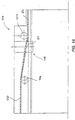
- Fig. 1
- eine Lineargetriebeeinheit nach einer ersten bevorzugten Ausführungsform der Erfindung in einer teilgeschnittenen Seitenansicht, die ein Gehäuse, eine darin aufgenommene Spindel mit einer zugehörigen Spindelmutter und mehreren Abstützungen zeigt,
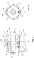
- Fig. 2
- die Lineargetriebeeinheit gemäß Fig. 1 in einer Frontansicht im Schnitt,
- Fig. 3
- eine Abstützung für die Spindel gemäß der Ausführungsform nach Fig. 1 in einem Längsschnitt, der die Spindel in einer Seitenansicht zeigt,
- Fig. 4
- die Abstützungen nach Figur 3 in einer Frontansicht, wobei das Gehäuse im Ausschnitt und die Spindel geschnitten dargestellt sind,
- Fig. 5
- eine Abstützung für die Spindel gemäß einer zweiten bevorzugten Ausführungsform der Erfindung in einem Längsschnitt, wobei die Spindel in einer Seitenansicht gezeigt ist,
- Fig. 6
- eine vergrößerte Ansicht der Abstützung in einer Teilschnittdarstellung entlang der Linie A-B in Fig. 5,
- Fig. 7
- die Abstützung gemäß den Fig. 5 und 6 in einer Frontansicht, wobei die Spindel und das Gehäuse im Ausschnitt jeweils geschnitten dargestellt sind,
- Fig. 8
- eine Abstützung für die Spindel gemäß einer weiteren Ausführungsform der Erfindung in einer Seitenansicht ähnlich Fig. 3 und Fig. 5,
- Fig. 9
- die Abstützung gemäß Fig. 8 in einer Frontansicht ähnlich den Fig. 4 und 7,
- Fig. 10
- die Abstützung gemäß den Fig. 8 und 9 in einer Draufsicht in Teilschnittdarstellung,
- Fig. 11
- eine Abstützung gemäß einer weiteren bevorzugten Ausführungsform der Erfindung in einer Seitenansicht ähnlich Fig. 3, 5 und 8,
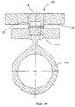
- Fig. 12
- die Abstützung gemäß Fig. 11 in einer Frontansicht ähnlich den Fig. 4, 7 und 9
- Fig. 13
- eine Abstützung gemäß einer weiteren bevorzugten Ausführungsform der Erfindung in einer Seitenansicht ähnlich den Fig. 3, 5, 8 und 11,
- Fig. 14
- die Abstützung gemäß Fig. 13 in einer Frontansicht ähnlich den Fig. 4, 7, 9 und 12
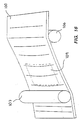
- Fig. 15
- ein das Gehäuse verschließendes Verschlußband und eine zugeordnete Bandführungseinrichtung mit einem Wölbemechanismus entsprechend einer bevorzugten Ausführungsform der Erfindung in einer Seitenansicht,
- Fig. 16
- eine schematische Darstellung des Verschlußbandes und der zugeordneten Bandführungseinrichtung mit dem Wölbemechanismus gemäß der Ausführungsform nach Fig. 15 in einer perspektivischen Ansicht,
- Fig. 17
- einen Wölbemechanismus für das Verschlußband in einer geschnittenen Frontansicht senkrecht zur Längsachse des Verschlußbandes,
- Fig. 18
- einen Wölbemechanismus für das Verschlußband in einer geschnittenen Frontansicht ähnlich Fig. 17 nach einer weiteren Ausführungsform mit einem Wölbedorn und einer Gegenrolle,
- Fig. 19
- eine Seitenansicht des Wölbemechanismus nach Fig. 18,
- Fig. 20
- eine Teilansicht des Gehäuses mit einer Aufnahmeausnehmung und dem darin aufgenommenen Verschlußband in einer perspektivischen Darstellung, und
- Fig. 21
- eine Frontansicht des Gehäuseausschnittes nach Figur 18 mit einer in die Aufnahmeausnehmung eingreifenden Führungswalze,
- Fig. 22
- eine Aufnahmeausnehmung mit einem darin eingeklemmten Verschlußband in einem Querschnitt,
- Fig. 23
- eine Aufnahmeausnehmung mit einem darin aufgenommenen Verschlußband in einer Ausführung mit rippenartigen Vorsprüngen in einem Öffnungsbereich in einer Querschnittsdarstellung ähnlich Figur 22 und
- Fig. 24
- eine Aufnahmeausnehmung mit einem darin aufgenommenen Verschlußband in einer Querschnittsdarstellung ähnlich Fig. 22 und 23 in einer Ausführungsform mit schwalbenschwanzförmigem Querschnitt der Ausnehmung.
- Fig. 1
- 2 shows a linear transmission unit according to a first preferred embodiment of the invention in a partially sectioned side view, which shows a housing, a spindle accommodated therein with an associated spindle nut and a plurality of supports,
- Fig. 2
- 1 in a front view in section,
- Fig. 3
- 2 shows a support for the spindle according to the embodiment according to FIG. 1 in a longitudinal section, which shows the spindle in a side view,
- Fig. 4
- the supports according to Figure 3 in a front view, the housing in the cutout and the spindle are shown in section,
- Fig. 5
- a support for the spindle according to a second preferred embodiment of the invention in a longitudinal section, the spindle being shown in a side view,
- Fig. 6
- 5 shows an enlarged view of the support in a partial sectional view along the line AB in FIG. 5,
- Fig. 7
- 5 and 6 in a front view, the spindle and the housing are each shown in section in section,
- Fig. 8
- 4 shows a support for the spindle according to a further embodiment of the invention in a side view similar to FIGS. 3 and 5,
- Fig. 9
- 8 in a front view similar to FIGS. 4 and 7,
- Fig. 10
- 8 and 9 in a plan view in partial sectional view,
- Fig. 11
- a support according to another preferred embodiment of the invention in a side view similar to FIGS. 3, 5 and 8,
- Fig. 12
- 11 in a front view similar to FIGS. 4, 7 and 9
- Fig. 13
- a support according to another preferred embodiment of the invention in a side view similar to FIGS. 3, 5, 8 and 11,
- Fig. 14
- 13 in a front view similar to FIGS. 4, 7, 9 and 12
- Fig. 15
- a side view of a closure tape closing the housing and an associated tape guide device with a buckling mechanism according to a preferred embodiment of the invention,
- Fig. 16
- 2 shows a perspective view of the fastener tape and the associated tape guide device with the arching mechanism according to the embodiment according to FIG. 15,
- Fig. 17
- a buckling mechanism for the fastener tape in a sectional front view perpendicular to the longitudinal axis of the fastener tape,
- Fig. 18
- 17 according to a further embodiment with an arching pin and a counter roller,
- Fig. 19
- 18 shows a side view of the arching mechanism according to FIG. 18,
- Fig. 20
- a partial view of the housing with a receiving recess and the fastener tape received therein in a perspective view, and
- Fig. 21
- 18 shows a front view of the housing cutout according to FIG. 18 with a guide roller engaging in the receiving recess,
- Fig. 22
- a receiving recess with a locking band clamped therein in a cross section,
- Fig. 23
- a receiving recess with a fastener tape received therein in an embodiment with rib-like projections in an opening area in a cross-sectional view similar to Figure 22 and
- Fig. 24
- a receiving recess with a fastener tape received therein in a cross-sectional view similar to FIGS. 22 and 23 in an embodiment with a dovetail-shaped cross section of the recess.
Fig. 1 zeigt eine Lineargetriebeeinheit, die als Grundbausteine
einen Rahmen 20, eine Spindel 41 und eine Spindelmutter
42 aufweist, die ein schlittenartiges Verschiebestück 43
antreibt. Der Rahmen 20 bildet ein formstabiles längliches
Gehäuse, das einen rohrförmigen Gehäuseabschnitt 21 und zwei
Lagerungsendabschnitte 22 und 23 besitzt, die, wie in Fig. 1
zu sehen ist, an den Enden des Gehäuseabschnittes 21 mit
diesem fest verbunden sind. Der Gehäuseabschnitt 21 ist als
Leichtmetallstrangußprofil ausgebildet und besitzt eine
Querschnittsform, die in Fig. 2 gezeigt ist.Fig. 1 shows a linear gear unit, the basic building blocks
a
Die Spindel 41 ist in dem Gehäuse aufgenommen und drehbar
gelagert. Hierzu sind in den Lagerungsendabschnitten 22,23
Wälzlager 24 und 25 vorgesehen, die jedoch auch durch entsprechende
Gleitlager ersetzt sein können. Die Spindel 41
tritt an einem Ende des Gehäuses aus diesem heraus und
besitzt an diesem Ende einen Antriebsabschnitt 26, an den
eine nicht weiter dargestellte Antriebsvorrichtung wie z.B.
ein Handrad oder ein Elektromotor angeschlossen werden kann.
Eine Dichtung 27 verhindert an dem an den Antriebsabschnitt
26 angrenzenden Ende des Gehäuses den Eintritt von Staub,
Schmutz oder dergleichen in das Innere des Gehäuses.The
Die Spindelmutter 42, die auf der Spindel 41 sitzt, ist mit
einem Spindelgewinde 28 in Eingriff und an dem Rahmen 20
längs verschieblich und drehfest geführt. Wie in Fig. 1 zu
sehen ist, ist die Spindelmutter 42 mittels eines Verbindungselementes
29, daß mit der Spindelmutter 42 fest verbunden,
insbesondere verschraubt ist, mit dem schlittenartigen
Verschiebestück 43 verbunden, wobei das Verbindungselement
29 sich durch einen im Gehäuse ausgebildeten Längsschlitz 30
erstreckt und gleichzeit die Spindelmutter 42 längs verschieblich
und drehfest führt.The
Wie in Fig. 2 zu sehen ist, umgreift das schlittenförmige
Verschiebestück 43 mit zwei Lagerungsabschnitten 31 den
gehäuseartigen Rahmen 20 und ist durch Gleitstücke 32, die
an den Lagerungsabschnitten 31 befestigt sind, in komplementären
Lagerungsbahnen verschieblich geführt.As can be seen in Fig. 2, the sledge-shaped
Das schlittenartige Verschiebestück 43, an dem linear anzutreibende
und zu positionierende Maschinenelemente befestigt
sein können, wird von der Spindelmutter 42 angetrieben, die
die rotatorische Antriebsbewegung der Spindel 41 in eine
translatorische Bewegung umsetzt.The sled-like sliding
Um Durchbiegungen, Orbitalbewegungen oder bei hohen Drehzahlen
Schwingungen der Spindel 41 zu vermeiden, sind zwischen
den Lagerungsendabschnitten 22, 23 auf beiden Seiten der
Spindelmutter 42 eine Mehrzahl von Abstützungen 33 in dem
Gehäuseabschnitt 21 aufgenommen, die die Spindel 41 an
mehreren Stellen zwischen den Lagerungsendabschnitten 22 und
23 gegenüber dem Gehäuseabschnitt 21 radial abstützen. Um
einerseits die Spindel 41 auch in einem Mittelbereich abzustützen
und andererseits den Verstellbereich der Spindelmutter
42 nicht zu beschränken, können die Abstützungen 33 auf
der Spindel 41 wandern. Der Antrieb der Abstützungen 33
erfolgt dabei direkt durch die Spindel 41.For deflections, orbital movements or at high speeds
Avoid vibrations of the
Wie in den Fig, 3 und 4 gezeigt, ist hierzu jede Abstützung
33 relativ zu dem Gehäuseabschnitt 21 längsverschieblich
und drehfest geführt und mit dem Spindelgewinde 28 in Eingriff
bringbar, so daß die Abstützung 33 durch Drehen der
Spindel 41 wie eine Mutter verschraubt wird und auf der
Spindel 41 wandert. Um die Abstützung 33 an einer gewünschten
Stelle anzuhalten und von dem mutterartigen Antrieb durch die
Spindel 41 abzukoppeln, sind Mittel 74 zum Lösen des Eingriffs
zwischen der Abstützung 33 und der Spindel 41 vorgesehen,
wie nachfolgend näher erläutert wird.As shown in Figures 3 and 4, this is any
Die Abstützung 33 weist, wie in Figur 3 gezeigt ist, zwei
zylindrische Abstützteile 34 und 35 auf, die jeweils eine
Spindelausnehmung 36 bzw. 37 besitzen und auf der Spindel 41
sitzen.As shown in FIG. 3, the
Die beiden Abstützteile 34 und 35 sind in einer im wesentlichen
zylindrischen Ausnehmung in dem Gehäuseabschnitt 21
aufgenommen und stützen sich an einer Innenwand derselben
radial ab. Wie in Fig. 4 zu sehen ist, ist an einem Außenumfang
der Abstützteile 34 und 35 jeweils ein Führungsvorsprung
38 ausgebildet, der sich in Spindellängsrichtung erstreckt
und in dem Längsschlitz 30 des Gehäuseabschnittes 21
eingreift, um ein Verdrehen des entsprechenden Abstützteiles
34 bzw. 35 zu verhindern. Wie in Fig. 3 zu sehen ist, sind
die beiden Abstützteile 34 und 35 durch eine Federeinrichtung
39 miteinander verbunden und derart relativ zueinander
vorgespannt, daß die Spindel 41 in den beiden Spindelausnehmungen
36 und 37 geklemmt ist und die beiden Abstützteile
34 und 35 mit dem Spindelgewinde 28 in Eingriff
sind. Die Federeinrichtung 39 weist zwei diametral gegenüberliegend
angeordnete Blattfederelemente 45 und 46 auf,
die in die beiden Abstützteile 34 und 35, die vorzugsweise
aus Kunststoff sind, eingegossen bzw. eingesteckt oder
eingeschraubt sind. Die Federelemente können jedoch auch in
anderer Weise mit den beiden Abstützteilen 34 und 35 verbunden
sein.The two
Während das in Fig. 3 obere Federelement 45 im wesentlichen
gerade ist, besitzt das zweite Federelement 46 einen bogenförmig
gekrümmten Abschnitt 47 der die beiden Enden des
Federelementes 46, mit denen dieses in den Abstützteilen
34 und 35 verankert ist, verbindet. Wie in Fig.
3 gezeigt ist, erstreckt sich der bogenförmige Abschnitt 47
in einer Längsnut 48, die in der Umfangsseite beider Abstützteile
34 und 35 ausgebildet ist, wobei der bogenförmige
Abschnitt 47 der Innenwand des Gehäuseabschnittes 21 zugewandt
ist und sich eine Sehne des bogenförmigen Abschnittes
47 im wesentlichen parallel zur Längsrichtung der Spindel 41
erstreckt. Die nachgiebige Verbindung der beiden Abstützteile
34 und 35 erlaubt es, daß die beiden Abstützteile
relativ zueinander beweglich sind und um eine Achse, die sich
im wesentlichen senkrecht zur Längsrichtung der Spindel 41
(in Fig. 3 senkrecht zur Zeichenebene) erstreckt, kippbar
sind. Die beiden Federelemente 45 und 47 spannen hierbei die
beiden Abstützteile 34 und 35 derart vor, daß diese zueinander
verkantet sind, d.h. daß die Achsen der Spindelausnehmungen
36 und 37 nicht koaxial und nicht parallel miteinander
sind, so daß die Spindel 41 geklemmt wird und die Spindelausnehmungen
36 und 37 das Spindelgewinde 28 greifen.While the
Wie in Fig. 3 gezeigt ist, sind die Oberflächen der Spindelausnehmungen
36 und 37 eben, d.h. es ist kein Gewinde in die
Spindelausnehmungen geschnitten, und sitzen auf Außenseiten
der Gewindeflanken des Spindelgewindes 28. Der mutterartige
Antrieb der Abstützteile 34 und 35 wird durch Reibschluß
zwischen den Außenseiten der Gewindeflanken des Spindelgewindes
28 und den Spindelausnehmungen 36 und 37 erzielt. Hierbei
erweist es sich günstig, daß durch das Verkanten der beiden
Abstützteile 34 und 35 aufgrund günstiger Hebelverhältnisse
auch mit kleinen Vorspannkräften relativ hohe Klemmkräfte
ausgeübt werden, um den Antrieb der Abstützteile zu gewährleisten.
Um ein Durchrutschen des Spindelgewindes 28 zu
verhindern, können, ohne daß dies in Fig. 3 explizit dargestellt
wäre, an der Oberfläche der Spindelausnehmungen 36
und 37 Mittel zur Verbesserung des Eingriffs zwischen den
Spindelausnehmungen 36 und 37 und dem Spindelgewinde 28
vorgesehen sein. Vorzugsweise können Vorsprünge, beispielsweise
eine oder mehrere schraubenförmige, insbesondere zu dem
Spindelgewinde 28 komplementäre Rippen in einer der oder in
beiden Spindelausnehmungen 36 und 37 ausgebildet sein, die
zwischen die Gewindeflanken des Spindelgewindes 28 eingreifen,
so daß die Antriebskraft der Spindel 41 nicht nur
reibschlüssig, sondern auch formschlüssig auf die Abstützteile
34 und 35 übertragen wird. Dies erweist sich insbesondere
bei Spindeln mit großen Gewindesteigungen von Vorteil.As shown in Fig. 3, the surfaces of the spindle recesses
36 and 37 even, i.e. there is no thread in that
Cut spindle recesses, and sit on outsides
the thread flanks of the
Um die Abstützung 33 an einer gewünschten Stelle anzuhalten
und von dem Antrieb durch die Spindel 41 abzukoppeln, weisen
die Lösemittel 74 zum Lösen des Eingriffs zwischen den
Abstützteilen 34 und 35 und der Spindel 41 ein Eingriffsteil
49 auf, das in Abhängigkeit der axialen Stellung der beiden
Abstützteile 34 und 35 auf der Spindel 41 mit der Federeinrichtung
39 in Eingriff gelangt. Das Eingriffsteil 49 ist
als Nockenteil mit einem im wesentlichen keilförmigen Nockenabschnitt
ausgebildet und an der Innenwand des Gehäuseabschnittes
21 befestigt. Das Eingriffsteil 49 ist dabei auf
dem Verschiebeweg angeordnet, den das zweite Federelement 46
überstreicht, wenn dieses auf der Spindel 41 wandert. Wie in
Fig. 3 zu sehen ist, läuft der bogenförmige Abschnitt 47 des
Federelementes 46 bei entsprechender Verschiebung der
Abstützung 33 auf das Eingriffsteil 49 wobei der keilförmige
Nockenabschnitt desselben den bogenförmigen Abschnitt 47 zu
dessen Krümmungsmittelpunkt hin (in Fig. 3 nach oben) drückt,
so daß sich die Krümmung des bogenförmigen Abschnittes 47
verkleinert und die Sehne desselben sich verlängert. Hierdurch
wird der Abstand zwischen den beiden Befestigungspunkten
des Federelementes 46 an den beiden Abstützteilen 34 und
35 größer und das Abstützteil 35 wird relativ zu dem anderen
Abstützteil 34 in Richtung des Pfeiles W geschwenkt, so daß
die Verkantung der beiden Abstützteile 34 und 35 beseitigt
und die Klemmung der Spindel 41 gelöst wird. Dementsprechend
bleibt die Abstützung 33 an der Stelle des Eingriffteiles 49
stehen und die Spindel 41 dreht sich ohne die Abstützung 33
anzutreiben.To stop the
Die Abstützung 33 wird mit der Spindel 41 wieder in Eingriff
gebracht, entweder durch eine in Antriebsrichtung gesehen von
hinten auflaufende weitere Abstützung oder durch ein Auflaufen
der Spindelmutter 42, so daß die entsprechende Abstützung
über das Eingriffsteil 49 hinweggeschoben wird und wieder
mit der Spindel 41 verklemmt.The
Das Prinzip der Klemmung und der entsprechenden Mittel, diese
zu lösen, kann selbstverständlich umgekehrt werden, indem die
beiden Abstützteile dann verkantet sind, wenn der bogenförmige
Abschnitt 47 des Federelementes 46 in eine gerade Stellung
gezwungen wird und der Eingriff zwischen der Abstützung
33 und der Spindel 41 gelöst ist, wenn der Abschnitt 47 zu
seiner entspannten Stellung hin ausballt. Dementsprechend
wäre das Eingriffsteil 49 eine in dem Verschiebeweg, den der
bogenförmige Abschnitt 47 überstreicht, ausgebildete Senke.The principle of clamping and the corresponding means, this
to solve can of course be reversed by the
both support parts are tilted when the
Die Fig. 5 bis 7 zeigen eine weitere Ausführungsform der
Abstützung, die im wesentlichen der zuvor beschriebenen
Ausführungsform entsprechend Fig. 3 und 4 ähnlich ist. Die
Abstützung 33 besitzt ebenfalls zwei Abstützteile 34 und 35,
die, wie in Fig. 7 zu sehen ist, jeweils durch einen von der
Innenwand des Gehäuseabschnittes 21 vorspringenden Führungsvorsprung
149 und eine entsprechende Führungsnut 50 in der
Umfangsseite der Abstützteile längsverschieblich und drehfest
geführt sind. Die beiden Abstützteile 34 und 35 sind ähnlich
wie in Fig. 3 und 4 um eine zur Längsrichtung der Spindel 41
senkrechte Achse kippbar und klemmen auf diese Weise das
Spindelgewinde 28. Die entsprechende Federeinrichtung 39
weist zwei Federelemente 45 und 46 auf, die die beiden
Abstützteile 34 und 35 relativ zueinander vorspannen. Das
Federelement 45 umgreift die beiden Abstützteile 34 und 35
spangenförmig, wobei ein Verbindungsabschnitt 51 des Federelementes
45 in einer nutförmigen Ausnehmung 52 in den
Umfangsflächen der beiden Abstützteile 34 und 35 aufgenommen
ist.5 to 7 show a further embodiment of the
Support essentially the same as that previously described
Embodiment corresponding to FIGS. 3 and 4 is similar. The
Das zweite Federelement 46 besitzt ähnlich der Ausführung
nach Fig. 3 einen bogenförmig gekrümmten Abschnitt, der die
beiden Endabschnitte des Federelementes 46, mit denen dieses
mit den beiden Abstützteilen 34 und 35 verbunden ist, verbindet.
Wie in den Fig. 5 bis 7 zu sehen ist, ist die Anordnung
des Federelementes 46 gegenüber der Anordnung nach Fig. 3
und 4 verdreht, wobei der bogenförmige Federabschnitt 47 in
einer Federnut 53 angeordnet ist, die parallel zur Spindellängsrichtung
in einer Umfangsseite der beiden Abstützteile
34 und 35 ausgebildet ist. In dieser Nut aufgenommen ist
ebenfalls ein Eingriffsteil 54, das schienenförmig in Spindellängsrichtung
von der Innenwand des Gehäuseabschnittes 21
vorspringt. Wie in Fig. 6 zu sehen ist, drückt das
schienenförmige Eingriffsteil 54 den bogenförmigen Abschnitt
47 des Federelementes 46 in eine gestreckte Form. Das schienenförmige
Eingriffsteil 54 besitzt eine Löseausnehmung 55,
in die der im entspannten Zustand bogenförmige Abschnitt 47
des Federelementes 46, wenn die Abstützung 33 in der
entsprechenden axialen Stellung ist, vorspringen kann, so daß
sich die wirksame Länge des Federelementes 46 ändert und die
Klemmung der Spindel 41 in den Spindelausnehmungen 36 und 37
der beiden Abstützteile 34 und 35 gelöst wird. Das Prinzip
der Klemmung dieser Ausführungsform entspricht ansonsten der
zuvor beschriebenen gemäß den Figuren 3 und 4, so daß eine
genaue Erläuterung nicht noch einmal notwendig erscheint.The
Die Fig. 8 bis 10 zeigen eine weitere Ausführungsform einer
Abstützung 33, die durch Klemmung der Außenseiten der Gewindeflanken
des Spindelgewindes 28 mutterartig angetrieben
und verstellt wird.8 to 10 show a further embodiment of a
Wie in den Fig. 8 und 9 gezeigt ist, weist die Abstützung 33
zwei Abstützteile 34 und 35 auf, die relativ zueinander
verdrehbar sind. Beide Abstützteile 34 und 35 besitzen eine
Spindelausnehmung 36 bzw. 37 und sitzen auf der Spindel 41.
Eines der beiden Abstützteile 34 ist mittels einer Längsnut
56 und einem Führungsvorsprung 57 an der Innenwand des
Gehäuseabschnittes 21 drehfest geführt, während das andere
Abstützteil 35 eine Längsnut 58 besitzt, die eine größere
Breite als der Führungsvorsprung 57 hat und eine begrenzte
Verdrehung des Abstützteiles 35 erlaubt. Zwischen den beiden
Abstützteilen 34 und 35 ist eine nabenartige Verbindung 60
vorgesehen, durch die die beiden Abstützteile beim Verdrehen
relativ zueinander um eine feste Drehachse 61 geführt sind.
Die Drehachse 61 ist parallel, jedoch exzentrisch zur
Längsachse der Spindelausnehmungen 36 und 37 (und hierdurch
exzentrisch zur Längsachse der Spindel 41), so daß ein
Verdrehen der beiden Abstützteile 34 und 35 ein Klemmen der
Spindel 41 in den beiden Spindelausnehmungen 36 und 37
bewirkt. Die Drehachse 61 liegt vorzugsweise koaxial mit der
Achse der zylindrischen Ausnehmung des Gehäuseabschnittes 21,
um ein Klemmen des Abstützteiles 35 beim Verdrehen zu
verhindern. Soll die Spindel 41 zentrisch in der
Gehäuseausnehmung des Gehäuseabschnittes 21 angeordnet sein
(in diesem Falle wäre die Drehachse 61 nicht koaxial mit der
Gehäuseachse), so wäre der Außendurchmesser des Abstützteiles
35 entsprechend zu reduzieren, um ein Klemmen mit dem
Gehäuseabschnitt 21 zu verhindern, bzw. müßte der Außenumfang
des Abstützteiles 35 derart gestaltet sein, daß dieser im
Spindelklemmzustand nicht mit der Innenwand des
Gehäuseabschnittes 21 klemmt.As shown in FIGS. 8 and 9, the
Die beiden Abstützteile 34 und 35 sind durch eine Federeinrichtung
62 relativ zueinander vorgespannt, um die Spindel
41 zu klemmen. Hierzu ist zwischen den beiden Abstützteilen
34 und 35 eine Drehfeder 63 angeordnet, die in einer Federausnehmung
64, die durch die Abstützteile 34 und 35 begrenzt
wird, aufgenommen ist und das Abstützteil 35 relativ zu dem
drehfest geführten Abstützteil 34 verdreht, derart, daß das
Spindelgewinde 28 in der Spindelausnehmung 37 geklemmt ist.
Hierdurch wird die Abstützung 33, wenn die Spindel 41 gedreht
wird, mutterartig angetrieben und verstellt, ähnlich wie bei
den bereits beschriebenen Ausführungen nach den Fig. 3 bis
7.The two
Um die Antriebsklemmung zwischen Spindel 41 und Abstützung
33 zu lösen, ist eine Drehsteuereinrichtung vorgesehen, die
die rotatorische Stellung der beiden Abstützteile 34 und 35
relativ zueinander in Abhängigkeit der axialen Stellung der
selben steuert. Die Drehsteuereinrichtung 75 weist, wie in
den Fig. 8 und 10 zu sehen ist, ein von der Innenwand des
Gehäuseabschnittes 21 vorspringendes Eingriffsteil auf, das
mit dem Gehäuseabschnitt 21 integral einstückig ausgebildet
oder mit diesem lösbar verbunden sein kann und als im wesentlichen
keilförmig profiliertes Nockenteil 79 ausgebildet ist,
wie insbesondere in Fig. 10 zu sehen ist. Das relativ zu dem
drehfesten Abstützteil 34 verdrehbare Abstützteil 35 besitzt
an seinem Außenumfang eine Drehsteuernut 77, die mit dem
keilförmig profilierten Nockenteil 79 in Eingriff gelangt,
wenn die Abstützung 33 auf das Nockenteil 79 läuft. Hierbei
verdreht das Nockenteil 79 das Abstützteil 35, wodurch sich
aufgrund der Exzentrizität die Klemmung der Spindel 41 in
der Spindelausnehmung 37 löst. Ähnlich der Drehsteuernut 77
besitzt das drehfeste Abstützteil 34 an seinem Außenumfang
eine Durchgangsnut 76, die in Umfangsrichtung fluchtend mit
dem Nockenteil 79 angeordnet ist, so daß die Abstützung 33
über das Nockenteil 79 hinweggeschoben werden kann. Während
wie in Fig. 10 gezeigt ist, die Drehsteuernut 77 und die
Durchgangsnut 76 im Spindelklemmzustand in Umfangsrichtung
zueinander versetzt sind, wird das Abstützteil 35, wenn
dieses auf das Nockenteil 79 geschoben wird, derart verdreht,
daß die Durchgangsnut 76 und die Drehsteuernut 77 miteinander
fluchten. Aus den Abstützstellungen, die durch die
entsprechenden Nockenteile definiert sind, werden die
Abstützungen jeweils, ähnlich den zuvor beschriebenen
Ausführungen, entweder durch eine nachfolgende Abstützung
oder die Spindelmutter geschoben.To the drive clamp between
Die exzentrische Klemmung der Spindel 41 erlaubt aufgrund
der günstigen Umsetzung der Federvorspannkraft durch die
exzentrische Nabenverbindung die Spindel 41 mit hohen Klemmkräften
zu klemmen. The eccentric clamping of the
Es ist anzumerken, daß das Prinzip der Drehsteuereinrichtung
auch umgekehrt werden könnte, ohne daß dies explizit in den
Zeichnungen dargestellt ist. In diesem Falle besäße das
Abstützteil 35 einen Eingriffsvorsprung, beispielsweise
einen von dem Außenumfang vorspringenden Stift, der in eine
Drehsteuernut in der Innenwand des Gehäuseabschnittes 21
eingreifen würde. An den Stellen, an denen die Abstützung 33
von dem Spindeltrieb 41 abzukoppeln wäre, müßte die
Drehsteuernut eine entsprechende Kurve definieren, um das
Abstützteil 35 zu verdrehen.It should be noted that the principle of the rotary control device
could also be reversed without this being explicitly stated in the
Drawings is shown. In this case, that would be
Die Fig. 11 und 12 zeigen eine weitere Ausführung, bei der
eine Abstützung 33 durch Klemmen des Spindelgewindes 28
angetrieben wird. Die Abstützung 33 weist zwei Abstützabschnitte
80 und 81 auf, die jeweils halbringförmig sind und
die Spindel 41 halbschalenartig umgreifen. Zusammengesetzt,
wie in Fig. 12 zu sehen ist, ergänzen sich die beiden Abstützteile
80 und 81 zu einer im wesentlichen ringförmigen
Abstützung, die in einer zylindrischen Ausnehmung des Gehäuseabschnittes
21 aufgenommen und drehfest geführt ist. Die
beiden Abstützteile 80 und 81 besitzen eine jeweils halbzylindrische
Spindelausnehmung 82 bzw. 83, die zusammen eine
Spindelausnehmung begrenzen, in der die Spindel 41 aufgenommen
ist und klemmbar ist. Um die beiden Abstützteile 80
und 81 vorzuspannen, um die Spindel 41 zu klemmen, d.h. die
beiden halbzylindrischen Spindelausnehmungen 82 und 83 gegen
die Außenseite der Gewindeflanken des Spindelgewindes 28 zu
drücken, ist eine Spannfeder 84 vorgesehen, die klammerförmig
ausgebildet und in entsprechenden Ausnehmungen in beiden
Abstützteilen 80 und 81 aufgenommen ist, wie in Fig. 12 zu
sehen ist.11 and 12 show a further embodiment in which
a
Anstelle der Spannfeder 84 könnte die Abstützung 33 auch
einteilig ausgeführt sein, wobei diese lediglich an einer
Seite geschlitzt wäre und die Spannkraft, um die Spindel zu
klemmen, durch elastische Verformung der Abstützung aufgebracht
werden könnte.Instead of the
Im Spindelklemmzustand wird die Abstützung 33 ähnlich den
zuvor beschriebenen Ausführungen durch Eingriff mit dem
Spindelgewinde 28 angetrieben. Die Innenseite der Spindelausnehmungen
82 und 83 kann ggf. auch rippenartige Gewindevorsprünge
aufweisen, um den Eingriff zwischen den beiden
Abstützteilen 80 und 81 mit der Spindel 41 zu verbessern.In the spindle clamping state, the
Um die Klemmung des Spindelgewindes 28 zu lösen und die
Abstützung 33 von dem Antrieb durch die Spindel 41 abzukoppeln,
ist eine Aufspreizeinrichtung 85 vorgesehen, die
die Spindelausnehmungen 82 und 83 aufspreizt, wobei die
beiden Abstützteile 80 und 81 um eine Achse, die im wesentlichen
durch das Federelement 84 bestimmt ist, aufgeschwenkt
werden. Die Aufspreizeinrichtung 85 weist ein fest
mit dem Gehäuseabschnitt 21 verbundenes Aufspreizteil 86 auf,
das als im wesentlichen doppelkeilförmiges oder elliptisches
Nockenteil ausgebildet ist. Die beiden Abstützteile 80 und
81 besitzen, wie in Figur 12 zu sehen ist, an ihrem Außenumfang
jeweils eine Ausnehmung 186 und 187, die zusammen eine
Längsnut bilden, in die der Spreiznocken 86 eingreifen kann,
wenn die Abstützung 33 über den Spreiznocken 86 geschoben
wird. Wie in Figur 11 zu sehen ist, ist in den Ausnehmungen
186 und 187 jeweils ein bogenförmig gekrümmtes Blattfederelement
angeordnet, wobei die bogenförmigen Abschnitte der
Federelemente 88, 89 einander zugewandt sind, so daß der
Spreiznocken 86 zwischen diese Federelemente 88, 89 eingreift
und die Abstützteile 80 und 81 auseinanderdrückt,
wenn diese über den Spreiznocken 86 wandern. Hierdurch wird
der Eingriff zwischen der Abstützung 33 und der Spindel 41
gelöst, so daß die Abstützung angehalten wird und die Spindel
sich drehen kann ohne die Abstützung 33 anzutreiben.To release the clamping of the
Die Fig. 13 und 14 zeigen eine Ausführung einer Abstützung
33, die durch das Spindelgewinde 28 nicht reibschlüssig,
sondern formschlüssig angetrieben wird. Die Abstützung 33
besitzt ein im wesentlichen ringförmiges Abstützteil 90, das
eine Spindelausnehmung 91 besitzt, in der die Spindel 41
verschieblich aufgenommen ist. Die Abstützung 33 besitzt
ferner ein schieberartiges Eingriffsteil 92, das in einer
radial verlaufenden Ausnehmung 93 in dem Abstützteil 90
radial verschieblich geführt ist. Das Eingriffsteil 92 weist
einen konkaven, zu der Spindel 41 komplementären Eingriffsabschnitt
93 auf, der mit dem Spindelgewinde 28 in Eingriff
bringbar ist. Hierzu ist vorzugsweise in den Eingriffsabschnitt
93 ein zu dem Spindelgewinde 28 komplementäres
Gewinde eingebracht, durch das das Eingriffsteil 92, wenn es
gegen die Spindel 41 geschoben wird, mit dieser in Eingriff
ist. Wie in Fig. 13 zu sehen ist, steht das Eingriffsteil 92
im Eingriffszustand an der Innenwand des Gehäuseabschnittes
21 an. Die Lösemittel zum Lösen des Eingriffes zwischen der
Abstützung 33 und der Spindel 41 weisen wie in Fig. 13
gezeigt ist, eine Lösesenke 96 auf, in die das Eingriffsteil
92 verschiebbar ist, so daß der Eingriffsabschnitt 93 mit
dem Spindelgewinde 28 außer Eingriff gerät. Dies kann durch
Schwerkraft, vorzugsweise jedoch durch eine Federeinrichtung
erreicht werden, die das Eingriffsteil 92 gegen die Innenwand
des Gehäuseabschnitts 21 drückt, jedoch in den Figuren
nicht explizit dargestellt ist.13 and 14 show an embodiment of a
Diese Ausführung der Abstützung zeichnet sich durch ihren
besonders einfachen Aufbau aus und gewährleistet darüber
hinaus einen sicheren Eingriff zwischen der Abstützung und
der Spindel, der ein Durchrutschen der Spindel 41 verhindert.This version of the support is characterized by its
particularly simple structure and ensures
secure engagement between the support and
the spindle, which prevents the
Die Wirkungsweise der aktiv durch die Spindel 41 angetriebenen
Abstützungen 33 ist insbesondere aus Fig. 1 verständlich.
Die Spindel 41 wird an ihrem Antriebsabschnitt 26 von
Hand oder einem Elektromotor oder dergleichen rotatorisch
angetrieben. Die rotatorische Bewegung der Spindel 41 wird
durch die Spindelmutter 42, die mit dem Spindelgewinde 28 in
Eingriff ist und durch das Verbindungselement 29 drehfest
geführt ist, in eine translatorische Bewegung umgewandelt,
d.h. die Spindelmutter 42 wird in dem Gehäuse entsprechend
Figur 1 nach links bzw. rechts verschoben. Hierdurch wird das
schlittenartige Verschiebestück 43, mit dem ein zu verstellendes
Maschinenelement verbunden sein kann, ebenfalls linear
hin- und herbewegt. Wie später noch näher erläutert werden
wird, ist der Längsschlitz 30, durch den sich das Verbindungselement
29 erstreckt, durch ein Verschlußband 100
verschlossen, wobei das Verschlußband entsprechend der
Bewegung der Spindelmutter und des Verschiebstückes im
Bereich des Verbindungselementes reißverschlußartig geöffnet
bzw. geschlossen wird. In Bewegungsrichtung gesehen wird das
Verschlußband vor dem Verbindungselement, das sich durch den
Längsschlitz erstreckt, aus einer entsprechenden Verschlußnut
herausgeführt und hinter dem Verbindungselement in diese Nut
wieder hineingeführt.The mode of operation of those actively driven by the
In einer Ausgangsstellung, in der die Abstützungen 33 durch
die entsprechenden Lösemittel außer Eingriff mit der Spindel
41 gehalten werden, werden die Abstützungen 33 in der entsprechenden
Stellung gehalten und die Spindel 41 kann gedreht
werden, um die Spindelmutter 42 anzutreiben. Bewegt sich die
Spindelmutter 42 nur in einem kleinen Verstellbereich, werden
die Abstützungen 33 nicht bewegt. Wird die Spindelmutter 42
jedoch darüber hinaus verschoben, stößt die Spindelmutter 42
gegen die zunächst ruhende Abstützung 33 und verschiebt diese
in Richtung der Spindelmutterbewegung. Hierdurch wird die
entsprechende Abstützung 33 von dem entsprechenden mechanischen
Lösemittel, das mit dem Gehäuseabschnitt 21 fest
verbunden ist, geschoben, wodurch die Abstützungen 33 mit der
Spindel 41 in Eingriff gerät und durch diese selbst schraubenartig
angetrieben wird. Wandert die Spindelmutter 42 auch
über die nächstfolgende Abstützung 33 hinaus, so wird diese
Abstützung ebenfalls verschoben und gerät mit der Spindel 41
in Eingriff. Wird die Spindel 41 gegenläufig gedreht und die
Spindelmutter 42 entsprechend rückwärts verschoben, werden
die Abstützungen, die das Spindelgewinde 28 klemmen, bzw. mit
diesem in Eingriff sind, ebenfalls durch die Spindel 41
rückwärts angetrieben und folgen der Spindelmutter. Laufen
die Abstützungen 33 über die erste Raststelle, so wird die
erste Abstützung durch das entsprechende Lösemittel von dem
Spindelgewinde außer Eingriff gebracht und angehalten. Die
nachfolgende Abstützung schiebt die angehaltene Abstützung
jedoch weiter und wird selbst an der entsprechenden Raststelle
angehalten. Die weiter geschobene Abstützung wird an
der nächsten Raststelle entsprechend angehalten.In a starting position, in which the
Die Verschiebbarkeit der Abstützungen entsprechend der verschiedenen Ausführungen wird also dadurch bewirkt, daß die Abstützungen mit der Spindel in Eingriff bringbar sind und durch die Spindel selbst angetrieben werden und daß an Raststellen, an denen die Abstützungen angehalten werden sollen, Lösemechanismen vorgesehen sind, die den Eingriff zwischen der Abstützung und der Spindel lösen, wobei die Abstützung mit dem Lösemechanismus in Eingriff gerät, indem die Abstützung auf diesen geschoben wird. Der Lösemechanismus wird also durch die Verschiebung der Abstützung selbst aktiviert. The displaceability of the supports according to the different versions is thus effected in that the Supports can be brought into engagement with the spindle and are driven by the spindle itself and that at Resting points at which the supports are stopped should, release mechanisms are provided, the engagement loosen between the support and the spindle, the Support engages with the release mechanism by the support is pushed onto this. The release mechanism is so by shifting the support itself activated.
Wie in Fig. 1 gezeigt ist, weist der Spindelgehäuseabschnitt
21 einen Längsschlitz 30 auf, durch den sich das Verbindungselement
29 erstreckt. Um das Eindringen von Staub oder
Schmutz in das Innnere des Gehäuses zu verhindern, ist ein
elastisches Verschlußband 100 vorgesehen, das den Längsschlitz
30 beidseitig des Verbindungselementes 29 verschließt.
Hierbei ist in dem Gehäuseabschnitt 21, wie in
Figur 20 gezeigt ist, an die Längsnut 30 angrenzend eine
Aufnahmeausnehmung 101 ausgebildet, in der das Verschlußband
100 aufgenommen ist. Wie in Fig. 21 gezeigt ist, besitzt die
Aufnahmeausnehmung 101 grundsätzlich einen Boden 102, in den
der Längsschlitz 30 mündet, und zwei gegenüberliegende
Seitenwände 103, so daß die Aufnahmeausnehmung 101 eine im
wesentlichen nutförmige Gestalt hat.As shown in Fig. 1, the spindle housing portion has
21 a
Um den Längsschlitz 30 möglichst dicht zu verschließen, ist
vorzugsweise eine Breite V der Aufnahmeausnehmung 101, d.h.
der Abstand der beiden Seitenwände 103 voneinander, kleiner
als die Breite des Verschlußbandes 100 im entspannten Zustand.
Wie in Fig. 22 gezeigt ist, wölbt sich daher das
elastische Verschlußband 100 und drückt sich aufgrund seiner
Eigenspannung gegen die Seitenwände 103, so daß der Längsschlitz
30 dicht gegenüber dem Gehäuseäußeren abgedichtet
ist.In order to close the
Wie in Fig. 23 zu sehen ist, kann die Breite V der Aufnahmeausnehmung
jedoch auch gleich oder größer der Breite des
elastischen Verschlußbandes 100 im entspannten Zustand sein,
wobei in einem Öffnungsbereich der nutförmigen Ausnehmung
101 zu der Gehäuseaußenseite an den beiden Seitenwänden 103
jeweils ein rippenartiger Vorsprung 104 ausgebildet ist,
deren Abstand voneinander kleiner ist als die Breite des
Verschlußbandes, um ein unbeabsichtigtes Herausrutschen des
Verschlußbandes zu verhindern. Die Breite der Ausnehmung 101
gemäß der Ausführung nach Fig. 23 kann jedoch ebenfalls
kleiner sein als die Breite des Verschlußbandes 100, wodurch
die Abdichtung weiter verbessert wird. Der Abstand U der
Vorsprünge von dem Boden 102 ist vorzugsweise größer als die
Dicke T des Verschlußbandes 100, um ein Ein- und Ausfädeln
des Verschlußbandes 100 in die Aufnahmeausnehmung 101 zu
verbessern, wie später noch erläutert werden wird.As can be seen in Fig. 23, the width V of the receiving recess
but also equal to or greater than the width of the
Um das Verschlußband 100 sicher in der Ausnehmung 101 aufzunehmen
und den Längsschlitz 30 wirksam gegenüber der Umgebung
abzudichten, kann die Aufnahmeausnehmung 101 auch einen
schwalbenschwanzförmigen Querschnitt besitzen, wie in Fig. 24
dargestellt ist. Der Öffnungsbereich der schwalbenschwanförmigen
Ausnehmung 101 ist auch in dieser Ausführungsform
schmaler als das elastische Verschlußband 100 breit ist,
so daß ein unbeabsichtigtes Herausrutschen verhindert und
eine effektive Abdichtung gewährleistet ist.To securely hold the
Wie in Fig. 1 zu sehen ist, ist mit dem Verbindungselement
29 bzw. mit dem schlittenartigen Verschiebestück 43 ein
Verschlußmechanismus verbunden, der das elastische Verschlußband
100 in die Aufnahmeausnehmung 101 drückt bzw. aus dieser
heraus entfernt, um das Verschlußband jeweils an der Stelle,
an der sich das Verbindungselement 29 durch den Längsschlitz
30 erstreckt, aus der Aufnahmeausnehmung 101 zu entfernen
und über das Verbindungselement 29 zu führen. Der Verschlußmechanismus
weist eine Bandführungseinrichtung 105 auf, die
mit dem Verbindungselement 29 mitbewegt wird.As can be seen in Fig. 1, is with the connecting element
29 or with the slide-like sliding
Wie schematisch in Fig. 15 gezeigt ist, weist die Bandführungseinrichtung
105 zwei drehbare Führungswalzen 106 und
107 auf, von denen eine das Führungsband 100 außerhalb der
Aufnahmeausnehmung 101 auf der Außenseite des Gehäuses führt,
während die andere Führungswalze 107, die mit der gegenüberliegenden
Seite des Verschlußbandes 100 (bezogen auf die
erste Führungswalze 106) in Berührung ist, das Verschlußband
100, wie in den Fig. 15 und 21 zu sehen ist, in die Aufnahmeausnehmung
101 hineindrückt.As shown schematically in Fig. 15, the tape guide means
105 two
Um das Ein- und Ausfädeln des Verschlußbandes 100 in die
nutförmige Ausnehmung 101 zu erleichtern, ist zwischen den
beiden Führungswalzen 106 und 107 eine Einrichtung vorgesehen,
die die wirksame Bandbreite des Verschlußbandes 100
verringert, insbesondere mindestens bis auf die Öffnungsbreite
der Aufnahmeausnehmung 101 verringern. Hierfür ist
zwischen den beiden Führungswalzen ein Wölbemechanismus 108
angeordnet, der das Verschlußband 100 zwischen den beiden
Führungswalzen 106 und 107 wölbt, wie dies schematisch in
Fig. 16 dargestellt ist.To thread the threading of the
Wie in Fig. 17 gezeigt, besitzt der Wölbemechanismus 108
einen Wölbungskeil 109 der eine quer zur Längsrichtung des
Verschlußbandes 100 konvex gewölbte Druckfläche 110 aufweist,
die wie in Fig. 15 zu sehen ist, zur Längsrichtung
der Aufnahmeausnehmung 101 geneigt ist, um gegen die dem
Längsschlitz 30 zugewandte Seite des Verschlußbandes 100 in
einem Mittelbereich des Verschlußbandes zu drücken. Auf der
gegenüberliegenden Seite des Verschlußbandes ist ein Gegenstück
111 angeordnet, das zwei parallele vorspringende
Drucknasen 112 aufweist, die auf die gegenüberliegende Seite
des Verschlußbandes 100 in deren Randbereich drücken, so daß
sich das Verschlußband 100 infolge der Druckeinwirkung des
Wölbungskeils 109 und des Gegenstückes 111 wölbt, wie in
Fig. 17 zu sehen ist. Die Drucknasen 112 sind entsprechend
der Druckfläche 110 des Wölbungskeils 109 geneigt zur Längsrichtung
der Aufnahmeausnehmung und parallel zu der Längsrichtung
der gewölbten Druckfläche 110. As shown in FIG. 17, the
Der Druck- bzw. Wölbungskeil 109 kann mit dem Verbindungselement
29 verbunden sein und kann sich zusätzlich durch eine
Keilabstützung 113 auf der Spindel 41 abstützen. Der Wölbungskeil
sowie die Bandführungsvorrichtung könnten mittels
der Abstützung 113 auch durch die Spindel selbst angetrieben
werden.The
Wie in Fig. 16 schematisch dargestellt ist, drückt der
Wölbungskeil 109 in einem Bereich des Verschlußbandes 100
von unten gegen dieses, der zwischen den beiden Führungswalzen
107 und 106 liegt und insbesondere von beiden Führungswalzen
beabstandet ist. Hierdurch wird die Tatsache berücksichtigt,
daß ein elastisches Band normalerweise nur einachsig
gebogen werden kann. Wie in Fig. 16 dargestellt, wird
das Verschlußband 100 an der Führungswalze 107 zunächst nach
oben (im Sinne der Fig. 16) umgelenkt, und nach der Umlenkung
durch den Wölbemechanismus 108 um eine Achse parallel
zur Längsrichtung des Verschlußbandes gebogen bzw. gewölbt,
um die wirksame Breite des Verschlußbandes zu verringern und
das Ein- bzw. Ausfädeln des Bandes in die bzw. aus der
Ausnehmung 101 zu erleichtern. Nach der Wölbung des Bandes im
Bereich des Wölbungskeiles 109 wird das Band in einem hiervon
beabstandeten Bereich durch die Führungswalze 106 umgelenkt.
Der Abstand des Wölbemechanismuses von beiden Führungswalzen
verhindert wirkungsvoll eine zweiachsige Biegung des Verschlußbandes
und einen vorzeitigen Verschleiß des Bandes.As shown schematically in Fig. 16, the
Eine weitere Ausführungsform des Wölbemechanismus 108 ist in
den Fig. 18 und 19 gezeigt, wobei anstelle des Wölbekeils ein
Wölbedorn 209 verwendet wird, der gegen die dem Längsschlitz
30 zugewandte Seite des Verschlußbandes 100 in dessen Mittelbereich
drückt. Auf der gegenüberliegenden Seite des Verschlußbandes
ist eine Gegenrolle 211 angeordnet, die drehbar
gelagert ist und in den Randbereichen 2 abgerundete Vorsprünge
212 besitzt, die auf die gegenüberliegende Seite des
Verschlußbandes 100 drücken. Wie in Fig. 19 gezeigt, wird der
Druckdorn 209 im wesentlichen durch einen Stift gebildet, der
gekröpft ist, um das Verschlußband 100 sanft in die gewölbte
Form zu drücken.Another embodiment of
Die Wirkungsweise des Verschlußbandes und der Bandführungseinrichtung
ist aus Fig. 1 ersichtlich. Wenn die Spindel
gedreht wird und dementsprechend die Spindelmutter 42 in
Fig. 1 nach links oder rechts bewegt wird, muß der Längsschlitz
30 im Bereich des Verbindungselementes 29 jeweils
geöffnet sein. In diesem Bereich wird das Verschlußband
außerhalb der Aufnahmeausnehmung geführt und an dem Verbindungselement
29 vorbeigelenkt. Entsprechend der Bewegung der
Spindelmutter 42 nach links oder rechts wird die Bandführungseinrichtung
synchron mit der Spindelmutter nach links
oder rechts bewegt, wodurch das Verschlußband in Bewegungsrichtung
gesehen vor dem Verbindungselement 29 aus der
Aufnahmeausnehmung 101 herausgeführt (unter Wölbung bzw.
Verdrehung des Verschlußbandes) und hinter dem Verbindungselement
29 wieder in die Aufnahmeausnehmung (wiederum unter
Wölbung bzw. Verdrehung des Bandes) hineingedrückt. Wie in
Fig. 1 zu sehen ist, wird die Bandführungseinrichtung und
der Wölbemechanismus synchron mit dem Verbindungselement 29
bzw. der Spindelmutter 42 mitgeführt, so daß das Verschlußband
100 reißverschlußartig ein- und ausgefädelt wird. Die
Bandführungseinrichtung und der Wölbemechanismus sind, obwohl
in Fig. 1 nur auf einer Seite des Verbindungselementes 29
dargestellt, auf beiden Seiten des Verbindungselementes 29
vorgesehen.The operation of the fastener tape and the tape guide
can be seen from Fig. 1. If the spindle
is rotated and accordingly the
Das Spindelgetriebe ist durch das Verschließen des Längsschlitzes
30 wirksam vor dem Eindringen von Staub und Schmutz
geschützt. Hierbei liegt das Prinzip zugrunde, ein elastisches
Verschlußband in eine Aufnahmeausnehmung, deren
Öffnungsbereich schmäler ist als die Breite des Verschlußbandes,
einzuführen, wobei die wirksame Breite des Verschlußbandes
verringert wird, um das Einführen zu erleichtern und
Verschleiß des Bandes zu verhindern. Neben der Lösung, das
Band zu wölben, könnte die wirksame Breite auch dadurch
verringert werden, daß das Band beispielsweise durch Kippen
der Führungswalze 106 verdreht und dadurch aus der Ausnehmung
101 herausgedreht wird. Dadurch könnte das Verbindungselement
29 besonders einfach gestaltet sein, da das Verschlußband
nicht über dieses hinweg sondern an diesem vorbei
geführt werden kann. Dadurch, daß die wirksame Breite des
Bandes beim Ein- und Ausfädeln des selben verringert wird,
ergibt sich der Vorteil, daß ein einfaches und billiges
Verschlußband ohne besonderen Querschnitt verwendet werden
kann und das elastische Andrücken des Bandes gegen die
Seitenwände der Aufnahmeausnehmung ein dichtes Verschließen
des Längsschlitzes 30 gewährleistet.The spindle gear is through the closing of the
Claims (21)
- Linear drive unit with a frame, a spindle (41) mounted in rotary manner on the frame (20) and having an associated spindle nut (42), as well as at least one support (33) for the spindle (41), the support (33) being longitudinally adjustable relative to the frame (20), characterized in that the support (33) is engageable with the spindle (41) for longitudinal adjustment and means (74) are provided for releasing the engagement between the support and the spindle, the support (33) having a spindle recess (36, 37; 82, 83; 91), in which is received the spindle (41) in such a way that an outside of a spindle thread (28) is engageable with the spindle recess.
- Linear drive unit according to claim 1, characterized in that the support (33) can be brought into clamping engagement with the spindle thread (28).
- Linear drive unit according to claim 1, characterized in that the support (33) can be positively engaged with the spindle thread (28).
- Linear drive unit according to at least one of the claims 1 to 3, characterized in that the frame (20) has a housing section (21), which embraces the spindle (41), the support (33) being guided in non-rotary, longitudinally displaceable manner preferably on an inner wall of the housing section.
- Linear drive unit according to at least one of the claims 1 to 4, characterized in that the support (33) has a first and a second support part (34, 35; 80, 81), which are interconnected and movable relative to one another, particularly between a first position in which the spindle (41) is engageable with at least one of the support parts and a second position in which the engagement is eliminated.
- Linear drive unit according to at least one of the claims 1 to 5, characterized in that a spring mechanism (39; 62) is provided for pretensioning the support (33) in its engagement position and preferably the release means (74) are engageable with the spring mechanism (39).
- Linear drive unit according to at least one of the claims 1 to 6, characterized in that the release means have an engagement part (49; 54), which is engageable with the support (33) as a function of the longitudinal position thereof and is preferably firmly connected to the frame (20), particularly with an inner wall of the housing section (21).
- Linear drive unit according to at least one of the claims 5 to 7, characterized in that the two support parts (34, 35) in each case have a spindle recess (36, 37) in which the spindle (41) is received and are successively arranged in the spindle longitudinal direction, the support parts can be brought into and out of a mutual coaxial arrangement with the longitudinal axes of the spindle recesses.
- Linear drive unit according to at least one of the preceding claims 6 to 8, characterized in that the support (33) is provided on an inside facing the spindle (41) with at least one more particularly rib-like projection for positive engagement with the spindle thread (28).
- Linear drive unit according to at least one of the claims 5 to 9, characterized in that the two support parts (34, 35) can be tilted relative to one another about an axis substantially perpendicular to the longitudinal direction of the spindle (41) and are pretensioned by a spring mechanism (39) in a mutually tilted position and preferably between the two support parts are provided two diametrically facing spring elements (45, 46), whereof at least one has an arcuately curved portion (47) in the relaxed state.
- Linear drive unit according to claim 10, characterized in that the curved portion (47) of the spring element (46) is engageable with the engagement part (49) of the release means (74), in which in the engagement state the curved portion preferably has a smaller curvature than in the non-engagement state and in particular in the spindle longitudinal direction is positioned on a circumferential side of the support (33) and faces an inner wall of the housing section (21) and the engagement part (49) has a wedge-shaped cam section in the spindle longitudinal direction projecting from the inner wall.
- Linear drive unit according to claim 11, characterized in that the curved portion (47) of the spring element (46) is engageable with an engagement part (54) of the release means (74) and the engagement part (54) has a rail section extending in the spindle longitudinal direction and which has at least one recess (55) for receiving the curved portion (47), in which the curved portion in the spindle longitudinal direction is preferably placed in a groove (53) in a circumferential side of the support (33) and the rail section engages in the groove.
- Linear drive unit according to at least one of the claims 5 to 9, characterized in that at least one of the support parts (34, 35) is rotatable relative to the other about an axis parallel and eccentric to the longitudinal axis of the spindle (41) and between the two support parts is preferably provided a torsion spring device (62) for pretensioning the two support parts relative to one another and preferably a rotation control device (75) for controlling the rotary position of the two support parts (34, 35) relative to one another is provided as a function of the axial position thereof and at least one of the support parts (35) has associated with it a twisting device (77, 78), which preferably has a substantially wedge-shaped, profiled cam part located on an inner wall of the housing section (21) and an engagement element provided on the support part (35), more particularly a longitudinal groove.
- Linear drive unit according to at least one of the claims 5 to 9, characterized in that the support (33) has two half shell-like support sections (80, 81), which are tensioned relative to one another radially against the spindle (41) and at least on one side of the spindle are separated from one another and the release means have an expanding device (85), which preferably has a longitudinal groove (88, 89) between the two support sections (80, 81) and an expanding part (86), particularly an expanding cam engageable with the longitudinal groove, for expanding the support sections.
- Linear drive unit according to at least one of the claims 1 to 14, characterized in that several supports (33) are provided, preferably on both sides of the spindle nut (42).
- Linear drive unit according to at least one of the preceding claims 1 to 15, characterized in that a housing (21) receiving the spindle (41) with the associated spindle nut (42) has an elongated slot (30) through which extends a connecting element (29) connected to the spindle nut and an elastic closing band (100) is provided for closing the elongated slot, the housing having a reception recess (101) for receiving the closing band, whose opening area has a smaller width (V) towards the housing outside than the closing band and a band guiding device (105) is provided for reducing the effective band width.
- Linear drive unit according to claim 16, characterized in that the band guiding device (105) has a cambering mechanism (108) for guiding the closing band (100) in a cambered state during threading and unthreading with respect to the reception recess (101) and preferably the cambering mechanism (108) has a cambering wedge (109), which is in contact with the closing band (100) at least in a central area of said band and is preferably located on a closing band side facing the elongated slot (30), whilst having a counterpart (111), which is located on the closing band side opposite to the cambering wedge and is at least in contact with marginal areas of the closing band, that preferably the cambering wedge (109) has a pressure surface (110) convexly cambered transversely to the longitudinal direction of the closing band (100) and which is preferably inclined to the longitudinal direction of the reception recess (101) and the counterpart (111) preferably has two U-shaped projecting pressure noses (112) extending parallel to a longitudinal direction of the cambering wedge (109), and that the cambering mechanism (108) in the closing band longitudinal direction is spaced from and positioned between the guide elements (106, 107).
- Linear drive unit according to claim 16 or 17, characterized in that on either side of the opening area of the reception recess (101), the band guiding device (105) has in each case at least one guide element (106, 107), particularly a rotary guide roller and preferably one of the guide elements (107) extends into the reception recess (101).
- Linear drive unit according to at least one of the claims 16 to 18, characterized in that the band guiding device (105) is movable in the spindle longitudinal direction, preferably synchronously with the spindle nut (42).
- Linear drive unit according to at least one of the claims 16 to 19, characterized in that the closing band (100) is guided past the connecting element (29) and received in the reception recess (101) on either side thereof and preferably on both sides of the connecting element (29) is provided a band guiding device (105).
- Linear drive unit according to at least one of the claims 16 to 20, characterized in that the reception recess (101) has a substantially groove-like design with two side walls (103) and a base (102), to which the elongated slot (30) is connected, the side walls (103) in an end region facing the base in each case have in particular a rib-like projection (104) and preferably the,spacing (U) of the projections (104) from the base (102) of the reception recess (101) is greater than the thickness (T) of the closing band (100) and preferably the mutual spacing (V) of the two side walls (103) exceeds the width of the closing band (100) and in particular the closing band (100) has a width exceeding the mutual spacing (V) of the two side walls (103) in such a way that the closing band (100) is elastically clamped between the two side walls (103).
Applications Claiming Priority (2)
| Application Number | Priority Date | Filing Date | Title |
|---|---|---|---|
| DE19600737A DE19600737A1 (en) | 1996-01-11 | 1996-01-11 | Linear gear unit |
| DE19600737 | 1996-01-11 |
Publications (3)
| Publication Number | Publication Date |
|---|---|
| EP0784167A2 EP0784167A2 (en) | 1997-07-16 |
| EP0784167A3 EP0784167A3 (en) | 1998-04-01 |
| EP0784167B1 true EP0784167B1 (en) | 2000-08-23 |
Family
ID=7782494
Family Applications (1)
| Application Number | Title | Priority Date | Filing Date |
|---|---|---|---|
| EP97100227A Expired - Lifetime EP0784167B1 (en) | 1996-01-11 | 1997-01-09 | Transmission device for linear drive |
Country Status (2)
| Country | Link |
|---|---|
| EP (1) | EP0784167B1 (en) |
| DE (2) | DE19600737A1 (en) |
Families Citing this family (10)
| Publication number | Priority date | Publication date | Assignee | Title |
|---|---|---|---|---|
| US6257123B1 (en) * | 1997-10-24 | 2001-07-10 | Phd, Inc. | Rodless slides |
| JP2000088070A (en) * | 1998-09-09 | 2000-03-28 | Smc Corp | Motor-driven actuator |
| DE19857028A1 (en) | 1998-12-10 | 2000-07-06 | Rexroth Star Gmbh | Linear guide device |
| DE10002849C2 (en) * | 2000-01-24 | 2002-03-28 | Rexroth Star Gmbh | linear unit |
| DE20302526U1 (en) * | 2003-02-17 | 2004-06-24 | Marantec Antriebs- Und Steuerungstechnik Gmbh & Co. Kg | Spindle drive for driving a rotating door has a longitudinal slit formed in a rail and closed using a flexible cover |
| DE102006008677A1 (en) * | 2006-02-24 | 2007-08-30 | Schaeffler Kg | Guide rail for linear bearing, has longitudinal groove arranged along guide rail on its upper rail side and cover strip, which is plastically curved around axis, which is parallel to guide rail |
| WO2008056380A1 (en) * | 2006-11-06 | 2008-05-15 | El.More S.R.L. | Linear actuator |
| DE202013105114U1 (en) | 2013-11-13 | 2015-02-18 | Rk Rose + Krieger Gmbh Verbindungs- Und Positioniersysteme | linear actuator |
| DE102014213204A1 (en) * | 2014-07-08 | 2016-01-14 | Siemens Aktiengesellschaft | Optimized tape guidance within the linear guidance of a sliding gantry |
| CN109484066A (en) * | 2018-10-31 | 2019-03-19 | 邯郸学院 | Blackboard eraser is used in a kind of scribing line of English teaching |
Family Cites Families (4)
| Publication number | Priority date | Publication date | Assignee | Title |
|---|---|---|---|---|
| US3109335A (en) * | 1960-07-01 | 1963-11-05 | Sommerfeld Machine Company Inc | Machine tool |
| DE3804117A1 (en) * | 1988-02-11 | 1989-08-24 | Neff Gewindespindeln | MECHANICAL LINEAR UNIT |
| EP0482268A1 (en) * | 1990-10-24 | 1992-04-29 | Marc Lecomte | Linear and translation guiding module |
| DE4120500C1 (en) * | 1991-06-21 | 1992-11-12 | Raco-Elektro-Maschinen Gmbh, 5830 Schwelm, De | Linear screw drive mechanism - has rotatable, threaded nut movable along fixed spindle and mounted in axially movable supports allowing free movement on one direction and to internal projections in other direction |
-
1996
- 1996-01-11 DE DE19600737A patent/DE19600737A1/en not_active Withdrawn
-
1997
- 1997-01-09 DE DE59702222T patent/DE59702222D1/en not_active Expired - Fee Related
- 1997-01-09 EP EP97100227A patent/EP0784167B1/en not_active Expired - Lifetime
Also Published As
| Publication number | Publication date |
|---|---|
| EP0784167A3 (en) | 1998-04-01 |
| EP0784167A2 (en) | 1997-07-16 |
| DE19600737A1 (en) | 1997-07-17 |
| DE59702222D1 (en) | 2000-09-28 |
Similar Documents
| Publication | Publication Date | Title |
|---|---|---|
| EP0507147B1 (en) | Coupling | |
| DE2124700C3 (en) | Linear adjustment device | |
| DE102007024373B4 (en) | Drill chuck locked by means of an inclined wedge surface | |
| DE2654102C2 (en) | Expansion head for pipe expanding devices with exchangeable expansion jaws | |
| DE2721977C2 (en) | Screw spindle drive | |
| DE2721231A1 (en) | DOUBLE PULL-OUT DEVICE FOR LINEAR GUIDANCE OF A MOVABLE PART, FOR EXAMPLE A DRAWER | |
| EP0271782B1 (en) | Spring clamp | |
| EP0784167B1 (en) | Transmission device for linear drive | |
| DE102004005367B4 (en) | Device for automatically changing the reduction ratio | |
| DE3535381A1 (en) | ARRANGEMENT FOR TORQUE TRANSFER BETWEEN CONICAL DISCS OF A TRANSMISSION MECHANISM | |
| EP0521490A2 (en) | Arrangement of two construction elements telescopically connected together | |
| DE4416979C2 (en) | Cable drum for cable window lifters | |
| DE2459352C2 (en) | Friction gears | |
| EP0918174A2 (en) | Linear actuator with motor drive | |
| DE2441218C3 (en) | Device for torque limitation | |
| DE3300227C2 (en) | Device for the detachable connection of gripper rail parts of the gripper rails in a transfer press | |
| DE3439668A1 (en) | Keyless quick-action chuck | |
| WO1999045281A1 (en) | Ratchet and pawl system with especially linear action | |
| DE102010014054B4 (en) | Opening aid for cable drag chains | |
| EP0840021A1 (en) | Device for connecting assembling elements | |
| DE60202282T2 (en) | TERMINAL SPLITTING MOTHER | |
| DE20220736U1 (en) | Collet and spacer for collets | |
| EP1470951A2 (en) | Ratchet adjusting device | |
| DE2060136A1 (en) | Fishing line reel | |
| DE10343569B4 (en) | Conveyor belt with an adjustment for at least one pulley |
Legal Events
| Date | Code | Title | Description |
|---|---|---|---|
| PUAI | Public reference made under article 153(3) epc to a published international application that has entered the european phase |
Free format text: ORIGINAL CODE: 0009012 |
|
| AK | Designated contracting states |
Kind code of ref document: A2 Designated state(s): DE ES FR GB IT NL |
|
| PUAL | Search report despatched |
Free format text: ORIGINAL CODE: 0009013 |
|
| AK | Designated contracting states |
Kind code of ref document: A3 Designated state(s): DE ES FR GB IT NL |
|
| 17P | Request for examination filed |
Effective date: 19980416 |
|
| 17Q | First examination report despatched |
Effective date: 19990709 |
|
| GRAG | Despatch of communication of intention to grant |
Free format text: ORIGINAL CODE: EPIDOS AGRA |
|
| GRAG | Despatch of communication of intention to grant |
Free format text: ORIGINAL CODE: EPIDOS AGRA |
|
| GRAH | Despatch of communication of intention to grant a patent |
Free format text: ORIGINAL CODE: EPIDOS IGRA |
|
| GRAH | Despatch of communication of intention to grant a patent |
Free format text: ORIGINAL CODE: EPIDOS IGRA |
|
| GRAA | (expected) grant |
Free format text: ORIGINAL CODE: 0009210 |
|
| AK | Designated contracting states |
Kind code of ref document: B1 Designated state(s): DE ES FR GB IT NL |
|
| PG25 | Lapsed in a contracting state [announced via postgrant information from national office to epo] |
Ref country code: NL Free format text: LAPSE BECAUSE OF FAILURE TO SUBMIT A TRANSLATION OF THE DESCRIPTION OR TO PAY THE FEE WITHIN THE PRESCRIBED TIME-LIMIT Effective date: 20000823 Ref country code: IT Free format text: LAPSE BECAUSE OF FAILURE TO SUBMIT A TRANSLATION OF THE DESCRIPTION OR TO PAY THE FEE WITHIN THE PRE;WARNING: LAPSES OF ITALIAN PATENTS WITH EFFECTIVE DATE BEFORE 2007 MAY HAVE OCCURRED AT ANY TIME BEFORE 2007. THE CORRECT EFFECTIVE DATE MAY BE DIFFERENT FROM THE ONE RECORDED.SCRIBED TIME-LIMIT Effective date: 20000823 Ref country code: FR Free format text: LAPSE BECAUSE OF FAILURE TO SUBMIT A TRANSLATION OF THE DESCRIPTION OR TO PAY THE FEE WITHIN THE PRESCRIBED TIME-LIMIT Effective date: 20000823 Ref country code: ES Free format text: THE PATENT HAS BEEN ANNULLED BY A DECISION OF A NATIONAL AUTHORITY Effective date: 20000823 |
|
| GBT | Gb: translation of ep patent filed (gb section 77(6)(a)/1977) |
Effective date: 20000906 |
|
| REF | Corresponds to: |
Ref document number: 59702222 Country of ref document: DE Date of ref document: 20000928 |
|
| PG25 | Lapsed in a contracting state [announced via postgrant information from national office to epo] |
Ref country code: GB Free format text: LAPSE BECAUSE OF NON-PAYMENT OF DUE FEES Effective date: 20010109 |
|
| EN | Fr: translation not filed | ||
| NLV1 | Nl: lapsed or annulled due to failure to fulfill the requirements of art. 29p and 29m of the patents act | ||
| PLBE | No opposition filed within time limit |
Free format text: ORIGINAL CODE: 0009261 |
|
| STAA | Information on the status of an ep patent application or granted ep patent |
Free format text: STATUS: NO OPPOSITION FILED WITHIN TIME LIMIT |
|
| 26N | No opposition filed | ||
| GBPC | Gb: european patent ceased through non-payment of renewal fee |
Effective date: 20010109 |
|
| PGFP | Annual fee paid to national office [announced via postgrant information from national office to epo] |
Ref country code: DE Payment date: 20080627 Year of fee payment: 12 |
|
| PG25 | Lapsed in a contracting state [announced via postgrant information from national office to epo] |
Ref country code: DE Free format text: LAPSE BECAUSE OF NON-PAYMENT OF DUE FEES Effective date: 20090801 |