EP0783655B1 - Room atmosphere conditioning unit for a heating, cooling and ventilating system - Google Patents
Room atmosphere conditioning unit for a heating, cooling and ventilating system Download PDFInfo
- Publication number
- EP0783655B1 EP0783655B1 EP94927856A EP94927856A EP0783655B1 EP 0783655 B1 EP0783655 B1 EP 0783655B1 EP 94927856 A EP94927856 A EP 94927856A EP 94927856 A EP94927856 A EP 94927856A EP 0783655 B1 EP0783655 B1 EP 0783655B1
- Authority
- EP
- European Patent Office
- Prior art keywords
- room
- heat exchanging
- exchanging means
- air
- ventilating
- Prior art date
- Legal status (The legal status is an assumption and is not a legal conclusion. Google has not performed a legal analysis and makes no representation as to the accuracy of the status listed.)
- Expired - Lifetime
Links
Images


Classifications
-
- F—MECHANICAL ENGINEERING; LIGHTING; HEATING; WEAPONS; BLASTING
- F24—HEATING; RANGES; VENTILATING
- F24F—AIR-CONDITIONING; AIR-HUMIDIFICATION; VENTILATION; USE OF AIR CURRENTS FOR SCREENING
- F24F3/00—Air-conditioning systems in which conditioned primary air is supplied from one or more central stations to distributing units in the rooms or spaces where it may receive secondary treatment; Apparatus specially designed for such systems
- F24F3/06—Air-conditioning systems in which conditioned primary air is supplied from one or more central stations to distributing units in the rooms or spaces where it may receive secondary treatment; Apparatus specially designed for such systems characterised by the arrangements for the supply of heat-exchange fluid for the subsequent treatment of primary air in the room units
-
- F—MECHANICAL ENGINEERING; LIGHTING; HEATING; WEAPONS; BLASTING
- F24—HEATING; RANGES; VENTILATING
- F24F—AIR-CONDITIONING; AIR-HUMIDIFICATION; VENTILATION; USE OF AIR CURRENTS FOR SCREENING
- F24F11/00—Control or safety arrangements
- F24F11/70—Control systems characterised by their outputs; Constructional details thereof
- F24F11/80—Control systems characterised by their outputs; Constructional details thereof for controlling the temperature of the supplied air
- F24F11/83—Control systems characterised by their outputs; Constructional details thereof for controlling the temperature of the supplied air by controlling the supply of heat-exchange fluids to heat-exchangers
- F24F11/84—Control systems characterised by their outputs; Constructional details thereof for controlling the temperature of the supplied air by controlling the supply of heat-exchange fluids to heat-exchangers using valves
-
- F—MECHANICAL ENGINEERING; LIGHTING; HEATING; WEAPONS; BLASTING
- F24—HEATING; RANGES; VENTILATING
- F24F—AIR-CONDITIONING; AIR-HUMIDIFICATION; VENTILATION; USE OF AIR CURRENTS FOR SCREENING
- F24F11/00—Control or safety arrangements
- F24F11/70—Control systems characterised by their outputs; Constructional details thereof
- F24F11/72—Control systems characterised by their outputs; Constructional details thereof for controlling the supply of treated air, e.g. its pressure
- F24F11/74—Control systems characterised by their outputs; Constructional details thereof for controlling the supply of treated air, e.g. its pressure for controlling air flow rate or air velocity
- F24F11/77—Control systems characterised by their outputs; Constructional details thereof for controlling the supply of treated air, e.g. its pressure for controlling air flow rate or air velocity by controlling the speed of ventilators
-
- F—MECHANICAL ENGINEERING; LIGHTING; HEATING; WEAPONS; BLASTING
- F24—HEATING; RANGES; VENTILATING
- F24F—AIR-CONDITIONING; AIR-HUMIDIFICATION; VENTILATION; USE OF AIR CURRENTS FOR SCREENING
- F24F12/00—Use of energy recovery systems in air conditioning, ventilation or screening
- F24F12/001—Use of energy recovery systems in air conditioning, ventilation or screening with heat-exchange between supplied and exhausted air
-
- F—MECHANICAL ENGINEERING; LIGHTING; HEATING; WEAPONS; BLASTING
- F24—HEATING; RANGES; VENTILATING
- F24F—AIR-CONDITIONING; AIR-HUMIDIFICATION; VENTILATION; USE OF AIR CURRENTS FOR SCREENING
- F24F11/00—Control or safety arrangements
- F24F11/30—Control or safety arrangements for purposes related to the operation of the system, e.g. for safety or monitoring
-
- F—MECHANICAL ENGINEERING; LIGHTING; HEATING; WEAPONS; BLASTING
- F24—HEATING; RANGES; VENTILATING
- F24F—AIR-CONDITIONING; AIR-HUMIDIFICATION; VENTILATION; USE OF AIR CURRENTS FOR SCREENING
- F24F11/00—Control or safety arrangements
- F24F11/0001—Control or safety arrangements for ventilation
- F24F2011/0002—Control or safety arrangements for ventilation for admittance of outside air
-
- F—MECHANICAL ENGINEERING; LIGHTING; HEATING; WEAPONS; BLASTING
- F24—HEATING; RANGES; VENTILATING
- F24F—AIR-CONDITIONING; AIR-HUMIDIFICATION; VENTILATION; USE OF AIR CURRENTS FOR SCREENING
- F24F2110/00—Control inputs relating to air properties
- F24F2110/50—Air quality properties
-
- F—MECHANICAL ENGINEERING; LIGHTING; HEATING; WEAPONS; BLASTING
- F24—HEATING; RANGES; VENTILATING
- F24F—AIR-CONDITIONING; AIR-HUMIDIFICATION; VENTILATION; USE OF AIR CURRENTS FOR SCREENING
- F24F2221/00—Details or features not otherwise provided for
- F24F2221/18—Details or features not otherwise provided for combined with domestic apparatus
-
- Y—GENERAL TAGGING OF NEW TECHNOLOGICAL DEVELOPMENTS; GENERAL TAGGING OF CROSS-SECTIONAL TECHNOLOGIES SPANNING OVER SEVERAL SECTIONS OF THE IPC; TECHNICAL SUBJECTS COVERED BY FORMER USPC CROSS-REFERENCE ART COLLECTIONS [XRACs] AND DIGESTS
- Y02—TECHNOLOGIES OR APPLICATIONS FOR MITIGATION OR ADAPTATION AGAINST CLIMATE CHANGE
- Y02B—CLIMATE CHANGE MITIGATION TECHNOLOGIES RELATED TO BUILDINGS, e.g. HOUSING, HOUSE APPLIANCES OR RELATED END-USER APPLICATIONS
- Y02B30/00—Energy efficient heating, ventilation or air conditioning [HVAC]
- Y02B30/56—Heat recovery units
-
- Y—GENERAL TAGGING OF NEW TECHNOLOGICAL DEVELOPMENTS; GENERAL TAGGING OF CROSS-SECTIONAL TECHNOLOGIES SPANNING OVER SEVERAL SECTIONS OF THE IPC; TECHNICAL SUBJECTS COVERED BY FORMER USPC CROSS-REFERENCE ART COLLECTIONS [XRACs] AND DIGESTS
- Y02—TECHNOLOGIES OR APPLICATIONS FOR MITIGATION OR ADAPTATION AGAINST CLIMATE CHANGE
- Y02B—CLIMATE CHANGE MITIGATION TECHNOLOGIES RELATED TO BUILDINGS, e.g. HOUSING, HOUSE APPLIANCES OR RELATED END-USER APPLICATIONS
- Y02B30/00—Energy efficient heating, ventilation or air conditioning [HVAC]
- Y02B30/70—Efficient control or regulation technologies, e.g. for control of refrigerant flow, motor or heating
Definitions
- the present invention relates to a room atmosphere conditioning unit for conditioning the atmosphere in a room of a building, comprising: first heat exchanging means; and a ventilating unit containing at least one fan for drawing in air directly from outside the building through an inlet duct and through the first heat exchanging means into the room, and blowing air out of the room through the first heat exchanging means and through an outlet duct.
- a room atmosphere conditioning unit is known from GB-A-2 242 515.
- Rooms in which the heat exchanging means are situated can be in one and the same building or in different buildings.
- a conventional, simple and very common system is a central heating system comprising a centrally installed burner/heat-exchanger unit for heating water that is pumped in a loop pipe system to various radiators.
- Each of the radiators is provided with a manually operated valve or a thermostatically operated valve allowing hot water in each radiator or blocking the flow of water to the radiator.
- the temperature is sensed for the control of the operation of the burner/heat-exchanger unit and the pump. As a consequence, the temperature in the main living room is controlled best, whereas the control of the temperature in the other room leaves a lot to be desired.
- the ventilation of rooms has been mainly natural or mechanical, local (i.e. for one room or for a small number of rooms) or central.
- a central ventilation system a duct system is used leading to at least the most frequently used rooms for mechanically removing air from these rooms and out of the house.
- the air removed is replaced by air drawn in from outside the house or from other rooms.
- the air is drawn into the house, fed into one or more rooms and in a balanced way removed out of the house via other rooms, regaining the heat that has been supplied to the air before distributing it in the house, or the heat that has accumulated in the air in its passage through the house.
- a disadvantage of the known centrally controlled systems is that they do not provide for a setting of heating, cooling or ventilation locally depending on the desired temperature and quality of atmosphere in each room, which may be different for each room depending on its use.
- the object of the invention is to provide a room atmosphere conditioning unit for a heating, cooling and ventilating system which provides an improved individual conditioning of the atmosphere in each room in a simple arrangement which can be easily built into existing and new buildings.
- Another object of the invention is to reduce ventilation losses.
- the room atmosphere conditioning unit which is characterized in that the first heat exchanging means and the ventilating unit are integrated with second heat exchaning means adapted to be connected to a fluid pipe system for distributing a heating fluid or a cooling fluid from a heat generating means or a cold generating means, respectively, to the second heat exchanging means.
- the first heat exchanging means are integrated with the second heat exchanging means and the ventilating unit to form a room atmosphere conditioning unit, to make the room atmosphere conditioning unit compact and to reduce its costs.
- each separate room can be mechanically ventilated in a balanced way independent from the ventilation of other rooms, whereas the heat in the ventilating air is recovered. Fresh outside air is used for ventilating each room.
- the temperature in each room is controlled by the second heat exchanging means providing an indirect radiator or convector type heating.
- the unit according to the invention comprises means for measuring the quality of the air in each room and operating the fan or fans of the ventilating unit in a room when the air quality in the room is below a predetermined level.
- a ventilating unit operates to maintain a predetermined air quality in the corresponding room, and uses no energy when the air quality is sufficiently high.
- Air quality may e.g. refer to the concentration of a particular gas in the air, such as oxygen or carbon dioxide, or to the concentration and/or size of dust particles in the air, all of which factors can be measured and used for operating the fan or fans.
- a ventilating unit may comprise means for filtering and/or humidifying the air.
- the room atmosphere conditioning unit comprises a sandwiched structure of the first heat exchanging means, a layer of insulating material, and the second heat exchanging means, the first and the second heat exchanging means extending generally vertically, which provides for a relatively thin unit having large heat exchanging areas, so that a high efficiency can be reached, whereas the required space is small.
- This embodiment of the room atmosphere conditioning unit can be built in a recess of a wall of the room, if desired.
- the room atmosphere conditioning unit comprises a stacked structure, the first heat exchanging means being placed above the second heat exchanging means.
- the air inlet duct and the air outlet duct consist of a narrow slit having a width which is generally equal to the width of the room atmosphere conditioning unit.
- the room atmosphere conditioning unit is adapted to remove air from the room near the bottom side of the unit.
- Fig. 1 shows a plate-type air/air heat exchanger 100 arranged in a room of a building against a hollow wall 102 near the floor 103.
- One or more fans 104 are arranged for drawing air from outside the building through an inlet duct 106 in the hollow wall 102, and for blowing the air into the room through the heat exchanger 100.
- the fans 104 are arranged for drawing air from the room through the heat exchanger 100 and through an outlet duct 108 out of the building. In this way, whenever necessary a balanced mechanical ventilation with heat recovery is provided for.
- the heat exchanger 100 is combined with a fluid/air heat exchanger 110, which is separated from the heat exchanger 100 by a layer of insulating material 112.
- the heat exchanger 110 has a heating or cooling fluid inlet and outlet 114.
- the combination of the heat exchanger 100 and the heat exchanger 110 provides a room atmosphere conditioning unit which can both control the temperature and the air quality in the room.
- Fig. 2 shows a similar arrangement as fig. 1, the room atmosphere conditioning unit being partly built in a recess in the hollow wall 102 and being backed by insulating material 116.
- a fluid/air heat exchanger 110 is situated above an air/air heat exchanger 100 providing a different type of room atmosphere conditioning unit.
- Fig. 4 schematically shows a building 1, e.g. a house, comprising two separate rooms 2 which are indicated by dashed lines.
- Each room 2 contains a radiator 4 for heating or cooling the room 2, which radiators 4 are coupled to respective ventilating units 6 for periodically refreshing the air in the respective room 2.
- Each radiator 4 is connected to a central control unit 8 located centrally in the building 1, by means of a feed pipe 10 for feeding a heating or a cooling fluid from a central heating/cooling device 9 through control unit 8 to the radiator 4, and a return pipe 12 for feeding back the heating or cooling fluid from the radiator 4 to the central heating/cooling device 9.
- the heating or cooling fluid is supplied to the control unit 8 by the central heating/cooling device 9 through feed and return pipes lla, llb.
- Each ventilating unit 6 is connected to the atmosphere outside the building by an inlet duct for feeding in outside air to the ventilating unit 6 and to the room 2, and an outlet duct for feeding air from the room 2 out of the building 1, and may be constructed as shown in Figs. 1-3, comprising an air/air heat exchanger 100.
- each room 2 comprises a temperature sensor 20, whereas an additional temperature sensor 22 is located outside the building.
- the temperature sensors 20 and 22 are connected to the central control unit 8 by leads 21 and 23, respectively.
- Each ventilating unit 6 is powered and controlled from the central control unit 8 via electrical leads 24.
- the heating and ventilating system of Fig. 1 operates as follows.
- the flow of heating or cooling fluid through the feed and return pipes 10, 12 is controlled by valves 13, which are operated by an electronic device 13a inside the central control unit 8, amongst others on the basis of information from the temperature sensors 20 and 22 and on the basis of the temperature desired by the user of the room(s).
- the temperature is measured with the temperature sensor 20 and compared with the outside temperature measured by the sensor 22 in the central control unit 8. If a heating or cooling demand is established in one of the rooms 2, the central heating/cooling device 9 will be operated to generate heat or cold which is transported through central control unit 8, feed pipe 10 and return pipe 12 to the radiator 4. This process will continue until the temperature sensor 20 establishes that the desired temperature in the room 2 has been reached.
- the operation of the ventilating unit 6 is controlled by the central control unit 8, possibly taking into account the temperature measured by the sensors 20 and 22.
- the central control unit 8 comprises a central gas analysis unit 15, which analyses the air quality in the separate rooms by way of taking samples. These samples are supplied through air ducts 15a between the rooms 2 and the central control unit 8 by means of a vacuum pump 15b. A specific air duct 15a can be connected to the central gas analysis unit 15 by operating a valve 15c. If the central gas analysis unit 15 establishes a poor air quality in a room 2, a switch 15d is closed for providing DC power from a transformer/rectifier unit 15e to the corresponding ventilating unit 6 by the electrical lead 24. The transformer/rectifier unit 15e is connected to a mains power supply 15f and contains a high efficiency central transformer.
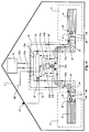
- the system according to Fig. 5 comprises a gas-fired central heating device 26, a central control unit 28 connected to the central heating device 26 by a feed pipe 30 and a return pipe 32 for a heating fluid, and eight radiators 34 connected to the central control unit 28 by feed and return pipes symbolically shown by single lines 36.
- Each radiator 34 is located in a separate room of a building, as has been explained in connection with Fig. 4, while each room contains a sensor (not shown) connected to the central control unit 28. When the sensor detects a room temperature below a predetermined value, a corresponding data signal is sent to the central control unit, which starts the central heating device 26 and provides a connection in the central control unit 28 between the central heating device 26 and the feed and return pipes 36 of the radiator 34 in the room.
- each radiator 34 in this way can be controlled individually by the central control unit 28, so that each room temperature can be regulated individually.
- an integrated pipe for the feed and return pipes 36 according to Fig. 10.
- the integrated pipe 36 of Fig. 10 all radiators 34 of Fig. 5 can be very easily installed and connected to the central control unit 28.
- the integrated pipe 36 also contains the lead 21 for interconnecting the temperature sensor in each room and the central control unit 28.
- the control unit 28 contains a suitable number of control valves for connecting one or more radiators 34 to the central heating device 26.
- the system may comprise ventilating units as described in connection with Fig. 4.
- heating fluid from the central heating device 26 can be directed by the central control unit 28 to an indirectly heated washing machine or laundry dryer 38, which basically is connected to the central control unit 28 with an integrated pipe of the type shown in Fig. 10.
- the lead 21 in the integrated pipe 36 signals a heat demand from the laundry dryer 38 to the central control unit 28, making the central control unit 28 supplying fluid heated in the central heating device 26 to the laundry dryer 38.
- the central heating device 26 is further connected by a feed pipe 40 and a return pipe 42 to an indirectly heated hot water boiler 44 for supplying hot domestic water through a pipe 46 and hot water for a hot-fill washing machine 48 and a dish-washer 50 through a pipe 52.
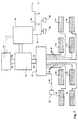
- the system shown in Fig. 7 incorporates the system of Fig. 3, and additionally has one or more high performance solar panels 54 connected to it by a feed pipe 56 and a return pipe 58 leading to the central heating device 26.
- the heat needed in the system of Fig. 7 is basically generated by the solar panel(s) 54 and supplemented by the central heating device 26 in case the heat demand exceeds the heat generated by the solar panel(s) 54.
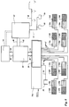
- the system according to Fig. 8 differs from the system shown in Fig. 7 in that it contains a gas-fired absorption chiller/heater 60, making it possible not only to supply convectors 34a with a heating fluid to the control unit 28, but also supplying the convectors 34a with a cooling fluid for lowering the temperature in a room.
- the convector 34a in each room is combined with a ventilating unit 34b for ventilating the room and heat recovery.
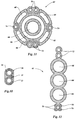
- the combined convector/ventilating units 34a, 34b are connected to the central control unit by integrated pipes of the type as shown in Figs. 11 and 12.
- the integrated pipe 62 shown in Fig. 11, which pipe may have an outer diameter of approximately 28 mm, has a feed duct 64 for feeding a heating fluid or a cooling fluid to the convector 34a, a return duct 66 for the heating or cooling fluid, four air ducts 68 for drawing air from the room and supplying it to a gas analysis unit in the central control unit 28, two electrical leads 70 for controlling actuators in the convector/ventilating unit 34a, 34b, 24 V DC power supply leads 72 for the fan(s) in the ventilating unit 34b, a room temperature sensor cable 74, and a spare sensor cable 76.
- Fig. 12 shows a different arrangement of the same type of ducts and leads as in the integrated pipe of Fig. 11, but in another spatial orientation, which makes the integrated pipe of Fig. 12 more flexible in one direction.
- central control unit 28 in the system shown is extended with a part 28a containing a central gas analysis unit and a central DC power supply.
- the system of Fig. 9 differs from the system of Fig. 8 in that it contains a cogeneration gas-fired chiller/heater/power supply and an additional photovoltaic solar panel 82 for generating the energy needed. Further, it is possible to couple the system to a district heating system 84, allowing for an abandonment of a gas supply to the system.
Landscapes
- Engineering & Computer Science (AREA)
- Chemical & Material Sciences (AREA)
- Combustion & Propulsion (AREA)
- Mechanical Engineering (AREA)
- General Engineering & Computer Science (AREA)
- Physics & Mathematics (AREA)
- Fluid Mechanics (AREA)
- Air Conditioning Control Device (AREA)
- Ventilation (AREA)
- Central Air Conditioning (AREA)
Priority Applications (3)
| Application Number | Priority Date | Filing Date | Title |
|---|---|---|---|
| AT94927856T ATE181596T1 (de) | 1994-08-08 | 1994-08-08 | Zimmerklimaanlage für ein heizungs-, kühlungs- und lüftungssystem |
| EP98204140A EP0903545A3 (en) | 1994-08-08 | 1994-08-08 | Heating, cooling and ventilating system, and room atmosphere conditioning unit for such a system |
| ES94927856T ES2133578T3 (es) | 1994-08-08 | 1994-08-08 | Unidad de acondicionamiento de aire de una habitacion para un sistema de calefaccion, enfriamiento y ventilacion. |
Applications Claiming Priority (1)
| Application Number | Priority Date | Filing Date | Title |
|---|---|---|---|
| PCT/NL1994/000185 WO1996005473A1 (en) | 1994-08-08 | 1994-08-08 | Heating, cooling and ventilating system, and room atmosphere conditioning unit for such a system |
Related Child Applications (1)
| Application Number | Title | Priority Date | Filing Date |
|---|---|---|---|
| EP98204140A Division EP0903545A3 (en) | 1994-08-08 | 1994-08-08 | Heating, cooling and ventilating system, and room atmosphere conditioning unit for such a system |
Publications (2)
| Publication Number | Publication Date |
|---|---|
| EP0783655A1 EP0783655A1 (en) | 1997-07-16 |
| EP0783655B1 true EP0783655B1 (en) | 1999-06-23 |
Family
ID=19863798
Family Applications (1)
| Application Number | Title | Priority Date | Filing Date |
|---|---|---|---|
| EP94927856A Expired - Lifetime EP0783655B1 (en) | 1994-08-08 | 1994-08-08 | Room atmosphere conditioning unit for a heating, cooling and ventilating system |
Country Status (6)
| Country | Link |
|---|---|
| EP (1) | EP0783655B1 (fi) |
| AU (1) | AU7709794A (fi) |
| DE (1) | DE69419268C5 (fi) |
| DK (1) | DK0783655T3 (fi) |
| FI (1) | FI119128B (fi) |
| WO (1) | WO1996005473A1 (fi) |
Families Citing this family (6)
| Publication number | Priority date | Publication date | Assignee | Title |
|---|---|---|---|---|
| JPH08296873A (ja) * | 1995-03-02 | 1996-11-12 | Sanden Corp | 空気調和装置 |
| GB9818305D0 (en) * | 1998-08-22 | 1998-10-14 | Nuaire Ltd | Ventilating system |
| US7730935B1 (en) | 1999-12-27 | 2010-06-08 | Carrier Corporation | Hydronic system control for heating and cooling |
| IT249515Y1 (it) * | 2000-05-23 | 2003-05-19 | Adriano Morigi | Scambiatore di calore per locali. |
| DE10201751B4 (de) * | 2002-01-18 | 2004-03-04 | Robert Bosch Gmbh | Kombiniertes Heiz-Kühlsystem |
| DE102008024839A1 (de) * | 2008-05-23 | 2009-11-26 | Boris Bergmann | Verfahren und Vorrichtung zum klimatisieren eines Raumes in einem Gebäude |
Family Cites Families (3)
| Publication number | Priority date | Publication date | Assignee | Title |
|---|---|---|---|---|
| US3969860A (en) * | 1974-07-31 | 1976-07-20 | Richard Paul Bentley | Thermal efficiency structure |
| JP2714220B2 (ja) * | 1990-03-31 | 1998-02-16 | 株式会社東芝 | 換気装置 |
| FI88650C (fi) * | 1991-04-09 | 1993-06-10 | Halton Oy | Foerfarande vid reglering av en luftkonditioneringsanlaeggning och en luftkonditioneringsanlaeggning enligt detta foerfarande |
-
1994
- 1994-08-08 WO PCT/NL1994/000185 patent/WO1996005473A1/en active IP Right Grant
- 1994-08-08 DK DK94927856T patent/DK0783655T3/da active
- 1994-08-08 EP EP94927856A patent/EP0783655B1/en not_active Expired - Lifetime
- 1994-08-08 AU AU77097/94A patent/AU7709794A/en not_active Abandoned
- 1994-08-08 DE DE69419268T patent/DE69419268C5/de not_active Expired - Lifetime
-
1997
- 1997-02-07 FI FI970546A patent/FI119128B/fi not_active IP Right Cessation
Also Published As
| Publication number | Publication date |
|---|---|
| EP0783655A1 (en) | 1997-07-16 |
| AU7709794A (en) | 1996-03-07 |
| DE69419268T2 (de) | 1999-12-09 |
| WO1996005473A1 (en) | 1996-02-22 |
| FI119128B (fi) | 2008-07-31 |
| DK0783655T3 (da) | 1999-11-22 |
| DE69419268C5 (de) | 2007-10-11 |
| FI970546A0 (fi) | 1997-02-07 |
| FI970546A (fi) | 1997-02-07 |
| DE69419268D1 (de) | 1999-07-29 |
Similar Documents
| Publication | Publication Date | Title |
|---|---|---|
| US5400607A (en) | System and method for high-efficiency air cooling and dehumidification | |
| US20080173035A1 (en) | Split system dehumidifier | |
| CN113790479B (zh) | 一种具有除湿及热水功能的热泵空调 | |
| EP0783655B1 (en) | Room atmosphere conditioning unit for a heating, cooling and ventilating system | |
| JPH1163561A (ja) | 冷媒自然循環式熱交換システム | |
| US5318099A (en) | Method and apparatus for emulating a perimeter induction unit air conditioning system | |
| EP0903545A2 (en) | Heating, cooling and ventilating system, and room atmosphere conditioning unit for such a system | |
| CA1213255A (en) | Air heating and ventilation system | |
| CN216346649U (zh) | 新风设备及多联机空调系统 | |
| EP0672231B1 (en) | Method and arrangement for air-conditioning and heating room space | |
| JPH04309731A (ja) | 動物飼育室の空調制御システム | |
| JP2004003866A (ja) | 換気空調装置 | |
| JPH06193947A (ja) | アンダーフロアー空調システム | |
| CN109059141A (zh) | 地面调温与新风温度调节除湿联动的室内气候调节系统 | |
| CN201599880U (zh) | 一种空调机 | |
| Bhatia | Design Options for HVAC Distribution Systems | |
| GB2220475A (en) | Ventilating systems | |
| US3459257A (en) | Room cooling system | |
| CN216814447U (zh) | 一种恒温恒湿恒氧安装系统 | |
| CN216897628U (zh) | 一种新风式五恒科技住宅节能系统 | |
| CN217737494U (zh) | 一种可调温多冷源新风除湿机 | |
| US3842903A (en) | Novel heating,ventilating and air-conditioning system | |
| US20240159424A1 (en) | Heating, Ventilation, and Air Conditioning System and Method | |
| JPH05196258A (ja) | 空気調和設備 | |
| JP3069517B2 (ja) | 換気システムの加温ユニット |
Legal Events
| Date | Code | Title | Description |
|---|---|---|---|
| PUAI | Public reference made under article 153(3) epc to a published international application that has entered the european phase |
Free format text: ORIGINAL CODE: 0009012 |
|
| 17P | Request for examination filed |
Effective date: 19970206 |
|
| AK | Designated contracting states |
Kind code of ref document: A1 Designated state(s): AT BE CH DE DK ES FR GB GR IE IT LI LU MC NL PT SE |
|
| 17Q | First examination report despatched |
Effective date: 19970814 |
|
| GRAG | Despatch of communication of intention to grant |
Free format text: ORIGINAL CODE: EPIDOS AGRA |
|
| GRAG | Despatch of communication of intention to grant |
Free format text: ORIGINAL CODE: EPIDOS AGRA |
|
| GRAH | Despatch of communication of intention to grant a patent |
Free format text: ORIGINAL CODE: EPIDOS IGRA |
|
| GRAH | Despatch of communication of intention to grant a patent |
Free format text: ORIGINAL CODE: EPIDOS IGRA |
|
| GRAA | (expected) grant |
Free format text: ORIGINAL CODE: 0009210 |
|
| AK | Designated contracting states |
Kind code of ref document: B1 Designated state(s): AT BE CH DE DK ES FR GB GR IE IT LI LU MC NL PT SE |
|
| PG25 | Lapsed in a contracting state [announced via postgrant information from national office to epo] |
Ref country code: GR Free format text: LAPSE BECAUSE OF NON-PAYMENT OF DUE FEES Effective date: 19990623 |
|
| REF | Corresponds to: |
Ref document number: 181596 Country of ref document: AT Date of ref document: 19990715 Kind code of ref document: T |
|
| RIN1 | Information on inventor provided before grant (corrected) |
Inventor name: VAN HOLSTEIJN, ROBERTUS, CORNELIS, ADRIANUS Inventor name: KEMNA, RENE, BERTINUS, JOANNES |
|
| REG | Reference to a national code |
Ref country code: CH Ref legal event code: NV Representative=s name: TROESCH SCHEIDEGGER WERNER AG Ref country code: CH Ref legal event code: EP |
|
| REF | Corresponds to: |
Ref document number: 69419268 Country of ref document: DE Date of ref document: 19990729 |
|
| ITF | It: translation for a ep patent filed |
Owner name: UFFICIO TECNICO ING. A. MANNUCCI |
|
| REG | Reference to a national code |
Ref country code: IE Ref legal event code: FG4D |
|
| REG | Reference to a national code |
Ref country code: ES Ref legal event code: FG2A Ref document number: 2133578 Country of ref document: ES Kind code of ref document: T3 |
|
| PG25 | Lapsed in a contracting state [announced via postgrant information from national office to epo] |
Ref country code: PT Free format text: LAPSE BECAUSE OF FAILURE TO SUBMIT A TRANSLATION OF THE DESCRIPTION OR TO PAY THE FEE WITHIN THE PRESCRIBED TIME-LIMIT Effective date: 19990923 |
|
| ET | Fr: translation filed | ||
| REG | Reference to a national code |
Ref country code: DK Ref legal event code: T3 |
|
| PG25 | Lapsed in a contracting state [announced via postgrant information from national office to epo] |
Ref country code: MC Free format text: LAPSE BECAUSE OF NON-PAYMENT OF DUE FEES Effective date: 20000229 |
|
| PLBE | No opposition filed within time limit |
Free format text: ORIGINAL CODE: 0009261 |
|
| STAA | Information on the status of an ep patent application or granted ep patent |
Free format text: STATUS: NO OPPOSITION FILED WITHIN TIME LIMIT |
|
| 26N | No opposition filed | ||
| REG | Reference to a national code |
Ref country code: GB Ref legal event code: IF02 |
|
| NLR4 | Nl: receipt of corrected translation in the netherlands language at the initiative of the proprietor of the patent | ||
| PGFP | Annual fee paid to national office [announced via postgrant information from national office to epo] |
Ref country code: IE Payment date: 20110722 Year of fee payment: 18 |
|
| PGFP | Annual fee paid to national office [announced via postgrant information from national office to epo] |
Ref country code: AT Payment date: 20110829 Year of fee payment: 18 Ref country code: SE Payment date: 20110825 Year of fee payment: 18 |
|
| PGFP | Annual fee paid to national office [announced via postgrant information from national office to epo] |
Ref country code: NL Payment date: 20110901 Year of fee payment: 18 Ref country code: IT Payment date: 20110829 Year of fee payment: 18 |
|
| PGFP | Annual fee paid to national office [announced via postgrant information from national office to epo] |
Ref country code: ES Payment date: 20110829 Year of fee payment: 18 |
|
| REG | Reference to a national code |
Ref country code: DE Ref legal event code: R097 Ref document number: 69419268 Country of ref document: DE |
|
| REG | Reference to a national code |
Ref country code: NL Ref legal event code: V1 Effective date: 20130301 |
|
| REG | Reference to a national code |
Ref country code: SE Ref legal event code: EUG |
|
| REG | Reference to a national code |
Ref country code: AT Ref legal event code: MM01 Ref document number: 181596 Country of ref document: AT Kind code of ref document: T Effective date: 20120808 |
|
| PG25 | Lapsed in a contracting state [announced via postgrant information from national office to epo] |
Ref country code: SE Free format text: LAPSE BECAUSE OF NON-PAYMENT OF DUE FEES Effective date: 20120809 Ref country code: NL Free format text: LAPSE BECAUSE OF NON-PAYMENT OF DUE FEES Effective date: 20130301 |
|
| REG | Reference to a national code |
Ref country code: DE Ref legal event code: R040 Ref document number: 69419268 Country of ref document: DE Effective date: 20121006 |
|
| REG | Reference to a national code |
Ref country code: IE Ref legal event code: MM4A |
|
| PG25 | Lapsed in a contracting state [announced via postgrant information from national office to epo] |
Ref country code: IT Free format text: LAPSE BECAUSE OF NON-PAYMENT OF DUE FEES Effective date: 20120808 |
|
| PG25 | Lapsed in a contracting state [announced via postgrant information from national office to epo] |
Ref country code: AT Free format text: LAPSE BECAUSE OF NON-PAYMENT OF DUE FEES Effective date: 20120808 |
|
| PG25 | Lapsed in a contracting state [announced via postgrant information from national office to epo] |
Ref country code: IE Free format text: LAPSE BECAUSE OF NON-PAYMENT OF DUE FEES Effective date: 20120808 |
|
| PGFP | Annual fee paid to national office [announced via postgrant information from national office to epo] |
Ref country code: LU Payment date: 20130828 Year of fee payment: 20 |
|
| REG | Reference to a national code |
Ref country code: ES Ref legal event code: FD2A Effective date: 20131018 |
|
| PG25 | Lapsed in a contracting state [announced via postgrant information from national office to epo] |
Ref country code: ES Free format text: LAPSE BECAUSE OF NON-PAYMENT OF DUE FEES Effective date: 20120809 |
|
| PGFP | Annual fee paid to national office [announced via postgrant information from national office to epo] |
Ref country code: CH Payment date: 20130827 Year of fee payment: 20 Ref country code: DE Payment date: 20130827 Year of fee payment: 20 Ref country code: DK Payment date: 20130829 Year of fee payment: 20 |
|
| PGFP | Annual fee paid to national office [announced via postgrant information from national office to epo] |
Ref country code: FR Payment date: 20130827 Year of fee payment: 20 Ref country code: GB Payment date: 20130726 Year of fee payment: 20 |
|
| PGFP | Annual fee paid to national office [announced via postgrant information from national office to epo] |
Ref country code: BE Payment date: 20130827 Year of fee payment: 20 |
|
| REG | Reference to a national code |
Ref country code: DE Ref legal event code: R071 Ref document number: 69419268 Country of ref document: DE |
|
| REG | Reference to a national code |
Ref country code: DE Ref legal event code: R071 Ref document number: 69419268 Country of ref document: DE |
|
| REG | Reference to a national code |
Ref country code: DK Ref legal event code: EUP Effective date: 20140808 |
|
| REG | Reference to a national code |
Ref country code: CH Ref legal event code: PL |
|
| REG | Reference to a national code |
Ref country code: GB Ref legal event code: PE20 Expiry date: 20140807 |
|
| BE20 | Be: patent expired |
Owner name: *VAN HOLSTEIJN & KEMNA SPECIAL PRODUCTS B.V. Effective date: 20140808 |
|
| PG25 | Lapsed in a contracting state [announced via postgrant information from national office to epo] |
Ref country code: DE Free format text: LAPSE BECAUSE OF EXPIRATION OF PROTECTION Effective date: 20140809 |
|
| PG25 | Lapsed in a contracting state [announced via postgrant information from national office to epo] |
Ref country code: GB Free format text: LAPSE BECAUSE OF EXPIRATION OF PROTECTION Effective date: 20140807 |