EP0783361B1 - Filtering device with demountable filter cartridge - Google Patents
Filtering device with demountable filter cartridge Download PDFInfo
- Publication number
- EP0783361B1 EP0783361B1 EP95932107A EP95932107A EP0783361B1 EP 0783361 B1 EP0783361 B1 EP 0783361B1 EP 95932107 A EP95932107 A EP 95932107A EP 95932107 A EP95932107 A EP 95932107A EP 0783361 B1 EP0783361 B1 EP 0783361B1
- Authority
- EP
- European Patent Office
- Prior art keywords
- casing
- filter
- fluid
- filter cartridge
- filter element
- Prior art date
- Legal status (The legal status is an assumption and is not a legal conclusion. Google has not performed a legal analysis and makes no representation as to the accuracy of the status listed.)
- Expired - Lifetime
Links
- 238000001914 filtration Methods 0.000 title description 2
- 239000012530 fluid Substances 0.000 claims abstract description 30
- 230000000717 retained effect Effects 0.000 claims abstract description 6
- 230000002265 prevention Effects 0.000 claims description 2
- 239000003921 oil Substances 0.000 description 20
- 238000004140 cleaning Methods 0.000 description 3
- 238000010276 construction Methods 0.000 description 3
- 238000002485 combustion reaction Methods 0.000 description 2
- 230000007613 environmental effect Effects 0.000 description 2
- 238000005461 lubrication Methods 0.000 description 2
- 239000010705 motor oil Substances 0.000 description 2
- 230000000737 periodic effect Effects 0.000 description 2
- 239000000853 adhesive Substances 0.000 description 1
- 230000001070 adhesive effect Effects 0.000 description 1
- 230000008878 coupling Effects 0.000 description 1
- 238000010168 coupling process Methods 0.000 description 1
- 238000005859 coupling reaction Methods 0.000 description 1
- 239000003599 detergent Substances 0.000 description 1
- 230000003670 easy-to-clean Effects 0.000 description 1
- 238000007689 inspection Methods 0.000 description 1
- 238000009434 installation Methods 0.000 description 1
- 238000002955 isolation Methods 0.000 description 1
- 239000000463 material Substances 0.000 description 1
- 230000013011 mating Effects 0.000 description 1
- 238000000034 method Methods 0.000 description 1
- 239000013618 particulate matter Substances 0.000 description 1
- 239000004033 plastic Substances 0.000 description 1
- 229920003023 plastic Polymers 0.000 description 1
- 238000003825 pressing Methods 0.000 description 1
- 238000007789 sealing Methods 0.000 description 1
- 239000013585 weight reducing agent Substances 0.000 description 1
Images

Classifications
-
- B—PERFORMING OPERATIONS; TRANSPORTING
- B01—PHYSICAL OR CHEMICAL PROCESSES OR APPARATUS IN GENERAL
- B01D—SEPARATION
- B01D35/00—Filtering devices having features not specifically covered by groups B01D24/00 - B01D33/00, or for applications not specifically covered by groups B01D24/00 - B01D33/00; Auxiliary devices for filtration; Filter housing constructions
- B01D35/30—Filter housing constructions
- B01D35/31—Filter housing constructions including arrangements for environmental protection, e.g. pressure resisting features
-
- B—PERFORMING OPERATIONS; TRANSPORTING
- B01—PHYSICAL OR CHEMICAL PROCESSES OR APPARATUS IN GENERAL
- B01D—SEPARATION
- B01D29/00—Filters with filtering elements stationary during filtration, e.g. pressure or suction filters, not covered by groups B01D24/00 - B01D27/00; Filtering elements therefor
- B01D29/11—Filters with filtering elements stationary during filtration, e.g. pressure or suction filters, not covered by groups B01D24/00 - B01D27/00; Filtering elements therefor with bag, cage, hose, tube, sleeve or like filtering elements
- B01D29/114—Filters with filtering elements stationary during filtration, e.g. pressure or suction filters, not covered by groups B01D24/00 - B01D27/00; Filtering elements therefor with bag, cage, hose, tube, sleeve or like filtering elements arranged for inward flow filtration
-
- B—PERFORMING OPERATIONS; TRANSPORTING
- B01—PHYSICAL OR CHEMICAL PROCESSES OR APPARATUS IN GENERAL
- B01D—SEPARATION
- B01D29/00—Filters with filtering elements stationary during filtration, e.g. pressure or suction filters, not covered by groups B01D24/00 - B01D27/00; Filtering elements therefor
- B01D29/96—Filters with filtering elements stationary during filtration, e.g. pressure or suction filters, not covered by groups B01D24/00 - B01D27/00; Filtering elements therefor in which the filtering elements are moved between filtering operations; Particular measures for removing or replacing the filtering elements; Transport systems for filters
-
- B—PERFORMING OPERATIONS; TRANSPORTING
- B01—PHYSICAL OR CHEMICAL PROCESSES OR APPARATUS IN GENERAL
- B01D—SEPARATION
- B01D2201/00—Details relating to filtering apparatus
- B01D2201/40—Special measures for connecting different parts of the filter
- B01D2201/4015—Bayonet connecting means
-
- Y—GENERAL TAGGING OF NEW TECHNOLOGICAL DEVELOPMENTS; GENERAL TAGGING OF CROSS-SECTIONAL TECHNOLOGIES SPANNING OVER SEVERAL SECTIONS OF THE IPC; TECHNICAL SUBJECTS COVERED BY FORMER USPC CROSS-REFERENCE ART COLLECTIONS [XRACs] AND DIGESTS
- Y10—TECHNICAL SUBJECTS COVERED BY FORMER USPC
- Y10S—TECHNICAL SUBJECTS COVERED BY FORMER USPC CROSS-REFERENCE ART COLLECTIONS [XRACs] AND DIGESTS
- Y10S210/00—Liquid purification or separation
- Y10S210/17—Twist-on
Abstract
Description
- This invention relates to fluid filtration and in particular to a reusable spin-on fluid filter cartridge including a demountable filter element.
- Traditional fluid filter cartridges for fluids such as engine oil have been almost entirely of the disposable kind in which a pleated paper filter element is employed. Such filter cartridges are generally used in a full and partial flow modes, all or part of the engine oil being passed through the filter of the filter element prior to re-circulation through the engine bearings and other moving parts requiring lubrication. Inevitably, the filter becomes progressively occluded by debris from the engine and from the combustion process. Equally inevitably, the filter cartridge must be replaced periodically and to facilitate this, the well-known spin-on, spin-off construction is now widely used. The used filter cartridge is simply thrown away and replaced by a new one at each oil change. However, such disposal creates environmental problems due to the difficulty of removing oil from the spent filter cartridge. To minimize environmental problems either a reusable filter cartridge with a cleanable filter element, or a much longer period between oil changes, or both, would be desirable.
- It has been proposed that oil changes should be at greater intervals, but this imposes considerably greater demands on the oil filter and in particular on its ability to hold debris without at the same time developing an unacceptably high back pressure or restriction to fluid flow. One way of addressing this problem is to use a centrifugal cleaner of the kind in which oil under pressure is admitted to a rotor from which it escapes through nozzles which cause the rotor to spin about its axis. The centrifuge thus formed serves to remove particulate matter very efficiently, it only being necessary to clean out or even replace the rotor after very high mileages, in the case of a vehicle, or after a very extended running period, in the case of a stationary engine.
- However, as a practical matter, it is not desirable to run a centrifugal cleaner of this self-powered kind in a full flow environment. It is usual to pass about 10 percent of the total flow through the centrifugal cleaner and the rest of the flow through a filter, either of the conventional paper element kind or through at least a relatively simple wire strainer which can be dismantled for periodic cleaning.
- The present invention is concerned with a full flow filter of this latter kind. It is an object of the present invention to provide a reusable filter cartridge of the spin-on type which is relatively easy to clean or to replace and with a minimum of components, including oil seals.
- In the preferred embodiment, the reusable filter cartridge has a single external oil seal for isolation of both clean and dirty oil from the environment.
- According to the present invention, a fluid filter cartridge comprises a generally tubular casing closed at one end and having at the opposite, open end thereof, an annular member defining a filter element receiving aperture and provided with an elastomeric seal for prevention of leakage of fluid to the environment, said seal extending circumferentially of the casing and projecting axially away from the casing; a filter element including a base ring provided with means whereby it can be attached to a supply of fluid to be filtered together with at least one port whereby filtered fluid can flow from the element; said filter element further comprising a generally tubular filter extending within said casing from said base ring, an end closure therefor, together with connection means defined by the annular member radially inwardly of said casing and by the base ring radially outwardly of said filter element, whereby the latter is removably retained in the casing after rotation of the filter element about its axis relative to the casing of said filter element whereby the latter is removably retained in the casing after rotation of the base ring about its axis relative to the axis of the casing. Said connection means is preferably a bayonet connection.
- It will be appreciated that a bayonet connection between the filter element and the casing may be implemented in a number of ways. However, in the interest of simplicity, it is convenient to provide bayonet connection means at or adjacent one end of the casing, with the open end being particularly preferred. According to a particularly preferred aspect of the invention, a fluid filter cartridge comprises a generally tubular casing closed at one end and having at the opposite, open end thereof, an annular member defining a filter element receiving aperture and provided with a single external seal extending circumferentially of the casing and projecting generally axially away from the casing, said annular member including at least two inwardly directed projections equally spaced about the circumference of the casing and projecting into said aperture, a filter element including a base ring provided with means whereby it can be attached to a supply of fluid to be filtered together with at least one port whereby filtered fluid can flow from the cartridge, a generally tubular filter which is preferably affixed to and extending from said base ring to an end closure therefor,said base ring being provided with slots through which said projections may freely pass together with recesses into which said projections are received after passage through said slots and after rotation of the filter element about its axis relative to the axis of the casing, whereby the filter element is removably retained in said casing.
- Advantageously, spring means are provided to promote engagement of the bayonet connection after installation of the filter element. Conveniently the spring means take the form of a resilient member such as a spring interposed between the end closure of the filter element and the end closure for the casing. The spring may be attached to the end closure of the filter element or it may be attached to the end of the casing so as to project towards and engage the free end of the filter element.
- Preferably there are three equally spaced inwardly directed projections and three corresponding recesses to receive them.
- The filter element preferably incorporates a cleanable filter which is a screen of wire mesh, although other materials may be useable including conventional filter media of the disposable kind.
- A particularly important aspect of the invention is its relative simplicity, because it has minimal parts and only one external seal which is located radially outwardly from the fluid inlet and outlet ports and the coupling between the annular member and the base ring of the filter element. According to a further aspect of the invention, the filter cartridge of the present invention is used in conjunction with a centrifugal cleaner, either with both mounted to a common supporting structure or if circumstances require it, installed separately. In this case, it is preferred that only about 10 percent of the fluid flow shall pass through the centrifugal cleaner and the remainder through the fluid filter of the present invention. Such an arrangement is especially useful for internal combustion engine applications.
- In order that the invention be better understood, a preferred embodiment of it will now be described by way of example with reference to the accompanying drawings in which:
- Figure 1 is a cross-sectional side view of a reusable filter cartridge with a demountable filter element in accordance with this invention; and
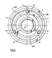
- Figure 2 is an end view of parts of the filter cartridge of Figure 1, taken in the direction of arrow "X" of the latter.
-
- Like parts in all Figures bear like reference numerals, for ease of identification.
- Referring firstly to Figure 1, a generally
tubular casing 1 is open at one end, 2, and closed at the opposite end 3. The open end may be flared at 4 to provide a smaller and more economical casing, and the enlarged diameter portion receives anannular ring 5, which is best seen in plan view of Figure 2. An annular axially directed recess in the outwardly facing surface of thering 5 holds anoil seal 6 which projects axially of the surface of the ring, away from the casing. The oil seal prevents leakage of oil to atmosphere. Thering 5 is welded to the casing at 7 and has three equally spaced inwardly projectingpins 8, one only of which is seen in Figure 1. The pins are secured by adhesive or are press fit into apertures or may be cast as integral parts ofring 5. Inside the casing there is provided a cleanable filter element comprising abase ring 10 which is a push fit into thering 5 and which carries the filter medium which preferably comprises tubular wiremesh filter screen 11. The filter screen includes a pair of stiffening/support rings 12 and has at its opposite end aclosure plate 14 to which is bondedspring 15. The closure plate itself is bonded to the otherwise open end of the filter screen. Alternately, thefilter screen 11 may be constituted by a tubular element of paper, foamed plastics, or any other permeable filter medium of the kind commonly used in the art. It may be integral with, or demountable from the base ring. - Referring now to Figure 2 in particular, the
base ring 10 is provided with a central boss which defines the margin of an internally screw threadedaperture 20. This aperture serves both as an oil outlet and as a means of mounting the filter cartridge to associated equipment by the conventional spin-on route, the filter cartridge being screwed down onto a mating boss (not shown) until theseal 6 seats firmly on to the hardware to prevent leakage.Base ring 10 is also provided with threeslots 25 through which thepins 8 can freely enter during assembly, theslots 25 further serving as oil ways. Intermediate theslots 25 there are blind slots orrecesses 26 which although shown in detail in Figure 2, are not open to the inside of the casing in the direction of the closed end thereof. As a result, the filter cartridge can only be installed by relative rotation of the filter element and the casing until thepins 8 are lined up with theslots 25, pressing thebase ring 10 into the casing against thespring 15, and then rotating the base ring and casing relative to one another until the pins andrecesses 26 are aligned. The pins can then enter the latter to seat against the underlying portion ofbase ring 10 and assembly is thus completed. Removal of the base ring and filter medium for inspection and/or cleaning is the opposite of assembly and is equally straightforward. Additionalbase ring recesses 28 may be provided, for weight reduction purposes, as desired. - Use of the assembled filter cartridge is conventional. The screw-threaded
aperture 20 provides means whereby the filter cartridge may be mounted on or adjacent an engine, for example by screwing it down onto a projecting oilway which is correspondingly externally threaded, until theoil seal 6 seats against associated hardware to form a seal. The threads ofapertures 20 act as an internal seal to isolate dirty oil from clean oil, although as an added precaution, one or more sealing rings may be provided within the aperture. The only seal in Figures 1 and 2 isseal 6 which isolates oil from the atmosphere. It can be seen in Figure 1 thatseal 6 is located radially outwardly of all potential leakage paths. - The invention can provide for flow in either direction, but without the complexity of prior art devices. It will be appreciated that the embodiment of Figure 1 incorporates the provision of a single external seal in a reusable spin-on filter cartridge incorporating a demountable, cleanable and reusable filter element and that many other variants are possible without departing from the invention.
- It will be appreciated that the demountable filter element of the reusable filter cartridge just described is readily cleanable in that the filter is of wire mesh. However, the same construction can be equally useful for disposable filter media such as paper and the like, as mentioned earlier. Also, as mentioned earlier, the actual filter element may be demountable from the
base ring 10. It will also be appreciated that the direction of flow of the oil is not critical; the same construction principles can be used for both inside-to-out, and outside-to-in oil flows. In some circumstances, periodic cleaning of the filter screen may be accomplished by reverse flow techniques, using a detergent-containing medium. - Where appropriate, a pressure relief valve may be incorporated into the assembly so that on clogging of the filter element for any reason, the flow can bypass the filter element. Similarly, a non-return valve may be included to keep the filter cartridge full during shut downs so that there is no delay of engine lubrication on start up and further to prevent reverse flow in normal use, thereby preventing detritus from being flushed back into an associated engine. Such relief and one-way valve systems are of course well-known in the art.
Claims (10)
- A fluid filter cartridge comprising a generally tubular casing (1) closed at one end (3) and having at the opposite, open end thereof (2), an annular member (5) defining a filter element receiving aperture and provided with an elastomeric seal (6) for prevention of leakage of fluid to the environment, said seal extending circumferentially of the casing and projecting axially away from the casing;a filter element including a base ring (10) provided with means (20) whereby it can be attached to a supply of fluid to be filtered together with at least one port whereby filtered fluid can flow from the element;said filter element further comprising a generally tubular filter (11) extending within said casing from said base ring, an end closure therefor (14),together with connection means (8, 26) defined by the annular member radially inwardly of said casing and by the base ring radially outwardly of said filter element, whereby the latter is removably retained in the casing after rotation of the filter element about its axis relative to the casing.
- A fluid filter cartridge as claimed in claim 1 characterised in that said tubular filter comprises a tubular filter screen (11).
- A fluid filter cartridge of claim 2, characterised in that the tubular filter screen is constituted by a cleanable wire mesh.
- A fluid filter cartridge as claimed in any one of claims 1 to 3 characterised in that said connection means is constituted by bayonet connection means (8, 26, 15).
- A fluid filter cartridge as claimed in claim 4 characterised in that the bayonet connection means comprises at least two projections (8), equally spaced about the annular member (5) in a circumferential direction and projecting into said aperture, and in the base ring (10), slots (25) through which said projections may freely pass and recesses (26) into which said projections can be received after passage through said slots and after rotation of the filter cartridge about its axis relative to the casing, whereby the filter element is removably retained in said casing.
- A fluid filter cartridge as claimed in claim 5 characterised by spring means (15) adapted to urge the projections (8) and recesses (26) to engage.
- A fluid filter cartridge as claimed in claim 6 characterised in that said spring means is constituted by a resilient member (15) interposed between the end closure of the filter element (14) and the end closure for the casing (3).
- A fluid filter cartridge as claimed in claim 6, characterised in that said resilient member comprises a spring attached to the end closure of the filter element (14) so as to project therefrom.
- A fluid filter cartridge as claimed in any one of claims 5 to 8 characterised in that said slots (25) serve as inlet passages for fluid to be filtered.
- A fluid filter cartridge as claimed in any one of claims 4 to 9 characterised in that said bayonet connection means is constituted by three equally spaced inwardly directed projections (8) and three corresponding recesses (26) to receive said projections.
Applications Claiming Priority (5)
| Application Number | Priority Date | Filing Date | Title |
|---|---|---|---|
| US311936 | 1989-02-15 | ||
| US31193694A | 1994-09-26 | 1994-09-26 | |
| US08/515,715 US5643448A (en) | 1994-09-26 | 1995-08-16 | Spin-on filter assembly incorporating a re-usable tubular filter screen |
| PCT/GB1995/002263 WO1996009875A1 (en) | 1994-09-26 | 1995-09-25 | Filtering device with demountable filter cartridge |
| US515715 | 2000-02-28 |
Publications (2)
| Publication Number | Publication Date |
|---|---|
| EP0783361A1 EP0783361A1 (en) | 1997-07-16 |
| EP0783361B1 true EP0783361B1 (en) | 2000-03-08 |
Family
ID=26978143
Family Applications (1)
| Application Number | Title | Priority Date | Filing Date |
|---|---|---|---|
| EP95932107A Expired - Lifetime EP0783361B1 (en) | 1994-09-26 | 1995-09-25 | Filtering device with demountable filter cartridge |
Country Status (7)
| Country | Link |
|---|---|
| US (1) | US5643448A (en) |
| EP (1) | EP0783361B1 (en) |
| JP (1) | JPH10506325A (en) |
| AT (1) | ATE190237T1 (en) |
| DE (1) | DE69515495T2 (en) |
| ES (1) | ES2145296T3 (en) |
| WO (1) | WO1996009875A1 (en) |
Cited By (2)
| Publication number | Priority date | Publication date | Assignee | Title |
|---|---|---|---|---|
| EP2092970A1 (en) * | 2008-02-08 | 2009-08-26 | ARGO-HYTOS GmbH | Filter device for filtering a liquid and filter element for such a filter device |
| US10010816B2 (en) | 2014-03-03 | 2018-07-03 | Fsp Fluid Systems Partners Holding Ag | Filter device for filtering a hydraulic fluid |
Families Citing this family (29)
| Publication number | Priority date | Publication date | Assignee | Title |
|---|---|---|---|---|
| US5567323A (en) * | 1995-04-06 | 1996-10-22 | Harrison-Pipkin, L.L.C. | Intake filter for a paint sprayer |
| US6006924A (en) * | 1997-05-14 | 1999-12-28 | Pti Technologies, Inc. | Multi-media filtration system with reusable and demountable filter cartridge |
| US6024229A (en) * | 1998-02-27 | 2000-02-15 | Ayers; William R. | Reusable filter assembly |
| ES2249305T3 (en) | 1999-10-12 | 2006-04-01 | Roger P. Reid | RECYCLABLE AND PRESSURE PRESSURE FILTER CARTRIDGE. |
| US7166215B2 (en) * | 1999-10-12 | 2007-01-23 | Reid Roger P | Pressure vessel and recyclable filter cartridge |
| US6319417B1 (en) | 2000-03-21 | 2001-11-20 | Scott A. Rodibaugh | Self-cleaning filter system |
| WO2002078816A1 (en) * | 2001-04-02 | 2002-10-10 | Donaldson Company, Inc. | Bowl-cartridge filter having interlock mechanism and methods |
| DE10142774A1 (en) * | 2001-08-31 | 2003-03-27 | Hydac Filtertechnik Gmbh | filter means |
| US20060021925A1 (en) * | 2004-08-02 | 2006-02-02 | Jack Stifelman | Re-usable structure which attaches to the same filter head as originally intended to receive a throw-away spin-on |
| US20070095744A1 (en) * | 2005-11-01 | 2007-05-03 | Bagci Ismail C | Fluid filter with open-end flow, replaceable cartridge |
| US8293103B2 (en) | 2005-12-08 | 2012-10-23 | Donaldson Company, Inc. | Spin-on filter assembly and methods |
| DE102007018632B4 (en) * | 2006-04-25 | 2009-07-09 | Georgij Anatolijovych Koltunov | Method for fixing a cover in the housing of an oil filter |
| CN100560176C (en) * | 2008-03-17 | 2009-11-18 | 周育强 | A kind of method and device that connects filter with middleware |
| US8187458B2 (en) | 2009-03-18 | 2012-05-29 | Lifetime Oil Filter, Inc. | Oil filter |
| DE102009054084A1 (en) | 2009-11-20 | 2011-05-26 | Eoil Automotive & Technologies Gmbh | Changeable cartridge filter has housing and filter element provided in housing, where filter element is flow throughable by hydraulic oil or fuel |
| US9194265B2 (en) | 2010-01-27 | 2015-11-24 | Cummins Filtration Ip, Inc. | Rotating separator with housing preventing separated liquid carryover |
| US8893689B2 (en) | 2010-01-27 | 2014-11-25 | Cummins Filtration Ip, Inc. | Crankcase ventilation self-cleaning coalescer with intermittent rotation |
| US8974567B2 (en) | 2010-01-27 | 2015-03-10 | Cummins Filtration Ip Inc. | Rotating coalescer with keyed drive |
| US8807097B2 (en) | 2010-01-27 | 2014-08-19 | Cummins Filtration Ip Inc. | Closed crankcase ventilation system |
| US8940068B2 (en) | 2010-01-27 | 2015-01-27 | Cummins Filtration Ip Inc. | Magnetically driven rotating separator |
| WO2012040382A2 (en) | 2010-09-21 | 2012-03-29 | Lifetime Oil Filter, Inc. | Oil filter |
| IN2014CN03311A (en) | 2011-11-04 | 2015-07-03 | Cummins Filtration Ip Inc | |
| DE202012104683U1 (en) * | 2012-12-03 | 2014-03-05 | Wild Dairy Ingredients Gmbh | Protection device for an internal filter |
| DE102013019807B4 (en) * | 2013-11-26 | 2023-07-20 | Hydac Filtertechnik Gmbh | Filter device and filter element |
| CN107530597A (en) * | 2015-04-30 | 2018-01-02 | 未来儿株式会社 | Filter |
| TR201707827A2 (en) * | 2017-05-29 | 2017-09-21 | Mikropor Makina Sanayi Ve Ticaret Anonim Sirketi | OIL SEPARATOR USED IN SYSTEMS REQUIRING OIL SEPARATION AND FILTRATION |
| EP3643386B1 (en) | 2018-10-23 | 2024-02-21 | Volvo Car Corporation | Improved oil filter |
| PL238978B1 (en) * | 2019-04-10 | 2021-10-25 | Kosinski Robert | Tank lid |
| CN116395717B (en) * | 2023-06-08 | 2023-10-03 | 内蒙古星汉新材料有限公司 | Method for improving morphology of potassium fluoride |
Family Cites Families (17)
| Publication number | Priority date | Publication date | Assignee | Title |
|---|---|---|---|---|
| US2031589A (en) * | 1932-07-11 | 1936-02-25 | Michiana Products Corp | Filter |
| US2097828A (en) * | 1936-10-15 | 1937-11-02 | Jesse A Baldwin | Oil filter |
| US2471069A (en) * | 1944-03-28 | 1949-05-24 | Tecalemit Ltd | Oil or liquid filter |
| GB982548A (en) * | 1961-03-01 | 1965-02-03 | Knecht Alfred | Improvements in or relating to oil filters |
| US3260367A (en) * | 1963-12-05 | 1966-07-12 | Champion Lab Inc | Oil filter with removable housing |
| US3640390A (en) * | 1968-05-13 | 1972-02-08 | Torite Enterprises Inc | Replaceable cartridge filter housing |
| US3502221A (en) * | 1968-05-14 | 1970-03-24 | Spraying Systems Co | Filter unit for sprayers |
| US4052307A (en) * | 1976-07-08 | 1977-10-04 | Wix Corporation | Universal filter mounting attachment |
| SU1174057A1 (en) * | 1983-10-12 | 1985-08-23 | Уральский Автомобильный Завод Им.60-Летия Ссср | Filter for purifying liquid |
| US4992166A (en) * | 1988-06-13 | 1991-02-12 | Facet Enterprises, Inc. | Plastic fluid filter and method for manufacturing same |
| SU1643051A1 (en) * | 1988-10-18 | 1991-04-23 | B.C. Русаков и Ю.В. Русаков | Oil filter |
| US4997556A (en) * | 1988-12-26 | 1991-03-05 | Mitsubishi Oil Co., Ltd. | Oil filter I |
| US5080787A (en) * | 1989-11-02 | 1992-01-14 | Fleetguard, Inc. | High-pressure filter assembly, method and apparatus for forming high-pressure filters |
| US5066391A (en) * | 1990-08-22 | 1991-11-19 | Faria Manuel S | Reusable liquid filter assembly |
| US5230795A (en) * | 1991-12-12 | 1993-07-27 | Yang Wen Chen | Quick release oil filter |
| US5336406A (en) * | 1993-01-26 | 1994-08-09 | Elkay Manufacturing Company | Replaceable filter cartridge and head assembly with safety shut-off valve |
| US5342519A (en) * | 1993-07-30 | 1994-08-30 | Donaldson Company, Inc. | Fluid filter cartridge with replaceable filter element |
-
1995
- 1995-08-16 US US08/515,715 patent/US5643448A/en not_active Expired - Fee Related
- 1995-09-25 JP JP8511492A patent/JPH10506325A/en active Pending
- 1995-09-25 DE DE69515495T patent/DE69515495T2/en not_active Expired - Lifetime
- 1995-09-25 AT AT95932107T patent/ATE190237T1/en not_active IP Right Cessation
- 1995-09-25 WO PCT/GB1995/002263 patent/WO1996009875A1/en active IP Right Grant
- 1995-09-25 ES ES95932107T patent/ES2145296T3/en not_active Expired - Lifetime
- 1995-09-25 EP EP95932107A patent/EP0783361B1/en not_active Expired - Lifetime
Cited By (2)
| Publication number | Priority date | Publication date | Assignee | Title |
|---|---|---|---|---|
| EP2092970A1 (en) * | 2008-02-08 | 2009-08-26 | ARGO-HYTOS GmbH | Filter device for filtering a liquid and filter element for such a filter device |
| US10010816B2 (en) | 2014-03-03 | 2018-07-03 | Fsp Fluid Systems Partners Holding Ag | Filter device for filtering a hydraulic fluid |
Also Published As
| Publication number | Publication date |
|---|---|
| EP0783361A1 (en) | 1997-07-16 |
| ATE190237T1 (en) | 2000-03-15 |
| US5643448A (en) | 1997-07-01 |
| MX9702036A (en) | 1997-07-31 |
| DE69515495D1 (en) | 2000-04-13 |
| JPH10506325A (en) | 1998-06-23 |
| ES2145296T3 (en) | 2000-07-01 |
| DE69515495T2 (en) | 2000-09-14 |
| WO1996009875A1 (en) | 1996-04-04 |
Similar Documents
| Publication | Publication Date | Title |
|---|---|---|
| EP0783361B1 (en) | Filtering device with demountable filter cartridge | |
| US5374355A (en) | Filter for fuels or lubricants of an internal combustion engine | |
| US6752924B2 (en) | Bowl-cartridge filter having interlock mechanism and methods | |
| JP4334137B2 (en) | Double filter | |
| US6679990B2 (en) | Cartridge filter with integrated threading having anti-rotation feature | |
| JP3462207B2 (en) | Liquid filters, especially lubricating oil filters for internal combustion engines | |
| JP3210848B2 (en) | Liquid filtration device | |
| US6139738A (en) | Cartridge filter with integrated threading having anti-rotation feature | |
| EP1960081B1 (en) | Spin-on filter assembly and method of assembling | |
| US6485635B1 (en) | Filter, in particular for the lubricating oil of an internal combustion engine | |
| EP2508239B1 (en) | Filter arrangement and methods | |
| US5405527A (en) | Anti-drainback/pressure-relieved filter cartridges for lubricating oil | |
| US5779900A (en) | In-situ cleanable filter with filtered cleanser | |
| US5006235A (en) | Barrier flange filter assembly including cover | |
| EP0616825A1 (en) | Fluid filter assemblies | |
| JPH09500827A (en) | Fluid filter cartridge with replaceable filter element | |
| US3388802A (en) | Filter element support means | |
| WO2001023068A1 (en) | Filter assembly with drain outlet | |
| MXPA97002036A (en) | Filtration device with removable filter cartridge | |
| EP0439901A1 (en) | Oil filter | |
| GB1595816A (en) | Centrifugal separator | |
| CA1079699A (en) | Disposable centrifugal separator | |
| SU999214A1 (en) | Filtering cartridge | |
| SU865331A2 (en) | Self-cleaning cartridge filter for liquid |
Legal Events
| Date | Code | Title | Description |
|---|---|---|---|
| PUAI | Public reference made under article 153(3) epc to a published international application that has entered the european phase |
Free format text: ORIGINAL CODE: 0009012 |
|
| 17P | Request for examination filed |
Effective date: 19970314 |
|
| AK | Designated contracting states |
Kind code of ref document: A1 Designated state(s): AT DE ES FR GB IT NL SE |
|
| 17Q | First examination report despatched |
Effective date: 19980805 |
|
| RAP1 | Party data changed (applicant data changed or rights of an application transferred) |
Owner name: FEDERAL-MOGUL ENGINEERING LIMITED |
|
| GRAG | Despatch of communication of intention to grant |
Free format text: ORIGINAL CODE: EPIDOS AGRA |
|
| GRAG | Despatch of communication of intention to grant |
Free format text: ORIGINAL CODE: EPIDOS AGRA |
|
| GRAH | Despatch of communication of intention to grant a patent |
Free format text: ORIGINAL CODE: EPIDOS IGRA |
|
| GRAH | Despatch of communication of intention to grant a patent |
Free format text: ORIGINAL CODE: EPIDOS IGRA |
|
| GRAA | (expected) grant |
Free format text: ORIGINAL CODE: 0009210 |
|
| AK | Designated contracting states |
Kind code of ref document: B1 Designated state(s): AT DE ES FR GB IT NL SE |
|
| REF | Corresponds to: |
Ref document number: 190237 Country of ref document: AT Date of ref document: 20000315 Kind code of ref document: T |
|
| ITF | It: translation for a ep patent filed |
Owner name: BARZANO' E ZANARDO ROMA S.P.A. |
|
| REF | Corresponds to: |
Ref document number: 69515495 Country of ref document: DE Date of ref document: 20000413 |
|
| ET | Fr: translation filed | ||
| REG | Reference to a national code |
Ref country code: ES Ref legal event code: FG2A Ref document number: 2145296 Country of ref document: ES Kind code of ref document: T3 |
|
| PLBE | No opposition filed within time limit |
Free format text: ORIGINAL CODE: 0009261 |
|
| STAA | Information on the status of an ep patent application or granted ep patent |
Free format text: STATUS: NO OPPOSITION FILED WITHIN TIME LIMIT |
|
| REG | Reference to a national code |
Ref country code: GB Ref legal event code: 732E |
|
| 26N | No opposition filed | ||
| NLS | Nl: assignments of ep-patents |
Owner name: FILTERWERK MANN & HUMMEL GMBH |
|
| REG | Reference to a national code |
Ref country code: GB Ref legal event code: IF02 |
|
| REG | Reference to a national code |
Ref country code: FR Ref legal event code: TP |
|
| PGFP | Annual fee paid to national office [announced via postgrant information from national office to epo] |
Ref country code: NL Payment date: 20030828 Year of fee payment: 9 |
|
| PGFP | Annual fee paid to national office [announced via postgrant information from national office to epo] |
Ref country code: AT Payment date: 20030829 Year of fee payment: 9 |
|
| PGFP | Annual fee paid to national office [announced via postgrant information from national office to epo] |
Ref country code: SE Payment date: 20030901 Year of fee payment: 9 |
|
| PGFP | Annual fee paid to national office [announced via postgrant information from national office to epo] |
Ref country code: ES Payment date: 20030922 Year of fee payment: 9 |
|
| PG25 | Lapsed in a contracting state [announced via postgrant information from national office to epo] |
Ref country code: AT Free format text: LAPSE BECAUSE OF NON-PAYMENT OF DUE FEES Effective date: 20040925 |
|
| PG25 | Lapsed in a contracting state [announced via postgrant information from national office to epo] |
Ref country code: SE Free format text: LAPSE BECAUSE OF NON-PAYMENT OF DUE FEES Effective date: 20040926 |
|
| PG25 | Lapsed in a contracting state [announced via postgrant information from national office to epo] |
Ref country code: ES Free format text: LAPSE BECAUSE OF NON-PAYMENT OF DUE FEES Effective date: 20040927 |
|
| PG25 | Lapsed in a contracting state [announced via postgrant information from national office to epo] |
Ref country code: NL Free format text: LAPSE BECAUSE OF NON-PAYMENT OF DUE FEES Effective date: 20050401 |
|
| EUG | Se: european patent has lapsed | ||
| NLV4 | Nl: lapsed or anulled due to non-payment of the annual fee |
Effective date: 20050401 |
|
| PG25 | Lapsed in a contracting state [announced via postgrant information from national office to epo] |
Ref country code: IT Free format text: LAPSE BECAUSE OF NON-PAYMENT OF DUE FEES;WARNING: LAPSES OF ITALIAN PATENTS WITH EFFECTIVE DATE BEFORE 2007 MAY HAVE OCCURRED AT ANY TIME BEFORE 2007. THE CORRECT EFFECTIVE DATE MAY BE DIFFERENT FROM THE ONE RECORDED. Effective date: 20050925 |
|
| REG | Reference to a national code |
Ref country code: ES Ref legal event code: FD2A Effective date: 20040927 |
|
| PGFP | Annual fee paid to national office [announced via postgrant information from national office to epo] |
Ref country code: DE Payment date: 20140922 Year of fee payment: 20 |
|
| PGFP | Annual fee paid to national office [announced via postgrant information from national office to epo] |
Ref country code: GB Payment date: 20140919 Year of fee payment: 20 Ref country code: FR Payment date: 20140919 Year of fee payment: 20 |
|
| REG | Reference to a national code |
Ref country code: DE Ref legal event code: R071 Ref document number: 69515495 Country of ref document: DE |
|
| REG | Reference to a national code |
Ref country code: GB Ref legal event code: PE20 Expiry date: 20150924 |
|
| PG25 | Lapsed in a contracting state [announced via postgrant information from national office to epo] |
Ref country code: GB Free format text: LAPSE BECAUSE OF EXPIRATION OF PROTECTION Effective date: 20150924 |