EP0783333B1 - Bürettenvorrichtung - Google Patents
Bürettenvorrichtung Download PDFInfo
- Publication number
- EP0783333B1 EP0783333B1 EP95933242A EP95933242A EP0783333B1 EP 0783333 B1 EP0783333 B1 EP 0783333B1 EP 95933242 A EP95933242 A EP 95933242A EP 95933242 A EP95933242 A EP 95933242A EP 0783333 B1 EP0783333 B1 EP 0783333B1
- Authority
- EP
- European Patent Office
- Prior art keywords
- burette
- liquid
- body member
- outlet
- inlet
- Prior art date
- Legal status (The legal status is an assumption and is not a legal conclusion. Google has not performed a legal analysis and makes no representation as to the accuracy of the status listed.)
- Expired - Lifetime
Links
- 239000007788 liquid Substances 0.000 claims abstract description 53
- 239000012530 fluid Substances 0.000 claims abstract description 29
- 230000000295 complement effect Effects 0.000 claims description 5
- 238000007789 sealing Methods 0.000 claims description 5
- 238000002347 injection Methods 0.000 claims description 4
- 239000007924 injection Substances 0.000 claims description 4
- 230000000007 visual effect Effects 0.000 claims description 3
- 229910001220 stainless steel Inorganic materials 0.000 abstract description 8
- 239000010935 stainless steel Substances 0.000 abstract description 8
- 230000001105 regulatory effect Effects 0.000 abstract description 4
- 238000001990 intravenous administration Methods 0.000 description 8
- 238000007792 addition Methods 0.000 description 4
- 238000004891 communication Methods 0.000 description 4
- 230000001276 controlling effect Effects 0.000 description 2
- 230000000694 effects Effects 0.000 description 2
- 230000005484 gravity Effects 0.000 description 2
- 230000002411 adverse Effects 0.000 description 1
- 230000000712 assembly Effects 0.000 description 1
- 238000000429 assembly Methods 0.000 description 1
- 238000001802 infusion Methods 0.000 description 1
- 238000002955 isolation Methods 0.000 description 1
- 230000005499 meniscus Effects 0.000 description 1
- 239000002184 metal Substances 0.000 description 1
- 238000012986 modification Methods 0.000 description 1
- 230000004048 modification Effects 0.000 description 1
- 238000012544 monitoring process Methods 0.000 description 1
- 230000000149 penetrating effect Effects 0.000 description 1
- 238000010926 purge Methods 0.000 description 1
- 239000012858 resilient material Substances 0.000 description 1
- 239000000725 suspension Substances 0.000 description 1
Images
Classifications
-
- A—HUMAN NECESSITIES
- A61—MEDICAL OR VETERINARY SCIENCE; HYGIENE
- A61M—DEVICES FOR INTRODUCING MEDIA INTO, OR ONTO, THE BODY; DEVICES FOR TRANSDUCING BODY MEDIA OR FOR TAKING MEDIA FROM THE BODY; DEVICES FOR PRODUCING OR ENDING SLEEP OR STUPOR
- A61M5/00—Devices for bringing media into the body in a subcutaneous, intra-vascular or intramuscular way; Accessories therefor, e.g. filling or cleaning devices, arm-rests
- A61M5/14—Infusion devices, e.g. infusing by gravity; Blood infusion; Accessories therefor
- A61M5/1412—Burettes, measuring cylinders
-
- A—HUMAN NECESSITIES
- A61—MEDICAL OR VETERINARY SCIENCE; HYGIENE
- A61M—DEVICES FOR INTRODUCING MEDIA INTO, OR ONTO, THE BODY; DEVICES FOR TRANSDUCING BODY MEDIA OR FOR TAKING MEDIA FROM THE BODY; DEVICES FOR PRODUCING OR ENDING SLEEP OR STUPOR
- A61M5/00—Devices for bringing media into the body in a subcutaneous, intra-vascular or intramuscular way; Accessories therefor, e.g. filling or cleaning devices, arm-rests
- A61M5/14—Infusion devices, e.g. infusing by gravity; Blood infusion; Accessories therefor
- A61M5/1411—Drip chambers
-
- A—HUMAN NECESSITIES
- A61—MEDICAL OR VETERINARY SCIENCE; HYGIENE
- A61M—DEVICES FOR INTRODUCING MEDIA INTO, OR ONTO, THE BODY; DEVICES FOR TRANSDUCING BODY MEDIA OR FOR TAKING MEDIA FROM THE BODY; DEVICES FOR PRODUCING OR ENDING SLEEP OR STUPOR
- A61M5/00—Devices for bringing media into the body in a subcutaneous, intra-vascular or intramuscular way; Accessories therefor, e.g. filling or cleaning devices, arm-rests
- A61M5/36—Devices for bringing media into the body in a subcutaneous, intra-vascular or intramuscular way; Accessories therefor, e.g. filling or cleaning devices, arm-rests with means for eliminating or preventing injection or infusion of air into body
- A61M5/40—Devices for bringing media into the body in a subcutaneous, intra-vascular or intramuscular way; Accessories therefor, e.g. filling or cleaning devices, arm-rests with means for eliminating or preventing injection or infusion of air into body using low-level float-valve to cut off media flow from reservoir
-
- Y—GENERAL TAGGING OF NEW TECHNOLOGICAL DEVELOPMENTS; GENERAL TAGGING OF CROSS-SECTIONAL TECHNOLOGIES SPANNING OVER SEVERAL SECTIONS OF THE IPC; TECHNICAL SUBJECTS COVERED BY FORMER USPC CROSS-REFERENCE ART COLLECTIONS [XRACs] AND DIGESTS
- Y10—TECHNICAL SUBJECTS COVERED BY FORMER USPC
- Y10T—TECHNICAL SUBJECTS COVERED BY FORMER US CLASSIFICATION
- Y10T436/00—Chemistry: analytical and immunological testing
- Y10T436/25—Chemistry: analytical and immunological testing including sample preparation
- Y10T436/2575—Volumetric liquid transfer
Definitions
- This invention relates to burette apparatus.
- This invention has particular but not exclusive application to burette apparatus for administering intravenous (IV) liquids, and is described hereinafter in relation to this application. However, this invention may find use in other applications, such as metering systems in industry or the like.
- Burettes used to administer IV fluids generally comprise a graduated cylinder adapted to receive a selected volume of liquid from a collapsible container via a manually operable valve. The cylinder then delivers the IV fluid to a drip metering chamber providing a visual indication of flow rate, and thence to a selectively occludable drip line to the patient.
- a disadvantage of the conventional system is that medical staff are required to periodically replenish the burette volume, which cannot be made so large as to introduce a substantial variation between flow rates between full and empty condition of the burette.
- the typical 100ml burette must be of a diameter such that secondary additions may be measured in against the graduations of the burette. In practice this tends to introduce a head pressure difference between the full and low conditions that has an undesirable effect on flow rates between the two conditions.
- the present invention aims to substantially alleviate at least one of the above disadvantages and to provide burette apparatus which will be reliable and efficient in use. Other objects and advantages of this invention will hereinafter become apparent.
- this invention in one aspect resides broadly in burette apparatus including:-
- the burette body member may take any suitable form.
- the body member may comprise a substantially transparent body member having its inlet in the region of the top and its outlet in the region of the bottom such that the fluid may be delivered by gravity.
- the body member may comprise a cylindrical portion adapted to be supported substantially vertically and upper and lower end closure portions including the inlet and outlet respectively.
- the body member may be graduated such that the immediate liquid level therein may be determined.
- the body member may be provided with ancillary features such as secondary fluid injection points.
- the inlet to the body member may include any suitable inlet assembly providing fluid connection to the liquid source.
- the inlet assembly may include a flexible tube adapted to connect the burette inlet with the outlet of the bag, which is generally suspended in use above the burette.
- the inlet assembly may include vapour lock avoidance means, flow control valves and/or other conventional features of such assemblies.
- control means adapted to maintain the liquid level in said body member within a range may take the form of a condition responsive flow control assembly comprising a selectively operable closure means and operating means therefor, the operating means being responsive to the liquid level in the burette.
- control means may comprise an electronic level monitoring means and electromechanical valve means for selectively admitting said liquid.
- control means may comprise a float operated valve.
- control means may comprise a float located in said body member and adapted to operate a linear valve adapted to close the inlet upon a maximum fluid level being reached and to maintain the fluid level between that maximum and a minimum level.
- the linear valve may for example comprise a rubber or other resilient seat adapted to sealingly close an aperture providing fluid communication between the inlet and the interior of the body member.
- the seat may alternatively comprise a cup like portion adapted to engage the aperture to provide sealing against the surface tension of a small quantity of liquid present in the cup.
- the seat comprises a combination cup shaped resilient seat to provide precise closure against the surface tension and positive closure against the resilient material.
- the aperture advantageously comprises the end of a metal or other tube assembled to the end portion of the preferred cylindrical body member and forming part of the inlet assembly.
- the float, seat and tube end are mounted substantially coaxial with the preferred cylindrical burette body portion.
- the float may be provided with guide portions adapted to maintain the float in substantial concentricity with the preferred cylindrical body portion, whilst permitting the relatively free passage of fluid between the inlet and the body member when the control means so permits.
- the addition of secondary liquids to the body member causes the control means to close off flow until the level drops to the bottom of the range.
- the liquid level range controlled by the control means is preferably a minimum amount.
- the range may be 2 ml or even less, between for example 8 to 10 ml in the body member.
- the body member preferably has a capacity in excess of said liquid level range to accommodate the secondary liquid addition.
- the float means may support the resilient seat atop a support member adapted to span the expected secondary liquid space, preferably extending coaxially with the cylindrical body portion. If desired the support means may take the form of a rod or the like and may also function as an upper guide for the float and rod assembly, when cooperating with complementary guide means associated with the body member.
- the outlet for said body member may comprise an aperture allowing liquid to pass into a delivery tube or the like connected to a patient.
- the outlet comprises an outlet assembly formed in an end closure portion of the body member.
- the metering means for controlling the rate of flow of the liquid through the outlet may comprise a variable valve or limiting aperture or the like.
- the metering means includes flow meter means whereby an indication of the flow rate may be given.
- the metering means may comprise a variable clamp type valve disposed in a delivery line connected to the outlet, and used in conjunction with a visual drip indicator forming an outlet assembly with the end closure portion of the body member.
- the closure means for said outlet may be operable to close off the flow by any suitable means responsive to the liquid level dropping below a predetermined minimum liquid level in the body member, such as when the liquid supply expires or is interrupted.
- the closure means may comprise a captive floating ball adapted to sealably engage a seat disposed across the outlet, the ball housing and seat advantageously being integrally formed in the outlet assembly comprising an end portion of the housing member.
- the closure means may comprise a sealing portion of the float adapted to sealingly engage the outlet when the float drops below a predetermined level.
- the outlet may include a hollow tubular portion, preferably an extension of the preferred drip metering tube, extending up into the housing and adapted to sealably engage a resilient seat provided in the underside of the float.
- the sealing arrangement may comprise a needle associated with the float and adapted to seal against a seat disposed about the outlet.
- the burette body member head space may be vented or unvented. If the burette body member headspace is vented, it is preferably isolated from the atmosphere by communication with the preferably sterile headspace of the liquid supply container.
- complementary connector means for joining the burette body member and a liquid supply reservoir is provided with penetrating conduits adapted to penetrate single-use sealing members provided over aperture associated with the connector portion of the liquid supply container.
- two such complementary pairs are provided in a one-way assembly connector, one pair connecting the respective head spaces of the burette body and the liquid container, and the other pair allowing communication of the fluid with the control means.
- Apparatus as described above generally avoids flow variation by reducing the head variation in the burette to a minimum, without increasing nurse visits for refilling.
- this invention includes embodiments where the metering means is adapted to provide a flow rate which is substantially independent of the actual physical head in the burette.
- the metering means may comprise a float assembly including a variable aperture metering assembly configured such that at high heads the aperture allows substantially the same flow as at low heads.
- a float assembly including a variable aperture metering assembly configured such that at high heads the aperture allows substantially the same flow as at low heads.
- Such an arrangement may include, for example, a tapered needle adapted to pass into a metering tube and selected as to taper, length and relative dimensions to provide the requisite flow characteristic across the head range of a conventional burette or even a burette of greatly increased capacity.
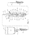
- FIG. 1 is a partially cut away side view of apparatus in accordance with the present invention.
- burette apparatus adapted for use with a conventional sterile liquid supply bag 10, having a delivery spigot 11 and a septum-covered injection spigot 12, and adapted to be suspended on an infusion stand by means of integrally formed suspension tag 13.
- a delivery tube 14 connects the delivery spigot 11 to a burette assembly 15, via a fluid entry spigot 16 formed in an end cap assembly 17 of the burette assembly 15.
- the delivery tube 14 is closable by a valve clamp 20.
- the end cap assembly 17 is provided with a bypass spigot 21 adapted to be connected back to the delivery tube 14 at Y-piece 22, usually pressed closed by closure clip 23, to allow an override for adding liquid to the burette when the fluid entry spigot 16 is occluded as hereinafter described.
- the end cap assembly 17 is also provided with a utility spigot 24, in this example providing a sterile vent 25 through microporous cap 26, and an injection point 27 for secondary fluid through septum 30.
- the end cap assembly 17 closes the upper end of a transparent, cylindrical burette body 31, into which extends a stainless steel tube extension 32 of the fluid entry spigot 16.
- the lower end of the burette body 31 is closed by a lower closure assembly 33 comprising an integral ball housing and seat 34 containing a floating check ball 35, and being in fluid communication with a transparent drip chamber 36 via a stainless steel tube 37.
- An outlet tube 40 passes from the drip chamber 36 to the patient via regulating clamp 41.
- a float assembly 42 is located in the burette body 31 and comprises a float body 43 having locating lugs 44 disposed about its periphery, and an extension rod 45 extending upwards, the extension rod 45 being constrained to the axis of the burette body 31 by guide plate 46.
- the guide plate 46 has passages 47 to permit free fluid passage thereby.
- the upper end of the extension rod 45 is provided with a resilient cup 50 adapted to engage the open end of the stainless steel tube extension 32.
- the bag 10 is fitted to the burette assembly 15 and the flow is commenced to purge the system.
- the cannula assembly (not shown) is purged in the usual manner and fitted to the patient.
- the regulating clamp is adjusted to the desired drip rate, as is the case with a conventional burette.
- the float body 43 As the fluid level drops in the burette assembly 15, the float body 43 also drops, pulling the cup 50 off the stainless steel tube extension 32.
- the stainless steel tube extension 32 clears the meniscus of any fluid in the cup, the liquid can flow into the burette assembly 15 until the stainless steel tube extension 32 seals against the cup 50 again.
- the range of volume in the apparatus is 2.5 ml to 11 ml, which, over the diameter of the burette body, represents very much less of a head variation than that imposed by the remaining components downstream such as the drip chamber 36.
- Apparatus in accordance with the foregoing embodiment has several particular advantages. By virtue of its operation as a closed system requiring a minimum of intervention, the apparatus is usable under a wide range of conditions generally considered as adverse for IV administration, such as underwater to SCUBA divers or in low gravity conditions. Since the apparatus is self regulating, the addition of secondary fluids via the side port septum does not affect the care regime insofar as nurse visits is concerned, since the apparatus will recommence primary fluid flow when the level of secondary fluid allows the float to pull the primary valve open. The apparatus is amenable to vented or unvented use.
Landscapes
- Health & Medical Sciences (AREA)
- Vascular Medicine (AREA)
- Engineering & Computer Science (AREA)
- Anesthesiology (AREA)
- Biomedical Technology (AREA)
- Heart & Thoracic Surgery (AREA)
- Hematology (AREA)
- Life Sciences & Earth Sciences (AREA)
- Animal Behavior & Ethology (AREA)
- General Health & Medical Sciences (AREA)
- Public Health (AREA)
- Veterinary Medicine (AREA)
- Infusion, Injection, And Reservoir Apparatuses (AREA)
- Steroid Compounds (AREA)
- Organic Low-Molecular-Weight Compounds And Preparation Thereof (AREA)
- Auxiliary Devices For And Details Of Packaging Control (AREA)
- Processing And Handling Of Plastics And Other Materials For Molding In General (AREA)
- Medicines Containing Plant Substances (AREA)
Claims (19)
- Bürettenvorrichtung mit:dadurch gekennzeichnet, dass die Steuereinrichtung einen Schwimmer (43) mit einem Becherabschnitt (50) zum Schließen des Einlasses bei Berührung mit der Flüssigkeitsoberfläche, die in dem Becher vorliegt, aufweist.einem Bürettenkörperelement (31) mit einem Einlass (16, 32), der an eine Flüssigkeitsquelle angeschlossen ist und mit einem Auslass (36, 37), durch den Flüssigkeit in einen Abflussschlauch fließen kann;einer Steuereinrichtung (42, 50) zur Aufrechterhaltung des Flüssigkeitsspiegels in dem Körperelement;einer Messeinrichtung (36) zur Steuerung der Fließgeschwindigkeit der Flüssigkeit durch den Auslass, und einer Auslassverschlusseinrichtung (34, 35), die bei einem minimalen Spiegel der Flüssigkeit in dem Körperelement betreibbar ist,
- Bürettenvorrichtung nach Anspruch 1, bei der das Bürettenkörperelement (31) einen zylindrischen Abschnitt, der im wesentlichen vertikal gelagert ist und Verschlussabschnitte am oberen (17) und unteren (33) Ende aufweist, die jeweils den Einlass und Auslass einschließen.
- Bürettenvorrichtung nach Anspruch 2, bei der Verschlussabschnitt am oberen Ende mit einem sekundären Flüssigkeitsinjektionspunkt (24) ausgestattet ist.
- Bürettenvorrichtung nach Anspruch 1, bei der der Einlass (16) zum Körperelement einen Einlassaufbau aufweist, der eine Flüssigkeitsverbindung zu einer beutelartigen Flüssigkeitsquelle über einen biegsamen Schlauch (14) zum Verbinden des Einlasses mit einem Auslass des Beutels bereitstellt.
- Bürettenvorrichtung nach Anspruch 4, bei der der Einlassaufbau eine Einlass-Stichleitung (32) aufweist, die in das Körperelement vorspringt und zum Eintritt in den Becherabschnitt auf dem Flüssigkeitsspiegel vorgesehen ist, wobei die Stichleitung zum Abdichten gegen die gespannte Oberfläche der Flüssigkeit, die in dem Becher (50) vorliegt, vorgesehen ist, um das Fließen dadurch hindurch im wesentlichen anzuhalten.
- Bürettenvorrichtung nach Anspruch 1, bei der das Körperelement (31) über dem Flüssigkeitsspiegel ein Fassungsvermögen aufweist, um einen sekundären Flüssigkeitszusatz aufzunehmen.
- Bürettenvorrichtung nach Anspruch 6, bei der der Becherabschnitt (50) einen Gummi oder einen anderen elastischen Sitz zum dichtenden Verschließen des Einlasses (32) aufweist, wenn er gegen diesen durch über den maximalen Spiegel hinausgehende Flüssigkeit gedrückt wird.
- Bürettenvorrichtung nach Anspruch 1, bei der der Auslass einen Teil eines Auslassaufbaus (36, 37) aufweist, der in einem Endverschlussabschnitt (33) des Körperelementes ausgebildet ist.
- Bürettenvorrichtung nach Anspruch 8, bei der die Messeinrichtung (36) ein variables Ventil oder Öffnung aufweist.
- Bürettenvorrichtung nach Anspruch 8, bei der die Auslassverschlusseinrichtung (34, 35) in Reaktion auf das Abfallen des Flüssigkeitsspiegels unter einen vorbestimmten minimalen Flüssigkeitsspiegel in dem Körperelement betreibbar ist.
- Bürettenvorrichtung nach Anspruch 10, bei der die Auslassverschlusseinrichtung einen festgehaltenen Schwimmerball (35) zum dichtbaren Eingriff eines Sitzes (34), der um den Auslass herum angeordnet ist, aufweist.
- Bürettenvorrichtung nach Anspruch 10, bei der die Auslassverschlusseinrichtung einen Dichtungsabschnitt des Schwimmers (35) zum dichtenden Eingriff des Auslasses aufweist, wenn der Schwimmer unter einen vorbestimmten Spiegel fällt.
- Bürettenvorrichtung nach Anspruch 9, bei der die Messeinrichtung zur Steuerung der Fließgeschwindigkeit der Flüssigkeit durch den Auslass eine variable Klemme (41) aufweist, die an dem Abflussschlauch angeordnet ist.
- Bürettenvorrichtung nach Anspruch 13, bei der die Messeinrichtung eine Durchflussmesseinrichtung (36) aufweist, wodurch eine Anzeige der Fließgeschwindigkeit bereitgestellt wird.
- Bürettenvorrichtung nach Anspruch 14, bei der die Durchflussmesseinrichtung einen sichtbaren Tropfanzeiger (36, 37) aufweist, der einen Teil des Auslassaufbaus bildet.
- Bürettenvorrichtung nach Anspruch 1, bei der ein Luftraum in dem Körperelement zur Atmosphäre entlüftet wird (25).
- Bürettenvorrichtung nach Anspruch 1, bei der ein Luftraum in dem Körperelement zu einem entsprechenden Luftraum in der Flüssigkeitsquelle entlüftet wird (21).
- Bürettenvorrichtung nach Anspruch 17, bei der die Verbindung zwischen der Flüssigkeitsquelle und dem Einlass mittels einer komplementären Verbindungseinrichtung (17) hergestellt wird, die Mittel zum Entlüften des Luftraums in dem Körperelement (21) zum entsprechenden Luftraum in der Flüssigkeitsquelle aufweist.
- Bürettenvorrichtung nach Anspruch 1, bei der die Verbindung zwischen der Flüssigkeitsquelle und dem Einlass mittels einer komplementären Anschlusseinrichtung (17) hergestellt wird, die eine selektiv betreibbare Umgehungs-Einrichtung (21, 23) aufweist, wodurch manuell ein selektiver Flüssigkeitsstrom in das Körperelement ermöglicht wird.
Applications Claiming Priority (4)
| Application Number | Priority Date | Filing Date | Title |
|---|---|---|---|
| AUPM8382A AUPM838294A0 (en) | 1994-09-26 | 1994-09-26 | Auto refill not vented to atmosphere vented burette |
| AUPM8382/94 | 1994-09-26 | ||
| AUPM838294 | 1994-09-26 | ||
| PCT/AU1995/000634 WO1996009845A1 (en) | 1994-09-26 | 1995-09-26 | Burette apparatus |
Publications (3)
| Publication Number | Publication Date |
|---|---|
| EP0783333A1 EP0783333A1 (de) | 1997-07-16 |
| EP0783333A4 EP0783333A4 (de) | 1998-06-17 |
| EP0783333B1 true EP0783333B1 (de) | 2001-12-05 |
Family
ID=3782901
Family Applications (1)
| Application Number | Title | Priority Date | Filing Date |
|---|---|---|---|
| EP95933242A Expired - Lifetime EP0783333B1 (de) | 1994-09-26 | 1995-09-26 | Bürettenvorrichtung |
Country Status (11)
| Country | Link |
|---|---|
| US (1) | US5885532A (de) |
| EP (1) | EP0783333B1 (de) |
| JP (1) | JPH10509060A (de) |
| AT (1) | ATE209934T1 (de) |
| AU (1) | AUPM838294A0 (de) |
| CA (1) | CA2200584C (de) |
| DE (1) | DE69524435T2 (de) |
| DK (1) | DK0783333T3 (de) |
| ES (1) | ES2169766T3 (de) |
| PT (1) | PT783333E (de) |
| WO (1) | WO1996009845A1 (de) |
Families Citing this family (10)
| Publication number | Priority date | Publication date | Assignee | Title |
|---|---|---|---|---|
| US6551279B1 (en) * | 2000-05-25 | 2003-04-22 | Oratec Interventions, Inc. | Infusion dispenser with adjustable flow rate regulator |
| KR20040020484A (ko) * | 2002-08-30 | 2004-03-09 | 황승준 | 속도조절이 가능한 뷰렛 |
| WO2007041787A1 (en) | 2005-10-13 | 2007-04-19 | Analytica Limited | A burette |
| US20070246463A1 (en) * | 2006-03-27 | 2007-10-25 | The Hoffman Group, Llc | Moduler fluid containment unit |
| US8221366B2 (en) * | 2007-09-05 | 2012-07-17 | Integra Lifesciences Corporation | Volume limiting bodily fluid drainage system |
| WO2014036589A1 (en) * | 2012-09-05 | 2014-03-13 | Analytica Limited | A burette |
| JP6385800B2 (ja) * | 2014-11-11 | 2018-09-05 | 日本電子株式会社 | 液体吸引具、液体供給ユニット及び自動分析装置 |
| ES2964749T3 (es) * | 2015-12-10 | 2024-04-09 | Nipro Corp | Dispositivo de administración de líquido médico |
| TWI656892B (zh) * | 2018-05-07 | 2019-04-21 | 楊為任 | 精密靜脈輸液套管流量控制裝置 |
| US12383669B1 (en) * | 2024-06-24 | 2025-08-12 | Stratos MedTech Holdings Pty Ltd | Gravity-fed burette system |
Family Cites Families (14)
| Publication number | Priority date | Publication date | Assignee | Title |
|---|---|---|---|---|
| US2558387A (en) * | 1946-01-28 | 1951-06-26 | Gen Controls Co | Liquid sampler |
| US3207372A (en) * | 1962-09-21 | 1965-09-21 | Sterilon Corp | Intravenous feeding apparatus |
| US3929157A (en) * | 1974-06-17 | 1975-12-30 | Juan R Serur | Fluid flow regulator |
| IL45485A (en) * | 1974-08-18 | 1976-10-31 | Yarden Medical Eng Ltd | Constant-flow device for intravenous infusion set |
| US3989043A (en) * | 1974-12-23 | 1976-11-02 | John Dimeff | Automatic flow control and automatic shut off for intravenous feeders |
| US3949745A (en) * | 1975-08-28 | 1976-04-13 | Howell William L | Parenteral fluid administration set |
| US4096879A (en) * | 1976-08-19 | 1978-06-27 | International Biomedical Laboratories, Inc. | Adjustable fluid flow regulator |
| US4256103A (en) * | 1978-10-11 | 1981-03-17 | James Paxinos | Automatic sequential fluid flow apparatus |
| US4449976A (en) * | 1981-05-21 | 1984-05-22 | Baxter Travenol Laboratories, Inc. | Device for preserving continuity of intravenous flow |
| JPS59500254A (ja) * | 1982-01-27 | 1984-02-23 | オ−スチン,ジヨ−ジ アルフレツド ブライスビ− | 装置 |
| US4623333A (en) * | 1984-09-28 | 1986-11-18 | Fried Steven J | Fried-Grant rapid solution administration set with integral heat exchanger |
| GB2178135B (en) * | 1985-07-25 | 1988-11-30 | Cheng Kuo Fang | A controlling device for an intravenous feeding or medicating device |
| US4959053A (en) * | 1988-01-08 | 1990-09-25 | Jang Cheng Houng | Automatic stopping device for the intravenous drip |
| US5059173A (en) * | 1990-04-04 | 1991-10-22 | Sacco John J | IV apparatus |
-
1994
- 1994-09-26 AU AUPM8382A patent/AUPM838294A0/en not_active Abandoned
-
1995
- 1995-03-26 US US08/817,341 patent/US5885532A/en not_active Expired - Lifetime
- 1995-09-26 CA CA002200584A patent/CA2200584C/en not_active Expired - Lifetime
- 1995-09-26 ES ES95933242T patent/ES2169766T3/es not_active Expired - Lifetime
- 1995-09-26 PT PT95933242T patent/PT783333E/pt unknown
- 1995-09-26 JP JP8511202A patent/JPH10509060A/ja active Pending
- 1995-09-26 AT AT95933242T patent/ATE209934T1/de not_active IP Right Cessation
- 1995-09-26 DE DE69524435T patent/DE69524435T2/de not_active Expired - Lifetime
- 1995-09-26 DK DK95933242T patent/DK0783333T3/da active
- 1995-09-26 EP EP95933242A patent/EP0783333B1/de not_active Expired - Lifetime
- 1995-09-26 WO PCT/AU1995/000634 patent/WO1996009845A1/en not_active Ceased
Also Published As
| Publication number | Publication date |
|---|---|
| PT783333E (pt) | 2002-05-31 |
| EP0783333A1 (de) | 1997-07-16 |
| US5885532A (en) | 1999-03-23 |
| WO1996009845A1 (en) | 1996-04-04 |
| EP0783333A4 (de) | 1998-06-17 |
| AUPM838294A0 (en) | 1994-10-20 |
| ES2169766T3 (es) | 2002-07-16 |
| JPH10509060A (ja) | 1998-09-08 |
| CA2200584A1 (en) | 1996-04-04 |
| DE69524435T2 (de) | 2002-08-01 |
| CA2200584C (en) | 2007-01-30 |
| DK0783333T3 (da) | 2002-04-08 |
| DE69524435D1 (de) | 2002-01-17 |
| ATE209934T1 (de) | 2001-12-15 |
Similar Documents
| Publication | Publication Date | Title |
|---|---|---|
| US5730730A (en) | Liquid flow rate control device | |
| US5423346A (en) | Fluid container shut off valve | |
| US6213986B1 (en) | Liquid flow rate control device | |
| US4941875A (en) | I.V. system for successive administration of two or more solutions at different rates | |
| US4142523A (en) | Flow control device for the intravenous administration of liquids | |
| EP0343286B1 (de) | Volumetrische Pumpe für parenterale Perfusion | |
| US4623343A (en) | Parenteral fluid administration apparatus and method | |
| US4136693A (en) | Constant flow I.V. device | |
| US4588396A (en) | Apparatus for gravity feed of liquid under constant hydrostatic pressure | |
| US4173222A (en) | Apparatus for controllably administering a parenteral fluid | |
| US4613325A (en) | Flow rate sensing device | |
| US5308333A (en) | Air eliminating intravenous infusion pump set | |
| WO1997047339A1 (en) | Gravity infusion set for medical infusions | |
| EP0783333B1 (de) | Bürettenvorrichtung | |
| US3963024A (en) | Fluid flow regulator | |
| US3844283A (en) | Apparatus for aseptically dispensing a measured volume of liquid | |
| NO147293B (no) | Implanterbar vaeskestroemregulator for medikamentinfusjon fra en innretning for regulert tilfoersel av medikament under trykk og et implanterbart infusjonsapparat som omfatter en slik trykkregulator | |
| HRP20021016A2 (en) | Infusion of liquids into the human or animal body | |
| EP0911045A2 (de) | Medizinischer Farbstoff Abgabevorrichtung | |
| US3965895A (en) | Apparatus for controlled volume and rate administration of liquids | |
| JPH03173579A (ja) | 点滴装置 | |
| US6183447B1 (en) | Medical dye delivery system | |
| EP0041182B1 (de) | Gerät für die parenterale Verabreichung von Flüssigkeiten mit gleichmässiger und einstellbarer Abgabemenge | |
| JPH0445184B2 (de) | ||
| US2989052A (en) | Parenteral fluid equipment |
Legal Events
| Date | Code | Title | Description |
|---|---|---|---|
| PUAI | Public reference made under article 153(3) epc to a published international application that has entered the european phase |
Free format text: ORIGINAL CODE: 0009012 |
|
| 17P | Request for examination filed |
Effective date: 19970424 |
|
| AK | Designated contracting states |
Kind code of ref document: A1 Designated state(s): AT BE CH DE DK ES FR GB GR IE IT LI LU MC NL PT SE |
|
| A4 | Supplementary search report drawn up and despatched | ||
| AK | Designated contracting states |
Kind code of ref document: A4 Designated state(s): AT BE CH DE DK ES FR GB GR IE IT LI LU MC NL PT SE |
|
| GRAG | Despatch of communication of intention to grant |
Free format text: ORIGINAL CODE: EPIDOS AGRA |
|
| 17Q | First examination report despatched |
Effective date: 20010223 |
|
| GRAG | Despatch of communication of intention to grant |
Free format text: ORIGINAL CODE: EPIDOS AGRA |
|
| GRAH | Despatch of communication of intention to grant a patent |
Free format text: ORIGINAL CODE: EPIDOS IGRA |
|
| GRAH | Despatch of communication of intention to grant a patent |
Free format text: ORIGINAL CODE: EPIDOS IGRA |
|
| GRAA | (expected) grant |
Free format text: ORIGINAL CODE: 0009210 |
|
| AK | Designated contracting states |
Kind code of ref document: B1 Designated state(s): AT BE CH DE DK ES FR GB GR IE IT LI LU MC NL PT SE |
|
| REF | Corresponds to: |
Ref document number: 209934 Country of ref document: AT Date of ref document: 20011215 Kind code of ref document: T |
|
| REG | Reference to a national code |
Ref country code: CH Ref legal event code: EP |
|
| REG | Reference to a national code |
Ref country code: GB Ref legal event code: IF02 |
|
| REG | Reference to a national code |
Ref country code: IE Ref legal event code: FG4D |
|
| REF | Corresponds to: |
Ref document number: 69524435 Country of ref document: DE Date of ref document: 20020117 |
|
| REG | Reference to a national code |
Ref country code: DK Ref legal event code: T3 |
|
| REG | Reference to a national code |
Ref country code: CH Ref legal event code: NV Representative=s name: HEPP, WENGER & RYFFEL AG |
|
| ET | Fr: translation filed | ||
| REG | Reference to a national code |
Ref country code: PT Ref legal event code: SC4A Free format text: AVAILABILITY OF NATIONAL TRANSLATION Effective date: 20020305 |
|
| REG | Reference to a national code |
Ref country code: ES Ref legal event code: FG2A Ref document number: 2169766 Country of ref document: ES Kind code of ref document: T3 |
|
| REG | Reference to a national code |
Ref country code: GR Ref legal event code: EP Ref document number: 20020400909 Country of ref document: GR |
|
| PLBE | No opposition filed within time limit |
Free format text: ORIGINAL CODE: 0009261 |
|
| STAA | Information on the status of an ep patent application or granted ep patent |
Free format text: STATUS: NO OPPOSITION FILED WITHIN TIME LIMIT |
|
| 26N | No opposition filed | ||
| PGFP | Annual fee paid to national office [announced via postgrant information from national office to epo] |
Ref country code: NL Payment date: 20050925 Year of fee payment: 11 |
|
| PGFP | Annual fee paid to national office [announced via postgrant information from national office to epo] |
Ref country code: PT Payment date: 20050926 Year of fee payment: 11 |
|
| PGFP | Annual fee paid to national office [announced via postgrant information from national office to epo] |
Ref country code: SE Payment date: 20050928 Year of fee payment: 11 Ref country code: MC Payment date: 20050928 Year of fee payment: 11 Ref country code: IE Payment date: 20050928 Year of fee payment: 11 Ref country code: GR Payment date: 20050928 Year of fee payment: 11 Ref country code: CH Payment date: 20050928 Year of fee payment: 11 Ref country code: AT Payment date: 20050928 Year of fee payment: 11 |
|
| PGFP | Annual fee paid to national office [announced via postgrant information from national office to epo] |
Ref country code: DK Payment date: 20050929 Year of fee payment: 11 |
|
| PGFP | Annual fee paid to national office [announced via postgrant information from national office to epo] |
Ref country code: ES Payment date: 20051014 Year of fee payment: 11 |
|
| PGFP | Annual fee paid to national office [announced via postgrant information from national office to epo] |
Ref country code: LU Payment date: 20051031 Year of fee payment: 11 |
|
| PGFP | Annual fee paid to national office [announced via postgrant information from national office to epo] |
Ref country code: BE Payment date: 20051125 Year of fee payment: 11 |
|
| PG25 | Lapsed in a contracting state [announced via postgrant information from national office to epo] |
Ref country code: IE Free format text: LAPSE BECAUSE OF NON-PAYMENT OF DUE FEES Effective date: 20060926 Ref country code: AT Free format text: LAPSE BECAUSE OF NON-PAYMENT OF DUE FEES Effective date: 20060926 |
|
| PG25 | Lapsed in a contracting state [announced via postgrant information from national office to epo] |
Ref country code: SE Free format text: LAPSE BECAUSE OF NON-PAYMENT OF DUE FEES Effective date: 20060927 |
|
| PG25 | Lapsed in a contracting state [announced via postgrant information from national office to epo] |
Ref country code: MC Free format text: LAPSE BECAUSE OF NON-PAYMENT OF DUE FEES Effective date: 20060930 Ref country code: LI Free format text: LAPSE BECAUSE OF NON-PAYMENT OF DUE FEES Effective date: 20060930 Ref country code: CH Free format text: LAPSE BECAUSE OF NON-PAYMENT OF DUE FEES Effective date: 20060930 Ref country code: BE Free format text: LAPSE BECAUSE OF NON-PAYMENT OF DUE FEES Effective date: 20060930 |
|
| PG25 | Lapsed in a contracting state [announced via postgrant information from national office to epo] |
Ref country code: DK Free format text: LAPSE BECAUSE OF NON-PAYMENT OF DUE FEES Effective date: 20061002 |
|
| PG25 | Lapsed in a contracting state [announced via postgrant information from national office to epo] |
Ref country code: PT Free format text: LAPSE BECAUSE OF NON-PAYMENT OF DUE FEES Effective date: 20070326 |
|
| PG25 | Lapsed in a contracting state [announced via postgrant information from national office to epo] |
Ref country code: NL Free format text: LAPSE BECAUSE OF NON-PAYMENT OF DUE FEES Effective date: 20070401 |
|
| REG | Reference to a national code |
Ref country code: PT Ref legal event code: MM4A Free format text: LAPSE DUE TO NON-PAYMENT OF FEES Effective date: 20070326 Ref country code: DK Ref legal event code: EBP |
|
| REG | Reference to a national code |
Ref country code: CH Ref legal event code: PL |
|
| EUG | Se: european patent has lapsed | ||
| NLV4 | Nl: lapsed or anulled due to non-payment of the annual fee |
Effective date: 20070401 |
|
| REG | Reference to a national code |
Ref country code: IE Ref legal event code: MM4A |
|
| REG | Reference to a national code |
Ref country code: ES Ref legal event code: FD2A Effective date: 20060927 |
|
| BERE | Be: lapsed |
Owner name: *NOONBEACH PTY. LTD Effective date: 20060930 |
|
| PG25 | Lapsed in a contracting state [announced via postgrant information from national office to epo] |
Ref country code: ES Free format text: LAPSE BECAUSE OF NON-PAYMENT OF DUE FEES Effective date: 20060927 |
|
| PG25 | Lapsed in a contracting state [announced via postgrant information from national office to epo] |
Ref country code: LU Free format text: LAPSE BECAUSE OF NON-PAYMENT OF DUE FEES Effective date: 20060926 |
|
| PG25 | Lapsed in a contracting state [announced via postgrant information from national office to epo] |
Ref country code: GR Free format text: LAPSE BECAUSE OF NON-PAYMENT OF DUE FEES Effective date: 20070404 |
|
| PGFP | Annual fee paid to national office [announced via postgrant information from national office to epo] |
Ref country code: FR Payment date: 20140829 Year of fee payment: 20 Ref country code: GB Payment date: 20140910 Year of fee payment: 20 |
|
| PGFP | Annual fee paid to national office [announced via postgrant information from national office to epo] |
Ref country code: IT Payment date: 20140909 Year of fee payment: 20 |
|
| PGFP | Annual fee paid to national office [announced via postgrant information from national office to epo] |
Ref country code: DE Payment date: 20140930 Year of fee payment: 20 |
|
| REG | Reference to a national code |
Ref country code: DE Ref legal event code: R071 Ref document number: 69524435 Country of ref document: DE |
|
| REG | Reference to a national code |
Ref country code: GB Ref legal event code: PE20 Expiry date: 20150925 |
|
| PG25 | Lapsed in a contracting state [announced via postgrant information from national office to epo] |
Ref country code: GB Free format text: LAPSE BECAUSE OF EXPIRATION OF PROTECTION Effective date: 20150925 |