EP0783199B1 - Verschienungssystem für den Zwischenkreis eines Stromrichters - Google Patents
Verschienungssystem für den Zwischenkreis eines Stromrichters Download PDFInfo
- Publication number
- EP0783199B1 EP0783199B1 EP97100097A EP97100097A EP0783199B1 EP 0783199 B1 EP0783199 B1 EP 0783199B1 EP 97100097 A EP97100097 A EP 97100097A EP 97100097 A EP97100097 A EP 97100097A EP 0783199 B1 EP0783199 B1 EP 0783199B1
- Authority
- EP
- European Patent Office
- Prior art keywords
- connection
- phase
- bus bar
- converter
- connections
- Prior art date
- Legal status (The legal status is an assumption and is not a legal conclusion. Google has not performed a legal analysis and makes no representation as to the accuracy of the status listed.)
- Expired - Lifetime
Links
Images


Classifications
-
- H—ELECTRICITY
- H02—GENERATION; CONVERSION OR DISTRIBUTION OF ELECTRIC POWER
- H02M—APPARATUS FOR CONVERSION BETWEEN AC AND AC, BETWEEN AC AND DC, OR BETWEEN DC AND DC, AND FOR USE WITH MAINS OR SIMILAR POWER SUPPLY SYSTEMS; CONVERSION OF DC OR AC INPUT POWER INTO SURGE OUTPUT POWER; CONTROL OR REGULATION THEREOF
- H02M7/00—Conversion of AC power input into DC power output; Conversion of DC power input into AC power output
- H02M7/003—Constructional details, e.g. physical layout, assembly, wiring or busbar connections
-
- H—ELECTRICITY
- H05—ELECTRIC TECHNIQUES NOT OTHERWISE PROVIDED FOR
- H05K—PRINTED CIRCUITS; CASINGS OR CONSTRUCTIONAL DETAILS OF ELECTRIC APPARATUS; MANUFACTURE OF ASSEMBLAGES OF ELECTRICAL COMPONENTS
- H05K7/00—Constructional details common to different types of electric apparatus
- H05K7/14—Mounting supporting structure in casing or on frame or rack
- H05K7/1422—Printed circuit boards receptacles, e.g. stacked structures, electronic circuit modules or box like frames
- H05K7/1427—Housings
- H05K7/1432—Housings specially adapted for power drive units or power converters
- H05K7/14329—Housings specially adapted for power drive units or power converters specially adapted for the configuration of power bus bars
Definitions
- the invention relates to the field of power electronics. It goes out from a busbar system for the intermediate circuit of a converter according to the preamble of the first claim.
- Such a rail system is e.g. in the article "GTO high-performance converter for traction vehicles with three-phase drive ", ABBtechnik 4/1995, pages 4-13.
- Power converter e.g. for electrically powered Locomotives have a DC link. On this The DC link is on the one hand a line converter - this is missing if that Network is a DC network - and on the other hand, a generally multi-phase Drive converter connected.
- the rail system forms the electrical connection between the output of the line converter - or the contact wire in a DC voltage network - and the power semiconductor switches or modules of the drive converter.
- the power semiconductor switch has a transition from conventional thyristors via the turn-off thyristors (GTOs) to the IGBTs (Insulated gate bipolar transistors).
- the IGBTs are general integrated in a module. For higher performances there will be several Modules connected in parallel.
- different Services would be a modular and easily scalable structure of the Power converter and thus also the busbar system desirable.
- busbar system should be constructed as low inductively as possible be because of the ever increasing requirements for possible network interference higher switching frequencies are preferred.
- a busbar system comprising a plus and a minus connection as well Phase connections, with the pole plates and the phase connections in the order Plus connection, minus connection, phase connections with the interposition of insulation elements stacked on top of each other and on a support are known from WO-A-9 414 227.
- the object of the present invention is to specify a busbar system, which is simple and low-inductively constructed and which with regard to different services are easily scalable. This task is with a Rail system of the type mentioned by the features of the first Claim solved.
- the plus and minus connection of the intermediate circuit each comprise a grid-shaped pole plate and the phase connection or phases are built in a rail shape.
- the sheets and rails are in in the order of plus, minus connection, phase connection or minus, plus connection, Phase connection with the interposition of insulation elements stacked mounted on a carrier.
- a preferred embodiment is characterized in that the Pole sheets bent or welded in the area of the grid cutouts Have tabs, which with the "U" -shaped profile rails of the phase connection (s) interact. This allows power semiconductor switches or modules by simply attaching them to the tabs and the legs of the U-rails are contacted.
- the advantage of the invention is not only that Fact that the rail system performs in a simple manner Power converters of different power can be adjusted, but by the flat structure of the pole plates is also obtained with a low inductance Construction.
- Figure 1 shows a plan view of a rail system according to the invention. This is suitable for the intermediate circuit busbar system of a converter.
- the DC link busbar of a converter is the electrical Contacts between the intermediate circuit of a U or I converter and the power semiconductor switches or power semiconductor modules and the phases or Load connections made.
- Figure 1 shows an embodiment of a DC link busbar system of a three-phase converter with braking unit, as he e.g. is used for traction applications.
- phase rails lead to the phase connections of the load, e.g. a drive motor. in the The following is no longer between the brake actuator connection rail and the phase rail distinguished, since both have the same mechanical structure.
- Figures 5 and 6 show the pole plates 1.1 and 1.2 in detail. They are lattice-shaped designed and include recesses 10. In the area of the recesses 10 and along the sides, the pole plates 1.1 and 1.2 project at right angles, e.g. curved tabs 5. For an even more compact design the tabs can also be welded on. Note that the two Pole plates 1.1 and 1.2 basically have the same structure, but twisted be assembled by turning one of them 180 ° (otherwise, as the pole plates are shown in Figures 5 and 6).
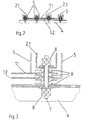
- phase rails have a "U" -shaped profile. Rejuvenate on one side it yourself (see Figure 4). Pole plates and phase rails are now on top of each other stacked and with screws or threaded rods 7, which by Appropriate mounting holes 9 are passed through on the carrier 4th attached. This results in an arrangement as shown in section in Figure 2 is shown. The distance between the pole plates and phase connections is chosen so that no breakthrough can occur. In addition, as in the detailed view of Figure 3 can be seen, vortex-shaped insulation elements or isolation rosettes 6 are provided between the pole plates and phase connections.
- the threaded rod 7 is preferably made of an electrically insulating Material, e.g. Plastic, manufactured. The same applies to the nuts 8, by means of which is the stack of pole sheets and phase rails on the carrier is screwed tight.
- the pole plates have a lattice-like structure. How As shown above, at least one module is placed over each bar of the grid or switches in the corresponding connections of the pole plates and phase connections plugged. This allows the rail system to match the performance of a Adjust converter by moving it from left to right in Figures 5 and 6 right is extended so that a larger number of recesses is created. This results in a rail system, which according to FIG. 1 simply goes up is extended. It is therefore possible to use a whole family of converters to equip similarly constructed rail systems by extending them or shortened.
- pole plates are essentially flat, there is a comparative one small inductance. This is especially true with regard to higher ones Switching frequencies and steeper switching edges are a great advantage.
- the rail system according to the invention thus allows the construction of a converter, which not only is designed to be low inductive, but also simple in terms of performance can be scaled.
Landscapes
- Engineering & Computer Science (AREA)
- Microelectronics & Electronic Packaging (AREA)
- Power Engineering (AREA)
- Power Conversion In General (AREA)
- Rectifiers (AREA)
- Inverter Devices (AREA)
- Electric Propulsion And Braking For Vehicles (AREA)
Description
- Fig. 1
- Eine Aufsicht auf ein erfindungsgemässes Verschienungssystem;
- Fig. 2
- Das Verschienungssystem nach Figur 1 im Schnitt entlang der in Figur 1 strichpunktiert dargestellten Linie;
- Fig. 3
- Eine Detailansicht eines erfindungsgemässen Verschienungssystems von der Seite;
- Fig. 4
- Eine Aufsicht auf eine Phasenschiene;
- Fig. 5
- Eine Aufsicht auf ein erstes Polblech;
- Fig. 6
- Eine Aufsicht auf ein zweites Polblech.
- 1.1, 1.2
- Polbleche
- 2.1, 2.2, 2.3
- Phasenschienen
- 3
- Bremsstelleranschluss
- 4
- Träger
- 5
- Lasche
- 6
- Isolierelement
- 7
- Gewindestange
- 8
- Mutter
- 9
- Befestigungsloch
- 10
- Aussparung
Claims (4)
- Verschienungssystem für eine Zwischenkreisverschienung eines Stromrichters, umfassend einen Plus- und einen Minusanschluss sowie mindestens einen Phasenanschluss, wobei der Plus- und der Minusanschluss aus einem gitterförmigen, mit Aussparungen (10) versehenen Polblech (1.1, 1.2) bestehen, dass der oder jeder Phasenanschluss schienenförmig ausgebildet ist und wobei die Polbleche (1.1, 1.2) und die schienenförmigen Phasenanschlüsse (2.1,..,2.3) in der Reihenfolge Plusanschluss, Minusanschluss, Phasenanschluss/ Phasenanschlüsse oder Minusanschluss, Plusanschluss, Phasenanschluss/Phasenanschlüsse unter Zwischenfügung von Isolationselementen (6) aufeinander gestapelt und auf einem Träger (4) befestigt sind.
- Verschienungssystem nach Anspruch 1, wobei die Stege der gitterförmigen Polbleche (1.1, 1.2) im Bereich der Aussparungen (10) im wesentlichen rechtwinklig abstehende Laschen (5) aufweisen, wobei der oder jeder schienenförmige Phasenanschluss (2.1,..,2.3) im wesentlichen ein "U-förmiges Profil aufweist und wobei die Laschen (5) der Polbleche (1.1, 1.2) mit den benachbarten Schenkeln des "U"-förmigen Phasenanschlusses zur Aufnahme und elektrischen Kontaktierung von Leistungshalbleiterschaltern oder Leistungshalbleiterschaltermodulen zusammenwirken.
- Verschienungssystem nach Anspruch 1 oder 2, wobei eine Anzahl der Aussparungen (10) der Polbleche nach Massgabe der Anzahl Phasenanschlüsse und einer geforderten Leistung des Stromrichters bzw. einer Anzahl parallelgeschalteter Leistungshalbleiterschalter oder Leistungshalbleiterschaltermodulen gewählt ist.
- Stromrichter, insbesondere U-Umrichter, mit einen Zwischenkreis und daran angeschlossenen Brückenzweigen, wobei die elektrische Verbindung zwischen den Brückenzweigen und dem Zwischenkreis ein Verschienungssystem nach einem der vorstehenden Ansprüche umfasst.
Applications Claiming Priority (2)
| Application Number | Priority Date | Filing Date | Title |
|---|---|---|---|
| DE19600367 | 1996-01-08 | ||
| DE19600367A DE19600367A1 (de) | 1996-01-08 | 1996-01-08 | Verschienungssystem für den Zwischenkreis eines Stromrichters |
Publications (3)
| Publication Number | Publication Date |
|---|---|
| EP0783199A2 EP0783199A2 (de) | 1997-07-09 |
| EP0783199A3 EP0783199A3 (de) | 1998-12-02 |
| EP0783199B1 true EP0783199B1 (de) | 2002-04-10 |
Family
ID=7782273
Family Applications (1)
| Application Number | Title | Priority Date | Filing Date |
|---|---|---|---|
| EP97100097A Expired - Lifetime EP0783199B1 (de) | 1996-01-08 | 1997-01-07 | Verschienungssystem für den Zwischenkreis eines Stromrichters |
Country Status (3)
| Country | Link |
|---|---|
| EP (1) | EP0783199B1 (de) |
| JP (1) | JP3792814B2 (de) |
| DE (2) | DE19600367A1 (de) |
Families Citing this family (9)
| Publication number | Priority date | Publication date | Assignee | Title |
|---|---|---|---|---|
| DE19719648A1 (de) * | 1997-05-09 | 1998-11-12 | Abb Daimler Benz Transp | Stromrichter-Module mit einem Verschienungssystem für Leistungshalbleiterschalter |
| EP0895340A1 (de) * | 1997-07-31 | 1999-02-03 | Scholl Sun Power SSP S.A. | Gleichstrom-Wechselstrom Leistungswandler für elektrischen Fahrzeug |
| DE19833491A1 (de) | 1998-07-24 | 2000-02-03 | Siemens Ag | Niederinduktive Verschienung für einen Dreipunkt-Phasenbaustein |
| DE19851161A1 (de) * | 1998-11-06 | 2000-05-11 | Abb Daimler Benz Transp | Stromrichtergerät mit Gleich- und Wechselspannungsverschienung |
| DE19903522B4 (de) * | 1999-01-29 | 2007-06-14 | Alstom Power Conversion Gmbh | Anordnung zur niederinduktiven Führung hoher Ströme insbesondere für einen Stromrichter oder dergleichen |
| DE10260726B8 (de) | 2002-12-23 | 2014-12-18 | TRUMPF Hüttinger GmbH + Co. KG | Modulare Stromversorgung |
| DE102013204825A1 (de) * | 2013-03-19 | 2014-09-25 | Bombardier Transportation Gmbh | Stromschienenanordnung und Verfahren zur Herstellung einer Stromschienenanordnung |
| WO2018114688A1 (en) * | 2016-12-19 | 2018-06-28 | Abb Schweiz Ag | Laminated busbar for plug-in modules |
| CN111342408B (zh) * | 2020-03-03 | 2021-11-19 | 深圳辰汉技术有限公司 | 一种电力母排 |
Family Cites Families (8)
| Publication number | Priority date | Publication date | Assignee | Title |
|---|---|---|---|---|
| DE2925254C2 (de) * | 1979-06-22 | 1983-01-13 | Licentia Patent-Verwaltungs-Gmbh, 6000 Frankfurt | Halterung für Sammelschienen |
| DE3201296C2 (de) * | 1982-01-18 | 1986-06-12 | Institut elektrodinamiki Akademii Nauk Ukrainskoj SSR, Kiev | Transistoranordnung |
| US5365424A (en) * | 1991-07-10 | 1994-11-15 | Kenetech Windpower, Inc. | High power laminated bus assembly for an electrical switching converter |
| JPH06233554A (ja) * | 1993-01-28 | 1994-08-19 | Fuji Electric Co Ltd | インバータ装置 |
| US5422440A (en) * | 1993-06-08 | 1995-06-06 | Rem Technologies, Inc. | Low inductance bus bar arrangement for high power inverters |
| DE4338277C2 (de) * | 1993-07-17 | 1997-03-13 | Abb Patent Gmbh | Flüssigkeitsgekühltes Stromrichtermodul mit Beschaltungsbauelementen für abschaltbare Leistungshalbleiter |
| DE9403108U1 (de) * | 1994-02-24 | 1994-04-14 | Siemens AG, 80333 München | Niederinduktive Hochstromverschienung für Stromrichtermodule |
| DE29504290U1 (de) * | 1995-03-13 | 1995-06-22 | Siemens Ag | Stromrichtermodul |
-
1996
- 1996-01-08 DE DE19600367A patent/DE19600367A1/de not_active Withdrawn
-
1997
- 1997-01-07 EP EP97100097A patent/EP0783199B1/de not_active Expired - Lifetime
- 1997-01-07 DE DE59706920T patent/DE59706920D1/de not_active Expired - Fee Related
- 1997-01-08 JP JP00165797A patent/JP3792814B2/ja not_active Expired - Fee Related
Also Published As
| Publication number | Publication date |
|---|---|
| DE59706920D1 (de) | 2002-05-16 |
| EP0783199A2 (de) | 1997-07-09 |
| JP3792814B2 (ja) | 2006-07-05 |
| EP0783199A3 (de) | 1998-12-02 |
| JPH09219969A (ja) | 1997-08-19 |
| DE19600367A1 (de) | 1997-07-10 |
Similar Documents
| Publication | Publication Date | Title |
|---|---|---|
| EP1305874B1 (de) | Modular aufgebauter stromrichter | |
| DE4110339A1 (de) | Wechselrichtereinheit mit verbesserter stromleiterplattenkonfiguration | |
| DE102012201080B4 (de) | Leistungsmodul | |
| DE102006004031B3 (de) | Leistungshalbleitermodul mit Halbbrückenkonfiguration | |
| EP0877472B1 (de) | Stromrichter-Module mit einem Verschienungssystem für Leistungshalbleiterschalter | |
| DE2426229C3 (de) | Selbsttragender Träger für die Aufnahme von elektronischen Bauelementen | |
| EP3404818B1 (de) | Halbleiterschaltanordnung | |
| DE2354663A1 (de) | Stromrichter | |
| DE4402425A1 (de) | Wechselrichteranordnung | |
| EP0660496A2 (de) | Umrichteranordnung mit niederinduktivem Kommutierungskreis | |
| CH674434A5 (de) | ||
| EP0783199A2 (de) | Verschienungssystem für den Zwischenkreis eines Stromrichters | |
| DE69510317T2 (de) | Metallgekapselte gasisolierte Schaltvorrichtung | |
| EP1670131A2 (de) | Leistungshalbleitermodul mit verringerten parasitären Induktivitäten | |
| DE2016911A1 (de) | Geschlossene Sammelschienenleitung | |
| DE4023687A1 (de) | Stromrichteranordnung | |
| EP1305875A1 (de) | Niederinduktive verschienung für einen matrixumrichter | |
| EP2976832B1 (de) | Wechselrichter mit mindestens einer wechselrichterbrücke zwischen zwei busbars | |
| EP1782527B1 (de) | Vorrichtung zur speisung von hilfsbetriebeeinrichtungen für ein kraftstoffelektrisch angetriebenes fahrzeug | |
| WO2019042524A1 (de) | Stromrichter mit stromrichterzweig | |
| EP0989016B1 (de) | Stromrichterschaltung mit variabler Konfiguration für Traktionsanwendungen | |
| EP0236885A2 (de) | Druckgas-isolierter, dreiphasiger gekapselter Hochspannungs-Leistungsschalter | |
| EP1782526B1 (de) | Vorrichtung zur speisung von hilfsbetriebeeinrichtungen für ein kraftstoffelektrisch angetriebenes fahrzeug | |
| DE102023203529A1 (de) | Filter zur Entstörung eines Gleichspannungswandlers | |
| EP1619766B1 (de) | Sammelschienenanordnung für einen Niederspannungsschaltschrank |
Legal Events
| Date | Code | Title | Description |
|---|---|---|---|
| PUAI | Public reference made under article 153(3) epc to a published international application that has entered the european phase |
Free format text: ORIGINAL CODE: 0009012 |
|
| AK | Designated contracting states |
Kind code of ref document: A2 Designated state(s): CH DE FR IT LI |
|
| PUAL | Search report despatched |
Free format text: ORIGINAL CODE: 0009013 |
|
| AK | Designated contracting states |
Kind code of ref document: A3 Designated state(s): CH DE FR IT LI |
|
| 17P | Request for examination filed |
Effective date: 19990330 |
|
| RAP1 | Party data changed (applicant data changed or rights of an application transferred) |
Owner name: DAIMLERCHRYSLER AG |
|
| RAP1 | Party data changed (applicant data changed or rights of an application transferred) |
Owner name: DAIMLERCHRYSLER RAIL SYSTEMS GMBH |
|
| GRAG | Despatch of communication of intention to grant |
Free format text: ORIGINAL CODE: EPIDOS AGRA |
|
| 17Q | First examination report despatched |
Effective date: 20010529 |
|
| GRAG | Despatch of communication of intention to grant |
Free format text: ORIGINAL CODE: EPIDOS AGRA |
|
| GRAH | Despatch of communication of intention to grant a patent |
Free format text: ORIGINAL CODE: EPIDOS IGRA |
|
| GRAH | Despatch of communication of intention to grant a patent |
Free format text: ORIGINAL CODE: EPIDOS IGRA |
|
| GRAH | Despatch of communication of intention to grant a patent |
Free format text: ORIGINAL CODE: EPIDOS IGRA |
|
| GRAA | (expected) grant |
Free format text: ORIGINAL CODE: 0009210 |
|
| AK | Designated contracting states |
Kind code of ref document: B1 Designated state(s): CH DE FR IT LI |
|
| PG25 | Lapsed in a contracting state [announced via postgrant information from national office to epo] |
Ref country code: IT Free format text: LAPSE BECAUSE OF FAILURE TO SUBMIT A TRANSLATION OF THE DESCRIPTION OR TO PAY THE FEE WITHIN THE PRESCRIBED TIME-LIMIT;WARNING: LAPSES OF ITALIAN PATENTS WITH EFFECTIVE DATE BEFORE 2007 MAY HAVE OCCURRED AT ANY TIME BEFORE 2007. THE CORRECT EFFECTIVE DATE MAY BE DIFFERENT FROM THE ONE RECORDED. Effective date: 20020410 Ref country code: FR Free format text: LAPSE BECAUSE OF FAILURE TO SUBMIT A TRANSLATION OF THE DESCRIPTION OR TO PAY THE FEE WITHIN THE PRESCRIBED TIME-LIMIT Effective date: 20020410 |
|
| REG | Reference to a national code |
Ref country code: CH Ref legal event code: EP |
|
| REF | Corresponds to: |
Ref document number: 59706920 Country of ref document: DE Date of ref document: 20020516 |
|
| RAP2 | Party data changed (patent owner data changed or rights of a patent transferred) |
Owner name: BOMBARDIER TRANSPORTATION GMBH |
|
| EN | Fr: translation not filed | ||
| PGFP | Annual fee paid to national office [announced via postgrant information from national office to epo] |
Ref country code: DE Payment date: 20030104 Year of fee payment: 7 |
|
| PG25 | Lapsed in a contracting state [announced via postgrant information from national office to epo] |
Ref country code: LI Free format text: LAPSE BECAUSE OF NON-PAYMENT OF DUE FEES Effective date: 20030131 Ref country code: CH Free format text: LAPSE BECAUSE OF NON-PAYMENT OF DUE FEES Effective date: 20030131 |
|
| PLBE | No opposition filed within time limit |
Free format text: ORIGINAL CODE: 0009261 |
|
| STAA | Information on the status of an ep patent application or granted ep patent |
Free format text: STATUS: NO OPPOSITION FILED WITHIN TIME LIMIT |
|
| 26N | No opposition filed |
Effective date: 20030113 |
|
| REG | Reference to a national code |
Ref country code: CH Ref legal event code: PL |
|
| PG25 | Lapsed in a contracting state [announced via postgrant information from national office to epo] |
Ref country code: DE Free format text: LAPSE BECAUSE OF NON-PAYMENT OF DUE FEES Effective date: 20040803 |