EP0782890B1 - Method of continuous hot rolling of billet - Google Patents
Method of continuous hot rolling of billet Download PDFInfo
- Publication number
- EP0782890B1 EP0782890B1 EP96900437A EP96900437A EP0782890B1 EP 0782890 B1 EP0782890 B1 EP 0782890B1 EP 96900437 A EP96900437 A EP 96900437A EP 96900437 A EP96900437 A EP 96900437A EP 0782890 B1 EP0782890 B1 EP 0782890B1
- Authority
- EP
- European Patent Office
- Prior art keywords
- steel piece
- cutting
- steel
- cutting blades
- blades
- Prior art date
- Legal status (The legal status is an assumption and is not a legal conclusion. Google has not performed a legal analysis and makes no representation as to the accuracy of the status listed.)
- Expired - Lifetime
Links
Images








Classifications
-
- B—PERFORMING OPERATIONS; TRANSPORTING
- B23—MACHINE TOOLS; METAL-WORKING NOT OTHERWISE PROVIDED FOR
- B23D—PLANING; SLOTTING; SHEARING; BROACHING; SAWING; FILING; SCRAPING; LIKE OPERATIONS FOR WORKING METAL BY REMOVING MATERIAL, NOT OTHERWISE PROVIDED FOR
- B23D15/00—Shearing machines or shearing devices cutting by blades which move parallel to themselves
- B23D15/005—Shearing machines or shearing devices cutting by blades which move parallel to themselves for bias cutting of webs or sheets
-
- B—PERFORMING OPERATIONS; TRANSPORTING
- B21—MECHANICAL METAL-WORKING WITHOUT ESSENTIALLY REMOVING MATERIAL; PUNCHING METAL
- B21B—ROLLING OF METAL
- B21B15/00—Arrangements for performing additional metal-working operations specially combined with or arranged in, or specially adapted for use in connection with, metal-rolling mills
- B21B15/0007—Cutting or shearing the product
-
- B—PERFORMING OPERATIONS; TRANSPORTING
- B21—MECHANICAL METAL-WORKING WITHOUT ESSENTIALLY REMOVING MATERIAL; PUNCHING METAL
- B21B—ROLLING OF METAL
- B21B15/00—Arrangements for performing additional metal-working operations specially combined with or arranged in, or specially adapted for use in connection with, metal-rolling mills
- B21B15/0085—Joining ends of material to continuous strip, bar or sheet
-
- B—PERFORMING OPERATIONS; TRANSPORTING
- B23—MACHINE TOOLS; METAL-WORKING NOT OTHERWISE PROVIDED FOR
- B23D—PLANING; SLOTTING; SHEARING; BROACHING; SAWING; FILING; SCRAPING; LIKE OPERATIONS FOR WORKING METAL BY REMOVING MATERIAL, NOT OTHERWISE PROVIDED FOR
- B23D25/00—Machines or arrangements for shearing stock while the latter is travelling otherwise than in the direction of the cut
- B23D25/12—Shearing machines with blades on coacting rotating drums
-
- B—PERFORMING OPERATIONS; TRANSPORTING
- B23—MACHINE TOOLS; METAL-WORKING NOT OTHERWISE PROVIDED FOR
- B23D—PLANING; SLOTTING; SHEARING; BROACHING; SAWING; FILING; SCRAPING; LIKE OPERATIONS FOR WORKING METAL BY REMOVING MATERIAL, NOT OTHERWISE PROVIDED FOR
- B23D35/00—Tools for shearing machines or shearing devices; Holders or chucks for shearing tools
- B23D35/001—Tools for shearing machines or shearing devices; Holders or chucks for shearing tools cutting members
Definitions
- the present invention relates to a method for joining and continuously hot rolling several to dozens of steel pieces, such as sheet bars, slabs, billets, blooms or the like.
- an improved rolling method (endless rolling method) has been adopted in recent years in which the trailing end of a steel piece to be rolled is joined to the leading end of the succeeding steel piece to be rolled before the finish rolling and the resulting steel piece is continuously supplied to a hot rolling line.
- JP-A-58-122,109 describes a method wherein the trailing end of a preceding steel piece is butt-joined to the leading end of a succeeding steel piece over the entire area of the end plane thereof, before they are rolled.
- JP-A- 4-89,120 describes a method in which the trailing end of a preceding steel piece is arranged against the leading end of a succeeding steel piece with a gap on the entry side of a hot finishing mill equipment and in this area an alternate magnetic field is applied to the steel pieces in their thickness direction to heat them and raise the temperatures thereof by induction heating and then both steel pieces are joined by pressing.
- a cutting step is added as a preparatory step for the joining process, in which defective portions at the leading and the trailing ends of the steel piece are cut by a crop shear, drum shear or the like.
- the cutting step there may be instances wherein the leading end and/or the trailing end of the steel piece tend to warp upward or downward.
- the steel pieces are joined with an upward or downward displacement (hereinafter referred to as "displacement"), as they are pressed against each other.
- the reason why the end of the steel piece warps in the cutting step is that a moment is produced in the cut plane when the end of the steel piece is cut by a crop shear.
- the preceding steel piece and the succeeding steel piece are cut by the same cutting blade so that they warp in opposite directions. If the steel pieces are heated to raise their temperatures and pressed in such a condition, they tend to further warp upward and downward to substantially decrease the effective joint area. This tends to cause the demerit that the steel pieces are broken in the following finish rolling process at the joined portion.
- JP-A-5-185,111 describes a cutting device having a structure wherein two pairs of upper and lower drums are arranged along the transfer direction of the rolled material and respectively rotated in opposite directions from each other, and cutting blades are mounted on each pair of drums and oriented in opposite directions.
- JP-A-56-27,719 and JP-A-56-119,311 each describes a cutting technique in which the shear members of a drum type shear are driven at different circumferential speeds to cut the crop end of the steel piece.
- JP-A-7-251,203 in accordance with the preamble of the independent claim, describes a cutting technique in which a flying shear for cutting the end of the steel piece in a parallel surface relation is applied when a plurality of elongate steel pieces for hot rolling are joined by laser welding and are continuously hot rolled.
- a flying shear for cutting the end of the steel piece in a parallel surface relation is applied when a plurality of elongate steel pieces for hot rolling are joined by laser welding and are continuously hot rolled.
- the inventors have conducted thorough researches and investigations in view of the above-mentioned object and arrived at a novel recognition that it would be highly effective, for accomplishing the object, to make the trailing end of the preceding steel piece and the leading end of the succeeding steel piece warp in the same direction and, in addition, to reduce the warp amount by cutting the ends with a drum shear rotating at different circumferential speeds.
- the present invention is based on such a recognition.
- a continuous hot rolling method for continuously hot finish rolling steel pieces comprising the steps of transferring a preceding steel piece and a succeeding steel piece in the same direction, cutting the trailing end of the preceding steel piece and the leading end of the succeeding steel piece with a drum shear which comprises an upper drum and a lower drum, having cutting blades on their outer peripheries and which sandwiches the steel pieces between the drums thereof; joining the trailing end of the preceding steel piece and the leading end of the succeeding steel piece to each other; and supplying the joined steel pieces to rolling equipment in which method the trailing end of the preceding steel piece and the leading end of the succeeding steel piece are cut individually by first and second pairs of the cutting blades; wherein the cutting blades of each pair are located at opposite sides of the steel pieces and at the time of cutting the obverses of the blades of the first pair face in opposite directions and the obverses of the blades of the second pair face in opposite directions relative to the blades of the first pair, characterized in
- the steel piece may be cut by one drum shear, though it may be cut by two drum shears disposed in tandem along the direction in which the steel piece is transferred.
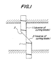
- Fig. 1 shows a main portion of the cutting blades.
- Fig. 2 shows the locus of the main portion of the cutting blades when the difference in circumferential speeds is positive.
- Fig. 3 schematically shows a conventional type drum shear.
- Fig. 4 illustrates a cutting process in which the steel piece is cut under the same circumferential speed.
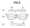
- Figs. 5 (a), (b), (c) illustrate the cutting condition, the joining condition and the rolled condition of a steel piece when cutting according to the conventional method.
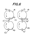
- Fig. 6 shows a drum shear for cutting a steel piece according to the present invention.
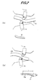
- Figs. 7 (a), (b) illustrate the cutting condition when cutting a steel piece according to the conventional method.
- Figs. 8 (a), (b) illustrate the cutting condition when cutting a steel piece according to the present invention.
- Figs. 9 (a), (b) illustrate the warping condition and the joining condition when cutting a steel piece according to the present invention.
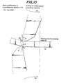
- Fig. 10 illustrates a cutting process in which the steel piece is cut with a positive difference in circumferential speeds.
- Fig. 11 illustrates a cutting process in which the steel piece is cut with a negative difference in circumferential speeds.
- Fig. 12 illustrates the relationship between the difference in circumferential speeds and the warp (curvature).
- Fig. 13 illustrates the amount of the projection at the end of the steel piece after cutting.
- Fig. 14 illustrates the relationship between the difference in circumferential speeds and the amount of the projection at the end of the steel piece.
- Figs. 15 (a), (b) show for comparison the shape of the end of the steel piece in the case where the steel piece is cut under the same circumferential speed and the shape of the end of the steel piece in the case where the steel piece is cut under different circumferential speeds.
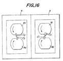
- Fig. 16 shows another example of the structure of a drum shear suitable for carrying out the present invention.
- Fig. 17 shows an arrangement of a continuous hot finish rolling equipment.
- Fig. 18 schematically shows a drum shear used in the embodiment of inventive example 1.
- Fig. 1 illustrates the main part of a pair of cutting blades in the cutting process, wherein reference numeral 1 designates the obverse of the cutting blade and reference numeral 2 designates the reverse of the cutting blade.
- Fig. 2 shows the tip of the cutting blade disposed on a pair of upper and lower rotating drums of a drum shear, illustrating the locus of the cutting blades when the rate of the difference in circumferential speeds is positive.
- a cutting blade is disposed over the steel piece and rotated with the reverse of the cutting blade facing forward, while another cutting blade is disposed under the steel piece and rotated with the obverse of the cutting blade facing forward.
- These cutting blades are rotated at the same speed (same circumferential speed) so as to cut the trailing end of the preceding steel piece and the leading end of the succeeding steel piece, respectively (Fig. 7 (a), (b)).
- the cutting condition just after the cutting blades bite the steel piece when they cut it is shown in Fig.
- an allowable amount of the displacement d is designed to be not more than about 10 % of the finish gauge, although it may slightly fluctuate depending upon the thickness of the finish gauge.
- the trailing end of the preceding steel piece and the leading end of the succeeding steel piece are cut individually by two pairs of cutting blades, respectively.
- one pair of the cutting blades has the obverses of the blades oriented in opposite directions at the obverse and the reverse sides of the steel piece.
- Another pair of the cutting blades has the obverses of the blades oriented in opposite directions relative to the former pair of cutting blades. Accordingly, the warping direction of the preceding steel piece is the same as the warping direction of the succeeding steel piece. It is thus possible to significantly reduce the displacement at the joined portion.
- Fig. 6 shows a drum type crop shear which is suitable for carrying out the present invention.
- the illustrated crop shear comprises drums d 1 , d 2 disposed on the obverse side and the reverse side of the steel piece, and cutting blades c 1 , c 1' , c 2 , c 2 , which are fixedly secured to the surfaces of these drums.
- the cutting blade c 1 is paired with the cutting blade c 1'
- the cutting blade c 2 is paired with the cutting blade c 2' .
- the obverses of the cutting blades are opposite in direction for each pair of cutting blades and the obverses of the blades of the pairs of cutting blades c 1 and c 1' and the obverses of the blades of the pairs of cutting blades c 2 and c 2' are also opposite in direction.
- the drums d 1 , d 2 are rotatably secured to drum chucks disposed in a housing (not shown) , and the upper drums rotate counterclockwise and the lower drums rotate clockwise so that the preceding steel piece and the succeeding steel piece are cut by a pair of cutting blades c 1 , c 1' fixedly secured to the surfaces of the drums d 1 , d 2 and by the other pair of cutting blades c 2 , c 2' fixedly secured to the surfaces of the drums d 1 , d 2' respectively, while they are transferred from the left side to the right side in the drawing.
- Figs. 7 (a), (b) For comparison, the cutting condition when cutting the steel piece by a conventional drum shear is shown in Figs. 7 (a), (b) and the cutting condition when cutting the steel piece in accordance with the present invention is shown in Figs. 8 (a), (b).
- the above described method may not sufficiently reduce the warp amount and there may be fluctuations in the warp amount, thereby leaving certain problem in terms of the operational reliability. Accordingly, the inventors conducted thorough investigations seeking for solutions of such a problem. Such investigations led the inventors to a recognition that, by performing the cutting at differential circumferential speeds, not only the warp amount but also the fluctuations of the warp amount can be reduced.
- Fig. 10 shows the cutting condition just after the cutting blades bite into the steel piece when the steel piece is cut under the conditions of different circumferential speeds (the difference in the circumferential speeds is 5 %) in which the traveling speed V f of the cutting blade which rotates with the reverse of the cutting blade facing forward is larger than the traveling speed V b of the cutting blade which rotates with the obverse of the cutting blade facing forward.
- the bending moment M when cutting with a positive difference in circumferential speeds (5 %) is smaller than the bending moment M when cutting at an equal circumferential speed as shown in Fig. 4.
- the traveling speed V f of the cutting blade which rotates with the reverse of the cutting blade facing forward is larger than the traveling speed of the other cutting blade.
- the vertical plane including the tip O of the cutting blade is positioned on the reverse side of the other cutting blade and the vertical plane including the tip Q of the cutting blade is positioned on the reverse side of the other cutting blade and, therefore, the contact planes OP and QR of the cutting blades overlap each other (zone indicated by broken lines). Accordingly, the warp amount when the difference in circumferential speeds is positive is very small.
- the bending moment M in the case of cutting at a negative difference in circumferential speeds is different from the case of cutting with a positive difference in circumferential speeds, in that it is larger than the bending moment M in the case of cutting under the conditions shown in Fig. 4.
- Fig. 11 shows the cutting condition just after the cutting blades bite into the steel piece when the steel piece is cut under the conditions of a negative difference in circumferential speeds (the rate of the difference in circumferential speeds is -5 %) in which the traveling speed V f of the cutting blade which rotates with the reverse of the cutting blade facing forward is smaller than the traveling speed V b of the cutting blade which rotates with the obverse of the cutting blade facing forward.
- the cutting condition in the case of the negative difference in circumferential speeds (-5 %) is different from the cutting condition in the case of the positive difference in circumferential speeds and the traveling speed V f of the cutting blade which rotates with the reverse of the cutting blade facing forward is smaller than the traveling speed of the other cutting blade. Therefore, as shown in Fig.
- the vertical plane including the tip O of the cutting blade is positioned on the obverse side of one cutting blade, and the vertical plane including the tip Q of the cutting blade is positioned on the obverse side of the other cutting blade and the contact plane OP of the cutting blade is spaced from the contact plane QR of the cutting blade by the zone represented by the broken lines.
- the degree of warping is thus larger in the case of the negative difference in circumferential speeds than in the case of the same circumferential speed.
- the cutting blade which rotates with the reverse of the cutting blade facing forward is located under the steel piece, and the cutting blade which rotates with the obverse of the cutting blade facing forward is located above the steel piece.
- the traveling speed of the former cutting blade is made larger than the traveling speed of the latter cutting blade, so as to reduce the warp amount according to the cutting method of the present invention.
- the relationship between the difference in the circumferential speeds and the warp amount (curvature) when cutting the steel pieces so that the trailing end of the preceding steel piece and the leading end of the succeeding steel piece warp upward, respectively, is shown in Fig. 12.
- the difference in circumferential speeds is less than 5 %.
- the larger the difference in the circumferential speeds the smaller the warp amount of the steel piece.
- the amount of projection at the end of the steel piece shown in Fig. 13 i.e., the length from the end plane to the maximum projecting end in the supposed rectangle which is equal to the same area of the cut end
- the allowable amount of projection is about 5 mm.
- the difference in the circumferential speeds is set at 2 - 3 %, the warp amount can be made smaller and worse shape at the joined plane can be prevented.
- the warp of the succeeding steel piece tends to be larger than the warp of the preceding steel piece, assuming that the preceding steel piece and the succeeding steel piece are cut at different circumferential speeds, it is advantageous that the difference in the circumferential speeds when cutting the succeeding steel piece is made larger than the difference in circumferential speeds when cutting the preceding steel piece, in order to reduce the difference of warp in both cases.
- Cutting at different circumferential speeds is realized by controlling the rotating speed of the rotating drum or by adjusting at least one of the height of the cutting blades disposed on the upper and lower rotating drums and the diameter of the drums.
- Fig. 16 shows another example of the structure of a drum-type crop shear suitable for carrying out the present invention.
- This crop shear is disposed on the obverse side and the reverse side of the steel piece, and comprises drums d 1 , d 2 for cutting the trailing end of the preceding steel piece, cutting blades c 1 , c 1' fixedly secured to the surfaces of these drums, drums d 3 , d 4 for cutting the leading end of the succeeding steel piece, and cutting blades c 2 , c 2' fixedly secured to the surfaces of these drums.
- the obverses of the cutting blades are oriented opposite in direction for each pair of cutting blades and the obverses of the blades of the pairs of cutting blades c 1 , c 1' are oriented opposite in direction to the obverses of the blades of the pairs of cutting blades c 2 , c 2' .
- Reference numerals 3, 4 in Fig. 16 designate housings for accommodating the drums d 1 , d 2 and d 3 , d 4 which are rotatably mounted on the drum chucks in the housings 3, 4 so that the steel piece is cut by the cutting blades while it is transferred from the left side to the right side in the drawing.
- the drum shear makes it possible to freely determine the timing of the cutting of the trailing end of the preceding steel piece and the timing of the cutting of the leading end of the following steel piece by the drums d 1 , d 2 and d 3 , d 4 , respectively. Therefore, the drum shear is particularly advantageous in that the time interval required for cutting can be reduced.
- Fig. 17 shows one example of a continuous hot rolling equipment for steel pieces, which is provided with a cutting device having a structure as shown in Fig. 6.
- reference numeral 5 designates a roughing mill
- reference numeral 6 designates the cutting device for cutting the ends of the preceding steel piece s 1 and the succeeding steel piece s 2
- Reference numeral 7 designates a joining device for heating the cut ends of the steel pieces to raise their temperatures by high-frequency induction heating and joining both steel pieces by pressing them during or after heating
- reference numeral 8 designates a scale breaker
- reference numeral 9 designates a finishing mill train for continuously hot finish rolling the joined steel pieces.
- the high-frequency heating means of the joining device 7 comprises a transverse-type induction heating coil which has a pair of upper and lower magnetic poles sandwiching the steel pieces in their thickness direction and is adapted to apply an alternate magnetic field between the magnetic poles to heat the steel pieces and raise the temperature thereof.
- a clamp which comprises jaw members for clamping the preceding steel piece and the succeeding steel piece and which project towards the ends of the steel pieces.
- each of the jaw members prefferably be provided with cutout portions which are cut out like a comb at predetermined intervals along the width direction of the steel pieces in the region through which the magnetic flux passes, or additionally with an insulating material covering the steel pieces.
- sheet bars (steel grade: low carbon steel) of 1200 mm in width, 30 mm in thickness were cut, heated and pressed against each other and thereby joined in the following manner. The joined sheet bars were then rolled to a finish gauge of 0.8 - 5 mm and the rolled plate was checked for breakage during rolling.
- a preceding sheet bar and a succeeding sheet bar were cut by a drum shear rotating at the same circumferential speed and as shown in Fig. 3 (the warp condition of the preceding sheet bar - radius of curvature r: about 2000 mm, warp amount d: about 30 mm, warp length L: about 400 mm; the warp condition of the succeeding sheet bar - radius of curvature r: about 1000 mm, warp amount d: about 50 mm, warp length L: about 600 mm, see Fig. 7).
- the cut portions were then heated by a joining device for about 10 seconds (high-frequency induction heating, heating condition: output 1000 Hz, rate of heating 100 °C/ sec) to melt the surfaces to be joined and then the sheet bars were pressed against each other and thereby joined (in this case, pressing force: 75 tonf, displacement amount: about 5 - 8 mm).
- the joined sheet bars were then supplied to a finish rolling mill train via a scale breaker (the inter-stand tension of the front stands was set at 0.5 - 1 kgf/mm 2 and that of the rear stands was set at 1 - 1.5 kgf/mm 2 , reduction in thickness of No. 1 - 3 stands: 30 - 50 %, reduction in thickness of No. 4 - 7 stands: 15 - 30 %).
- a preceding sheet bar and a succeeding sheet bar were cut by a drum shear as shown in Fig. 18.
- the warp condition of the preceding sheet bar was upward warp, curvature 0.4 m -1 (radius of curvature 2500 mm), warp amount 25 mm, amount of projection 4 mm; the warp condition of the succeeding sheet bar was upward warp, curvature 0.7 m -1 (radius of curvature 1400 mm), warp amount 30 mm, projection amount 4 mm.
- the cut portions were then heated by a joining device for about 10 seconds (high-frequency induction heating, the heating condition was the same as that of Comparative Example 1) to melt the surface to be joined and then both sheet bars were pressed against each other and thereby joined (in this case, pressing force: 75 tonf, displacement amount: about 0 - 1 mm).
- the present invention can be applied to the case in which the sheet bar warps downward and the warp amount is made small when the sheet bar is cut.
Landscapes
- Engineering & Computer Science (AREA)
- Mechanical Engineering (AREA)
- Metal Rolling (AREA)
- Pressure Welding/Diffusion-Bonding (AREA)
Description
- The present invention relates to a method for joining and continuously hot rolling several to dozens of steel pieces, such as sheet bars, slabs, billets, blooms or the like.
- In a batch type hot rolling line in which a steel piece is individually heated and rolled by a roughing mill and a finishing mill to make a steel sheet of a desired thickness, a line stop tends to occur because the rolled material does not successfully bite into a gap defined by the upper and lower rolls and faulty shapes of the leading and the trailing ends of the rolled material will considerably lower the product yield.
- Therefore, an improved rolling method (endless rolling method) has been adopted in recent years in which the trailing end of a steel piece to be rolled is joined to the leading end of the succeeding steel piece to be rolled before the finish rolling and the resulting steel piece is continuously supplied to a hot rolling line.
- In this respect, reference may be had to JP-A-58-122,109 which describes a method wherein the trailing end of a preceding steel piece is butt-joined to the leading end of a succeeding steel piece over the entire area of the end plane thereof, before they are rolled. Also, JP-A- 4-89,120 describes a method in which the trailing end of a preceding steel piece is arranged against the leading end of a succeeding steel piece with a gap on the entry side of a hot finishing mill equipment and in this area an alternate magnetic field is applied to the steel pieces in their thickness direction to heat them and raise the temperatures thereof by induction heating and then both steel pieces are joined by pressing.
- In such continuous hot rolling of steel pieces, a cutting step is added as a preparatory step for the joining process, in which defective portions at the leading and the trailing ends of the steel piece are cut by a crop shear, drum shear or the like. In the cutting step, however, there may be instances wherein the leading end and/or the trailing end of the steel piece tend to warp upward or downward. As a result, the steel pieces are joined with an upward or downward displacement (hereinafter referred to as "displacement"), as they are pressed against each other.
- In this respect, the reason why the end of the steel piece warps in the cutting step is that a moment is produced in the cut plane when the end of the steel piece is cut by a crop shear. Usually, the preceding steel piece and the succeeding steel piece are cut by the same cutting blade so that they warp in opposite directions. If the steel pieces are heated to raise their temperatures and pressed in such a condition, they tend to further warp upward and downward to substantially decrease the effective joint area. This tends to cause the demerit that the steel pieces are broken in the following finish rolling process at the joined portion. In particular, when a transverse-type induction heating is used as heating means and an alternate magnetic field is applied to the steel pieces in their thickness direction for heating them by induction heating, due to the requirement for the installation space of the heating coil, a clamp for sandwiching the steel pieces must be used at a location which is remote from the ends of the steel pieces. As a result, it has been considered that the influence of the warp in the pressing process of the steel pieces would be more significant by using a clamp having a pair of upper and lower jaw elements which extend toward the ends of the steel pieces.
- Furthermore, JP-A-5-185,111 describes a cutting device having a structure wherein two pairs of upper and lower drums are arranged along the transfer direction of the rolled material and respectively rotated in opposite directions from each other, and cutting blades are mounted on each pair of drums and oriented in opposite directions. Also, JP-A-56-27,719 and JP-A-56-119,311 each describes a cutting technique in which the shear members of a drum type shear are driven at different circumferential speeds to cut the crop end of the steel piece. Moreover, JP-A-7-251,203, in accordance with the preamble of the independent claim, describes a cutting technique in which a flying shear for cutting the end of the steel piece in a parallel surface relation is applied when a plurality of elongate steel pieces for hot rolling are joined by laser welding and are continuously hot rolled. However, even when such a device and/or techniques are applied to the cutting of the steel pieces, it is still impossible to reduce the warping of the steel piece which causes the displacement at the joined portion.
- It is an object of the present invention to provide a method for reducing the displacement at the joined portion of the steel pieces even when a traverse-type high-frequency induction heating is used as heating method, thereby allowing a stable continuous hot rolling to be carried out without defective joining or breakage at the joined portion.
- The inventors have conducted thorough researches and investigations in view of the above-mentioned object and arrived at a novel recognition that it would be highly effective, for accomplishing the object, to make the trailing end of the preceding steel piece and the leading end of the succeeding steel piece warp in the same direction and, in addition, to reduce the warp amount by cutting the ends with a drum shear rotating at different circumferential speeds. The present invention is based on such a recognition.
- According to the present invention, there is provided a continuous hot rolling method for continuously hot finish rolling steel pieces, comprising the steps of transferring a preceding steel piece and a succeeding steel piece in the same direction, cutting the trailing end of the preceding steel piece and the leading end of the succeeding steel piece with a drum shear which comprises an upper drum and a lower drum, having cutting blades on their outer peripheries and which sandwiches the steel pieces between the drums thereof; joining the trailing end of the preceding steel piece and the leading end of the succeeding steel piece to each other; and supplying the joined steel pieces to rolling equipment in which method the trailing end of the preceding steel piece and the leading end of the succeeding steel piece are cut individually by first and second pairs of the cutting blades; wherein the cutting blades of each pair are located at opposite sides of the steel pieces and at the time of cutting the obverses of the blades of the first pair face in opposite directions and the obverses of the blades of the second pair face in opposite directions relative to the blades of the first pair, characterized in that the cutting blades disposed at the obverse side and the cutting blades disposed at the reverse side of the steel pieces have different circumferential speeds such that the travelling speed of the cutting blades rotating with their reverse facing forward is higher than the travelling speed of the cutting blades rotating with their obverse facing forward, and in that the trailing end of the preceding steel piece and the leading end of the succeeding steel piece are joined to each other by heating the cut ends and raising the temperatures thereof by high-frequency induction heating and pressing the cut ends together to butt-join the cut ends.
- It is advantageous for the difference in circumferential speeds at the cutting of the steel piece to be not more than 5 percent.
- In accordance with the present invention, the steel piece may be cut by one drum shear, though it may be cut by two drum shears disposed in tandem along the direction in which the steel piece is transferred.
- Fig. 1 shows a main portion of the cutting blades.
- Fig. 2 shows the locus of the main portion of the cutting blades when the difference in circumferential speeds is positive.
- Fig. 3 schematically shows a conventional type drum shear.
- Fig. 4 illustrates a cutting process in which the steel piece is cut under the same circumferential speed.
- Figs. 5 (a), (b), (c) illustrate the cutting condition, the joining condition and the rolled condition of a steel piece when cutting according to the conventional method.
- Fig. 6 shows a drum shear for cutting a steel piece according to the present invention.
- Figs. 7 (a), (b) illustrate the cutting condition when cutting a steel piece according to the conventional method.
- Figs. 8 (a), (b) illustrate the cutting condition when cutting a steel piece according to the present invention.
- Figs. 9 (a), (b) illustrate the warping condition and the joining condition when cutting a steel piece according to the present invention.
- Fig. 10 illustrates a cutting process in which the steel piece is cut with a positive difference in circumferential speeds.
- Fig. 11 illustrates a cutting process in which the steel piece is cut with a negative difference in circumferential speeds.
- Fig. 12 illustrates the relationship between the difference in circumferential speeds and the warp (curvature).
- Fig. 13 illustrates the amount of the projection at the end of the steel piece after cutting.
- Fig. 14 illustrates the relationship between the difference in circumferential speeds and the amount of the projection at the end of the steel piece.
- Figs. 15 (a), (b) show for comparison the shape of the end of the steel piece in the case where the steel piece is cut under the same circumferential speed and the shape of the end of the steel piece in the case where the steel piece is cut under different circumferential speeds.
- Fig. 16 shows another example of the structure of a drum shear suitable for carrying out the present invention.
- Fig. 17 shows an arrangement of a continuous hot finish rolling equipment.
- Fig. 18 schematically shows a drum shear used in the embodiment of inventive example 1.
- Referring now to the drawings, Fig. 1 illustrates the main part of a pair of cutting blades in the cutting process, wherein
reference numeral 1 designates the obverse of the cutting blade andreference numeral 2 designates the reverse of the cutting blade. In connection with the rate f of the difference in circumferential speeds, Fig. 2 shows the tip of the cutting blade disposed on a pair of upper and lower rotating drums of a drum shear, illustrating the locus of the cutting blades when the rate of the difference in circumferential speeds is positive. The rate of the difference in circumferential speeds is expressed by the following equation: - In the conventional method shown in Fig. 3, a cutting blade is disposed over the steel piece and rotated with the reverse of the cutting blade facing forward, while another cutting blade is disposed under the steel piece and rotated with the obverse of the cutting blade facing forward. These cutting blades are rotated at the same speed (same circumferential speed) so as to cut the trailing end of the preceding steel piece and the leading end of the succeeding steel piece, respectively (Fig. 7 (a), (b)). The cutting condition just after the cutting blades bite the steel piece when they cut it is shown in Fig. 4 (cutting of the trailing end of the preceding steel piece) , wherein the characters O, Q designate the tips of the cutting blades, and planes OP, QR designate the contact surfaces with which the cutting blades come into contact when the cutting blades bite into the steel piece.
- Since the contact planes OP and QR of the cutting blades are at the front and at the rear of the plane OQ in this cutting method, a bending moment M (indicated by arrows in the drawing) centering on the shear plane is produced in the steel piece so that the trailing end of the preceding steel piece S1 warps upward after the cutting. On the other hand, since the bending moment acts on the steel piece in the same direction centering on the shear plane when the leading end of the succeeding steel piece is cut, the leading end of the succeeding steel piece S2 warps downward (see Fig. 7 (b)). Accordingly, the joining condition shown in Fig. 5 (a) is obtained when the preceding steel piece is joined to the succeeding steel piece.
- When the steel pieces warping upward and downward as described above are heated to raise their temperatures and pressed and thereby joined, they exhibit a displacement as shown in Fig. 5(b). The displaced portions overlap the base metal during the finish rolling, as shown in Fig. 5(c), thereby forming a region with a reduced thickness which may cause the rolled plate to be broken during the rolling process. Accordingly, an allowable amount of the displacement d is designed to be not more than about 10 % of the finish gauge, although it may slightly fluctuate depending upon the thickness of the finish gauge.
- According to the present invention, the trailing end of the preceding steel piece and the leading end of the succeeding steel piece are cut individually by two pairs of cutting blades, respectively. In this instance, one pair of the cutting blades has the obverses of the blades oriented in opposite directions at the obverse and the reverse sides of the steel piece. Another pair of the cutting blades has the obverses of the blades oriented in opposite directions relative to the former pair of cutting blades. Accordingly, the warping direction of the preceding steel piece is the same as the warping direction of the succeeding steel piece. It is thus possible to significantly reduce the displacement at the joined portion.
- Fig. 6 shows a drum type crop shear which is suitable for carrying out the present invention. The illustrated crop shear comprises drums d1, d2 disposed on the obverse side and the reverse side of the steel piece, and cutting blades c1, c1', c2 , c2, which are fixedly secured to the surfaces of these drums. The cutting blade c1 is paired with the cutting blade c1', and the cutting blade c2 is paired with the cutting blade c2'. When a pair of cutting blades cuts a steel piece, the obverses of the cutting blades are opposite in direction for each pair of cutting blades and the obverses of the blades of the pairs of cutting blades c1 and c1' and the obverses of the blades of the pairs of cutting blades c2 and c2' are also opposite in direction. In Fig. 6, the drums d1, d2 are rotatably secured to drum chucks disposed in a housing (not shown) , and the upper drums rotate counterclockwise and the lower drums rotate clockwise so that the preceding steel piece and the succeeding steel piece are cut by a pair of cutting blades c1, c1' fixedly secured to the surfaces of the drums d1, d2 and by the other pair of cutting blades c2, c2' fixedly secured to the surfaces of the drums d1, d2' respectively, while they are transferred from the left side to the right side in the drawing.
- For comparison, the cutting condition when cutting the steel piece by a conventional drum shear is shown in Figs. 7 (a), (b) and the cutting condition when cutting the steel piece in accordance with the present invention is shown in Figs. 8 (a), (b).
- In the case where the steel pieces are cut with the same cutting blades as shown in Figs. 7 (a), (b), it is generally difficult to make the warping directions as well as the amount of warp equal when cutting the trailing end of the preceding steel piece and the leading end of the succeeding steel piece. In the case of the cutting process shown in Figs. 8 (a) , (b) , however, it is possible to reduce the amount of warp produced when the steel pieces are cut, hence, to make the displacement smaller by adjusting the clearances of each pair of the cutting blades.
- In the case of cutting the steel piece by a shear shown in Fig. 6 described above, while the cutting blades c1, c1' and c2, c2' can be used for cutting both the preceding steel piece and the succeeding steel piece, it is important to cut them so that they warp in the same direction.
- As described above, when the ends of the preceding steel piece and the succeeding steel piece are cut by the cutting blades c1, c1' and c2, c2' respectively, they tend to warp as shown in Fig. 9 (a) . Accordingly, they are thereafter heated to raise their temperatures and pressed against each other and thereby achieve a satisfactory joining as shown in Fig. 9 (b).
- In this respect, the above described method may not sufficiently reduce the warp amount and there may be fluctuations in the warp amount, thereby leaving certain problem in terms of the operational reliability. Accordingly, the inventors conducted thorough investigations seeking for solutions of such a problem. Such investigations led the inventors to a recognition that, by performing the cutting at differential circumferential speeds, not only the warp amount but also the fluctuations of the warp amount can be reduced.
- For example, the case of cutting the trailing end of the preceding steel piece S1 such that the trailing end of the preceding steel piece S1 warps upward is described with reference to Fig. 10. Fig. 10 shows the cutting condition just after the cutting blades bite into the steel piece when the steel piece is cut under the conditions of different circumferential speeds (the difference in the circumferential speeds is 5 %) in which the traveling speed Vf of the cutting blade which rotates with the reverse of the cutting blade facing forward is larger than the traveling speed Vb of the cutting blade which rotates with the obverse of the cutting blade facing forward. The bending moment M when cutting with a positive difference in circumferential speeds (5 %) is smaller than the bending moment M when cutting at an equal circumferential speed as shown in Fig. 4. This is because the traveling speed Vf of the cutting blade which rotates with the reverse of the cutting blade facing forward is larger than the traveling speed of the other cutting blade. As a result, as shown in Fig. 10, the vertical plane including the tip O of the cutting blade is positioned on the reverse side of the other cutting blade and the vertical plane including the tip Q of the cutting blade is positioned on the reverse side of the other cutting blade and, therefore, the contact planes OP and QR of the cutting blades overlap each other (zone indicated by broken lines). Accordingly, the warp amount when the difference in circumferential speeds is positive is very small.
- On the other hand, the bending moment M in the case of cutting at a negative difference in circumferential speeds is different from the case of cutting with a positive difference in circumferential speeds, in that it is larger than the bending moment M in the case of cutting under the conditions shown in Fig. 4.
- Fig. 11 shows the cutting condition just after the cutting blades bite into the steel piece when the steel piece is cut under the conditions of a negative difference in circumferential speeds (the rate of the difference in circumferential speeds is -5 %) in which the traveling speed Vf of the cutting blade which rotates with the reverse of the cutting blade facing forward is smaller than the traveling speed Vb of the cutting blade which rotates with the obverse of the cutting blade facing forward. The cutting condition in the case of the negative difference in circumferential speeds (-5 %) is different from the cutting condition in the case of the positive difference in circumferential speeds and the traveling speed Vf of the cutting blade which rotates with the reverse of the cutting blade facing forward is smaller than the traveling speed of the other cutting blade. Therefore, as shown in Fig. 11, the vertical plane including the tip O of the cutting blade is positioned on the obverse side of one cutting blade, and the vertical plane including the tip Q of the cutting blade is positioned on the obverse side of the other cutting blade and the contact plane OP of the cutting blade is spaced from the contact plane QR of the cutting blade by the zone represented by the broken lines. The degree of warping is thus larger in the case of the negative difference in circumferential speeds than in the case of the same circumferential speed. The cutting condition when cutting the trailing end of the preceding steel piece has been described above. In the case of cutting the leading end of the succeeding steel piece, it is recommended that the cutting blade which rotates with the reverse of the cutting blade facing forward is located under the steel piece, and the cutting blade which rotates with the obverse of the cutting blade facing forward is located above the steel piece. Also the traveling speed of the former cutting blade is made larger than the traveling speed of the latter cutting blade, so as to reduce the warp amount according to the cutting method of the present invention.
- The relationship between the difference in the circumferential speeds and the warp amount (curvature) when cutting the steel pieces so that the trailing end of the preceding steel piece and the leading end of the succeeding steel piece warp upward, respectively, is shown in Fig. 12. The difference in the circumferential speed f is calculated by the equation, as in the case described above, f = (Vf - Vb) / Vb x 100 %, where Vf is the traveling speed of the cutting blade which rotates with the reverse of the cutting blade facing forward, and Vb is the traveling speed of the cutting blade which rotates with the obverse of the cutting blade facing forward.
- It is advantageous for the difference in circumferential speeds to be less than 5 %. As shown in Fig. 12, the larger the difference in the circumferential speeds , the smaller the warp amount of the steel piece. However when the difference in the circumferential speeds is more than 5 %, the amount of projection at the end of the steel piece shown in Fig. 13 (i.e., the length from the end plane to the maximum projecting end in the supposed rectangle which is equal to the same area of the cut end) becomes large as shown in Fig. 14. Thus there may be produced defective joining when a transverse-type high-frequency induction heating process is used, in which an alternate magnetic field is applied at the end of the steel piece in the thickness direction to heat the steel piece (the allowable amount of projection is about 5 mm). In particular, when the difference in the circumferential speeds is set at 2 - 3 %, the warp amount can be made smaller and worse shape at the joined plane can be prevented.
- Since the warp of the succeeding steel piece tends to be larger than the warp of the preceding steel piece, assuming that the preceding steel piece and the succeeding steel piece are cut at different circumferential speeds, it is advantageous that the difference in the circumferential speeds when cutting the succeeding steel piece is made larger than the difference in circumferential speeds when cutting the preceding steel piece, in order to reduce the difference of warp in both cases.
- The shape of the end of the steel piece when the steel piece is cut by the drums rotating at the same circumferential speed and the shape of the end of the steel piece when the steel piece is cut by the drums rotating at different circumferential speeds are shown in Fig. 15 (a), (b) for comparison (the warp is not shown in the drawing).
- Cutting at different circumferential speeds is realized by controlling the rotating speed of the rotating drum or by adjusting at least one of the height of the cutting blades disposed on the upper and lower rotating drums and the diameter of the drums.
- Fig. 16 shows another example of the structure of a drum-type crop shear suitable for carrying out the present invention. This crop shear is disposed on the obverse side and the reverse side of the steel piece, and comprises drums d1, d2 for cutting the trailing end of the preceding steel piece, cutting blades c1, c1' fixedly secured to the surfaces of these drums, drums d3, d4 for cutting the leading end of the succeeding steel piece, and cutting blades c2, c2' fixedly secured to the surfaces of these drums.
- When the pairs of cutting blades c1, c1' and c2, c2' cut the steel piece, the obverses of the cutting blades are oriented opposite in direction for each pair of cutting blades and the obverses of the blades of the pairs of cutting blades c1, c1' are oriented opposite in direction to the obverses of the blades of the pairs of cutting blades c2, c2'.
-
Reference numerals housings - When the ends of the preceding steel piece and the succeeding steel piece are cut by the cutting blades c1, c1' and c2, c2' at different circumferential speeds, respectively, the ends of the steel piece tend to warp in the same direction and the warp amount is very small. Accordingly, when the ends of the steel pieces are heated to raise their temperatures and pressed against each other there is a minimized displacement, thereby preventing the rolled plate from being broken during the rolling.
- Moreover, when cutting the steel piece with the shear shown in Fig. 6 and described above, it is necessary to make a time allowance for synchronizing the cutting portion of the succeeding steel piece to the position of the cutting blades of the drum shear before cutting the leading end of the succeeding steel piece after cutting the trailing end of the preceding steel piece. In this connection, as shown in Fig. 16, the drum shear makes it possible to freely determine the timing of the cutting of the trailing end of the preceding steel piece and the timing of the cutting of the leading end of the following steel piece by the drums d1, d2 and d3, d4, respectively. Therefore, the drum shear is particularly advantageous in that the time interval required for cutting can be reduced.
- Fig. 17 shows one example of a continuous hot rolling equipment for steel pieces, which is provided with a cutting device having a structure as shown in Fig. 6.
- In the drawing,
reference numeral 5 designates a roughing mill, andreference numeral 6 designates the cutting device for cutting the ends of the preceding steel piece s1 and the succeeding steel piece s2.Reference numeral 7 designates a joining device for heating the cut ends of the steel pieces to raise their temperatures by high-frequency induction heating and joining both steel pieces by pressing them during or after heating,reference numeral 8 designates a scale breaker, andreference numeral 9 designates a finishing mill train for continuously hot finish rolling the joined steel pieces. - In the equipment having the above-mentioned structure, in particular, the high-frequency heating means of the joining
device 7 comprises a transverse-type induction heating coil which has a pair of upper and lower magnetic poles sandwiching the steel pieces in their thickness direction and is adapted to apply an alternate magnetic field between the magnetic poles to heat the steel pieces and raise the temperature thereof. - When such an induction heating coil is adopted, as described above, it may be difficult to sandwich and press the ends of the steel pieces with a clamp due to the installation space required for the induction heating coil and thus a clamp is used which comprises jaw members for clamping the preceding steel piece and the succeeding steel piece and which project towards the ends of the steel pieces.
- In particular, it is highly advantageous for each of the jaw members to be provided with cutout portions which are cut out like a comb at predetermined intervals along the width direction of the steel pieces in the region through which the magnetic flux passes, or additionally with an insulating material covering the steel pieces.
- By using the hot rolling equipment shown in Fig. 17, sheet bars (steel grade: low carbon steel) of 1200 mm in width, 30 mm in thickness were cut, heated and pressed against each other and thereby joined in the following manner. The joined sheet bars were then rolled to a finish gauge of 0.8 - 5 mm and the rolled plate was checked for breakage during rolling.
- A preceding sheet bar and a succeeding sheet bar were cut by a drum shear rotating at the same circumferential speed and as shown in Fig. 3 (the warp condition of the preceding sheet bar - radius of curvature r: about 2000 mm, warp amount d: about 30 mm, warp length L: about 400 mm; the warp condition of the succeeding sheet bar - radius of curvature r: about 1000 mm, warp amount d: about 50 mm, warp length L: about 600 mm, see Fig. 7). The cut portions were then heated by a joining device for about 10 seconds (high-frequency induction heating, heating condition: output 1000 Hz, rate of heating 100 °C/ sec) to melt the surfaces to be joined and then the sheet bars were pressed against each other and thereby joined (in this case, pressing force: 75 tonf, displacement amount: about 5 - 8 mm). The joined sheet bars were then supplied to a finish rolling mill train via a scale breaker (the inter-stand tension of the front stands was set at 0.5 - 1 kgf/mm2 and that of the rear stands was set at 1 - 1.5 kgf/mm2, reduction in thickness of No. 1 - 3 stands: 30 - 50 %, reduction in thickness of No. 4 - 7 stands: 15 - 30 %). As a result, it was found that the rolled plates having a finish gauge of less than 2 mm were frequently broken at the joined portion thereof between the rear rolling mill stands and, in particular, for rolled plate of 1.5 mm finish gauge, the ratio of the rolled plates passing through the rolling mills without breakage was less than 90 %.
- A preceding sheet bar and a succeeding sheet bar were cut by a drum shear as shown in Fig. 18. The rotating angular speed of the upper drum was the same as that of the lower drum; the radii r of the cutting blades of the upper drum and the lower drum were in the relationship of rf1 / rb1 = 1.02 (the rate of difference in circumferential speeds was 2 %) for cutting the preceding sheet bar; and the radii r were in the relationship of rf2 / rb2 = 1.04 (the rate of difference in circumferential speeds was 4 %) for cutting the succeeding sheet bar. The warp condition of the preceding sheet bar was upward warp, curvature 0.4 m-1 (radius of curvature 2500 mm), warp amount 25 mm, amount of
projection 4 mm; the warp condition of the succeeding sheet bar was upward warp, curvature 0.7 m-1 (radius of curvature 1400 mm), warp amount 30 mm, projection amount 4 mm. The cut portions were then heated by a joining device for about 10 seconds (high-frequency induction heating, the heating condition was the same as that of Comparative Example 1) to melt the surface to be joined and then both sheet bars were pressed against each other and thereby joined (in this case, pressing force: 75 tonf, displacement amount: about 0 - 1 mm). The sheet bars were then rolled to a finish gauge of 0.8 - 5 mm (rolling condition was the same as that of Comparative Example 1). As a result, one hundred sheet bars of 0. 8 mm finish gauge were rolled without any breakage during rolling and thus it was verified that continuous hot rolling was stably implemented by the method according to the invention. - Although the above description relates to the case in which the sheet bar warped upward and the warp amount was made small when the sheet bar was cut, needless to say the present invention can be applied to the case in which the sheet bar warps downward and the warp amount is made small when the sheet bar is cut.
- Since the displacement produced in the case of joining steel pieces by using transverse-type high-frequency induction heating can be made extremely small in accordance with the present, continuous hot rolling can be stably carried out without breakage.
Claims (6)
- A continuous hot rolling method for continuously hot finish rolling steel pieces, comprising the steps of transferring a preceding steel piece and a succeeding steel piece in the same direction, cutting the trailing end (S1) of the preceding steel piece and the leading end (S2) of the succeeding steel piece with a drum shear (6) which comprises an upper drum (d1)(d3) and a lower drum (d2)(d4), having cutting blades (c) on their outer peripheries and which sandwiches the steel pieces between the drums thereof; joining the trailing end of the preceding steel piece and the leading end of the succeeding steel piece to each other; and supplying the joined steel pieces to rolling equipment (9) in which method the trailing end of the preceding steel piece and the leading end of the succeeding steel piece are cut individually by first and second pairs (C1,C2) of the cutting blades; wherein the cutting blades of each pair (C1,C1') (C2,C2') are located at opposite sides of the steel pieces and at the time of cutting the obverses (1) of the blades (C1,C1') of the first pair face in opposite directions and the obverses (1) of the blades (C2,C2') of the second pair face in opposite directions relative to the blades (C1,C1') of the first pair, characterized in that the cutting blades (C1,C2) disposed at the obverse side and the cutting blades (C1',C2') disposed at the reverse side of the steel pieces have different circumferential speeds such that the travelling speed of the cutting blades (C1,C2') rotating with their reverse facing forward is higher than the travelling speed of the cutting blades (C2,C1') rotating with their obverse facing forward, and in that the trailing end of the preceding steel piece and the leading end of the succeeding steel piece are joined to each other by heating the cut ends and raising the temperatures thereof by high-frequency induction heating and pressing the cut ends together (7) to butt-join the cut ends.
- A continuous hot rolling method for continuously hot finish rolling steel pieces as claimed in claim 1, in which the difference in circumferential speeds is not more than 5%.
- A continuous hot rolling method for continuously hot finish rolling steel pieces as claimed in claim 1 or 2, in which the first and second pairs of cutting blades are mounted on two drum shears (3,4) disposed in tandem along the transfer direction.
- A continuous hot rolling method for continuously hot finish rolling steel pieces as claimed in claim 1 or 2, in which the first and second pairs of cutting blades are mounted on one drum shear.
- A continuous hot rolling method for continuously hot finish rolling steel pieces as claimed in any preceding claim wherein the different circumferential speeds are achieved by adjusting the height of the cutting blades with respect to the drums and/or the diameter of the drums.
- A continuous hot rolling method for continuously hot finish rolling steel pieces as claimed in any one of claims 1 to 3 wherein the different circumferential speeds are achieved by controlling the rotating speed of the drums.
Applications Claiming Priority (4)
| Application Number | Priority Date | Filing Date | Title |
|---|---|---|---|
| JP177398/95 | 1995-07-13 | ||
| JP17739895 | 1995-07-13 | ||
| JP17739895 | 1995-07-13 | ||
| PCT/JP1996/000034 WO1997002907A1 (en) | 1995-07-13 | 1996-01-12 | Method of continuous hot rolling of billet |
Publications (3)
| Publication Number | Publication Date |
|---|---|
| EP0782890A1 EP0782890A1 (en) | 1997-07-09 |
| EP0782890A4 EP0782890A4 (en) | 1999-07-14 |
| EP0782890B1 true EP0782890B1 (en) | 2002-11-27 |
Family
ID=16030237
Family Applications (1)
| Application Number | Title | Priority Date | Filing Date |
|---|---|---|---|
| EP96900437A Expired - Lifetime EP0782890B1 (en) | 1995-07-13 | 1996-01-12 | Method of continuous hot rolling of billet |
Country Status (7)
| Country | Link |
|---|---|
| US (1) | US5957368A (en) |
| EP (1) | EP0782890B1 (en) |
| KR (1) | KR100205689B1 (en) |
| CN (1) | CN1059135C (en) |
| CA (1) | CA2199872C (en) |
| DE (1) | DE69625030T2 (en) |
| WO (1) | WO1997002907A1 (en) |
Cited By (1)
| Publication number | Priority date | Publication date | Assignee | Title |
|---|---|---|---|---|
| CN105834514A (en) * | 2015-01-12 | 2016-08-10 | 宝山钢铁股份有限公司 | Flying shear great circular arc blade and polishing method |
Families Citing this family (8)
| Publication number | Priority date | Publication date | Assignee | Title |
|---|---|---|---|---|
| JP2004516060A (en) * | 2000-12-21 | 2004-06-03 | プレシメッド エス.アー. | Holder for surgical reamer |
| US7140426B2 (en) | 2003-08-29 | 2006-11-28 | Plascore, Inc. | Radiant panel |
| WO2007124872A1 (en) * | 2006-04-27 | 2007-11-08 | Sms Demag Ag | Apparatus for the connection of strips |
| JP5999265B2 (en) * | 2013-08-02 | 2016-09-28 | 東芝三菱電機産業システム株式会社 | Energy-saving operation recommendation system |
| CN111215689B (en) * | 2019-12-06 | 2021-03-19 | 中冶华天南京工程技术有限公司 | Bar shearing method of multi-length flying shear mechanism |
| GB202213171D0 (en) | 2022-09-08 | 2022-10-26 | Pong David Teng | Flash welding for billets with "down cut" billet ends |
| JP2024139504A (en) * | 2023-03-27 | 2024-10-09 | 株式会社デンソー | Cutting device |
| EP4599966A1 (en) * | 2024-02-12 | 2025-08-13 | Primetals Technologies Austria GmbH | Rotary shears with extended use range |
Family Cites Families (15)
| Publication number | Priority date | Publication date | Assignee | Title |
|---|---|---|---|---|
| US3895549A (en) * | 1973-06-13 | 1975-07-22 | Nippon Steel Corp | Apparatus for shearing of steel strip end in hot finish rolling |
| DE2341255C2 (en) * | 1973-08-16 | 1982-08-26 | Hugo Miebach Gmbh, 4600 Dortmund | Flash butt welding machine for joining bands |
| JPS5627719A (en) * | 1979-08-08 | 1981-03-18 | Mitsubishi Heavy Ind Ltd | Drum type shear |
| JPS56119311A (en) * | 1980-02-20 | 1981-09-18 | Mitsubishi Heavy Ind Ltd | Drum shear |
| JPS58122109A (en) * | 1982-01-13 | 1983-07-20 | Kawasaki Steel Corp | Method for connecting material to be hot-rolled |
| JPS62234679A (en) * | 1986-04-04 | 1987-10-14 | Meidensha Electric Mfg Co Ltd | Butt welding method for plate and equipment therefor |
| DE3909620A1 (en) * | 1989-03-23 | 1990-09-27 | Bernd Buedenbender | Butt-welding process for plates |
| JPH0692001B2 (en) * | 1990-08-02 | 1994-11-16 | 川崎製鉄株式会社 | Billet joining device |
| CN1022385C (en) * | 1990-10-15 | 1993-10-13 | 三菱重工业株式会社 | Connecting method for rolling stocks |
| JP3084860B2 (en) * | 1991-12-06 | 2000-09-04 | 石川島播磨重工業株式会社 | Rolled material cutting equipment |
| JPH0639405A (en) * | 1992-07-27 | 1994-02-15 | Kawasaki Steel Corp | Method for joining billet in continuous hot rolling |
| JP3200220B2 (en) * | 1993-02-10 | 2001-08-20 | 川崎製鉄株式会社 | Method of joining billets in continuous hot rolling |
| JPH0724627A (en) * | 1993-07-08 | 1995-01-27 | Kawasaki Steel Corp | Drum-shaped shear |
| JPH0780510A (en) * | 1993-09-17 | 1995-03-28 | Ishikawajima Harima Heavy Ind Co Ltd | Rotary cutting device |
| JP3331508B2 (en) * | 1994-03-16 | 2002-10-07 | 新日本製鐵株式会社 | Continuous hot rolling equipment for steel and flying crop shear used therefor |
-
1996
- 1996-01-12 CA CA002199872A patent/CA2199872C/en not_active Expired - Fee Related
- 1996-01-12 KR KR1019970701616A patent/KR100205689B1/en not_active Expired - Fee Related
- 1996-01-12 EP EP96900437A patent/EP0782890B1/en not_active Expired - Lifetime
- 1996-01-12 US US08/793,845 patent/US5957368A/en not_active Expired - Fee Related
- 1996-01-12 WO PCT/JP1996/000034 patent/WO1997002907A1/en not_active Ceased
- 1996-01-12 CN CN96191025A patent/CN1059135C/en not_active Expired - Fee Related
- 1996-01-12 DE DE69625030T patent/DE69625030T2/en not_active Expired - Fee Related
Cited By (1)
| Publication number | Priority date | Publication date | Assignee | Title |
|---|---|---|---|---|
| CN105834514A (en) * | 2015-01-12 | 2016-08-10 | 宝山钢铁股份有限公司 | Flying shear great circular arc blade and polishing method |
Also Published As
| Publication number | Publication date |
|---|---|
| DE69625030D1 (en) | 2003-01-09 |
| KR100205689B1 (en) | 1999-07-01 |
| EP0782890A1 (en) | 1997-07-09 |
| CA2199872A1 (en) | 1997-01-30 |
| EP0782890A4 (en) | 1999-07-14 |
| CN1059135C (en) | 2000-12-06 |
| US5957368A (en) | 1999-09-28 |
| DE69625030T2 (en) | 2003-07-31 |
| CN1164835A (en) | 1997-11-12 |
| CA2199872C (en) | 2000-04-18 |
| WO1997002907A1 (en) | 1997-01-30 |
Similar Documents
| Publication | Publication Date | Title |
|---|---|---|
| EP0661112B1 (en) | Method and apparatus for continuous hot rolling of metal pieces | |
| US5957368A (en) | Method of continuously hot rolling steel pieces | |
| JPS61259804A (en) | Method and device for rolling band material before finishingto hot wide band material | |
| US5292052A (en) | Continous hot rolling method and joining method of sheet bar | |
| US4347724A (en) | Method and knives for shearing metal bar | |
| EP0469483A2 (en) | Process for coiler drum alternation in incessant hot rolling and apparatus therefor | |
| EP0528385B1 (en) | Method of continuously hot-rolling sheet bars | |
| JPS6320653B2 (en) | ||
| JPH0985310A (en) | Continuous hot rolling method for billet | |
| JP2708313B2 (en) | Method and apparatus for joining hot rolled materials | |
| JPH0724507A (en) | Joining method of steel slab in continuous hot rolling | |
| JP2626642B2 (en) | Continuous hot rolling of billets | |
| JP3020635B2 (en) | Method of joining billets in hot rolling | |
| JP3126875B2 (en) | Continuous hot rolling of billets | |
| JPH0729123B2 (en) | Joining method of billets in hot rolling | |
| JPH0489112A (en) | Continuous hot rolling method for billet | |
| JP3105709B2 (en) | Method of joining billets in continuous hot rolling | |
| JP3126745B2 (en) | Method of joining billets in hot rolling | |
| JP2971711B2 (en) | Method of joining billets in continuous hot rolling | |
| JP3362076B2 (en) | Continuous hot rolling of billets | |
| JPH07241601A (en) | Continuous hot rolling equipment for billets | |
| JPH0724503A (en) | Equipment line for joining steel billets | |
| JPH0489120A (en) | Device for joining steel ingot | |
| JP2854428B2 (en) | Continuous hot rolling of billets | |
| JP3520148B2 (en) | Continuous hot rolling method |
Legal Events
| Date | Code | Title | Description |
|---|---|---|---|
| PUAI | Public reference made under article 153(3) epc to a published international application that has entered the european phase |
Free format text: ORIGINAL CODE: 0009012 |
|
| 17P | Request for examination filed |
Effective date: 19970408 |
|
| AK | Designated contracting states |
Kind code of ref document: A1 Designated state(s): DE FR GB |
|
| A4 | Supplementary search report drawn up and despatched |
Effective date: 19990528 |
|
| AK | Designated contracting states |
Kind code of ref document: A4 Designated state(s): DE FR GB |
|
| RIC1 | Information provided on ipc code assigned before grant |
Free format text: 6B 21B 15/00 A, 6B 23D 15/00 B, 6B 23D 25/12 B |
|
| 17Q | First examination report despatched |
Effective date: 20011005 |
|
| GRAG | Despatch of communication of intention to grant |
Free format text: ORIGINAL CODE: EPIDOS AGRA |
|
| GRAG | Despatch of communication of intention to grant |
Free format text: ORIGINAL CODE: EPIDOS AGRA |
|
| GRAH | Despatch of communication of intention to grant a patent |
Free format text: ORIGINAL CODE: EPIDOS IGRA |
|
| GRAH | Despatch of communication of intention to grant a patent |
Free format text: ORIGINAL CODE: EPIDOS IGRA |
|
| GRAA | (expected) grant |
Free format text: ORIGINAL CODE: 0009210 |
|
| AK | Designated contracting states |
Kind code of ref document: B1 Designated state(s): DE FR GB |
|
| REG | Reference to a national code |
Ref country code: GB Ref legal event code: FG4D |
|
| REF | Corresponds to: |
Ref document number: 69625030 Country of ref document: DE Date of ref document: 20030109 |
|
| ET | Fr: translation filed | ||
| PLBE | No opposition filed within time limit |
Free format text: ORIGINAL CODE: 0009261 |
|
| STAA | Information on the status of an ep patent application or granted ep patent |
Free format text: STATUS: NO OPPOSITION FILED WITHIN TIME LIMIT |
|
| 26N | No opposition filed |
Effective date: 20030828 |
|
| PGFP | Annual fee paid to national office [announced via postgrant information from national office to epo] |
Ref country code: DE Payment date: 20070104 Year of fee payment: 12 |
|
| PGFP | Annual fee paid to national office [announced via postgrant information from national office to epo] |
Ref country code: GB Payment date: 20070110 Year of fee payment: 12 |
|
| PGFP | Annual fee paid to national office [announced via postgrant information from national office to epo] |
Ref country code: FR Payment date: 20070109 Year of fee payment: 12 |
|
| GBPC | Gb: european patent ceased through non-payment of renewal fee |
Effective date: 20080112 |
|
| PG25 | Lapsed in a contracting state [announced via postgrant information from national office to epo] |
Ref country code: DE Free format text: LAPSE BECAUSE OF NON-PAYMENT OF DUE FEES Effective date: 20080801 |
|
| REG | Reference to a national code |
Ref country code: FR Ref legal event code: ST Effective date: 20081029 |
|
| PG25 | Lapsed in a contracting state [announced via postgrant information from national office to epo] |
Ref country code: GB Free format text: LAPSE BECAUSE OF NON-PAYMENT OF DUE FEES Effective date: 20080112 |
|
| PG25 | Lapsed in a contracting state [announced via postgrant information from national office to epo] |
Ref country code: FR Free format text: LAPSE BECAUSE OF NON-PAYMENT OF DUE FEES Effective date: 20080131 |