EP0782220A2 - Prise pour connecteur electrique avec moyens de retention pour une pluralite de raccords conducteurs - Google Patents
Prise pour connecteur electrique avec moyens de retention pour une pluralite de raccords conducteurs Download PDFInfo
- Publication number
- EP0782220A2 EP0782220A2 EP96120904A EP96120904A EP0782220A2 EP 0782220 A2 EP0782220 A2 EP 0782220A2 EP 96120904 A EP96120904 A EP 96120904A EP 96120904 A EP96120904 A EP 96120904A EP 0782220 A2 EP0782220 A2 EP 0782220A2
- Authority
- EP
- European Patent Office
- Prior art keywords
- windows
- receptacle
- sides
- terminals
- housing
- Prior art date
- Legal status (The legal status is an assumption and is not a legal conclusion. Google has not performed a legal analysis and makes no representation as to the accuracy of the status listed.)
- Granted
Links
Images


Classifications
-
- H—ELECTRICITY
- H01—ELECTRIC ELEMENTS
- H01R—ELECTRICALLY-CONDUCTIVE CONNECTIONS; STRUCTURAL ASSOCIATIONS OF A PLURALITY OF MUTUALLY-INSULATED ELECTRICAL CONNECTING ELEMENTS; COUPLING DEVICES; CURRENT COLLECTORS
- H01R13/00—Details of coupling devices of the kinds covered by groups H01R12/70 or H01R24/00 - H01R33/00
- H01R13/62—Means for facilitating engagement or disengagement of coupling parts or for holding them in engagement
- H01R13/639—Additional means for holding or locking coupling parts together, after engagement, e.g. separate keylock, retainer strap
-
- H—ELECTRICITY
- H01—ELECTRIC ELEMENTS
- H01R—ELECTRICALLY-CONDUCTIVE CONNECTIONS; STRUCTURAL ASSOCIATIONS OF A PLURALITY OF MUTUALLY-INSULATED ELECTRICAL CONNECTING ELEMENTS; COUPLING DEVICES; CURRENT COLLECTORS
- H01R12/00—Structural associations of a plurality of mutually-insulated electrical connecting elements, specially adapted for printed circuits, e.g. printed circuit boards [PCB], flat or ribbon cables, or like generally planar structures, e.g. terminal strips, terminal blocks; Coupling devices specially adapted for printed circuits, flat or ribbon cables, or like generally planar structures; Terminals specially adapted for contact with, or insertion into, printed circuits, flat or ribbon cables, or like generally planar structures
- H01R12/50—Fixed connections
- H01R12/59—Fixed connections for flexible printed circuits, flat or ribbon cables or like structures
- H01R12/65—Fixed connections for flexible printed circuits, flat or ribbon cables or like structures characterised by the terminal
- H01R12/67—Fixed connections for flexible printed circuits, flat or ribbon cables or like structures characterised by the terminal insulation penetrating terminals
- H01R12/675—Fixed connections for flexible printed circuits, flat or ribbon cables or like structures characterised by the terminal insulation penetrating terminals with contacts having at least a slotted plate for penetration of cable insulation, e.g. insulation displacement contacts for round conductor flat cables
-
- H—ELECTRICITY
- H01—ELECTRIC ELEMENTS
- H01R—ELECTRICALLY-CONDUCTIVE CONNECTIONS; STRUCTURAL ASSOCIATIONS OF A PLURALITY OF MUTUALLY-INSULATED ELECTRICAL CONNECTING ELEMENTS; COUPLING DEVICES; CURRENT COLLECTORS
- H01R13/00—Details of coupling devices of the kinds covered by groups H01R12/70 or H01R24/00 - H01R33/00
- H01R13/40—Securing contact members in or to a base or case; Insulating of contact members
-
- H—ELECTRICITY
- H01—ELECTRIC ELEMENTS
- H01R—ELECTRICALLY-CONDUCTIVE CONNECTIONS; STRUCTURAL ASSOCIATIONS OF A PLURALITY OF MUTUALLY-INSULATED ELECTRICAL CONNECTING ELEMENTS; COUPLING DEVICES; CURRENT COLLECTORS
- H01R2107/00—Four or more poles
-
- H—ELECTRICITY
- H01—ELECTRIC ELEMENTS
- H01R—ELECTRICALLY-CONDUCTIVE CONNECTIONS; STRUCTURAL ASSOCIATIONS OF A PLURALITY OF MUTUALLY-INSULATED ELECTRICAL CONNECTING ELEMENTS; COUPLING DEVICES; CURRENT COLLECTORS
- H01R4/00—Electrically-conductive connections between two or more conductive members in direct contact, i.e. touching one another; Means for effecting or maintaining such contact; Electrically-conductive connections having two or more spaced connecting locations for conductors and using contact members penetrating insulation
- H01R4/24—Connections using contact members penetrating or cutting insulation or cable strands
- H01R4/2416—Connections using contact members penetrating or cutting insulation or cable strands the contact members having insulation-cutting edges, e.g. of tuning fork type
- H01R4/242—Connections using contact members penetrating or cutting insulation or cable strands the contact members having insulation-cutting edges, e.g. of tuning fork type the contact members being plates having a single slot
- H01R4/2425—Flat plates, e.g. multi-layered flat plates
- H01R4/2429—Flat plates, e.g. multi-layered flat plates mounted in an insulating base
Definitions
- the present invention relates to electrical connectors and, more particularly, to electrical connectors having a receptacle housing with a gripping resilient feature.
- the connector of the present invention includes a receptacle which includes an insulative housing with opposed side walls, end walls and top and bottom walls.
- the housing is preferably comprised of a resilient insulative material.
- conductive terminals are positioned within the side and end walls and are axially aligned with windows in the lower engagement surface. Ledges of insulating material extend partially across these windows so that when pins from a header are inserted into the windows to engage the terminals a retention force is applied to the pins by the ledges of the insulative material. It is found, in such a connector, that mating and unmating forces remain surprisingly and unexpectantly uniform even after the mating and unmating cycle is repeated on numerous occasions. It is also found, surprisingly and unexpectantly, that little or no plating is removed from the pins and terminals during mating and unmating.
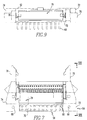
- the insulating housing of the receptacle is shown generally at numeral 10.
- This receptacle housing includes a front side wall 12, a rear sidewall 14, and upper engagement surface 15 and a lower engagement surface 16 and opposed end walls 17 and 18.
- a ribbon cable engagement member shown generally at numeral 24 which is spaced from the upper engagement surface by a ribbon cable receiving slot 26 and which are fixed to the vertical latch engagement ribs of the receptacle by vertical latches as at 27.
- IDC terminals as at 28 are positioned between the front and rear side walls and extend upwardly through the upper engagement surface to connect with ribbon cable inserted into the ribbon cable receiving slot.
- On the front wall there is a vertical keying projection 30.
- On the lower engagement surface there are a plurality of unrestricted windows as at 32 through which pins from a mating header (not shown) pass.
- Each of these windows is surrounded by a first pair and a second pair and inwardly sloping sides 36 and 38 and 40 and 42, respectively.
- Sides 40 and 42 have, respectively, inwardly projecting ledges 43 and 44 having terminal edges, respectively, at 45 and 46 extending into the window so as to produce a restricted vertical passageway as at 48 (Fig. 4) which beyond these ledges returns to a widened vertical passageway as at 50 (Fig. 4.)
- the terminal as at 28 (Fig. 5) is visible through the window.
- the ledges would preferably restrict the width of the window to a width which is about 4% to about 6% less than the width or diameter of the pin which is received in the window.
- the edges would also have a thickness (in the vertical direction as shown in Fig. 4) of from about .015 inch to about .025 inch.
- a connector employing a receptacle as described above will include a header shown generally at numeral 54.
- a header includes a base member 56 with a plurality of pins, each of which includes an upper section as at 58 (Figs. 11-12) and a lower perpendicular section at 60.
- Extending upwardly from the base is a front wall 62 which has a key engaging slot 64.
- Also positioned on the base are mounting apertures as at 66 and 68.
- rear wall 70 In opposed relation to the front wall is rear wall 70 to further surround the position for engagement with receptacles there are end walls 72 and 74 and on these end walls there are, respectively, pivoting latches 76 and 78.
- a receptacle identical to the one shown in Figs. 1-6 is shown generally at numeral 79 and is engaged with the header 54.
- Fig. 10 it will be seen that on the lower engagement surface 80 of the receptacle there are a plurality of unrestricted windows as at 82 which receive pins from the header and a plurality of restricted windows as at 84 which also receive pins from the mating header.
- Each of these windows is surrounded by an inwardly sloping first pair of sides 86 and 88 and second pair of sides 90 and 92.
- each of the terminals as at 52 have an upper insulation displacement section 98 which protrudes from the receptacle and which has a vertical slot 100 for receiving conductors in a ribbon cable.
- a lateral leg 102 is engaged in a recess 104 in the receptacle housing and a vertical wall 105 in the receptacle housing engages a vertical slot 106 in the terminal.
- a bore 108 having a restricted section 110.
- a lower leg 112 of the terminal extends into this bore.
- the lower leg has an upper inwardly angled section 114 and a lower outwardly angled section 116 with a medial apex 118 between them, and on the side of the terminal abutting the pin a contact surface 119 is formed.
- the ledges extend in a direction normal to the plane of this contact surface.
- the insulative housing of the receptacle is shown generally at numeral 122.
- this receptacle housing includes a front side wall 124, a rear sidewall 126, an upper engagement surface (not shown) and a lower engagement surface 128.
- superimposed over the upper engagement surface there is a ribbon cable engagement member (not shown) which is spaced from the upper engagement surface by a ribbon cable receiving slot (not shown) through the upper engagement surface to connect with ribbon cable inserted into the ribbon cable receiving slot.
- a vertical keying projection 136 On the front wall there is a vertical keying projection 136.
- a plurality of unrestricted windows as at 138 through which pins from a mating header pass.
- Each of these windows is surrounded by a first pair of inwardly sloping sides 142 and 144 and a second pair of inwardly sloping sides 146 and 148.
- Sides 146 and 148 have, respectively, projecting ledges 150 and 152 extending into the window so as to produce a restricted section as at 154 (Fig. 15) of a vertical bore 155 (Fig. 14).
- these ledges have a curved edge as at 156 and that they have a medial area 157 at which they extend into the window further than at their ends.
- a terminal as at 158 (Fig. 14) is also visible through the window.
- ledges 150 and 152 extend into the windows by smaller amounts at their ends and by greater amounts medially so that they have, respectively, curved edges 160 and 162.
- a connector employing a receptacle 158 as described above will include a header shown generally at numeral 160.
- a header includes a base member generally at numeral 162 with a plurality of pins, each of which includes an upper vertical section (not shown) and a lower vertical section at 164 and 166.
- the base includes a front wall 168, a rear wall 170 and end walls 172 and 174.
- each of these windows is surrounded by an inwardly sloping first pair of sides and second pair of sides which have respectfully, inwardly projecting ledges having respectively ledges which extend from sides by a uniform distance so that edges are parallel to the sides. These ledges also produce a restricted window. In the same way as was shown in Figs.
- each of the terminals have an upper section which protrudes from the receptacle which has a vertical slot for engaging ribbon cable.
- a lateral leg is engaged in a recess in the receptacle housing and a vertical wall in the receptacle housing engages a vertical slot in the terminal.
- In the receptacle housing there is a vertical bore having a restricted section, and a lower leg of the terminal extends downwardly into this vertical bore.
- the lower leg has an upper inwardly angled section and a lower outwardly angled section with there being a medial apex between them.
- the unmodified receptacle was standard QUICKIE receptacle with 15 ⁇ inch gold plating (part no. 71601) which had unrestricted windows having both a width and length of .030 inch.
- the insulative housing and the ledges were composed of 30% by weight fiberglass reinforced polyester (DUPONT RYNITE).
- the first modified receptacle was mated with a BERGSTIK header also manufactured by Berg Electronics, Inc.
- the second modified receptacle was mated with a BERGSTIK header having a 15 ⁇ inch gold plated .025 inch square pins (part no. 98001)
- the unmodified receptacle was also mated with a 15 ⁇ inch gold plated, .025 in square pins BERGSTIK header (part no. 68001). Mating and unmating of these modified receptacles was carried out in ten successive cycles. The amount of force required to carry out such mating and unmating was measured and is shown respectively in Figs. 20 and 21.
- Figs. 20 and 21 The average mating and unmating force for the conventional receptacles is also shown respectively in Figs. 20 and 21. As will be seen from Figs. 20 and 21, surprising and unexpected increases in mating and unmating forces were achieved using the modified receptacles.
Applications Claiming Priority (2)
| Application Number | Priority Date | Filing Date | Title |
|---|---|---|---|
| US08/566,293 US5833498A (en) | 1995-12-28 | 1995-12-28 | Electrical connector having improved retention feature and receptacle for use therein |
| US566293 | 1995-12-28 |
Publications (3)
| Publication Number | Publication Date |
|---|---|
| EP0782220A2 true EP0782220A2 (fr) | 1997-07-02 |
| EP0782220A3 EP0782220A3 (fr) | 1998-08-05 |
| EP0782220B1 EP0782220B1 (fr) | 2003-06-04 |
Family
ID=24262293
Family Applications (1)
| Application Number | Title | Priority Date | Filing Date |
|---|---|---|---|
| EP96120904A Expired - Lifetime EP0782220B1 (fr) | 1995-12-28 | 1996-12-27 | Prise pour connecteur electrique avec moyens de retention pour une pluralite de raccords conducteurs |
Country Status (8)
| Country | Link |
|---|---|
| US (2) | US5833498A (fr) |
| EP (1) | EP0782220B1 (fr) |
| JP (1) | JPH09283234A (fr) |
| KR (1) | KR970054938A (fr) |
| CN (1) | CN1166703A (fr) |
| DE (1) | DE69628533D1 (fr) |
| SG (1) | SG66341A1 (fr) |
| TW (1) | TW308745B (fr) |
Cited By (12)
| Publication number | Priority date | Publication date | Assignee | Title |
|---|---|---|---|---|
| EP0836243A2 (fr) * | 1996-10-10 | 1998-04-15 | Berg Electronics Manufacturing B.V. | Connecteur à haute densité et procédé de fabrication |
| US6042389A (en) * | 1996-10-10 | 2000-03-28 | Berg Technology, Inc. | Low profile connector |
| US6093035A (en) * | 1996-06-28 | 2000-07-25 | Berg Technology, Inc. | Contact for use in an electrical connector |
| SG80086A1 (en) * | 1998-12-31 | 2001-04-17 | Connector Systems Tech Nv | Press fit sca connector |
| US6241535B1 (en) | 1996-10-10 | 2001-06-05 | Berg Technology, Inc. | Low profile connector |
| US6358068B1 (en) | 1996-10-10 | 2002-03-19 | Fci Americas Technology, Inc. | Stress resistant connector and method for reducing stress in housing thereof |
| EP1441417A3 (fr) * | 1996-10-10 | 2004-12-01 | Fci | Connecteur à haute densité et procédé de fabrication |
| US6969286B1 (en) | 2004-06-28 | 2005-11-29 | Samtec, Inc. | Connector having improved contacts with fusible members |
| EP2148394A3 (fr) * | 2008-07-25 | 2011-07-20 | Fujitsu Limited | Structure de connecteur, prise, réceptacle et dispositif électronique |
| US9831605B2 (en) | 2012-04-13 | 2017-11-28 | Fci Americas Technology Llc | High speed electrical connector |
| US9871323B2 (en) | 2012-07-11 | 2018-01-16 | Fci Americas Technology Llc | Electrical connector with reduced stack height |
| US10720721B2 (en) | 2009-03-19 | 2020-07-21 | Fci Usa Llc | Electrical connector having ribbed ground plate |
Families Citing this family (21)
| Publication number | Priority date | Publication date | Assignee | Title |
|---|---|---|---|---|
| US20060257725A1 (en) * | 2001-10-04 | 2006-11-16 | Ise Corporation | Energy Storage Cell Support Separator System for a Multiple Cell Module and Method of Use |
| US7218489B2 (en) * | 2001-10-04 | 2007-05-15 | Ise Corporation | High-power ultracapacitor energy storage pack and method of use |
| US20070002518A1 (en) * | 2001-10-04 | 2007-01-04 | Ise Corporation | High-Power Ultracapacitor Energy Storage Pack and Method of Use |
| US20090021871A1 (en) * | 2001-10-04 | 2009-01-22 | Ise Corporation | Energy Storage Pack Having Overvoltage Protection and Method of Protection |
| US20090190273A1 (en) * | 2001-10-04 | 2009-07-30 | Ise Corporation | Ultracapacitor Overvoltage Protection Circuit With Self Verification |
| US20080068801A1 (en) * | 2001-10-04 | 2008-03-20 | Ise Corporation | High-Power Ultracapacitor Energy Storage Cell Pack and Coupling Method |
| US20070020513A1 (en) * | 2001-10-04 | 2007-01-25 | Ise Corporation | Energy Storage Cell Support Separator and Cooling System for a Multiple Cell Module |
| US7085112B2 (en) * | 2001-10-04 | 2006-08-01 | Ise Corporation | High-power ultracapacitor energy storage pack and method of use |
| US6714391B2 (en) | 2001-10-04 | 2004-03-30 | Ise Research Corporation | Ultracapacitor energy storage cell pack and methods of assembling and cooling the same |
| JP3755880B2 (ja) * | 2003-06-11 | 2006-03-15 | 日本航空電子工業株式会社 | コネクタ |
| US6881102B2 (en) * | 2003-06-13 | 2005-04-19 | Tyco Electronics Corporation | Terminal locking mechanism for hybrid electrical connector |
| KR100658274B1 (ko) * | 2005-11-23 | 2006-12-14 | 삼성에스디아이 주식회사 | 휴대용 표시장치의 커넥터 |
| US7883350B2 (en) * | 2009-04-29 | 2011-02-08 | Molex Incorporated | Header connectors with rigid latches |
| EP2624034A1 (fr) | 2012-01-31 | 2013-08-07 | Fci | Dispositif de couplage optique démontable |
| USD727268S1 (en) | 2012-04-13 | 2015-04-21 | Fci Americas Technology Llc | Vertical electrical connector |
| US8944831B2 (en) | 2012-04-13 | 2015-02-03 | Fci Americas Technology Llc | Electrical connector having ribbed ground plate with engagement members |
| USD727852S1 (en) | 2012-04-13 | 2015-04-28 | Fci Americas Technology Llc | Ground shield for a right angle electrical connector |
| USD718253S1 (en) | 2012-04-13 | 2014-11-25 | Fci Americas Technology Llc | Electrical cable connector |
| USD751507S1 (en) | 2012-07-11 | 2016-03-15 | Fci Americas Technology Llc | Electrical connector |
| USD745852S1 (en) | 2013-01-25 | 2015-12-22 | Fci Americas Technology Llc | Electrical connector |
| USD720698S1 (en) | 2013-03-15 | 2015-01-06 | Fci Americas Technology Llc | Electrical cable connector |
Family Cites Families (19)
| Publication number | Priority date | Publication date | Assignee | Title |
|---|---|---|---|---|
| US2762026A (en) * | 1953-03-05 | 1956-09-04 | Illinois Tool Works | Electrical connector |
| US4030799A (en) * | 1976-02-09 | 1977-06-21 | A P Products Incorporated | Jumper connector |
| KR830003818A (ko) * | 1980-07-26 | 1983-06-22 | 요시야마 히로기찌 | 전자회로용 코넥터 |
| US4533188A (en) * | 1983-02-15 | 1985-08-06 | Motorola, Inc. | Header and housing assembly for electronic circuit modules |
| US4555154A (en) * | 1983-12-21 | 1985-11-26 | International Telephone & Telegraph Corp. | Electrical connector contact retention assembly |
| US4778396A (en) * | 1984-02-06 | 1988-10-18 | Amp Incorporated | Electrical connector having compliant posts and improved insertion characteristics |
| US4607907A (en) * | 1984-08-24 | 1986-08-26 | Burndy Corporation | Electrical connector requiring low mating force |
| US4863402A (en) * | 1986-10-17 | 1989-09-05 | Ohio Associated Enterprises, Inc. | Method and apparatus for making electrical connecting device |
| DE3637008A1 (de) * | 1986-10-30 | 1988-05-11 | Nixdorf Computer Ag | Anschlussvorrichtung fuer ein mehradriges abgeschirmtes kabel |
| KR890011145A (ko) * | 1987-12-15 | 1989-08-12 | 제이 엘.사이칙 | 핀 그리드 어레이용 소켓 |
| JPH0537435Y2 (fr) * | 1988-01-27 | 1993-09-21 | ||
| US5022870A (en) * | 1989-02-28 | 1991-06-11 | Murata Manufacturing Co., Ltd. | Retainer for connector terminals |
| NL8900920A (nl) * | 1989-04-13 | 1990-11-01 | Philips Nv | Inrichting bevattende een drager met openingen voor het plaatsen van pennen. |
| AU7736691A (en) * | 1990-06-08 | 1991-12-12 | E.I. Du Pont De Nemours And Company | Connectors with ground structure |
| SE466126B (sv) * | 1990-12-21 | 1991-12-16 | Vemako Ab | Flerpoligt skaermat kontaktdon med gemensam jord |
| US5169347A (en) * | 1991-10-15 | 1992-12-08 | Molex Incorporated | Slip-off electrical connector header |
| US5334053A (en) * | 1992-10-19 | 1994-08-02 | Burndy Corporation | Dual-beam electrical contact with preload tabs |
| US5582519A (en) * | 1994-12-15 | 1996-12-10 | The Whitaker Corporation | Make-first-break-last ground connections |
| US5588878A (en) * | 1995-03-14 | 1996-12-31 | The Whitaker Corporation | Electrical receptacle assembly and spring contact therefor |
-
1995
- 1995-12-28 US US08/566,293 patent/US5833498A/en not_active Expired - Fee Related
-
1996
- 1996-01-11 TW TW085100274A patent/TW308745B/zh active
- 1996-12-20 JP JP8342153A patent/JPH09283234A/ja active Pending
- 1996-12-25 CN CN96123424A patent/CN1166703A/zh active Pending
- 1996-12-27 KR KR1019960072767A patent/KR970054938A/ko not_active Application Discontinuation
- 1996-12-27 EP EP96120904A patent/EP0782220B1/fr not_active Expired - Lifetime
- 1996-12-27 DE DE69628533T patent/DE69628533D1/de not_active Expired - Lifetime
- 1996-12-28 SG SG1996011937A patent/SG66341A1/en unknown
-
1998
- 1998-11-09 US US09/189,371 patent/US6033267A/en not_active Expired - Fee Related
Non-Patent Citations (1)
| Title |
|---|
| None |
Cited By (20)
| Publication number | Priority date | Publication date | Assignee | Title |
|---|---|---|---|---|
| US6093035A (en) * | 1996-06-28 | 2000-07-25 | Berg Technology, Inc. | Contact for use in an electrical connector |
| EP0836243A2 (fr) * | 1996-10-10 | 1998-04-15 | Berg Electronics Manufacturing B.V. | Connecteur à haute densité et procédé de fabrication |
| EP0836243A3 (fr) * | 1996-10-10 | 1999-05-06 | Berg Electronics Manufacturing B.V. | Connecteur à haute densité et procédé de fabrication |
| US6042389A (en) * | 1996-10-10 | 2000-03-28 | Berg Technology, Inc. | Low profile connector |
| US6241535B1 (en) | 1996-10-10 | 2001-06-05 | Berg Technology, Inc. | Low profile connector |
| US6325644B1 (en) | 1996-10-10 | 2001-12-04 | Berg Technology, Inc. | High density connector and method of manufacture |
| US6358068B1 (en) | 1996-10-10 | 2002-03-19 | Fci Americas Technology, Inc. | Stress resistant connector and method for reducing stress in housing thereof |
| EP1441417A3 (fr) * | 1996-10-10 | 2004-12-01 | Fci | Connecteur à haute densité et procédé de fabrication |
| SG80086A1 (en) * | 1998-12-31 | 2001-04-17 | Connector Systems Tech Nv | Press fit sca connector |
| US6979238B1 (en) | 2004-06-28 | 2005-12-27 | Samtec, Inc. | Connector having improved contacts with fusible members |
| US6969286B1 (en) | 2004-06-28 | 2005-11-29 | Samtec, Inc. | Connector having improved contacts with fusible members |
| US7052337B2 (en) | 2004-06-28 | 2006-05-30 | Samtec, Inc. | Connector having improved contacts with fusible members |
| US7125293B2 (en) | 2004-06-28 | 2006-10-24 | Samtec, Inc. | Connector having improved contacts with fusible members |
| US7159312B2 (en) | 2004-06-28 | 2007-01-09 | Samtec, Inc. | Connector having improved contacts with fusible members |
| US7178232B2 (en) | 2004-06-28 | 2007-02-20 | Samtec, Inc. | Connector having improved contacts with fusible members |
| EP2148394A3 (fr) * | 2008-07-25 | 2011-07-20 | Fujitsu Limited | Structure de connecteur, prise, réceptacle et dispositif électronique |
| US8092259B2 (en) | 2008-07-25 | 2012-01-10 | Fujitsu Limited | Connector structure, plug connector, receptacle connector and electronic device |
| US10720721B2 (en) | 2009-03-19 | 2020-07-21 | Fci Usa Llc | Electrical connector having ribbed ground plate |
| US9831605B2 (en) | 2012-04-13 | 2017-11-28 | Fci Americas Technology Llc | High speed electrical connector |
| US9871323B2 (en) | 2012-07-11 | 2018-01-16 | Fci Americas Technology Llc | Electrical connector with reduced stack height |
Also Published As
| Publication number | Publication date |
|---|---|
| JPH09283234A (ja) | 1997-10-31 |
| DE69628533D1 (de) | 2003-07-10 |
| TW308745B (en) | 1997-06-21 |
| EP0782220A3 (fr) | 1998-08-05 |
| CN1166703A (zh) | 1997-12-03 |
| US5833498A (en) | 1998-11-10 |
| SG66341A1 (en) | 1999-07-20 |
| US6033267A (en) | 2000-03-07 |
| KR970054938A (ko) | 1997-07-31 |
| EP0782220B1 (fr) | 2003-06-04 |
Similar Documents
| Publication | Publication Date | Title |
|---|---|---|
| EP0782220B1 (fr) | Prise pour connecteur electrique avec moyens de retention pour une pluralite de raccords conducteurs | |
| US10063006B2 (en) | Wire mount electrical connector | |
| US9876285B2 (en) | Electrical connector contact terminal | |
| US6171126B1 (en) | Battery receptacle connector | |
| US5498167A (en) | Board to board electrical connectors | |
| US4241970A (en) | Electrical connector having improved receptacle terminal | |
| EP0632541B1 (fr) | Connecteur électrique pour câble plat à haute densité | |
| US9509094B2 (en) | Board mount electrical connector with latch opening on bottom wall | |
| EP0795929A2 (fr) | Assemblage de connecteur électrique avec des caractéristiques de fixation améliorées | |
| US20060141826A1 (en) | Receptacle | |
| US9509089B2 (en) | Electrical connector latch | |
| US5468156A (en) | Locking system for interconnection of daughter board and mother board assemblies | |
| US9553401B2 (en) | Electrical connector for strain relief for an electrical cable | |
| US5145422A (en) | Female electrical terminal with improved contact force | |
| US6244887B1 (en) | Electrical connector assembly | |
| US7234957B2 (en) | Electrical connector assembly having locking mechanism | |
| US4895532A (en) | Modular connector coupler with selective commoning system | |
| US4632492A (en) | Electrical connector assembly | |
| US6162081A (en) | Electrical connector terminal arrangement | |
| KR950012467B1 (ko) | 전기 접속기용 단자 로킹 장치 | |
| EP0549908A2 (fr) | Assemblage de bornes électriques avec élément de verrouillage | |
| US6302722B1 (en) | Mating/unmating system for electrical connectors |
Legal Events
| Date | Code | Title | Description |
|---|---|---|---|
| PUAI | Public reference made under article 153(3) epc to a published international application that has entered the european phase |
Free format text: ORIGINAL CODE: 0009012 |
|
| AK | Designated contracting states |
Kind code of ref document: A2 Designated state(s): DE FR GB |
|
| PUAL | Search report despatched |
Free format text: ORIGINAL CODE: 0009013 |
|
| AK | Designated contracting states |
Kind code of ref document: A3 Designated state(s): DE FR GB |
|
| 17P | Request for examination filed |
Effective date: 19981211 |
|
| 17Q | First examination report despatched |
Effective date: 19990319 |
|
| GRAH | Despatch of communication of intention to grant a patent |
Free format text: ORIGINAL CODE: EPIDOS IGRA |
|
| RAP1 | Party data changed (applicant data changed or rights of an application transferred) |
Owner name: FCI |
|
| GRAH | Despatch of communication of intention to grant a patent |
Free format text: ORIGINAL CODE: EPIDOS IGRA |
|
| GRAA | (expected) grant |
Free format text: ORIGINAL CODE: 0009210 |
|
| RIC1 | Information provided on ipc code assigned before grant |
Ipc: 7H 01R 13/422 B Ipc: 7H 01R 13/40 B Ipc: 7H 01R 13/42 B Ipc: 7H 01R 24/00 A |
|
| AK | Designated contracting states |
Designated state(s): DE FR GB |
|
| PG25 | Lapsed in a contracting state [announced via postgrant information from national office to epo] |
Ref country code: FR Free format text: LAPSE BECAUSE OF FAILURE TO SUBMIT A TRANSLATION OF THE DESCRIPTION OR TO PAY THE FEE WITHIN THE PRESCRIBED TIME-LIMIT Effective date: 20030604 |
|
| REG | Reference to a national code |
Ref country code: GB Ref legal event code: FG4D |
|
| REF | Corresponds to: |
Ref document number: 69628533 Country of ref document: DE Date of ref document: 20030710 Kind code of ref document: P |
|
| PG25 | Lapsed in a contracting state [announced via postgrant information from national office to epo] |
Ref country code: DE Free format text: LAPSE BECAUSE OF FAILURE TO SUBMIT A TRANSLATION OF THE DESCRIPTION OR TO PAY THE FEE WITHIN THE PRESCRIBED TIME-LIMIT Effective date: 20030905 |
|
| PG25 | Lapsed in a contracting state [announced via postgrant information from national office to epo] |
Ref country code: GB Free format text: LAPSE BECAUSE OF NON-PAYMENT OF DUE FEES Effective date: 20031227 |
|
| PLBE | No opposition filed within time limit |
Free format text: ORIGINAL CODE: 0009261 |
|
| STAA | Information on the status of an ep patent application or granted ep patent |
Free format text: STATUS: NO OPPOSITION FILED WITHIN TIME LIMIT |
|
| 26N | No opposition filed |
Effective date: 20040305 |
|
| EN | Fr: translation not filed | ||
| GBPC | Gb: european patent ceased through non-payment of renewal fee |
Effective date: 20031227 |