EP0782209A1 - Versorgungsanordnung mit Brennstoffzellen und Pufferbatterie für energieautonome Fahrzeug mit elektrischem Antrieb - Google Patents
Versorgungsanordnung mit Brennstoffzellen und Pufferbatterie für energieautonome Fahrzeug mit elektrischem Antrieb Download PDFInfo
- Publication number
- EP0782209A1 EP0782209A1 EP95830562A EP95830562A EP0782209A1 EP 0782209 A1 EP0782209 A1 EP 0782209A1 EP 95830562 A EP95830562 A EP 95830562A EP 95830562 A EP95830562 A EP 95830562A EP 0782209 A1 EP0782209 A1 EP 0782209A1
- Authority
- EP
- European Patent Office
- Prior art keywords
- battery
- converter
- voltage
- power
- load
- Prior art date
- Legal status (The legal status is an assumption and is not a legal conclusion. Google has not performed a legal analysis and makes no representation as to the accuracy of the status listed.)
- Ceased
Links
Images


Classifications
-
- H—ELECTRICITY
- H02—GENERATION; CONVERSION OR DISTRIBUTION OF ELECTRIC POWER
- H02J—CIRCUIT ARRANGEMENTS OR SYSTEMS FOR SUPPLYING OR DISTRIBUTING ELECTRIC POWER; SYSTEMS FOR STORING ELECTRIC ENERGY
- H02J7/00—Circuit arrangements for charging or depolarising batteries or for supplying loads from batteries
- H02J7/34—Parallel operation in networks using both storage and other dc sources, e.g. providing buffering
-
- B—PERFORMING OPERATIONS; TRANSPORTING
- B60—VEHICLES IN GENERAL
- B60L—PROPULSION OF ELECTRICALLY-PROPELLED VEHICLES; SUPPLYING ELECTRIC POWER FOR AUXILIARY EQUIPMENT OF ELECTRICALLY-PROPELLED VEHICLES; ELECTRODYNAMIC BRAKE SYSTEMS FOR VEHICLES IN GENERAL; MAGNETIC SUSPENSION OR LEVITATION FOR VEHICLES; MONITORING OPERATING VARIABLES OF ELECTRICALLY-PROPELLED VEHICLES; ELECTRIC SAFETY DEVICES FOR ELECTRICALLY-PROPELLED VEHICLES
- B60L58/00—Methods or circuit arrangements for monitoring or controlling batteries or fuel cells, specially adapted for electric vehicles
- B60L58/10—Methods or circuit arrangements for monitoring or controlling batteries or fuel cells, specially adapted for electric vehicles for monitoring or controlling batteries
-
- B—PERFORMING OPERATIONS; TRANSPORTING
- B60—VEHICLES IN GENERAL
- B60L—PROPULSION OF ELECTRICALLY-PROPELLED VEHICLES; SUPPLYING ELECTRIC POWER FOR AUXILIARY EQUIPMENT OF ELECTRICALLY-PROPELLED VEHICLES; ELECTRODYNAMIC BRAKE SYSTEMS FOR VEHICLES IN GENERAL; MAGNETIC SUSPENSION OR LEVITATION FOR VEHICLES; MONITORING OPERATING VARIABLES OF ELECTRICALLY-PROPELLED VEHICLES; ELECTRIC SAFETY DEVICES FOR ELECTRICALLY-PROPELLED VEHICLES
- B60L58/00—Methods or circuit arrangements for monitoring or controlling batteries or fuel cells, specially adapted for electric vehicles
- B60L58/30—Methods or circuit arrangements for monitoring or controlling batteries or fuel cells, specially adapted for electric vehicles for monitoring or controlling fuel cells
- B60L58/32—Methods or circuit arrangements for monitoring or controlling batteries or fuel cells, specially adapted for electric vehicles for monitoring or controlling fuel cells for controlling the temperature of fuel cells, e.g. by controlling the electric load
- B60L58/33—Methods or circuit arrangements for monitoring or controlling batteries or fuel cells, specially adapted for electric vehicles for monitoring or controlling fuel cells for controlling the temperature of fuel cells, e.g. by controlling the electric load by cooling
-
- H—ELECTRICITY
- H01—ELECTRIC ELEMENTS
- H01M—PROCESSES OR MEANS, e.g. BATTERIES, FOR THE DIRECT CONVERSION OF CHEMICAL ENERGY INTO ELECTRICAL ENERGY
- H01M16/00—Structural combinations of different types of electrochemical generators
- H01M16/003—Structural combinations of different types of electrochemical generators of fuel cells with other electrochemical devices, e.g. capacitors, electrolysers
- H01M16/006—Structural combinations of different types of electrochemical generators of fuel cells with other electrochemical devices, e.g. capacitors, electrolysers of fuel cells with rechargeable batteries
-
- H—ELECTRICITY
- H01—ELECTRIC ELEMENTS
- H01M—PROCESSES OR MEANS, e.g. BATTERIES, FOR THE DIRECT CONVERSION OF CHEMICAL ENERGY INTO ELECTRICAL ENERGY
- H01M8/00—Fuel cells; Manufacture thereof
- H01M8/04—Auxiliary arrangements, e.g. for control of pressure or for circulation of fluids
- H01M8/04298—Processes for controlling fuel cells or fuel cell systems
- H01M8/04313—Processes for controlling fuel cells or fuel cell systems characterised by the detection or assessment of variables; characterised by the detection or assessment of failure or abnormal function
- H01M8/04537—Electric variables
- H01M8/04544—Voltage
- H01M8/04567—Voltage of auxiliary devices, e.g. batteries, capacitors
-
- H—ELECTRICITY
- H01—ELECTRIC ELEMENTS
- H01M—PROCESSES OR MEANS, e.g. BATTERIES, FOR THE DIRECT CONVERSION OF CHEMICAL ENERGY INTO ELECTRICAL ENERGY
- H01M8/00—Fuel cells; Manufacture thereof
- H01M8/04—Auxiliary arrangements, e.g. for control of pressure or for circulation of fluids
- H01M8/04298—Processes for controlling fuel cells or fuel cell systems
- H01M8/04313—Processes for controlling fuel cells or fuel cell systems characterised by the detection or assessment of variables; characterised by the detection or assessment of failure or abnormal function
- H01M8/04537—Electric variables
- H01M8/04574—Current
-
- H—ELECTRICITY
- H01—ELECTRIC ELEMENTS
- H01M—PROCESSES OR MEANS, e.g. BATTERIES, FOR THE DIRECT CONVERSION OF CHEMICAL ENERGY INTO ELECTRICAL ENERGY
- H01M8/00—Fuel cells; Manufacture thereof
- H01M8/04—Auxiliary arrangements, e.g. for control of pressure or for circulation of fluids
- H01M8/04298—Processes for controlling fuel cells or fuel cell systems
- H01M8/04694—Processes for controlling fuel cells or fuel cell systems characterised by variables to be controlled
- H01M8/04858—Electric variables
- H01M8/04925—Power, energy, capacity or load
- H01M8/0494—Power, energy, capacity or load of fuel cell stacks
-
- H—ELECTRICITY
- H01—ELECTRIC ELEMENTS
- H01M—PROCESSES OR MEANS, e.g. BATTERIES, FOR THE DIRECT CONVERSION OF CHEMICAL ENERGY INTO ELECTRICAL ENERGY
- H01M8/00—Fuel cells; Manufacture thereof
- H01M8/04—Auxiliary arrangements, e.g. for control of pressure or for circulation of fluids
- H01M8/04298—Processes for controlling fuel cells or fuel cell systems
- H01M8/04313—Processes for controlling fuel cells or fuel cell systems characterised by the detection or assessment of variables; characterised by the detection or assessment of failure or abnormal function
- H01M8/04537—Electric variables
- H01M8/04544—Voltage
- H01M8/04559—Voltage of fuel cell stacks
-
- H—ELECTRICITY
- H01—ELECTRIC ELEMENTS
- H01M—PROCESSES OR MEANS, e.g. BATTERIES, FOR THE DIRECT CONVERSION OF CHEMICAL ENERGY INTO ELECTRICAL ENERGY
- H01M8/00—Fuel cells; Manufacture thereof
- H01M8/04—Auxiliary arrangements, e.g. for control of pressure or for circulation of fluids
- H01M8/04298—Processes for controlling fuel cells or fuel cell systems
- H01M8/04313—Processes for controlling fuel cells or fuel cell systems characterised by the detection or assessment of variables; characterised by the detection or assessment of failure or abnormal function
- H01M8/04537—Electric variables
- H01M8/04574—Current
- H01M8/04589—Current of fuel cell stacks
-
- H—ELECTRICITY
- H01—ELECTRIC ELEMENTS
- H01M—PROCESSES OR MEANS, e.g. BATTERIES, FOR THE DIRECT CONVERSION OF CHEMICAL ENERGY INTO ELECTRICAL ENERGY
- H01M8/00—Fuel cells; Manufacture thereof
- H01M8/04—Auxiliary arrangements, e.g. for control of pressure or for circulation of fluids
- H01M8/04298—Processes for controlling fuel cells or fuel cell systems
- H01M8/04313—Processes for controlling fuel cells or fuel cell systems characterised by the detection or assessment of variables; characterised by the detection or assessment of failure or abnormal function
- H01M8/04537—Electric variables
- H01M8/04574—Current
- H01M8/04597—Current of auxiliary devices, e.g. batteries, capacitors
-
- Y—GENERAL TAGGING OF NEW TECHNOLOGICAL DEVELOPMENTS; GENERAL TAGGING OF CROSS-SECTIONAL TECHNOLOGIES SPANNING OVER SEVERAL SECTIONS OF THE IPC; TECHNICAL SUBJECTS COVERED BY FORMER USPC CROSS-REFERENCE ART COLLECTIONS [XRACs] AND DIGESTS
- Y02—TECHNOLOGIES OR APPLICATIONS FOR MITIGATION OR ADAPTATION AGAINST CLIMATE CHANGE
- Y02E—REDUCTION OF GREENHOUSE GAS [GHG] EMISSIONS, RELATED TO ENERGY GENERATION, TRANSMISSION OR DISTRIBUTION
- Y02E60/00—Enabling technologies; Technologies with a potential or indirect contribution to GHG emissions mitigation
- Y02E60/10—Energy storage using batteries
-
- Y—GENERAL TAGGING OF NEW TECHNOLOGICAL DEVELOPMENTS; GENERAL TAGGING OF CROSS-SECTIONAL TECHNOLOGIES SPANNING OVER SEVERAL SECTIONS OF THE IPC; TECHNICAL SUBJECTS COVERED BY FORMER USPC CROSS-REFERENCE ART COLLECTIONS [XRACs] AND DIGESTS
- Y02—TECHNOLOGIES OR APPLICATIONS FOR MITIGATION OR ADAPTATION AGAINST CLIMATE CHANGE
- Y02E—REDUCTION OF GREENHOUSE GAS [GHG] EMISSIONS, RELATED TO ENERGY GENERATION, TRANSMISSION OR DISTRIBUTION
- Y02E60/00—Enabling technologies; Technologies with a potential or indirect contribution to GHG emissions mitigation
- Y02E60/30—Hydrogen technology
- Y02E60/50—Fuel cells
-
- Y—GENERAL TAGGING OF NEW TECHNOLOGICAL DEVELOPMENTS; GENERAL TAGGING OF CROSS-SECTIONAL TECHNOLOGIES SPANNING OVER SEVERAL SECTIONS OF THE IPC; TECHNICAL SUBJECTS COVERED BY FORMER USPC CROSS-REFERENCE ART COLLECTIONS [XRACs] AND DIGESTS
- Y02—TECHNOLOGIES OR APPLICATIONS FOR MITIGATION OR ADAPTATION AGAINST CLIMATE CHANGE
- Y02T—CLIMATE CHANGE MITIGATION TECHNOLOGIES RELATED TO TRANSPORTATION
- Y02T10/00—Road transport of goods or passengers
- Y02T10/60—Other road transportation technologies with climate change mitigation effect
- Y02T10/70—Energy storage systems for electromobility, e.g. batteries
-
- Y—GENERAL TAGGING OF NEW TECHNOLOGICAL DEVELOPMENTS; GENERAL TAGGING OF CROSS-SECTIONAL TECHNOLOGIES SPANNING OVER SEVERAL SECTIONS OF THE IPC; TECHNICAL SUBJECTS COVERED BY FORMER USPC CROSS-REFERENCE ART COLLECTIONS [XRACs] AND DIGESTS
- Y02—TECHNOLOGIES OR APPLICATIONS FOR MITIGATION OR ADAPTATION AGAINST CLIMATE CHANGE
- Y02T—CLIMATE CHANGE MITIGATION TECHNOLOGIES RELATED TO TRANSPORTATION
- Y02T90/00—Enabling technologies or technologies with a potential or indirect contribution to GHG emissions mitigation
- Y02T90/40—Application of hydrogen technology to transportation, e.g. using fuel cells
Definitions
- the present invention relates to a supply system with fuel cells and a buffer battery for a self-supplied vehicle with electric drive.
- Electric drive with a battery supply does not limit the mobility of the vehicles to obligatory routes but is seriously limited in terms of autonomy.
- a first solution to these problems was the production of hybrid diesel/electric and battery vehicles in which a diesel engine operating at a constant speed at the point of minimum specific consumption drives an electric generator which continuously recharges a buffer battery for supplying electrical loads.
- the publication WO93/09572 describes a system for supplying an electric motor of an electric vehicle in which fuel cells recharge a buffer battery and the connection between the two elements is made by means of a generic voltage regulator the characteristics of which are not specified.
- a basic problem in the production of hybrid vehicles of this type is constituted precisely by the interfacing of the fuel cells with the buffer battery and by the adjustment of the power delivered by the fuel cells in dependence on the load requirement of the vehicle and the charge state of the batteries.
- the power output available from the stacks (or blocks) of fuel cells for practical use in vehicles is in fact associated with voltage and current values which are not compatible with the drive system which, in order to limit the current to values which can be withstood by the electronic components on the market, requires a sufficiently high voltage.
- the static internal resistance of the fuel cells is comparable to that of the battery, be it of the nickel-cadmium or of the lead type, in contrast, the fuel cells are much slower to adapt to transients of the power delivered and have a very high internal dynamic resistance and considerable hysteresis which is not compatible with the abrupt changes in load and power required of a vehicle.
- the present invention solves this technical problem and provides a supply system with fuel cells and a buffer battery in which a highly efficient, very safe and extremely simple electronic regulation system forms the interface and ensures optimal performance of the drive system.
- the electronic regulation system performs the following functions:
- an electronic regulation system comprising a resonant converter with series load connected to the output of the fuel cells, a high-frequency step-up transformer with its primary connected to the output of the converter, and a rectifier bridge with fast diodes with its input connected to the secondary of the transformer and its output connected to the battery and logic control circuits.
- the latter detect the current absorbed by the load and the battery voltage and modify the working frequency of the converter so as to control the current, and hence the power, delivered.
- the voltage output by the supply system is continuously adjusted in relation to the battery voltage.
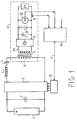
- the hybrid supply system of the present invention comprises a stack of fuel cells 1 (preferably of the type with a solid polymer electrolyte SPE), an input capacitor 2, an H-shaped conversion bridge 3 for converting direct-current voltage to alternating pulses, the bridge being supplied by the stack of cells 1 and in turn supplying, arranged in series, an inductance L, a capacitor C and the primary 4 of a transformer 5 of which the secondary 51 is connected to the input of a diode rectifier bridge 6.
- a stack of fuel cells 1 preferably of the type with a solid polymer electrolyte SPE
- an input capacitor 2 for converting direct-current voltage to alternating pulses
- the bridge being supplied by the stack of cells 1 and in turn supplying, arranged in series, an inductance L, a capacitor C and the primary 4 of a transformer 5 of which the secondary 51 is connected to the input of a diode rectifier bridge 6.
- These diodes are preferably of the fast-recovery ISOTOPV type.
- the output of the bridge 6 is connected to the terminals of a capacitive filter 7 and to the terminals of a buffer battery 8 which in turn supplies a variable load Z1 constituted by drive members of the vehicle and by the electronic control system thereof.
- the system is completed by a sensor 9 for detecting the current absorbed by the load, a sensor 10 for detecting the supply voltage delivered by the battery 8, and control logic 11 which generates a periodic variable-frequency control signal F for controlling the switching frequency of the conversion bridge 3 in dependence on the battery voltage and the load current.
- control logic 11 is completed by phase control logic 12 which generates, in dependence on the signal F, a plurality of control signals which are applied to each of the electronic switches of the conversion bridge 3 individually.
- the conversion bridge 3 which is intended to operate at a fairly high switching frequency of from 10 to 40 KHz and more, is constituted by IGBT (insulated gate bipolar transistor) electronic switches.
- IGBT insulated gate bipolar transistor
- Their working frequency is of the order of from 10 to 100KHz according to the power switched.
- Each IGBT is associated with a fast antiparallel diode, in known manner, to enable it to operate with half-cycles of current of opposite senses, and a local control circuit which switches it on and off for a predetermined conduction interval P at a frequency set by the signal F.
- This local control circuit is shown schematically for all four IGBTs by the block 12.
- the conversion bridge 3 together with the inductance L, the capacitor C and the series load Z formed by the transformer 4 and by the loads supplied thereby, forms a resonant bridge converter with series load.
- a resonant converter is operated with variations of the switching frequency.
- a full-wave quasi-resonant converter (the bridge configuration of the converter ensures full-wave resonance) with a series load enables the switches to be closed and opened when the current flowing in the switches is theoretically zero.
- a full-cycle semi-resonant converter also has the property that if the impedance/resistance of the load Z is less than the square root of the ratio between the inductance and the capacitance of the resonant circuit, that is, if, in the case of a purely resistive load R ⁇ L/C , the amplitude of the sinusoidal current pulses introduced into the network and of the corresponding current pulses available in the secondary of the transformer 5 is substantially independent of the load impedance and depends solely on the supply voltage and on the values of L and C.
- the average value of the current delivered to the load by a full-cycle quasi-resonant generator is proportional to the number of current pulses introduced per unit of time and hence to the switching frequency F.
- the transformer 5 has to have a turns ratio adequate to take account of the need to apply voltage and current pulses to an active load constituted by a voltage generator (battery) in opposition to the pulse voltage which is output by the transformer and applied to the load by means of the diode bridge.
- the turns ratio NS/NP of the transformer (where NP is the number of primary turns and NS is the number of secondary turns) to be greater than 1 and, theoretically, the ratio between the maximum battery voltage and the minimum voltage delivered by the fuel cell is preferably of the order of twice the ratio between the mean value of the battery voltage and the mean value of the voltage delivered by the fuel cells.
- the drawback of the use of a quasi-resonant converter is that the maximum current is delivered when the switching frequency is at a maximum and equal to half the resonance frequency.
- the switching frequency of the converter is equal to or greater than the resonance frequency of the circuit and the current delivered decreases as the frequency increases by a law determined by the impedance of the resonant circuit (which is variable with frequency).
- the switching of the switches of the converter takes place with zero current only for a switching frequency equal to the resonance frequency and, for higher frequencies, the current is not zero but is nevertheless less than the peak current and decreases with increase in frequency.
- the advantage is thus achieved that the losses in the transformer in the various load conditions are equalized to a certain extent and, for all load conditions, have a value which is much less than would occur in the case of a converter operating discontinuously at the maximum frequency and at the corresponding maximum load.
- Figure 2 shows as a graph of the voltage V and the current IFC, the static characteristic of an SPE fuel cell (in practice formed by a stack of cells) used in the present application and shows that the voltage delivered with a load of between a few A up to 100 A varies linearly between about 640 and 500 V.
- the load limit of 100 A is dictated by structural concerns and corresponds to the maximum power which can be delivered by the cell.
- the internal resistance of the cell is about 1.7-1.8 ⁇ .
- the static characteristic shown also describes the behaviour of the cell in dynamic conditions if the increases in load over time are less than a predetermined limit of the order of 80A/s.
- the maximum permissible power delivered by the fuel cell is of the order of 50 KW and advantageously constitutes a fraction of between 10% and 30% (for example, 20%) of the peak power required by the drive system, and is equal to the mean value of the power absorbed by the drive system within the daily working span, increased by a value of between 10% and 20% to take account of the conversion efficiency at the various levels and to permit buffer operation of the fuel cell which, on average, can meet the daily energy requirements.
- Figure 3 shows as a graph of voltage V and current IL, two electrical characteristics D, E of a nickel cadmium battery for use in the present application, corresponding, respectively, to a state of minimum accumulated charge (graph D) and to a state of maximum accumulated charge (graph E) in the battery.
- the apparent internal resistance of the battery varies between about 0.4 ⁇ and 0.75 ⁇ .
- a predetermined voltage measured at the terminals of the battery does not unequivocally identify a working point of the battery but identifies a plurality of possible working points.
- the pair of values V, I also defines the charge state of the battery.
- the working point of the battery does not fully define the working condition of the supply system and indicates only the algebraic sum of the current delivered by the fuel cell through the converter and the current absorbed by the load.
- the maximum permissible power delivered by the battery is of the order of 150 KW, which is about 80% of the peak power (180 KW) required by the system in drive: in fact, the peak power output is achieved with the participation of both the battery and the fuel cells.
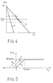
- Figure 4 shows the output electrical characteristics of the system constituted by the fuel cells and by the converter, connected to an active load (a voltage generator) such as a battery.
- an active load a voltage generator
- the mean current output by the converter (or more precisely by the rectifier bridge) is independent of the load value and depends solely on the switching frequency of the converter.
- the output characteristic V, I (with a constant supply voltage) for any predetermined working frequency would be virtually a vertical line corresponding to a predetermined output current.
- the working point or the voltage V would be set by the power absorbed by the load.
- V,I of the system are segments F, G extending like rays from a working point with zero current and voltage VI with downward slopes which are variable in dependence on the switching frequency.
- the slope decreases as the switching frequency increased if the converter operates discontinuously (a quasi-resonant converter) and increases with increases in switching frequency if the converter operates continuously.
- G For values of the voltage VG close to half of the voltage VI the characteristics F, G also represent curves of load at constant power.
- the range of variation of the battery voltages in the various load conditions for the various charge states is of the order of ⁇ 25% relative to a mean value, it may be considered, with a negligible error, that, throughout the range of variation, the various characteristics represent a power output which depends exclusively on the switching frequency of the converter.
- the graph G represents the maximum power delivered at the minimum switching frequency F; the latter, as a minimum, may equal the resonance frequency f of the converter and corresponds to 10 KHz.
- the graph F represents the minimum power delivered at the maximum switching frequency; for example, the minimum power is 20% of the maximum power and corresponds to a switching frequency of the order of 40 KHz.
- the graph G represents the maximum power delivered at the maximum switching frequency F, for example 40 KHz which, at the maximum, may be 1/2 of the resonance frequency f of the converter.
- the graph F represents the minimum power delivered at the minimum switching frequency; for example, this is 20% of the maximum power and corresponds to a switching frequency of the order of 10 KHz.
- Figure 4 represents both the electrical characteristics of the conversion system applied to the primary of the transformer and those applied to the secondary.
- the electrical characteristics of the fuel cell/converter system of Figure 4 specularly transposed (to take account of the fact that the currents output by the system are input to the battery) and translated relative to the origin of the abscissa by a distance corresponding to a generic load current IL, define the working point of the supply system in dependence on the switching frequency of the converter, on the load current IL, and on the charge state of the battery.
- the characteristics F, G of Figure 4 correspond to the characteristics F1, G1 of Figure 3.
- the power delivered can be varied simply by varying the switching frequency according to a predetermined regulation characteristic.
- a regulation characteristic which is preferred owing to its simplicity and which requires solely the measurement of the battery voltage and the load current is represented in the regulation graph of Figure 5 which shows the power PFC delivered by the fuel cell as available to the output of the converter, as a function of the power PL absorbed by the load L.
- the power delivered by the fuel cell is kept constant and equal to the maximum PFCMAX so as to make a maximum contribution to the load requirement.
- the power delivered by the fuel cell is made to depend upon the charge state of the battery.
- the power PFC delivered by the cell is equal to the load power PL (graph H).
- the regulation band is proportional and is displaced in accordance with the lower voltage so as to deliver a recharging power to the battery.
- the graphs I, J represent, by way of example, the regulation characteristics for a battery charge Q equal to 50% and for a charge Q equal to 10%.
- the portions of the regulation characteristics which are disposed in the left-hand quadrant (PL ⁇ 0) indicate that the power for recharging the battery is the accumulation of a negative load power (recovered from the load, for example, during braking) and a power delivered by the fuel cell, which vary inversely maintaining a predetermined and constant recharging power which depends upon the battery voltage and hence upon its charge condition.
- the maximum recharging power is advantageously limited to a maximum permissible value for the battery.
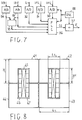
- a regulation characteristic of this type can easily be achieved by the regulation circuit of Figure 6 which constitutes a preferred embodiment of that portion of the control logic 11 of Figure 1 which performs the regulation function.
- the circuit of Figure 6 relates to the case of a resonant converter operating discontinuously, in which the current delivered by the converter increases with the switching frequency; with obvious modifications, it can also be adapted to the case of a resonant converter operating continuously.
- the regulation circuit of Figure 6 comprises essentially an analog multiplier 118, an operational amplifier 18, a voltage-controlled oscillator VCO 19 and a plurality of passive components such as resistors 20, 21, 22, 23, 24, 25, a diode 26, a capacitor 27 and a Zener diode 28.
- the analog multiplier 118 receives as an input a signal IL correlated to the load current and a signal VB correlated to the battery voltage and produces an output signal PL correlated to the load power.
- the inverting input of the amplifier is connected to its output by the feedback resistor 23.
- the signal PL is applied to the non-inverting input of the amplifier through the resistor 20.
- the non-inverting input is also connected to earth through the resistor 24 which has a resistance equal to that of the feedback resistor 23.
- the output of the amplifier is connected to the input of an integrator circuit or low-pass filter formed by the resistor 25 and the capacitor 27.
- the output of the integrator circuit is connected to the input of the VCO 19 which generates a periodic square-wave output signal F with a frequency proportional to the input voltage.
- the frequency F is limited to a maximum value (set by the Zener voltage of the diode 28) corresponding to the maximum power which can be delivered by the fuel cell.
- the rate of increase of F is limited to values permissible for the fuel cell by a suitable selection of the time constant RC of the integrator circuit.
- a reference voltage VREF corresponding to the voltage without load is applied to the non-inverting input of the amplifier through the resistor 22 whilst the measured battery voltage is applied as a signal VB to the inverting input through the resistor 21.
- the Zener diode 28 is superfluous if the maximum voltage A0 delivered by the amplifier imposes on the VCO the output signal frequency equal to the predetermined maximum.
- the one-way low-pass filter formed by the resistor 25, by the capacitor 27 and by the diode 26 can be incorporated in the feedback circuit of the amplifier.
- a plurality of analog/digital converters 30, 31, 32, 33, 34 convert analog signals relating to cell voltage VFC, cell current IFC, load current IL, battery current IB and battery voltage VB, respectively, into corresponding digital data.
- a programmable memory 35 to which the digital data corresponding to the working conditions of the battery are addressed outputs a code indicative of the charge condition.
- a programmable logic device PLC 36 which may also consist of a standard microprocessor for industrial use receives, as inputs, the codes representative of the voltage and current output by the fuel cell, defines what the working condition of the fuel cell should be in dependence on the load current IL and the charge condition of the battery, and outputs a control code CC which is applied as an input to a controlled frequency divider 37.
- the frequency divider is timed by a periodic signal of predetermined frequency generated by an oscillator 38 and produces an output signal F with a frequency equal to the switching frequency which is imposed on the quasi-resonant converter.
- the diagram of Figure 7 represents a regulation system with a feedback loop since it provides for the use of the signals VFC and IFC for the measurement of the power actually delivered by the fuel cell and its comparison with the power set and the correction of any error.
- a lower limit for the power delivered for example, of 20% of the maximum power and corresponding to the mean power taken up by the service equipment of the electric vehicle.
- this can be achieved, for example, by the connection of the input of the VCO 19 to a diode 52 the anode of which is connected to a voltage supply +V2 of suitable value.
- the transformer 5 should have insulation which enables it to withstand, with due safety margins, the primary voltage which is applied thereto as a square wave by the converter and which corresponds, in the worst case, to the maximum voltage delivered by the fuel cell (800 volts without a load).
- the dimensions must be such as to prevent saturation of the magnetic circuit at the peak value of the pulsed current imposed by the resonant circuit, which is of the order of 140 A in the primary.
- the losses in the core (owing to hysteresis and stray currents) and in the windings (resistive) have to be kept within limits such as to enable the transformer to be cooled by natural air circulation within an electrical panel housing the entire electronic power system, with an ambient temperature of between -20°C and +50°C.
- the transformer has to be able to operate in a frequency range of between 10 KHz and 50 KHz.
- Figure 8 shows, in section, a preferred embodiment of a transformer which satisfies these requirements, formed with a modular structure from commercially-available magnetic components.
- the transformer comprises a magnetic core formed by four packs 41, 42, 43, 44 of U-shaped ferrite cores juxtaposed to form two parallel cavities for housing primary and secondary windings with generally rectangular turns.
- Each of the packs is formed in turn by a plurality of separate ferrite cores juxtaposed in a direction perpendicular to the plane of the drawing.
- the packs may be clamped and bound together by mechanical ties or, preferably, cemented with epoxy resin with the winding inserted.
- each elementary ferrite core has a width L of 93 mm, a height H of 76 mm, a cavity width L1 of 34 mm and a cavity depth H1 of 48 mm.
- the thickness of the cores is 20 mm.
- Each pack is formed by four cores. A larger number of cores may be used if a greater power is required.
- the winding selected is of the concentric type with two primaries 46, 47 between which the secondary 45 is interposed.
- these are formed with a Litz wire with outer synthetic polyamide paper insulation known commercially as NOMEX, which can withstand temperatures up to 180°C.
Landscapes
- Engineering & Computer Science (AREA)
- Sustainable Energy (AREA)
- Life Sciences & Earth Sciences (AREA)
- Sustainable Development (AREA)
- Chemical Kinetics & Catalysis (AREA)
- Chemical & Material Sciences (AREA)
- Electrochemistry (AREA)
- General Chemical & Material Sciences (AREA)
- Power Engineering (AREA)
- Manufacturing & Machinery (AREA)
- Transportation (AREA)
- Mechanical Engineering (AREA)
- Fuel Cell (AREA)
Priority Applications (1)
| Application Number | Priority Date | Filing Date | Title |
|---|---|---|---|
| EP95830562A EP0782209A1 (de) | 1995-12-29 | 1995-12-29 | Versorgungsanordnung mit Brennstoffzellen und Pufferbatterie für energieautonome Fahrzeug mit elektrischem Antrieb |
Applications Claiming Priority (1)
| Application Number | Priority Date | Filing Date | Title |
|---|---|---|---|
| EP95830562A EP0782209A1 (de) | 1995-12-29 | 1995-12-29 | Versorgungsanordnung mit Brennstoffzellen und Pufferbatterie für energieautonome Fahrzeug mit elektrischem Antrieb |
Publications (1)
| Publication Number | Publication Date |
|---|---|
| EP0782209A1 true EP0782209A1 (de) | 1997-07-02 |
Family
ID=8222099
Family Applications (1)
| Application Number | Title | Priority Date | Filing Date |
|---|---|---|---|
| EP95830562A Ceased EP0782209A1 (de) | 1995-12-29 | 1995-12-29 | Versorgungsanordnung mit Brennstoffzellen und Pufferbatterie für energieautonome Fahrzeug mit elektrischem Antrieb |
Country Status (1)
| Country | Link |
|---|---|
| EP (1) | EP0782209A1 (de) |
Cited By (20)
| Publication number | Priority date | Publication date | Assignee | Title |
|---|---|---|---|---|
| DE19810556C1 (de) * | 1998-03-11 | 1999-11-18 | Fraunhofer Ges Forschung | Brennstoffzelle mit Spannungswandler |
| EP1086847A2 (de) * | 1999-09-21 | 2001-03-28 | Yamaha Hatsudoki Kabushiki Kaisha | Regelungsverfahren für die Stromversorgung eines hybrid-getriebenen bewegten Geräts |
| WO2001037416A2 (en) * | 1999-11-19 | 2001-05-25 | Koninklijke Philips Electronics N.V. | Power supply unit including an inverter |
| DE20017073U1 (de) * | 2000-10-04 | 2002-02-14 | Sachsenring Entwicklungsgesellschaft mbH, 08058 Zwickau | Brennstoffzellensystem |
| GB2371631A (en) * | 2000-11-02 | 2002-07-31 | Ecostar Electric Drive Systems Llc | Method and apparatus for controlling a load-dependant current generating system |
| EP1264727A2 (de) | 2001-06-06 | 2002-12-11 | Honda Giken Kogyo Kabushiki Kaisha | Regelvorrichtung für ein von Brennstoffzellen angetriebenes Fahrzeug |
| EP1273059A1 (de) * | 2000-04-07 | 2003-01-08 | Avista Laboratories Inc. | Brennstoffzellenenergiesystem, gleichstrom-spannungskonverter, brennstoffzellen-energieerzeugungsverfahren und verfahren zur leistungsregelung |
| US6670063B1 (en) * | 1999-06-09 | 2003-12-30 | Honda Giken Kogyo Kabushiki Kaisha | Fuel cell system |
| WO2004025765A1 (en) * | 2002-09-13 | 2004-03-25 | Proton Energy Systems, Inc. | Method and system for balanced control of backup power |
| WO2004105170A1 (en) * | 2003-04-15 | 2004-12-02 | Eidesvik As | Buffer/converter/dumping system between fuel cells and process |
| US6972159B2 (en) | 2001-05-23 | 2005-12-06 | Daimlerchrysler Ag | Fuel cell system |
| US7060379B2 (en) | 2001-10-12 | 2006-06-13 | Proton Energy Systems, Inc. | Method and system for controlling and recovering short duration bridge power to maximize backup power |
| FR2977739A1 (fr) * | 2011-07-06 | 2013-01-11 | Valeo Sys Controle Moteur Sas | Dispositif electrique et systeme d'alimentation correspondant |
| US20140203658A1 (en) * | 2011-06-17 | 2014-07-24 | Kabushiki Kaisha Toyota Jidoshokki | Resonance-type non-contact power supply system |
| FR3014262A1 (fr) * | 2013-12-03 | 2015-06-05 | Renault Sa | Procede et systeme de commande d'un chargeur bidirectionnel pour vehicule automobile. |
| RU2565588C1 (ru) * | 2014-08-12 | 2015-10-20 | Общество с ограниченной ответственностью "Резонвер" | Способ регулирования выходного тока резонансного источника питания сварочной дуги |
| DE102018218324A1 (de) | 2018-10-26 | 2020-04-30 | Audi Ag | Elektrisches Energiesystem mit Brennstoffzellen |
| CN113506897A (zh) * | 2015-09-29 | 2021-10-15 | 智慧能量有限公司 | 燃料电池系统控制器和相关的方法 |
| DE102020110929A1 (de) | 2020-04-22 | 2021-10-28 | Avl Software And Functions Gmbh | Verfahren zur Einprägung eines Signals in eine Brennstoffzellenanordnung |
| DE102020110926A1 (de) | 2020-04-22 | 2021-10-28 | Avl Software And Functions Gmbh | System zur Einprägung eines Signals in eine Brennstoffzellenanordnung |
Citations (7)
| Publication number | Priority date | Publication date | Assignee | Title |
|---|---|---|---|---|
| US3987352A (en) * | 1974-06-10 | 1976-10-19 | Nissan Motor Co., Ltd. | Method of charging storage battery in power supply system having another battery of larger capacity |
| GB1473798A (en) * | 1974-06-03 | 1977-05-18 | Nissan Motor | Power supply system having two different types of batteries and current-limiting circuit for lower ouput battery |
| US4025860A (en) * | 1974-09-14 | 1977-05-24 | Agency Of Industrial Science & Technology | Control system for battery hybrid system |
| US4411967A (en) * | 1981-06-11 | 1983-10-25 | Mitsubishi Denki Kabushiki Kaisha | Cell generating system |
| JPS58218802A (ja) * | 1982-06-11 | 1983-12-20 | Nissan Motor Co Ltd | 燃料電池車両の制御装置 |
| JPS628460A (ja) * | 1985-07-03 | 1987-01-16 | Toshiba Corp | 燃料電池発電システム |
| US4670702A (en) * | 1985-07-16 | 1987-06-02 | Sanyo Electric Co., Ltd. | Controller for fuel cell power system |
-
1995
- 1995-12-29 EP EP95830562A patent/EP0782209A1/de not_active Ceased
Patent Citations (7)
| Publication number | Priority date | Publication date | Assignee | Title |
|---|---|---|---|---|
| GB1473798A (en) * | 1974-06-03 | 1977-05-18 | Nissan Motor | Power supply system having two different types of batteries and current-limiting circuit for lower ouput battery |
| US3987352A (en) * | 1974-06-10 | 1976-10-19 | Nissan Motor Co., Ltd. | Method of charging storage battery in power supply system having another battery of larger capacity |
| US4025860A (en) * | 1974-09-14 | 1977-05-24 | Agency Of Industrial Science & Technology | Control system for battery hybrid system |
| US4411967A (en) * | 1981-06-11 | 1983-10-25 | Mitsubishi Denki Kabushiki Kaisha | Cell generating system |
| JPS58218802A (ja) * | 1982-06-11 | 1983-12-20 | Nissan Motor Co Ltd | 燃料電池車両の制御装置 |
| JPS628460A (ja) * | 1985-07-03 | 1987-01-16 | Toshiba Corp | 燃料電池発電システム |
| US4670702A (en) * | 1985-07-16 | 1987-06-02 | Sanyo Electric Co., Ltd. | Controller for fuel cell power system |
Non-Patent Citations (2)
| Title |
|---|
| PATENT ABSTRACTS OF JAPAN vol. 011, no. 174 (E - 513) 4 June 1987 (1987-06-04) * |
| PATENT ABSTRACTS OF JAPAN vol. 8, no. 73 (M - 287) 5 April 1984 (1984-04-05) * |
Cited By (30)
| Publication number | Priority date | Publication date | Assignee | Title |
|---|---|---|---|---|
| DE19810556C1 (de) * | 1998-03-11 | 1999-11-18 | Fraunhofer Ges Forschung | Brennstoffzelle mit Spannungswandler |
| US6670063B1 (en) * | 1999-06-09 | 2003-12-30 | Honda Giken Kogyo Kabushiki Kaisha | Fuel cell system |
| EP1086847A2 (de) * | 1999-09-21 | 2001-03-28 | Yamaha Hatsudoki Kabushiki Kaisha | Regelungsverfahren für die Stromversorgung eines hybrid-getriebenen bewegten Geräts |
| EP1086847A3 (de) * | 1999-09-21 | 2002-04-03 | Yamaha Hatsudoki Kabushiki Kaisha | Regelungsverfahren für die Stromversorgung eines hybrid-getriebenen bewegten Geräts |
| US6477062B1 (en) | 1999-11-19 | 2002-11-05 | Koninklijke Philips Electronics N.V. | Power supply unit including an inverter |
| WO2001037416A2 (en) * | 1999-11-19 | 2001-05-25 | Koninklijke Philips Electronics N.V. | Power supply unit including an inverter |
| WO2001037416A3 (en) * | 1999-11-19 | 2001-11-01 | Koninkl Philips Electronics Nv | Power supply unit including an inverter |
| EP1273059A4 (de) * | 2000-04-07 | 2007-08-22 | Relion Inc | Brennstoffzellenenergiesystem, gleichstrom-spannungskonverter, brennstoffzellen-energieerzeugungsverfahren und verfahren zur leistungsregelung |
| EP1273059A1 (de) * | 2000-04-07 | 2003-01-08 | Avista Laboratories Inc. | Brennstoffzellenenergiesystem, gleichstrom-spannungskonverter, brennstoffzellen-energieerzeugungsverfahren und verfahren zur leistungsregelung |
| DE20017073U1 (de) * | 2000-10-04 | 2002-02-14 | Sachsenring Entwicklungsgesellschaft mbH, 08058 Zwickau | Brennstoffzellensystem |
| US6452352B1 (en) | 2000-11-02 | 2002-09-17 | Ballard Power Systems Corporation | Method of current interaction in an electric motor drive system having a load-dependent current generating system |
| GB2371631A (en) * | 2000-11-02 | 2002-07-31 | Ecostar Electric Drive Systems Llc | Method and apparatus for controlling a load-dependant current generating system |
| US6972159B2 (en) | 2001-05-23 | 2005-12-06 | Daimlerchrysler Ag | Fuel cell system |
| EP1264727A2 (de) | 2001-06-06 | 2002-12-11 | Honda Giken Kogyo Kabushiki Kaisha | Regelvorrichtung für ein von Brennstoffzellen angetriebenes Fahrzeug |
| EP1264727A3 (de) * | 2001-06-06 | 2005-06-08 | Honda Giken Kogyo Kabushiki Kaisha | Regelvorrichtung für ein von Brennstoffzellen angetriebenes Fahrzeug |
| US7060379B2 (en) | 2001-10-12 | 2006-06-13 | Proton Energy Systems, Inc. | Method and system for controlling and recovering short duration bridge power to maximize backup power |
| US6902837B2 (en) | 2002-09-13 | 2005-06-07 | Proton Energy Systems, Inc. | Method and system for balanced control of backup power |
| US7244524B2 (en) | 2002-09-13 | 2007-07-17 | Proton Energy Systems, Inc. | Method and system for balanced control of backup power |
| WO2004025765A1 (en) * | 2002-09-13 | 2004-03-25 | Proton Energy Systems, Inc. | Method and system for balanced control of backup power |
| WO2004105170A1 (en) * | 2003-04-15 | 2004-12-02 | Eidesvik As | Buffer/converter/dumping system between fuel cells and process |
| US20140203658A1 (en) * | 2011-06-17 | 2014-07-24 | Kabushiki Kaisha Toyota Jidoshokki | Resonance-type non-contact power supply system |
| FR2977739A1 (fr) * | 2011-07-06 | 2013-01-11 | Valeo Sys Controle Moteur Sas | Dispositif electrique et systeme d'alimentation correspondant |
| FR3014262A1 (fr) * | 2013-12-03 | 2015-06-05 | Renault Sa | Procede et systeme de commande d'un chargeur bidirectionnel pour vehicule automobile. |
| RU2565588C1 (ru) * | 2014-08-12 | 2015-10-20 | Общество с ограниченной ответственностью "Резонвер" | Способ регулирования выходного тока резонансного источника питания сварочной дуги |
| CN113506897A (zh) * | 2015-09-29 | 2021-10-15 | 智慧能量有限公司 | 燃料电池系统控制器和相关的方法 |
| CN113506897B (zh) * | 2015-09-29 | 2024-05-14 | 智慧能量有限公司 | 燃料电池系统控制器和相关的方法 |
| DE102018218324A1 (de) | 2018-10-26 | 2020-04-30 | Audi Ag | Elektrisches Energiesystem mit Brennstoffzellen |
| DE102020110929A1 (de) | 2020-04-22 | 2021-10-28 | Avl Software And Functions Gmbh | Verfahren zur Einprägung eines Signals in eine Brennstoffzellenanordnung |
| DE102020110926A1 (de) | 2020-04-22 | 2021-10-28 | Avl Software And Functions Gmbh | System zur Einprägung eines Signals in eine Brennstoffzellenanordnung |
| DE102020110929B4 (de) | 2020-04-22 | 2024-02-08 | Avl Software And Functions Gmbh | Verfahren zur Einprägung eines Signals in eine Brennstoffzellenanordnung |
Similar Documents
| Publication | Publication Date | Title |
|---|---|---|
| EP0782209A1 (de) | Versorgungsanordnung mit Brennstoffzellen und Pufferbatterie für energieautonome Fahrzeug mit elektrischem Antrieb | |
| US5754028A (en) | Charger for electrical energy accumulator | |
| Nguyen et al. | A novel SiC-based multifunctional onboard battery charger for plug-in electric vehicles | |
| Onar et al. | Vehicular integration of wireless power transfer systems and hardware interoperability case studies | |
| CN110289669B (zh) | 对智能电池的交流充电 | |
| Colak et al. | A novel phase-shift control of semibridgeless active rectifier for wireless power transfer | |
| CN101959711B (zh) | 用于电气车辆的快速充电设备 | |
| EP0992811B1 (de) | Vorrichtung und Steuerungsverfahren für Batterie | |
| US8456869B2 (en) | AC/DC converter having isolating transformer with three secondary windings | |
| KR101540018B1 (ko) | 비상용 보조 부하들을 파워링하는 방법, 보조 컨버터 및 그방법에 의한 철도 차량 | |
| US20020186026A1 (en) | Control device for a resonant converter | |
| CN102792548B (zh) | 电池组的充电均衡系统 | |
| US20210044216A1 (en) | A multi-level modular converter | |
| US20110261591A1 (en) | Converter for single-phase and three-phase operation, d.c. voltage supply and battery charger | |
| EP0253345A2 (de) | Induktive Energiekupplung mit konstantem Spannungsausgang | |
| US9780570B2 (en) | Providing a vehicle with electric energy using induction and a rectifier | |
| Hata et al. | Maximum efficiency control of wireless power transfer via magnetic resonant coupling considering dynamics of DC-DC converter for moving electric vehicles | |
| CN112436779B (zh) | 一种电驱动系统、动力总成以及电动汽车 | |
| CN104160605A (zh) | 包括具有谐振隔离级的ac/dc转换器的车辆电池外部装载装置 | |
| Lovison et al. | Secondary-side-only control for high efficiency and desired power with two converters in wireless power transfer systems | |
| Lovison et al. | Secondary-side-only phase-shifting voltage stabilization control with a single converter for WPT systems with constant power load | |
| EP0849111B1 (de) | Versorgungseinheit für ein elektrisches Fahrzeug | |
| KR20190123401A (ko) | 주행 및 회생 제동 전류를 이용한 에너지 하베스팅 방법 및 장치 | |
| Viana et al. | Auxiliary power module elimination in EVs using dual inverter drivetrain | |
| CN116034526A (zh) | 用于机动车辆的电池充电器、相关联的车辆和实施方法 |
Legal Events
| Date | Code | Title | Description |
|---|---|---|---|
| PUAI | Public reference made under article 153(3) epc to a published international application that has entered the european phase |
Free format text: ORIGINAL CODE: 0009012 |
|
| AK | Designated contracting states |
Kind code of ref document: A1 Designated state(s): BE DE FR GB IT NL |
|
| 17P | Request for examination filed |
Effective date: 19970919 |
|
| GRAG | Despatch of communication of intention to grant |
Free format text: ORIGINAL CODE: EPIDOS AGRA |
|
| 17Q | First examination report despatched |
Effective date: 19981105 |
|
| STAA | Information on the status of an ep patent application or granted ep patent |
Free format text: STATUS: THE APPLICATION HAS BEEN REFUSED |
|
| 18R | Application refused |
Effective date: 19990430 |