EP0781937B1 - Procédé de fixation par collage de garnitures de friction sur un disque de support - Google Patents
Procédé de fixation par collage de garnitures de friction sur un disque de support Download PDFInfo
- Publication number
- EP0781937B1 EP0781937B1 EP96120338A EP96120338A EP0781937B1 EP 0781937 B1 EP0781937 B1 EP 0781937B1 EP 96120338 A EP96120338 A EP 96120338A EP 96120338 A EP96120338 A EP 96120338A EP 0781937 B1 EP0781937 B1 EP 0781937B1
- Authority
- EP
- European Patent Office
- Prior art keywords
- heating means
- disc
- plate
- heating
- friction
- Prior art date
- Legal status (The legal status is an assumption and is not a legal conclusion. Google has not performed a legal analysis and makes no representation as to the accuracy of the status listed.)
- Expired - Lifetime
Links
- 238000000034 method Methods 0.000 title claims description 25
- 238000010438 heat treatment Methods 0.000 claims description 84
- 238000001816 cooling Methods 0.000 claims description 12
- 238000004026 adhesive bonding Methods 0.000 claims description 5
- 239000004831 Hot glue Substances 0.000 claims description 3
- 239000012530 fluid Substances 0.000 claims description 2
- 239000002826 coolant Substances 0.000 claims 1
- 238000006073 displacement reaction Methods 0.000 claims 1
- 239000003292 glue Substances 0.000 description 11
- 239000002184 metal Substances 0.000 description 10
- 239000000853 adhesive Substances 0.000 description 5
- 230000001070 adhesive effect Effects 0.000 description 5
- 238000006243 chemical reaction Methods 0.000 description 3
- 230000000694 effects Effects 0.000 description 3
- 230000002093 peripheral effect Effects 0.000 description 3
- 229920001187 thermosetting polymer Polymers 0.000 description 3
- 210000002105 tongue Anatomy 0.000 description 3
- 230000015556 catabolic process Effects 0.000 description 2
- 238000006731 degradation reaction Methods 0.000 description 2
- 239000000463 material Substances 0.000 description 2
- 230000000750 progressive effect Effects 0.000 description 2
- 239000006096 absorbing agent Substances 0.000 description 1
- 239000002253 acid Substances 0.000 description 1
- 230000015572 biosynthetic process Effects 0.000 description 1
- 239000012809 cooling fluid Substances 0.000 description 1
- 239000010431 corundum Substances 0.000 description 1
- 229910052593 corundum Inorganic materials 0.000 description 1
- 230000008021 deposition Effects 0.000 description 1
- 238000001914 filtration Methods 0.000 description 1
- 239000002783 friction material Substances 0.000 description 1
- 230000006698 induction Effects 0.000 description 1
- 239000007788 liquid Substances 0.000 description 1
- ISWSIDIOOBJBQZ-UHFFFAOYSA-N phenol group Chemical group C1(=CC=CC=C1)O ISWSIDIOOBJBQZ-UHFFFAOYSA-N 0.000 description 1
- 238000005554 pickling Methods 0.000 description 1
- 238000006116 polymerization reaction Methods 0.000 description 1
- 238000003825 pressing Methods 0.000 description 1
- 230000035939 shock Effects 0.000 description 1
- 238000002791 soaking Methods 0.000 description 1
- 239000000126 substance Substances 0.000 description 1
- 238000010792 warming Methods 0.000 description 1
Images

Classifications
-
- F—MECHANICAL ENGINEERING; LIGHTING; HEATING; WEAPONS; BLASTING
- F16—ENGINEERING ELEMENTS AND UNITS; GENERAL MEASURES FOR PRODUCING AND MAINTAINING EFFECTIVE FUNCTIONING OF MACHINES OR INSTALLATIONS; THERMAL INSULATION IN GENERAL
- F16D—COUPLINGS FOR TRANSMITTING ROTATION; CLUTCHES; BRAKES
- F16D69/00—Friction linings; Attachment thereof; Selection of coacting friction substances or surfaces
- F16D69/04—Attachment of linings
-
- F—MECHANICAL ENGINEERING; LIGHTING; HEATING; WEAPONS; BLASTING
- F16—ENGINEERING ELEMENTS AND UNITS; GENERAL MEASURES FOR PRODUCING AND MAINTAINING EFFECTIVE FUNCTIONING OF MACHINES OR INSTALLATIONS; THERMAL INSULATION IN GENERAL
- F16D—COUPLINGS FOR TRANSMITTING ROTATION; CLUTCHES; BRAKES
- F16D13/00—Friction clutches
- F16D13/58—Details
- F16D13/60—Clutching elements
- F16D13/64—Clutch-plates; Clutch-lamellae
- F16D2013/642—Clutch-plates; Clutch-lamellae with resilient attachment of frictions rings or linings to their supporting discs or plates for allowing limited axial displacement of these rings or linings
-
- F—MECHANICAL ENGINEERING; LIGHTING; HEATING; WEAPONS; BLASTING
- F16—ENGINEERING ELEMENTS AND UNITS; GENERAL MEASURES FOR PRODUCING AND MAINTAINING EFFECTIVE FUNCTIONING OF MACHINES OR INSTALLATIONS; THERMAL INSULATION IN GENERAL
- F16D—COUPLINGS FOR TRANSMITTING ROTATION; CLUTCHES; BRAKES
- F16D69/00—Friction linings; Attachment thereof; Selection of coacting friction substances or surfaces
- F16D69/04—Attachment of linings
- F16D2069/0425—Attachment methods or devices
- F16D2069/045—Bonding
- F16D2069/0466—Bonding chemical, e.g. using adhesives, vulcanising
- F16D2069/0475—Bonding chemical, e.g. using adhesives, vulcanising comprising thermal treatment
-
- F—MECHANICAL ENGINEERING; LIGHTING; HEATING; WEAPONS; BLASTING
- F16—ENGINEERING ELEMENTS AND UNITS; GENERAL MEASURES FOR PRODUCING AND MAINTAINING EFFECTIVE FUNCTIONING OF MACHINES OR INSTALLATIONS; THERMAL INSULATION IN GENERAL
- F16D—COUPLINGS FOR TRANSMITTING ROTATION; CLUTCHES; BRAKES
- F16D69/00—Friction linings; Attachment thereof; Selection of coacting friction substances or surfaces
- F16D69/04—Attachment of linings
- F16D2069/0425—Attachment methods or devices
- F16D2069/0491—Tools, machines, processes
Definitions
- the present invention relates to a method of fixing by bonding friction linings on either side of a disc metallic support, in particular for a motor vehicle, such as described for example in document FR-A-2 164 139.
- hot glue is applied to the metal disc or on the friction linings, then put in place the friction linings in a press when mounting under pressure said disc and said friction linings between an abutment and an abutment carried respectively by a upper pressure plate and a lower pressure plate belonging to the press and finally heating said disc using first means of heating.
- the heating means are means of induction heating allowing rapid heating of the disc.
- This process does not subject the friction material to high heating.
- the operation only lasts a few seconds.
- a method of the above-mentioned type is characterized in that the stop and the counter-stop belong to second means for heating the friction linings and what is heated faster, using the first means heater, the metal support disc that the linings friction using the second heating means.
- the temperature reached by the first and second heating means can be the same, but we put in action the second heating means with a shift in the time (deferred in time), for example 30 seconds.
- the support disc is heated faster. temperature rise being faster than that of the linings friction.
- the glue hardens before the friction linings dilate.
- the temperature reached by the second means of heating, to heat the friction linings is lower than the temperature reached by the first means of heating to heat the support disc. It all depends on applications and in particular the nature of the adhesive.
- the temperature difference being for example 40 °.
- thermosetting type an adhesive of the thermosetting type is used.
- the heating time depends on the applications and in particular on the temperature reached by the heating means.
- thermosetting adhesive you need for example 1 hour at 150 ° and 5 minutes at 200 ° to properly control the process lift-off.
- the friction linings also being heated as a whole and not at risk of being damaged by the temperature reached, the temperature between the two heating means, so that we control the glue heating and differential expansions between fittings and disc. Then let cool or not the whole stuck in the press.
- the linings can be stuck in spots friction on their associated disc.
- the glue dots are advantageously deposited at the places where we used to fix rivets before friction linings on the metal disc.
- the second heating means surround the first heating means in being of the annular type.
- These second heating means can be provided with channels for their cooling.
- the process according to the invention is particularly advantageous in the case where the friction disc has tripod blades having large central range areas.
- a clutch friction has a input part 16,131,132 coupled to an output part 3.
- the entry part 16,131,132 is suitable for being clamped between the pressure and reaction plates of a clutch integral in rotation, possibly resiliently when the reaction plate is in two parts belonging to a steering wheel shock absorber, a driving shaft (the end of the crankshaft in the application to a motor vehicle), while the outlet part 3 usually consists of a splined hub internally for its rotational connection to a driven shaft (the input shaft of the gearbox in the case of a application to a motor vehicle).
- the input element 16,131,132 can be coupled so rigid at the output element 3, for example being fixed by riveting on a web or flange secured to the hub 3.
- the input element is resiliently coupled to the element output 3.
- the input element 16,131,132 is integral with two guide washers 1,2 arranged on the side and other of a veil 4 integral in rotation, possibly after adjustment of an angular play with intervention of means of engagement with play, of the hub 3 constituting the output element.
- Circumference springs 9 are housed in housing, most often windows, facing each other in the guide washers 1,2 and in the web 4. Means elastics with axial action 20 also intervene between the guide washers 1,2 and the web 4.
- the clutch constitutes a cut-off and starting device between the engine and the gearbox speeds and filters vibrations in the chain kinematics from the motor shaft to the wheel shafts.
- Another function is to ensure the comfort of passengers by avoiding any brutality when re-engaging the clutch.
- the input element 3,132,133 is of the progressive type in being elastic. In the "clutch disengaged" state, the thickness of said input element is larger than in “clutch engaged” state.
- this input element comprises a disc of metal support 16 comprising a central part 16 and a peripheral part divided into elastic radial blades suitable for fixing friction linings 131,132.
- the blades have zones offset axially with respect to the central part 16 and used for fixing the linings of friction 131.132.
- This central part 16 is for example (FIG. 1) fixed to the guide washers 1,2 using the balusters 8 connecting between they to fixing the guide washers 1,2 and through for do this, with circumferential clearance, of the openings 7 of the web 4.
- the friction linings 131,132 are fixed usually using rivets 47.
- rivets 47 For more details, see refer for example to document EP-A-0 579 554.
- the disadvantage of fixing by riveting is a increased thickness of the linings 131,132 so that a sufficient material thickness exists between the outer face of the friction lining and rivet head 47.
- This one can present for example, figure 2, to its outer periphery, alternating blades 971 and tongues 972,973 in radial orientation.
- the 971 blades are of the tripod type and have a zone central range 922 offset axially from the part central 16 of disk 16 and two peripheral areas of range 923 arranged on either side of the central zone 922 while being axially offset from said central area.
- Oblique folds 921 with respect to the axis of symmetry radial of the blade 971, connect the central zone 922 to the zones range devices 923
- a tangential fold 924 perpendicular to the radial axis of symmetry of the blade 971, connects the central zone 922 to the central part of the disc 16 having holes 119 for fixing it by riveting to the guide washer 1 of the figure 1.
- the central area 922 is increased thanks to the formation of a tongue 925 formed by a U-shaped slot 926 affecting the fold 924.
- the central zone 922 is used for fixing friction lining 132 intended to come into contact with the clutch pressure plate.
- peripheral areas of range 923 are suitable for coming into contact with the other friction lining 131 being here in the plane of the central part of the disc 16.
- the tabs 972,973 have a main part in the plan of the central part of the disc 16 and are used for fixing the other lining 131 intended to come into contact with the plate less deformed than the pressure plate under the effect of heat.
- Slots 324 separate the tabs 972,973 from the blades 971.
- the tabs have at least one range 942,932 additional axially offset from their part main contact with the other friction lining 132.
- an additional range 944 can be formed directed axially towards the lining 132 by means of a slot 946 and a tangential fold.
- This pickling can be mechanical, for example corundum, or chemical, for example soaking in a acid bath.
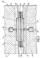
- This press has an upper pressure plate 41 and a lower pressure plate 42 mounted axially movable one by compared to each other.
- the pressure plates 41,42 have respectively a stop 31 and a counter-stop 32 for tightening the friction lining assembly 131,132 and metal disc of support 16, sandwiched between said linings.
- This stop 31 and this counter-stop 32 are provided with means for position the friction linings 131,132.
- This stop 31 or this counter-stop 32 can also be provided with means for prepositioning the disk 16.
- one of the pressure plates 41,42 can be shaped to preposition said disc.
- the adhesive is for example thermosetting, here of the type phenolic, and is suitable for undergoing polymerization. She sticks so hot.
- the method of fixing by gluing the friction linings 131,132 on either side of the disc support metal 16, in particular for clutch friction of motor vehicle includes a step in which hot glue on said metal disc or on the friction linings 131,132, then a step in which installs the friction linings 131,132 in the press 30 by mounting said disc and said linings under pressure friction between the stop 31 and the counter stop 32 carried respectively by the upper pressure plate 41 and the lower pressure plate 42 belonging to the press, and finally said disc is heated using first heating means 51.52.
- This process is characterized in that the stop 31 and the butted 32 belong to second heating means to heat the friction linings 131,132 and in that one heats faster, using the first heating means 51,52 the metal support disc 16 that the linings of friction 131.132 using the second heating means 31.32 ..
- This heating operation leading to fixing by bonding of the linings 131, 132 on the disc 16, has a duration by example of 5 min at 200 °.
- a cooling step is carried out, always keeping the friction linings under pressure and the disc.
- the cooling is carried out at outside the press.
- This deposition is carried out using a nozzle and is carried out at point 100 previously used for fixing the seals 131,132 to disc 16 by rivets 47.
- the disc 16 is flattened because it is compressed between the stops 31 and 32 via the fittings 131,132.
- the temperature reached by the support disc 16 can be for example 200 ° and be identical to that reached by the friction linings 131,132. Alternatively the temperature reached by the friction linings 131,132 can be lower than that reached by the support disc 16.
- the duration of the heating is explained in particular by the fact that it it takes a while to raise the temperature of the toppings friction 131,132 which are thermally insulating. Besides that allows better control of the gradual warming up of heating means.
- the difference in temperature rise of the means of heating allows better control of the bonding process by so that the glue hardens before the trim 131,132 dilate.
- Heating can be achieved for example by conduction.
- the first heating means 51, 52 include heating plates 51,52, here circular, carried respectively by the upper pressure plate 41 and the pressure plate lower 42. These heating plates 51, 52 are subjected to the action each of an actuator 60 allowing said plates 51, 52 to come into contact with the upper and lower faces of the disc 16. Heating of the disc 16 can be achieved by conduction. Each actuator 60 and carried by the plate of pressure 41.42 concerned.
- the second heating means 31, 32 consist here in pressure heating blocks, fixedly mounted on their associated pressure plates 41,42. They surround the first heating means 51, 52 being of annular shape.
- Each plate 41.42 is hollowed out centrally at 61.62 for that the plates 51 and 52 can move axially when the linings 131; 132 and the disc are clamped between the stop 31 and the 32 heating buttress.
- the second heating means 31, 32 can be heated electrically just like the first heating means 51,52, so that as soon as you cut the electrical current, the heating is interrupted.
- the second heating means 31.32 can act temporally deferred. Alternatively the rise in temperature of the second heating means is slower than is not that of the first means of heating.
- These second heating means have for example, in within them, channels 70 allowing rapid cooling of seals 131,132 by circulation of a cooling fluid in the channels 70.
- the fluid may be of a gaseous nature or liquid.
- the heating means are isolated of the mass of the plates 41.42, which allows further control more finely the collage.
- the present invention is not limited to the example of embodiment described, in particular the tripod blades may have a different shape, for example one of the shapes described in document EP-A-0 579 554, obviously knowing that the holes for the passage of the rivets constitute points where bonding is carried out, said holes being eliminated. So the blades can all be of the tripod type and, in FIG. 2, this only as an example we have represented two types different from tabs 972,973, the disc 16 generally being equipped with only one type of tongue.
- the invention applies to any type of progressive support disc, the blades may not be tripod type. It is possible to vary the pressure between heating and cooling operations.
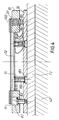
- the heating means can be arranged so different especially at the bottom of the press as shown in figure 4.
- a plate 81 axially movable, is associated with the counter stop 32 consisting of an electrically heated plate extending below the lower part 52 of the first heating means 51, 52.
- the plate 81 is axially movable by means of balusters 82 screwed into plate 32 electrically powered for heating of the lining 131 via the thermally conductive plate 81, here metallic.
- the heads of the balusters 82 are mounted in counterbores 83 of the plate 81 serving as a support for the friction lining 131.
- the plate 81 also has blind holes 84 for mounting of return springs 85, here coil springs, bearing on the heating plate 32 and the bottom of the hole blind 84.
- return springs 85 here coil springs
- the springs 85 and the balusters 82 are distributed regularly circumferentially alternately.
- the first heating means 51, 52 comprise a plate heater 52 electrically powered and axially movable using balusters 182 and return springs 91 in the same way than plate 81. More precisely, the balusters 182 have a head mounted in a counterbore 183 of the plate 32 and a blossoming foot for fixing the baluster 183 to the plate 52, here thin for allow rapid heating of the disk 16.
- the plate 52 is electrically powered.
- the plate 81 thicker than the plate 52, surrounds said tray 52.
- the balusters 82, 182 are head to tail mounted, the heads of the columns 82, 182 limiting the axial movement of plate 81 and plate 52 respectively by cooperation with the bottom of the counterbores 83, 183.
- the plate 81 raises the friction linings 131, 132 as well as the support disc 16 as soon as one opens the hurry. This creates a thermal conduction break between the linings 131, 132 and the second heating means proper 31, 32 and between disc 16 and the first heating means 51, 52, the axial movement of the plate 52 being lower than that of plate 81.
- a thermally insulating plate 72 is associated with the plate 32 to isolate it from the lower part of the hurry.
- each heating means can control the rise in temperature of each heating means by varying by example the intensity of the electric current.
- the materials of heating means may be different. We can play on the thickness of the heating means. Many parameters therefore allow the support disc to be heated more quickly.
Landscapes
- Engineering & Computer Science (AREA)
- General Engineering & Computer Science (AREA)
- Mechanical Engineering (AREA)
- Braking Arrangements (AREA)
- Mechanical Operated Clutches (AREA)
Description
- la figure 1 est une vue en coupe axiale d'une friction d'embrayage équipée d'un disque de support et de deux garnitures de friction fixées par rivetage sur ledit disque ;
- la figure 2 est une vue partielle de la périphérie externe d'un disque de support sur lequel sont propres à être fixées par collage des garnitures de friction ;
- la figure 3 est une vue schématique d'une presse permettant d'appliquer une pression et le chauffage selon le procédé de la présente invention ;
- la figure 4 est une demi-vue analogue à la figure 3 pour un autre exemple de réalisation.
Claims (14)
- Procédé de fixation par collage de garnitures de friction (131,132) de part et d'autre d'un disque métallique de support (16); notamment pour friction d'embrayage de véhicule automobile, dans lequel on dépose de la colle collant à chaud sur ledit disque métallique (16) ou sur les garnitures de friction (131,132), puis on met en place les garnitures de friction (131,132) dans une presse (30) en montant sous pression ledit disque et lesdites garnitures de friction entre une butée (31) et une contrebutée (32) portées respectivement par un plateau de pression supérieur (41) et un plateau de pression inférieur (42) appartenant à la presse (30), et on chauffe ledit disque (16) à l'aide de premiers moyens de chauffage (51,52), caractérisé en ce que la butée (31) et la contrebutée (32) appartiennent à des second moyens de chauffage des garnitures de friction (131,132), et en ce que l'on chauffe plus rapidement, à l'aide des premiers moyens de chauffage (51,52), le disque métallique de support (16) que les garnitures de friction (131,132) à l'aide des seconds moyens de chauffage (51,52)
- Procédé selon la revendication 1, caractérisé en ce que les seconds moyens de chauffage (31,32) entourent les premiers moyens de chauffage (51,52).
- Procédé selon la revendication 1 ou 2, caractérisé en ce que les seconds moyens de chauffage (31,32) sont pourvus de moyens de refroidissement (70).
- Procédé selon la revendication 3, caractérisé en ce que lesdits moyens de refroidissement (70) consistent en des canaux permettant le passage d'un fluide de refroidissement.
- Procédé selon l'une quelconque des revendications 1 à 5, caractérisé en ce que les seconds moyens de chauffage (31,32) sont de nature électrique.
- Procédé selon l'une quelconque des revendications 1 à 5, caractérisé en ce que les premiers moyens de chauffage (51,52) comportent des plateaux chauffants (51,52) portés à mobilité axiale respectivement par le plateau de pression supérieur (41) et le plateau de pression inférieur (42).
- Procédé selon la revendication 6, caractérisé en ce que lesdits plateaux (51,52) sont montés mobiles par l'intermédiaire d'actionneurs (60).
- Procédé selon la revendication 7, caractérisé en ce que les plateaux de pression inférieur (42) et supérieur (41) sont creusés pour montage des premiers moyens de chauffage (51,52).
- Procédé selon l'une quelconque des revendications 1 à 9, caractérisé en ce que les premiers moyens de chauffage (51,52) et les seconds moyens de chauffage (31,32) sont montés sur leurs plateaux de pression respectifs (41,42) par l'intermédiaire de plaques thermiquement isolantes (71,72).
- Procédé selon l'une quelconque des revendications 3 à 9, caractérisé en ce qu'une plaque mobile axialement (81) est associée aux seconds moyens de chauffage (31,32).
- Procédé selon la revendication 10, caractérisé en ce que les seconds moyens de chauffage (31,32) comportent un second plateau (32) s'étendant en-dessous d'un premier plateau (52) appartenant aux premiers moyens de chauffage (51,52).
- Procédé selon la revendication 11, caractérisé en ce que la plaque (81) et ledit premier plateau (52) sont montés mobiles axialement à l'aide de colonnettes (82,182) associées au deuxième plateau (32) à l'encontre de ressorts de rappel (85,91).
- Procédé selon l'une quelconque des revendications 1 à 12, caractérisé en ce que les seconds moyens de chauffage (31,32) interviennent de manière différée dans le temps.
- Procédé selon l'une quelconque des revendications 1 à 12, caractérisé en ce que la montée en température des seconds moyens de chauffage (31,32) est moins rapide que celle des premiers moyens de chauffages (51,52).
Applications Claiming Priority (2)
| Application Number | Priority Date | Filing Date | Title |
|---|---|---|---|
| FR9515520A FR2743127B1 (fr) | 1995-12-27 | 1995-12-27 | Procede de fixation par collage de garnitures de friction sur un disque de support |
| FR9515520 | 1995-12-27 |
Publications (2)
| Publication Number | Publication Date |
|---|---|
| EP0781937A1 EP0781937A1 (fr) | 1997-07-02 |
| EP0781937B1 true EP0781937B1 (fr) | 2000-06-28 |
Family
ID=9485978
Family Applications (1)
| Application Number | Title | Priority Date | Filing Date |
|---|---|---|---|
| EP96120338A Expired - Lifetime EP0781937B1 (fr) | 1995-12-27 | 1996-12-18 | Procédé de fixation par collage de garnitures de friction sur un disque de support |
Country Status (5)
| Country | Link |
|---|---|
| US (1) | US5810969A (fr) |
| EP (1) | EP0781937B1 (fr) |
| DE (1) | DE69609045T2 (fr) |
| ES (1) | ES2150628T3 (fr) |
| FR (1) | FR2743127B1 (fr) |
Cited By (1)
| Publication number | Priority date | Publication date | Assignee | Title |
|---|---|---|---|---|
| CN107605898A (zh) * | 2017-09-15 | 2018-01-19 | 深圳天珑无线科技有限公司 | 一种粘胶装配方法 |
Families Citing this family (12)
| Publication number | Priority date | Publication date | Assignee | Title |
|---|---|---|---|---|
| US6116316A (en) * | 1996-05-13 | 2000-09-12 | Toolex Alpha Ab | Device for bending a flat, round disc element |
| US6245180B1 (en) * | 1999-04-02 | 2001-06-12 | Midwest Brake Bond Company | Methods for bending brake lining material and for forming a lined brake shoe |
| FR2817005B1 (fr) * | 2000-11-20 | 2002-12-27 | Valeo | Dispositif de fixation par collage de garnitures de friction et procede de fixation |
| KR100712088B1 (ko) * | 2002-05-27 | 2007-05-02 | 한라공조주식회사 | 클러치 풀리의 마찰재 접착장치 및 방법 |
| EP1876368B1 (fr) * | 2006-07-08 | 2010-12-15 | ZF Friedrichshafen AG | Procédé de fabrication d'une disque d'embrayage et une disque d'embrayage |
| DE102008040962A1 (de) | 2007-09-13 | 2009-03-19 | Zf Friedrichshafen Ag | Verfahren zum Herstellen einer Verbindung zwischen einer Kupplungsscheibe und einem Reibbelag und Kupplungsscheibe |
| DE102008001259A1 (de) | 2008-04-18 | 2009-10-22 | Zf Friedrichshafen Ag | Kupplungsscheibe, insbesondere für eine Kraftfahrzeugkupplung |
| CN104235135A (zh) * | 2014-09-03 | 2014-12-24 | 苏州震昇机电设备有限公司 | 一种扁带粘接机 |
| FR3044058B1 (fr) | 2015-11-25 | 2017-12-22 | Valeo Materiaux De Friction | Garniture de friction comprenant une resine melamine etherifiee |
| CN115451048B (zh) * | 2022-08-16 | 2024-07-19 | 勃兰姆斯基摩擦材料(湖州)有限公司 | 一种大型锻压机用摩擦片粘结工艺及专用夹具 |
| CN116696906B (zh) * | 2023-05-04 | 2026-04-14 | 荣成歌尔科技有限公司 | 粘接设备 |
| CN121557182A (zh) * | 2026-01-23 | 2026-02-24 | 中北大学 | 复杂深孔内表面自动化贴装装备及方法 |
Family Cites Families (8)
| Publication number | Priority date | Publication date | Assignee | Title |
|---|---|---|---|---|
| DE1575933B2 (de) * | 1966-08-26 | 1970-09-17 | Jurid Werke Gmbh, 2056 Glinde | Reibscheibe für Bremsen und Kupplungen |
| US3740512A (en) | 1971-12-06 | 1973-06-19 | Dab Ind Inc | Method for adhering friction material to ring-like element |
| US3798403A (en) * | 1971-12-06 | 1974-03-19 | Dab Ind Inc | Apparatus for adhering friction material to ring-like element |
| AT397490B (de) * | 1987-12-15 | 1994-04-25 | Leinweber Anstalt Ing Joh | Vorrichtung zum pressen von gekrümmten bremsbelägen |
| DE3907443C2 (de) * | 1989-03-08 | 1994-02-24 | Miba Frictec Gmbh | Verfahren und Vorrichtung zum Herstellen einer Reiblamelle |
| US5091041A (en) * | 1989-03-22 | 1992-02-25 | Eaton Corporation | Bonding apparatus for bonding friction material |
| US5452783A (en) | 1992-07-15 | 1995-09-26 | Valeo | Liner support disc, especially for a motor vehicle clutch |
| JP2904244B2 (ja) * | 1992-08-31 | 1999-06-14 | トヨタ自動車株式会社 | ディスクブレーキ用摩擦パッドの製造方法 |
-
1995
- 1995-12-27 FR FR9515520A patent/FR2743127B1/fr not_active Expired - Fee Related
-
1996
- 1996-12-18 EP EP96120338A patent/EP0781937B1/fr not_active Expired - Lifetime
- 1996-12-18 DE DE69609045T patent/DE69609045T2/de not_active Expired - Lifetime
- 1996-12-18 ES ES96120338T patent/ES2150628T3/es not_active Expired - Lifetime
- 1996-12-23 US US08/772,496 patent/US5810969A/en not_active Expired - Fee Related
Cited By (1)
| Publication number | Priority date | Publication date | Assignee | Title |
|---|---|---|---|---|
| CN107605898A (zh) * | 2017-09-15 | 2018-01-19 | 深圳天珑无线科技有限公司 | 一种粘胶装配方法 |
Also Published As
| Publication number | Publication date |
|---|---|
| DE69609045T2 (de) | 2001-03-08 |
| FR2743127B1 (fr) | 1998-02-13 |
| ES2150628T3 (es) | 2000-12-01 |
| US5810969A (en) | 1998-09-22 |
| DE69609045D1 (de) | 2000-08-03 |
| EP0781937A1 (fr) | 1997-07-02 |
| FR2743127A1 (fr) | 1997-07-04 |
Similar Documents
| Publication | Publication Date | Title |
|---|---|---|
| EP0781937B1 (fr) | Procédé de fixation par collage de garnitures de friction sur un disque de support | |
| EP0213009B1 (fr) | Mécanisme d'embrayage à diaphragme,notamment pour véhicule automobile | |
| EP0228310B1 (fr) | Mécanisme d'embrayage à rondelle Belleville notamment pour véhicule automobile, et embrayage correspondant | |
| FR2546593A2 (fr) | Embrayage a couronne de demarreur et cible d'allumage, notamment pour vehicule automobile | |
| WO1998054477A1 (fr) | Mecanisme d'embrayage pour embrayage a friction | |
| EP0166640B1 (fr) | Disque de friction d'embrayage de type progressif à construction simplifiée | |
| FR2526102A1 (fr) | Embrayage a plateau de reaction en deux parties, notamment pour vehicule automobile | |
| WO2013104869A1 (fr) | Procédé de réalisation d'une garniture de friction d'embrayage | |
| EP0914566B1 (fr) | Mecanisme d'embrayage pour embrayage a friction a faible effort de debrayage | |
| WO2015155435A1 (fr) | Procede de traitement perfectionne d'une surface d'un element de friction | |
| EP0735290B1 (fr) | Mécanisme d'embrayage à diaphragme, notamment pour véhicule automobile | |
| EP2089635A2 (fr) | Disque de friction d'embrayage | |
| EP0975882B1 (fr) | Mecanisme d'embrayage, notamment pour vehicule automobile | |
| FR2688840A1 (fr) | Diaphragme pour module d'embrayage et son module d'embrayage, notamment pour vehicules automobiles. | |
| EP0948720B1 (fr) | Double volant amortisseur de torsion a rondelles d'etancheite, notamment pour vehicules automobiles | |
| WO1995034766A1 (fr) | Couvercle monobloc pour mecanisme d'embrayage et mecanisme d'embrayage comportant un tel couvercle | |
| FR2783580A1 (fr) | Mecanisme d'embrayage, notamment pour vehicule automobile | |
| EP0360650A1 (fr) | Butée de débrayage, notamment pour véhicules automobiles | |
| FR2741917A1 (fr) | Module d'embrayage comportant des moyens perfectionnes de fixation de son couvercle sur le plateau de reaction | |
| WO2014053738A1 (fr) | Disque de friction d'embrayage | |
| EP0797017A1 (fr) | Disque à garnitures de friction pour embrayage mécanique | |
| FR2688557A1 (fr) | Mecanisme d'embrayage a diaphragme, notamment pour vehicule automobile et son procede de fabrication. | |
| FR2804184A1 (fr) | Embrayage a friction comportant un plateau de reaction portant un rotor d'une machine electrique tournante, notamment pour vehicule automobile, l'encombrement radial dudit embrayage etant reduit | |
| EP0916034B1 (fr) | Liaison volant-couvercle d'un embrayage a friction | |
| FR2732736A1 (fr) | Mecanisme d'embrayage a couvercle en deux parties pour embrayage a diaphragme, notamment pour vehicule automobile |
Legal Events
| Date | Code | Title | Description |
|---|---|---|---|
| PUAI | Public reference made under article 153(3) epc to a published international application that has entered the european phase |
Free format text: ORIGINAL CODE: 0009012 |
|
| AK | Designated contracting states |
Kind code of ref document: A1 Designated state(s): DE ES GB IT |
|
| 17P | Request for examination filed |
Effective date: 19980123 |
|
| GRAG | Despatch of communication of intention to grant |
Free format text: ORIGINAL CODE: EPIDOS AGRA |
|
| 17Q | First examination report despatched |
Effective date: 19990916 |
|
| GRAG | Despatch of communication of intention to grant |
Free format text: ORIGINAL CODE: EPIDOS AGRA |
|
| GRAH | Despatch of communication of intention to grant a patent |
Free format text: ORIGINAL CODE: EPIDOS IGRA |
|
| GRAH | Despatch of communication of intention to grant a patent |
Free format text: ORIGINAL CODE: EPIDOS IGRA |
|
| GRAA | (expected) grant |
Free format text: ORIGINAL CODE: 0009210 |
|
| AK | Designated contracting states |
Kind code of ref document: B1 Designated state(s): DE ES GB IT |
|
| REF | Corresponds to: |
Ref document number: 69609045 Country of ref document: DE Date of ref document: 20000803 |
|
| GBT | Gb: translation of ep patent filed (gb section 77(6)(a)/1977) |
Effective date: 20000717 |
|
| ITF | It: translation for a ep patent filed | ||
| REG | Reference to a national code |
Ref country code: ES Ref legal event code: FG2A Ref document number: 2150628 Country of ref document: ES Kind code of ref document: T3 |
|
| PLBE | No opposition filed within time limit |
Free format text: ORIGINAL CODE: 0009261 |
|
| STAA | Information on the status of an ep patent application or granted ep patent |
Free format text: STATUS: NO OPPOSITION FILED WITHIN TIME LIMIT |
|
| 26N | No opposition filed | ||
| REG | Reference to a national code |
Ref country code: GB Ref legal event code: IF02 |
|
| PGFP | Annual fee paid to national office [announced via postgrant information from national office to epo] |
Ref country code: ES Payment date: 20071218 Year of fee payment: 12 |
|
| PGFP | Annual fee paid to national office [announced via postgrant information from national office to epo] |
Ref country code: IT Payment date: 20071221 Year of fee payment: 12 |
|
| PGFP | Annual fee paid to national office [announced via postgrant information from national office to epo] |
Ref country code: GB Payment date: 20071214 Year of fee payment: 12 |
|
| GBPC | Gb: european patent ceased through non-payment of renewal fee |
Effective date: 20081218 |
|
| PG25 | Lapsed in a contracting state [announced via postgrant information from national office to epo] |
Ref country code: GB Free format text: LAPSE BECAUSE OF NON-PAYMENT OF DUE FEES Effective date: 20081218 |
|
| REG | Reference to a national code |
Ref country code: ES Ref legal event code: FD2A Effective date: 20081219 |
|
| PG25 | Lapsed in a contracting state [announced via postgrant information from national office to epo] |
Ref country code: ES Free format text: LAPSE BECAUSE OF NON-PAYMENT OF DUE FEES Effective date: 20081219 |
|
| PG25 | Lapsed in a contracting state [announced via postgrant information from national office to epo] |
Ref country code: IT Free format text: LAPSE BECAUSE OF NON-PAYMENT OF DUE FEES Effective date: 20081218 |
|
| PGFP | Annual fee paid to national office [announced via postgrant information from national office to epo] |
Ref country code: DE Payment date: 20151209 Year of fee payment: 20 |
|
| REG | Reference to a national code |
Ref country code: DE Ref legal event code: R071 Ref document number: 69609045 Country of ref document: DE |