EP0781583A2 - Process and apparatus for heating and multiple degassing of water - Google Patents
Process and apparatus for heating and multiple degassing of water Download PDFInfo
- Publication number
- EP0781583A2 EP0781583A2 EP96810832A EP96810832A EP0781583A2 EP 0781583 A2 EP0781583 A2 EP 0781583A2 EP 96810832 A EP96810832 A EP 96810832A EP 96810832 A EP96810832 A EP 96810832A EP 0781583 A2 EP0781583 A2 EP 0781583A2
- Authority
- EP
- European Patent Office
- Prior art keywords
- water
- make
- steam
- heating
- degassing
- Prior art date
- Legal status (The legal status is an assumption and is not a legal conclusion. Google has not performed a legal analysis and makes no representation as to the accuracy of the status listed.)
- Granted
Links
- XLYOFNOQVPJJNP-UHFFFAOYSA-N water Substances O XLYOFNOQVPJJNP-UHFFFAOYSA-N 0.000 title claims abstract description 96
- 238000010438 heat treatment Methods 0.000 title claims abstract description 33
- 238000000034 method Methods 0.000 title claims abstract description 16
- 238000007872 degassing Methods 0.000 title claims description 34
- 239000011552 falling film Substances 0.000 claims abstract description 20
- 238000010248 power generation Methods 0.000 claims abstract description 4
- 238000012856 packing Methods 0.000 claims description 31
- 238000009833 condensation Methods 0.000 claims description 5
- 230000005494 condensation Effects 0.000 claims description 5
- 238000010792 warming Methods 0.000 claims description 2
- 238000009434 installation Methods 0.000 abstract description 2
- 239000010408 film Substances 0.000 description 17
- 239000003990 capacitor Substances 0.000 description 8
- 239000007789 gas Substances 0.000 description 7
- 239000011261 inert gas Substances 0.000 description 7
- 238000011010 flushing procedure Methods 0.000 description 6
- 238000001704 evaporation Methods 0.000 description 3
- 230000008020 evaporation Effects 0.000 description 3
- 238000002156 mixing Methods 0.000 description 3
- 238000010926 purge Methods 0.000 description 3
- 229920006395 saturated elastomer Polymers 0.000 description 3
- 239000000498 cooling water Substances 0.000 description 2
- 238000013461 design Methods 0.000 description 2
- 238000000605 extraction Methods 0.000 description 2
- 239000007788 liquid Substances 0.000 description 2
- 239000000463 material Substances 0.000 description 2
- 239000012071 phase Substances 0.000 description 2
- 239000007921 spray Substances 0.000 description 2
- 238000005507 spraying Methods 0.000 description 2
- 238000010793 Steam injection (oil industry) Methods 0.000 description 1
- 238000013459 approach Methods 0.000 description 1
- 235000019993 champagne Nutrition 0.000 description 1
- 239000003795 chemical substances by application Substances 0.000 description 1
- 238000007796 conventional method Methods 0.000 description 1
- 230000006735 deficit Effects 0.000 description 1
- 230000000694 effects Effects 0.000 description 1
- 238000005516 engineering process Methods 0.000 description 1
- 239000003344 environmental pollutant Substances 0.000 description 1
- 230000001771 impaired effect Effects 0.000 description 1
- 238000002347 injection Methods 0.000 description 1
- 239000007924 injection Substances 0.000 description 1
- 239000007791 liquid phase Substances 0.000 description 1
- 238000005191 phase separation Methods 0.000 description 1
- 231100000719 pollutant Toxicity 0.000 description 1
- 230000000717 retained effect Effects 0.000 description 1
- 230000002269 spontaneous effect Effects 0.000 description 1
- 238000006467 substitution reaction Methods 0.000 description 1
- 238000004781 supercooling Methods 0.000 description 1
- 239000002699 waste material Substances 0.000 description 1
Images
Classifications
-
- B—PERFORMING OPERATIONS; TRANSPORTING
- B01—PHYSICAL OR CHEMICAL PROCESSES OR APPARATUS IN GENERAL
- B01D—SEPARATION
- B01D19/00—Degasification of liquids
- B01D19/0005—Degasification of liquids with one or more auxiliary substances
-
- B—PERFORMING OPERATIONS; TRANSPORTING
- B01—PHYSICAL OR CHEMICAL PROCESSES OR APPARATUS IN GENERAL
- B01D—SEPARATION
- B01D19/00—Degasification of liquids
- B01D19/0042—Degasification of liquids modifying the liquid flow
- B01D19/0047—Atomizing, spraying, trickling
-
- Y—GENERAL TAGGING OF NEW TECHNOLOGICAL DEVELOPMENTS; GENERAL TAGGING OF CROSS-SECTIONAL TECHNOLOGIES SPANNING OVER SEVERAL SECTIONS OF THE IPC; TECHNICAL SUBJECTS COVERED BY FORMER USPC CROSS-REFERENCE ART COLLECTIONS [XRACs] AND DIGESTS
- Y02—TECHNOLOGIES OR APPLICATIONS FOR MITIGATION OR ADAPTATION AGAINST CLIMATE CHANGE
- Y02E—REDUCTION OF GREENHOUSE GAS [GHG] EMISSIONS, RELATED TO ENERGY GENERATION, TRANSMISSION OR DISTRIBUTION
- Y02E20/00—Combustion technologies with mitigation potential
- Y02E20/16—Combined cycle power plant [CCPP], or combined cycle gas turbine [CCGT]
Definitions
- the invention relates to a method for warming up and multi-stage degassing of make-up water by means of steam in a power generation plant. It also relates to an apparatus arrangement for performing the method.
- this additional water When the mostly trickling additional water enters a counter-current packing column, this additional water usually has a subcooling of 10 ° C to 18 ° C compared to the rinsing steam.
- a thermal equilibrium between the liquid phase and the gas phase is a necessary condition. Because of the supercooling shown, the exhaust steam must first carry out the thermal saturation of the make-up water. If heating is also to take place in a packing column like degassing, the column cross-section of such a packing must be oversized due to the possible risk of flooding.
- the design of a packing column for the load mentioned is associated with great costs.
- An effective deaeration is characterized by a Entgasungsspanne of O 2 from 10,000 ppb (parts per billion), this is the state of saturation of water with atmospheric Air and at room temperature down to single digit ppb values, such as 5 ppb.
- the object of the invention to further develop a method and an apparatus arrangement of the type mentioned at the outset such that the heating and degassing of the make-up water by means of exhaust steam is improved in terms of energy and thus becomes cheaper.
- the aim is to reduce the loss of flushing steam by suction during heating and degassing.
- the essence of the invention is therefore to carry out the heating and degassing of large quantities of make-up water separately using low-quality steam, since degassing is only sensible in terms of energy and economy in the thermally saturated state of the make-up water, i.e. at approximately the same temperature of the make-up water and the exhaust steam.
- a first preferred embodiment of the invention is characterized in that first of all the thermal saturation of the make-up water is carried out almost completely in series with a falling film heat exchanger and a jacket gap heat exchanger before the degassing takes place in a packing column.
- the flooding of a packing column is prevented by the clashing of the flushing steam and the equal-temperature make-up water, even with a comparatively small column cross-section.
- This embodiment is particularly suitable for converting an existing power plant to a new standard.
- the essential heating of the make-up water takes place in an additional tube bundle of a condenser, and the degassing is then carried out exclusively in a packing column or a falling film gasifier.
- This variant is particularly suitable for use in a new system.
- the new method and the new apparatus arrangement are characterized in that the overall efficiency of the power plant system is increased in comparison to conventional methods and circuits, since low-quality exhaust steam is used for heating and degassing, which is fully condensed and retained in the circuit, while at the same time the capacitor is relieved.
- make-up water In power plants with heat extraction or steam consumers, such as burner systems with steam injection to reduce pollutants or increase performance, up to 100% based on the amount of water evaporation in the water-steam cycle can be consumed. Accordingly, make-up water must be added continuously to the water-steam cycle, but first the material properties of the condensate in a condenser must be adjusted. The two criteria discussed here are the proportion of the inert gases dissolved in the make-up water and the temperature. The initial concentration of O 2 of 10,000 ppb (parts per billion) under room conditions is characteristic of the amount of inert gas dissolved in the make-up water. Before the make-up water enters the water-steam cycle of a power plant, this concentration value must be reduced to a single-digit ppb value.
- the degassing takes place in two stages, and begins with the degassing immediately after the additional water has been sprayed into a vacuum chamber.
- the explosion-like expulsion of inert gas components occurring here can be described descriptively with the "champagne effect".
- the degassing of make-up water in saturated state is then carried out purely kinetically in a second phase.
- rinsing steam and make-up water at the same temperature are brought together in a gas-liquid contact apparatus in such a way that the dissolved gases are expelled through diffuse transport across the gas / liquid boundary layer. From this it can be deduced that the two processes of heating and degassing the make-up water are energy-efficient and therefore also economically optimized if they are carried out separately.
- the process of the make-up water treatment therefore begins with the heating until the saturation conditions have been approximately reached and ends with the degassing to a purely kinetic level Base before mixing the treated water with the condenser.
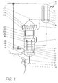
- the make-up water with subcooling of 18 K and more, is essentially heated in three stages. As shown in Fig. 1, the make-up water is fed via a feed line 2 to a 3-way valve 1 and there first divided into a smaller and a larger partial flow. The larger part of the make-up water comprises around 90% of the total flow and the smaller part accordingly around 10%.
- the smaller partial flow is fed to a vertically arranged capacitor stripper 3, which has two separate spatial areas.
- One area comprises two domes 3a, 3b which delimit the capacitor stripper at the top and bottom and which are closed and which are connected to one another via a vertical tube 4.
- the second room area is located between the closed domes 3a and 3b and is delimited by the apparatus inner wall of the capacitor stripper 3.
- the small partial flow is introduced into the upper dome 3a and flows in the vertically arranged bore 4 to the lower dome 3b.
- the tubing 4 is subjected to flushing steam in the opposite flow direction to the internally flowing make-up water.
- the flushing steam is enriched with inert gases from the make-up water. It flows through a steam inlet duct 7 above the lower dome 3b into the condenser stripper 3 and is driven by a suction unit 27 which is connected below the upper dome 3a to a suction nozzle 6 arranged there.
- the purge steam is almost completely condensed and separated from the inert gases. This process is reinforced by harassment 5 in the upper region of the capacitor stripper 3, that is to say in the vicinity of the upper dome 3a.
- the fully condensed purging vapor collects as condensate 8 above the dome 3b and the inert gases with a small residual vapor content are removed from the system by the suction unit 27.
- the rinsing steam advantageously remains in the water-steam circuit, the make-up water in the tube 4 is heated, and the suction unit 4 remains virtually unaffected by the steam volume flow.
- the preheated smaller substream of the make-up water is now fed back to the larger substream at a mixing point 28.
- the entire make-up water then flows through an inlet connector 10 into a likewise vertically arranged apparatus which has three areas over its vertical longitudinal extent.
- the lower part is designed as a steam inflow chamber 14 which closes at the bottom with a dome.
- the cathedral acts here as a collecting vessel 16 for heated and degassed make-up water.
- This tube 13 connects the lower steam inflow chamber 14 to a packing column 23 which is arranged above the tubular film heat exchanger 11 and is surrounded by a jacket film heat exchanger 22.
- the total flow of make-up water preheated by the partial flow thus flows through the inlet connector 10 on the casing side of the pipe 13 into the tubular film heat exchanger 11.
- the make-up water flows from the one at the bottom
- the last heating stage for make-up water takes place in the already mentioned jacket film heat exchanger 22, which is connected above the tubular film heat exchanger 11.
- the make-up water flows out of the outlet port 21 through a line first into a lower collecting ring channel 22a belonging to the jacket film heat exchanger 22.
- the make-up water is driven through a gap of 4 to 7 mm to an upper collecting ring channel 22b, with heat being transferred from the jacketed packing column 23 to the jacket film heat exchanger 22.
- This step completes the heating of the make-up water.
- the make-up water is now approximately saturated, i.e.
- the temperature delta between the exhaust steam from the condenser and the heated make-up water is only about 0.5 K taking into account the steam-side pressure losses.
- the degassing of the heated make-up water begins with the fact that - the make-up water by means of a spray device 24 which with is connected to the upper collecting ring channel 22b, is sprayed in above the packing column 23 and is thereby degassed by means of spontaneous expansion.
- condensate 8 is sprayed in from the condenser stripper 3 via the spray device via a condensate drain 9.
- the make-up water trickling from above and the exhaust steam flowing from below meet in the packing column 23. In this way, the material kinetic degassing is initiated and maintained.
- the state of saturation of the make-up water enables the dissolved inert gases to be easily expelled, as already discussed at the beginning.
- the packing column Since the packing column is used exclusively according to its function as a degasser, its diameter and packing volume are to be dimensioned comparatively significantly smaller than in apparatuses in which the packing column is to both heat and degas. In terms of volume, the packing column used here is approximately 75% smaller than a packing column for a forced double function. Such a smaller packing column is of course correspondingly cheaper, the risk of flooding, as can occur when packing columns with supercooled make-up water, is completely eliminated.
- the additional water trickling out of the packing column and here partially degassed is then heated again by means of a film dispensing device 20 via a tube falling film in the tube 13 by means of steam, since it has emitted thermal energy in the packing column 23.
- the make-up water heated in the tube falling film is first collected in the dome of the steam inflow chamber 14. From there, the make-up water is fed to a trough 17 on a condenser wall, which then supplies the make-up water to the condenser condensate along a falling film by means of a film dispenser 18.
- This measure results in the final degassing of the make-up water, which now has a characteristic O 2 concentration of about 5 ppb, taking into account that all other dissolved gases, such as N 2 , CO 2 , etc., have also been driven off.
- the exhaust steam coming from the condenser and used for heating and degassing carries all the expelled gases with it through a steam line into the condenser stripper.
- the expelled gases and the purge steam are separated here by condensation, which is used at the same time for heating supercooled make-up water.
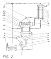
- FIG. 2 A second embodiment according to the invention is shown in FIG. 2.
- the essential difference compared to the first embodiment is the method for heating.
- the heating of the make-up water is carried out here essentially in an additional tube bundle 29 of the condenser 19, with which the tube film heat exchanger 11 is replaced.
- This tube bundle 29 can be implemented here as an integrated component of the condenser tubing.
- the cooling water used in a condenser 19 generally has a straightness of 2 to 3 K with respect to the evaporation temperature on the outflow side. Since the additional water supplied to the additional tube bundle 29 is 2 to 3 K warmer than cooling water, this additional water has approximately the desired saturation on the outflow side.
- the warming-up according to this second exemplary embodiment can, however, preferably only be used when planning a new system, whereas the first exemplary embodiment according to FIG. 1 can also be used in existing power plant systems.
- a decisive advantage of the designs according to the invention is that, despite the large amount of make-up water through optimized use of the heating and degassing measures and by combining suitable apparatus, only one suction unit 27 is required to provide the required driving potential.
- the invention is not limited to the exemplary embodiment shown and described. According to the invention, a combination of the heating by means of tube bundle 29 and tube falling film heat exchanger 11 is also conceivable, for example, a substitution of the packing column in FIG. 2 by a falling film gasifier would also be a variant according to the invention.
Landscapes
- Chemical & Material Sciences (AREA)
- Chemical Kinetics & Catalysis (AREA)
- Degasification And Air Bubble Elimination (AREA)
Abstract
Description
Die Erfindung betrifft ein Verfahren zum Aufwärmen und mehrstufigen Entgasen von Zusatzwasser mittels Dampf in einer Stromerzeugungsanlage. Sie bezieht sich ebenfalls auf eine Apparateanordnung zur Durchführung des Verfahrens.The invention relates to a method for warming up and multi-stage degassing of make-up water by means of steam in a power generation plant. It also relates to an apparatus arrangement for performing the method.
Der konsumptive Verbrauch von entgastem demineralisiertem Wasser in Kombi- und Industriekraftwerksanlagen ist sehr gross. Das führt notwendigerweise zur Behandlung von beträchtlichen Mengen Zusatzwasser zwecks Reposition der Verluste.
Bekannt sind in diesem Zusammenhang besondere Kondensatorkonfigurationen mit Mischvorwärmern/Entgasern, die in der Lage sind, Zusatzwassermengen bis zu 70% der Abdampfmenge aufzuwärmen und zu entgasen. Normalerweise werden in klassischen Kondensationskraftwerksanlagen nicht mehr als 3 bis 5% Zusatzwasser, bezogen auf die Abdampfmenge, direkt in einen Kondensator eingespritzt. Massive Einspritzung von Wasser beeinträchtigt allerdings den Kondensatordruck, da die Kondensatorbündel mit Fremdwasser, also Wasser, dass nicht von der Kondensation stammt, beaufschlagt wird. Das direkte Einsprühen von Zusatzwasser in den Kondensator würde aufgrund der genannten grossen Mengen zu einer Überflutung der Rohrbündel führen. Ein Vakuumverlust wäre unumgänglich, was eine erhebliche Beeinträchtigung der Kondensatorfunktion darstellt.The consumption of degassed demineralized water in combined and industrial power plants is very high. This necessarily leads to the treatment of considerable quantities of make-up water in order to reduce the losses.
In this context, special condenser configurations with mixed preheaters / degassers are known which are able to heat up and degas additional water quantities up to 70% of the evaporation quantity. In classic condensation power plants, no more than 3 to 5% make-up water, based on the amount of waste steam, is normally injected directly into a condenser. However, massive injection of water affects the condenser pressure because the condenser bundle is supplied with extraneous water, i.e. water that does not come from the condensation. The direct spraying of make-up water into the condenser would lead to flooding of the tube bundle due to the large amounts mentioned. A vacuum loss would be unavoidable, which represents a significant impairment of the capacitor function.
Eine wirtschaftliche Aufwärmung und Entgasung von grossen Zusatzwassermengen wird heute mit energetisch niederwertigstem Dampf durchgeführt, wobei-der Gesamtwirkungsgrad des Kraftwerkprozesses nur minimal beeinträchtigt wird. Um diese Aufgabe nach der herkömmlichen Praxis zu erfüllen, werden über dem Kondensator Packungssäulen installiert, in denen unter Verwendung des Turbinenabdampfes als Spülmittel, die Austreibung der im Zusatzwasser gelösten Gase erfolgt. Dabei wird der erforderliche Kondensatordruck unter Zuhilfenahme eines zusätzlichen Saugeraggregates aufrechterhalten.Economical heating and degassing of large amounts of make-up water is carried out today with the lowest-energy steam, whereby the overall efficiency of the power plant process is only minimally impaired. In order to accomplish this task according to conventional practice, packing columns are installed above the condenser, in which the gases dissolved in the make-up water are expelled using the turbine exhaust steam as a flushing agent. The required condenser pressure is maintained with the help of an additional suction unit.
Beim Eintritt des zumeist einrieselnden Zusatzwassers in eine im Gegenstrom betriebene Packungssäule, weist dieses Zusatzwasser in der Regel gegenüber dem Spüldampf eine Unterkühlung von 10°C bis 18°C auf. Für eine ideale Entgasung in einer Packungssäule ist aber annähernd ein thermisches Gleichgewicht zwischen der flüssigen Phase und der Gasphase eine notwendige Bedingung. Wegen der aufgezeigten Unterkühlung muss also zunächst der Abdampf die thermische Sättigung des Zusatzwassers vollziehen. Wenn das Aufwärmen ebenfalls wie das Entgasen in einer Packungssäule erfolgen soll, muss wegen der möglichen Überflutungsgefahr der Säulenquerschnitt einer solchen Packung überdimensional ausgelegt werden. Die Auslegung einer Packungssäule für die genannte Belastung ist aber mit grossen Kosten verbunden.
Der bei der Aufwärmung des herabfliessenden Wassers unwirksam durch eine derartige Packungssäule getriebene Dampf, geht unweigerlich dem Wasser-Dampfkreislauf verloren, da eine effiziente Entgasung, wie erwähnt, erst nach einer Temperaturannäherung des Zusatzwassers an den Spüldampf kleiner 1 K erfolgt. Desweiteren ist die Installation eines weiteren Saugeraggregates in einem Wasser-Dampfkreislauf notwendig, wenn die Packungssäule auch für das Erwärmen des Zusatzwassers eingesetzt wird.When the mostly trickling additional water enters a counter-current packing column, this additional water usually has a subcooling of 10 ° C to 18 ° C compared to the rinsing steam. For an ideal degassing in a packing column, a thermal equilibrium between the liquid phase and the gas phase is a necessary condition. Because of the supercooling shown, the exhaust steam must first carry out the thermal saturation of the make-up water. If heating is also to take place in a packing column like degassing, the column cross-section of such a packing must be oversized due to the possible risk of flooding. The design of a packing column for the load mentioned is associated with great costs.
The steam driven ineffectively by such a packing column during the heating of the flowing down water is inevitably lost to the water-steam cycle, since efficient degassing, as mentioned, only takes place after the temperature of the make-up water approaches the flushing steam less than 1 K. Furthermore, the installation of a further suction unit in a water-steam cycle is necessary if the packing column is also used for heating the make-up water.
Eine wirksame Entgasung wird charakterisiert durch eine Entgasungsspanne an O2 von 10000 ppb (Teile pro Milliarde), dies ist der Sättigungszustand des Wassers mit atmosphärischer Luft und bei Raumtemperatur, herunter auf einstellige ppb - Werte, wie etwa 5 ppb.An effective deaeration is characterized by a Entgasungsspanne of O 2 from 10,000 ppb (parts per billion), this is the state of saturation of water with atmospheric Air and at room temperature down to single digit ppb values, such as 5 ppb.
Es ist daher die Aufgabe der Erfindung, ein Verfahren und eine zur Durchführung des Verfahrens zugehörige Apparateanordnung der eingangs genannten Art dahingehend weiterzuentwickeln, dass energetisch die Aufwärmung und Entgasung des Zusatzwassers mittels Abdampf verbessert und damit preiswerter wird. Gleichzeitig wird die Reduktion des Spüldampfverlustes durch Absaugung während der Aufwärmung und Entgasung angestrebt.It is therefore the object of the invention to further develop a method and an apparatus arrangement of the type mentioned at the outset such that the heating and degassing of the make-up water by means of exhaust steam is improved in terms of energy and thus becomes cheaper. At the same time, the aim is to reduce the loss of flushing steam by suction during heating and degassing.
Erfindungsgemäss wird diese Aufgabe durch die Merkmale der Ansprüche 1 und 4 gelöst.According to the invention, this object is achieved by the features of
Der Kern der Erfindung liegt also darin, das Erwärmen und Entgasen von grossen Mengen Zusatzwasser mittels niederwertigem Dampf getrennt durchzuführen, da ein Entgasen ausschliesslich in thermisch gesättigtem Zustand des Zusatzwasser, also bei annähernd gleicher Temperatur des Zusatzwasser und des Abdampfes, energetisch und wirtschaftlich sinnvoll ist.The essence of the invention is therefore to carry out the heating and degassing of large quantities of make-up water separately using low-quality steam, since degassing is only sensible in terms of energy and economy in the thermally saturated state of the make-up water, i.e. at approximately the same temperature of the make-up water and the exhaust steam.
Eine erste bevorzugte Ausführungsform der Erfindung zeichnet sich dadurch aus, dass zunächst ausschliesslich die thermische Sättigung des Zusatzwassers annähernd vollständig in Hintereinanderschaltung eines Fallfilmwärmeübertragers und eines Mantelspaltwärmeübertragers durchgeführt wird, bevor die Entgasung in einer Packungssäule erfolgt. Das Überfluten einer Packungssäule wird durch das in ihr stattfindende Aufeinandertreffen des Spüldampfes und des gleichtemperierten Zusatzwassers selbst bei vergleichsweise kleinem Säulenquerschnitt ausgeschlossen.
Diese Ausführungsform eignet sich besonders für einen Umbau einer bestehenden Kraftwerksanlage auf einen neuen Standard.A first preferred embodiment of the invention is characterized in that first of all the thermal saturation of the make-up water is carried out almost completely in series with a falling film heat exchanger and a jacket gap heat exchanger before the degassing takes place in a packing column. The flooding of a packing column is prevented by the clashing of the flushing steam and the equal-temperature make-up water, even with a comparatively small column cross-section.
This embodiment is particularly suitable for converting an existing power plant to a new standard.
Bei einer zweiten Ausführungsform der Erfindung erfolgt die wesentliche Erwärmung des Zusatzwassers in einem zusätzlichen Rohrbündel eines Kondensators, und anschliessend wird die Entgasung ausschliesslich in einer Packungssäule oder einem Fallfilmentgaser durchgeführt. Diese Ausführungsvariante eignet sich besonders für den Einsatz in einer Neuanlage.In a second embodiment of the invention the essential heating of the make-up water takes place in an additional tube bundle of a condenser, and the degassing is then carried out exclusively in a packing column or a falling film gasifier. This variant is particularly suitable for use in a new system.
Das neue Verfahren und die neue Apparateanordnung zeichnen sich dadurch aus, dass im Vergleich zu herkömmlichen Methoden und Schaltungen der Gesamtwirkungsgrad der Kraftwerksanlage gesteigert wird, da niederwertiger Abdampf zum Aufwärmen und Entgasen verwendet wird, der dabei vollständig kondensiert wird und dem Kreislauf erhalten bleibt, wobei gleichzeitig der Kondensator entlastet wird.The new method and the new apparatus arrangement are characterized in that the overall efficiency of the power plant system is increased in comparison to conventional methods and circuits, since low-quality exhaust steam is used for heating and degassing, which is fully condensed and retained in the circuit, while at the same time the capacitor is relieved.
In der Zeichnung sind zwei Ausführungsbeispiele der Erfindung anhand einer Vorwärmer-/Entgaserstrasse für Zusatzwasser in einer Kraftwerksanlage schematisch dargestellt.In the drawing, two exemplary embodiments of the invention are shown schematically using a preheater / degasser line for make-up water in a power plant.
Es zeigen:
- Fig. 1
- einen Teillängsschnitt durch einen Kondensator mit einem nachgeschaltetem Fallfilmwärmeübertrager, einem Mantelspaltwärmeübertrager mit einer Packungssäule und einer Kondensator-Stripper-Einheit;
- Fig. 2
- eine Ausführungsvariante der Erfindung.
- Fig. 1
- a partial longitudinal section through a condenser with a downstream falling film heat exchanger, a jacket gap heat exchanger with a packing column and a condenser-stripper unit;
- Fig. 2
- an embodiment of the invention.
Es sind nur die für das Verständnis der Erfindung wesentlichen Elemente gezeigt. Strömungsrichtungen der Arbeitsmittel sind mit Pfeilen dargestellt.Only the elements essential for understanding the invention are shown. Flow directions of the work equipment are shown with arrows.
In Kraftwerksanlagen mit Wärmeauskopplung oder Dampfverbrauchern, wie beispielsweise Brennersysteme mit Dampfeinspritzung zur Schadstoffreduktion oder Leistungserhöhung, können bis zu 100% bezogen auf die Abdampfmenge an Wasser im Wasser-Dampfkreislauf verbraucht werden. Dementsprechend muss kontinuierlich dem Wasser-Dampfkreislauf Zusatzwasser hinzugefügt werden, dass allerdings zuvor den Stoffeigenschaften des Kondensats in einem Kondensator angepasst werden muss. Die beiden hier erörterten Kriterien sind zum einen der Anteil der im Zusatzwasser gelösten Inertgase und zum anderen die Temperatur. Charakteristisch für die im Zusatzwasser gelöste Inertgasmenge ist die Anfangskonzentration an O2 von 10000 ppb (Teile pro Milliarde) unter Raumbedingungen. Dieser Konzentrationswert muss vor dem Eintritt des Zusatzwassers in den Wasser-Dampfkreislauf einer Kraftwerksanlage bis auf einen einstelligen ppb-Wert gesenkt werden.In power plants with heat extraction or steam consumers, such as burner systems with steam injection to reduce pollutants or increase performance, up to 100% based on the amount of water evaporation in the water-steam cycle can be consumed. Accordingly, make-up water must be added continuously to the water-steam cycle, but first the material properties of the condensate in a condenser must be adjusted. The two criteria discussed here are the proportion of the inert gases dissolved in the make-up water and the temperature. The initial concentration of O 2 of 10,000 ppb (parts per billion) under room conditions is characteristic of the amount of inert gas dissolved in the make-up water. Before the make-up water enters the water-steam cycle of a power plant, this concentration value must be reduced to a single-digit ppb value.
Die Entgasung erfolgt zweistufig, und beginnt mit der Entspannungsentgasung unmittelbar nach dem Einsprühen des Zusatzwassers in einen Vakuumraum. Das hier auftretende, explosionsartige Austreiben von Inertgasanteilen lässt sich beschreibend mit "Champagner-Effekt" charakterisieren. Wärmetechnisch optimal wird anschliessend in einer zweiten Phase die Entgasung von Zusatzwasser in gesättigtem Zustand rein stoffkinetisch durchgeführt. Das bedeutet, Spüldampf und Zusatzwasser mit gleicher Temperatur werden in einem Gas-Flüssigkeitskontaktapparat derart zueinandergeführt, dass durch diffusen Transport über die Gas-/Flüssigkeitsgrenzschicht die gelösten Gase ausgetrieben werden. Hieraus lässt sich ableiten, dass die beiden Prozesse Erwärmung und Entgasung des Zusatzwassers dann energetisch und damit auch wirtschaftlich optimiert ablaufen, wenn sie getrennt voneinander durchgeführt werden. Der Verfahrensablauf der Zusatzwasserbehandlung beginnt also mit dem Erwärmen, bis annähernd die Sättigungsbedingungen angenommen worden sind, und endet mit dem Entgasen auf rein stoffkinetischer Basis vor dem Vermischen des behandelten Wassers mit dem Kondensatorkondensat.The degassing takes place in two stages, and begins with the degassing immediately after the additional water has been sprayed into a vacuum chamber. The explosion-like expulsion of inert gas components occurring here can be described descriptively with the "champagne effect". In terms of thermal technology, the degassing of make-up water in saturated state is then carried out purely kinetically in a second phase. This means that rinsing steam and make-up water at the same temperature are brought together in a gas-liquid contact apparatus in such a way that the dissolved gases are expelled through diffuse transport across the gas / liquid boundary layer. From this it can be deduced that the two processes of heating and degassing the make-up water are energy-efficient and therefore also economically optimized if they are carried out separately. The process of the make-up water treatment therefore begins with the heating until the saturation conditions have been approximately reached and ends with the degassing to a purely kinetic level Base before mixing the treated water with the condenser.
Da die beiden Prozesse Erwärmen und Entgasen von grossen Mengen Zusatzwasser weitgehend isoliert und nacheinander ablaufen, wird die Beschreibung anhand der Zeichnung ähnlich strukturiert.Since the two processes of heating and degassing large quantities of make-up water are largely isolated and take place in succession, the description is structured similarly using the drawing.
Das Erwärmen des Zusatzwassers, mit einer Unterkühlung von 18 K und mehr, erfolgt im wesentlichen in drei Stufen. Wie in Fig. 1 dargestellt, wird das Zusatzwasser über eine Zuleitung 2 zu einem 3-Wege-Ventil 1 geführt und dort zunächst in einen kleineren und einen grösseren Teilstrom aufgeteilt. Der grössere Teilstrom des Zusatzwassers umfasst etwa 90% der Gesamtströmung und der kleinere Anteil dementsprechend etwa 10%.The make-up water, with subcooling of 18 K and more, is essentially heated in three stages. As shown in Fig. 1, the make-up water is fed via a
Der kleinere Teilstrom wird einem senkrecht angeordneten Kondensator-Stripper 3 zugeführt, der zwei voneinander getrennte Raumbereiche aufweist. Der eine Raumbereich umfasst zwei, den Kondensator-Stripper oben und unten begrenzende und in sich verschlossene Dome 3a, 3b, die über eine senkrechte Berohrung 4 miteinander verbunden sind. Der zweite Raumbereich befindet sich zwischen den abgeschlossenen Domen 3a und 3b und wird begrenzt von der Apparateinnenwand des Kondensator-Strippers 3. Der kleiner Teilstrom wird in den oberen Dom 3a eingeführt und fliesst in der senkrecht angeordneten Berohrung 4 zum unteren Dom 3b. Mantelseitig wird die Berohrung 4 mit Spüldampf in entgegengesetzter Strömungsrichtung zum inwändig fliessenden Zusatzwasser beaufschlagt. Der Spüldampf ist hier mit Inertgasen des Zusatzwassers angereichert. Er strömt durch einen Dampfeinlasstuzten 7 oberhalb des unteren Doms 3b in den Kondensator-Stripper 3 und wird durch ein Saugeraggregat 27 getrieben, welches unterhalb des oberen Doms 3a an einen dort angeordneten Absaugstutzen 6 angeschlossen ist.The smaller partial flow is fed to a vertically arranged
Durch die Unterkühlung des Zusatzwassers in der Berohrung 4 wird der Spüldampf nahezu vollständig kondensiert und von den Inertgasen separiert. Dieser Vorgang wird verstärkt durch eine Schikanierung 5 im oberen Bereich des Kondensator-Strippers 3, das heisst, in der Nähe des oberen Doms 3a. Nach dieser Phasentrennung sammelt sich der vollständig kondensierte Spüldampf als Kondensat 8 oberhalb des Doms 3b und die Inertgase mit einem geringen Restdampfanteil werden durch das Saugeraggregat 27 aus dem System entfernt. Durch diese nahezu vollständige Kondensation bleibt vorteilhafterweise der Spüldampf dem Wasser-Dampfkreislauf erhalten, das Zusatzwasser in der Berohrung 4 wird erwärmt, und das Saugeraggregat 4 bleibt praktisch unbeaufschlagt von dem Dampfvolumenstrom.By subcooling the make-up water in the
Der vorgewärmte kleinere Teilstrom des Zusatzwassers wird nun dem grösseren Teilstrom an einem Mischpunkt 28 wieder zugeführt. Das gesamte Zusatzwasser strömt anschliessend durch einen Einlasstutzen 10 in einen ebenfalls senkrecht angeordneten Apparat, der über seine senkrechte Längsausdehnung drei Bereiche aufweist. Der untere Teil ist als eine Dampfeinströmkammer 14 ausgebildet, die nach unten mit einem Dom abschliesst. Der Dom fungiert hier als ein Sammelgefäss 16 für erwärmtes und entgastes Zusatzwasser. Oberhalb der Dampfeinströmkammer 14 schliesst sich ein Rohrfallfilmwärmeübertrager 11 an, der durch zwei Abschlussböden 11a, 11b und die Apparatewand begrenzt wird, und eine senkrecht angeordnete Berohrung 13 zwischen den Abschlussböden 11a, 11b aufweist. Diese Berohrung 13 verbindet die untere Dampfeinströmkammer 14 mit einer oberhalb des Rohrfallfilmwärmeübertragers 11 angeordnete Packungssäule 23, die von einem Mantelfilmwärmeübertrager 22 umgeben ist.The preheated smaller substream of the make-up water is now fed back to the larger substream at a
Wie bereits erwähnt, strömt also der vom Teilstrom vorgewärmte Gesamtstrom des Zusatzwassers durch den Einlasstutzen 10 mantelseitig der Berohrung 13 in den Rohrfallfilmwärmeübertrager 11. Das Zusatzwasser strömt von dem am unterenAs already mentioned, the total flow of make-up water preheated by the partial flow thus flows through the
Ende des Rohrfallfilmübertragers 11 angeordneten Einlasstutzen 10 zu dem Auslasstutzen 21 am oberen Ende. Der senkrecht nach oben verlaufenden Strömungssweg des Zusatzwassers wird durch horizontal im Rohrfallfilmwärmeübertrager 11 angeordnete Schikanen 12 verlängert. Damit verlängert sich ebenfalls die Verweilzeit zum Erwärmen des Zusatzwassers in dem Rohrfallfilmwärmeübertrager 11. Die Erwärmung erfolgt mittels niederwertigem Abdampf, der über eine horizontale Dampfleitung 15 aus einem Kondensator 19 der Dampfeinströmkammer 14 zugeführt wird. Der Dampf wird durch die Berohrung 13 nach oben geführt und erwärmt dabei einen herabfallenden Wasserfilm des Rohrfallfilmwärmeübertragers 11. Dieser Wasserfilm überträgt dann seinen Wärmeinhalt teilweise über die Rohrwände der Berohrung 13 weiter an das mantelseitig fliessende Zusatzwasser.End of the tubular falling
Die letzte Erwärmungsstufe für Zusatzwassers findet in dem bereits erwähnten Mantelfilmwärmeübertrager 22 statt, der oberhalb des Rohrfallfilmwärmeübertragers 11 angeschlossen ist. Hierfür strömt das Zusatzwasser aus dem Auslasstutzen 21 durch eine Leitung zunächst in einen zum Mantelfilmwärmeübertrager 22 gehörigen unteren Sammelringkanal 22a. Von dort aus wird das Zusatzwasser durch einen Spalt von 4 bis 7 mm bis zu einem oberen Sammelringkanal 22b getrieben, wobei eine Wärmeübertragung von der ummantelten Packungssäule 23 zum Mantelfilmwärmeübertrager 22 erfolgt. Mit dieser Stufe wird die Erwärmung des Zusatzwasser abgeschlossen. Ausgangsseitig weist das Zusatzwasser nun annähernd Sättigungszustand auf, d.h. das Temperaturdelta zwischen dem Abdampf aus dem Kondensator und dem erwärmten Zusatzwasser beträgt unter Berücksichtigung der dampfseitigen Druckverluste nur noch etwa 0,5 K.The last heating stage for make-up water takes place in the already mentioned jacket
Das Entgasen des erwärmten Zusatzwasser beginnt damit, dass - das Zusatzwasser mittels einer Sprühvorrichtung 24, die mit dem oberen Sammelringkanal 22b verbunden ist, oberhalb der Packungssäule 23 eingesprüht wird und dabei mittels spontaner Entspannung entgast wird. Zugleich wird über einen Kondensatablauf 9 Kondensat 8 aus dem Kondenstor-Stripper 3 über die Sprühvorrichtung eingesprüht. Im Gegenstromprinzip begegnen sich in der Packungssäule 23 das von oben rieselnde Zusatzwasser und der von unten strömende Abdampf. Hierdurch wird die stoffkinetische Entgasung eingeleitet und aufrechterhalten. Der Sättigungszustand des Zusatzwassers ermöglicht das leichte Austreiben der gelösten Inertgase, wie eingangs bereits erörtert wurde. Da die Packungssäule hier ausschliesslich gemäss ihrer Funktion als Entgaser verwendet wird, ist ihr Durchmesser und ihr Packungsvolumen vergleichsweise deutlich kleiner zu dimensionieren, als in Apparaten, in denen die Packungssäule sowohl erwärmen wie auch entgasen soll. Bezüglich des Volumens ist die hier verwendete Packungssäule etwa 75% kleiner als eine Packungssäule für eine erzwungene Doppelfunktion. Eine derart kleinere Packungssäule ist natürlich entsprechend preiswerter, wobei die Gefahr einer Überflutung, wie sie bei Beaufschlagung von Packungssäulen mit unterkühltem Zusatzwasser auftreten kann, völlig ausgeschlossen wird.The degassing of the heated make-up water begins with the fact that - the make-up water by means of a
Das aus der Packungssäule rieselnde und hier teilentgaste Zusatzwasser wird nun mittels einer Filmabgabevorrichtung 20 über einen Rohrfallfilm in der Berohrung 13 wieder mittels Dampf erwärmt, da es in der Packungssäule 23 Wärmeenergie abgegeben hat. Für eine weitere Entgasung wird zunächst das im Rohrfallfilm erwärmte Zusatzwasser im Dom der Dampfeinströmkammer 14 gesammelt. Von dort aus wird das Zusatzwasser einer Wanne 17 an einer Kondensatorwand zugeführt, die das Zusatzwasser anschliessend mittels einer Filmabgabevorrichtung 18 entlang eines Wandfallfilms dem Kondensatorkondensat zugeführt. Durch diese Massnahme erfolgt die abschliessende Entgasung des Zusatzwassers, das nun eine charakteristische O2-Konzentration von etwa 5 ppb aufweist, wobei zu berücksichtigen ist, dass sämtliche weiteren gelösten Gase, wie N2, CO2, etc., ebenfalls ausgetrieben wurden.The additional water trickling out of the packing column and here partially degassed is then heated again by means of a film dispensing device 20 via a tube falling film in the
Der aus dem Kondensator stammende und zum Erwärmen und Entgasen verwendete Abdampf führt oberhalb der Sprühvorrichtung 24 alle ausgetriebenen Gase mit sich durch eine Dampfleitung in den Kondensator-Stripper. Wie bereits erläutert, erfolgt hier eine Separierung der ausgetriebenen Gase und des Spüldampfes durch eine Kondensation, die gleichzeitig zum Erwärmen von unterkühltem Zusatzwasser genutzt wird.The exhaust steam coming from the condenser and used for heating and degassing carries all the expelled gases with it through a steam line into the condenser stripper. As already explained, the expelled gases and the purge steam are separated here by condensation, which is used at the same time for heating supercooled make-up water.
Eine zweite erfindungsgemässe Ausführung zeigt Fig. 2. Wesentlicher Unterschied im Vergleich zur ersten Ausführungsform, ist das Verfahren zum Erwärmen. Das Erwärmen des Zusatzwassers wird hier massgeblich in einem zusätzlichen Rohrbündel 29 des Kondensators 19 durchgeführt, womit der Rohrfallfilmwärmeübertrager 11 ersetzt wird. Dieses Rohrbündel 29 lässt sich hier als integrierten Bestandteil der Kondensatorberohrung ausführen. Das in einem Kondensator 19 verwendete Kühlwasser weist abströmseitig in der Regel eine Grädigkeit von 2 bis 3 K bezüglich der Abdampftemperatur auf. Da das dem zusätzlichen Rohrbündel 29 zugeführt Zusatzwasser 2 bis 3 K wärmer als Kühlwasser ist, weist dieses Zusatzwasser abströmseitig annähernd die gewünschte Sättigung auf.A second embodiment according to the invention is shown in FIG. 2. The essential difference compared to the first embodiment is the method for heating. The heating of the make-up water is carried out here essentially in an
Die Aufwärmung gemäss diesem zweiten Ausführungsbeispiels ist allerdings vorzugsweise nur bei der Projektierung einer Neuanlage anwendbar, wohingegen das erste Ausführungsbeispiel nach Fig. 1 auch in bestehenden Kraftwerksanlagen zur Anwendung kommen kann.The warming-up according to this second exemplary embodiment can, however, preferably only be used when planning a new system, whereas the first exemplary embodiment according to FIG. 1 can also be used in existing power plant systems.
Ein entscheidender Vorteil der erfindungsgemässen Ausführungen ist, dass trotz der grossen Zusatzwassermenge durch optimierte Nutzung der Erwärmungs- und Entgasungsmassnahmen und unter Kombination geeigneter Apparate nur ein Saugeraggregat 27 für die Bereitstellung des geforderten treibenden Potentials benötigt wird.A decisive advantage of the designs according to the invention is that, despite the large amount of make-up water through optimized use of the heating and degassing measures and by combining suitable apparatus, only one
Selbstverständlich ist die Erfindung nicht auf das gezeigte und beschriebene Ausführungsbeispiel beschränkt. Erfindungsgemäss denkbar ist beispielsweise ebenfalls eine Kombination der Erwärmung mittels Rohrbündel 29 und Rohrfallfilmwärmeübertrager 11. Auch eine Substitution der Packungssäule in Fig. 2 durch einen Fallfilmentgaser wäre eine erfindungsgemässe Variante.Of course, the invention is not limited to the exemplary embodiment shown and described. According to the invention, a combination of the heating by means of
- 11
- 3-Wege-Ventil3-way valve
- 22nd
- ZuleitungSupply
- 33rd
- Kondensator-StripperCapacitor stripper
- 3a,b3a, b
- DomCathedral
- 44th
- BerohrungTubing
- 55
- Schikanechicane
- 66
- AbsaugstutzenExtraction nozzle
- 77
- DampfeinlasstutzenSteam inlet connector
- 88th
- Kondensatcondensate
- 99
- KondensatablaufCondensate drain
- 1010th
- EinlasstutzenInlet spigot
- 1111
- RohrfallfilmwärmeübertragerPipe falling film heat exchanger
- 11a11a
- AbschlussbodenFinal floor
- 11b11b
- AbschlussbodenFinal floor
- 1212th
- Schikanechicane
- 1313
- BerohrungTubing
- 1414
- DampfeinströmkammerSteam inflow chamber
- 1515
- DampfzuleitungSteam supply
- 1616
- SammelgefässCollecting vessel
- 1717th
- WanneTub
- 1818th
- FilmabgabevorrichtungFilm dispenser
- 1919th
- Kondensatorcapacitor
- 2020th
- FilmabgabevorrichtungFilm dispenser
- 2121
- AuslasstutzenExhaust port
- 2222
- MantelfilmwärmeübertragerJacket film heat exchanger
- 22a22a
- SammelringkanalManifold channel
- 22b22b
- SammelringkanalManifold channel
- 2323
- PackungssäulePacking column
- 2424th
- SprühvorrichtungSpraying device
- 2525th
- Rohrpipe
- 2626
- DampfleitungSteam pipe
- 2727
- SaugeraggregatVacuum unit
- 2828
- MischpunktMixing point
- 2929
- RohrbündelTube bundle
- 3030th
- WandfallfilmWall falling film
Claims (7)
dadurch gekennzeichnet,
characterized,
dadurch gekennzeichnet,
characterized,
dadurch gekennzeichnet,
dass zum Aufwärmen und Entgasen Dampf verwendete wird, der zuvor in einer Niederdruckturbine vollständig entspannt wurde.Method according to claim 1,
characterized,
that steam is used for warming up and degassing, which was previously completely expanded in a low pressure turbine.
dadurch gekennzeichnet,
characterized,
dadurch gekennzeichnet,
characterized,
dadurch gekennzeichnet,
characterized,
dadurch gekennzeichnet,
dass die Apparate zum Erwärmen des Zusatzwassers einen Kondensator-Stripper (3) und einen Kondensator (19) umfassen, in welchem das Zusatzwasser durch ein separat angeordnetes Rohrbündel (29) geführt wird.Apparatus arrangement according to claim 4,
characterized,
that the apparatus for heating the make-up water comprise a condenser stripper (3) and a condenser (19) in which the make-up water is passed through a separately arranged tube bundle (29).
Applications Claiming Priority (2)
| Application Number | Priority Date | Filing Date | Title |
|---|---|---|---|
| DE19549139A DE19549139A1 (en) | 1995-12-29 | 1995-12-29 | Process and apparatus arrangement for heating and multi-stage degassing of water |
| DE19549139 | 1995-12-29 |
Publications (3)
| Publication Number | Publication Date |
|---|---|
| EP0781583A2 true EP0781583A2 (en) | 1997-07-02 |
| EP0781583A3 EP0781583A3 (en) | 1998-01-21 |
| EP0781583B1 EP0781583B1 (en) | 2003-07-23 |
Family
ID=7781641
Family Applications (1)
| Application Number | Title | Priority Date | Filing Date |
|---|---|---|---|
| EP96810832A Expired - Lifetime EP0781583B1 (en) | 1995-12-29 | 1996-11-28 | Process and apparatus for heating and multiple degassing of water |
Country Status (5)
| Country | Link |
|---|---|
| US (2) | US5930998A (en) |
| EP (1) | EP0781583B1 (en) |
| AU (1) | AU696041B2 (en) |
| DE (2) | DE19549139A1 (en) |
| ES (1) | ES2205010T3 (en) |
Cited By (4)
| Publication number | Priority date | Publication date | Assignee | Title |
|---|---|---|---|---|
| EP0933109A3 (en) * | 1998-01-28 | 1999-12-15 | OTTO HEAT Heizungs-, Energie- und Anlagentechnik GmbH & Co., KG | Apparatus for de-gasing liquid media |
| DE19924853A1 (en) * | 1999-05-31 | 2000-12-07 | Asea Brown Boveri | Water for combined heat and power station is warmed and de-gassed in compact assembly at low cost |
| EP1095686A1 (en) * | 1999-10-29 | 2001-05-02 | Voith Paper Patent GmbH | Process and equipment to ventilate a paper stock suspension |
| CN119164216A (en) * | 2024-11-22 | 2024-12-20 | 安徽盛特环境科技有限公司 | A low-temperature waste heat recovery system for acid production from non-ferrous smelting flue gas |
Families Citing this family (13)
| Publication number | Priority date | Publication date | Assignee | Title |
|---|---|---|---|---|
| US6372699B1 (en) * | 1997-12-22 | 2002-04-16 | Kurita Water Industries Ltd. | Cleaning solution for electronic materials and method for using same |
| FI106296B (en) | 1998-11-09 | 2001-01-15 | Amsco Europ Inc Suomen Sivulii | Method and apparatus for treating water for evaporation |
| RU2182116C1 (en) * | 2001-06-05 | 2002-05-10 | Ульяновский государственный технический университет | Water thermal deaeration process |
| RU2183196C1 (en) * | 2001-06-05 | 2002-06-10 | Ульяновский государственный технический университет | Deaeration apparatus |
| US6619042B2 (en) * | 2001-10-01 | 2003-09-16 | Holtec International, Inc. | Deaeration of makeup water in a steam surface condenser |
| RU2197433C1 (en) * | 2002-01-08 | 2003-01-27 | Ульяновский государственный технический университет | Vacuum-type deaeration unit |
| RU2210542C1 (en) * | 2002-01-08 | 2003-08-20 | Ульяновский государственный технический университет | Method of thermal deaeration of water |
| DE10245935A1 (en) * | 2002-09-30 | 2004-05-19 | Alstom (Switzerland) Ltd. | Venting / degassing system for power plant condensers |
| DE10302870B3 (en) * | 2003-01-28 | 2004-08-05 | Stabilus Gmbh | Setting device with gas spring providing damped setting movement for pivoted flap or adjustable seat in automobile or domestic appliance door |
| DE102005040380B3 (en) * | 2005-08-25 | 2006-07-27 | Gea Energietechnik Gmbh | Water vapor/exhaust steam condensation method for thermal power plant, involves supplying steam flow from condenser to deaerator in which feed water is heated by partial steam flow, parallel to heating of condensate in warming stage |
| CN103988640A (en) * | 2014-05-22 | 2014-08-20 | 孙明芹 | Supporting fork below straw returning-to-field mechanism |
| DE102014217280A1 (en) * | 2014-08-29 | 2016-03-03 | Siemens Aktiengesellschaft | Method and arrangement of a steam turbine plant in combination with a thermal water treatment |
| CN106195997A (en) * | 2016-08-25 | 2016-12-07 | 中国五环工程有限公司 | Synthetic ammonia installation waste heat reclaiming process method and system thereof |
Family Cites Families (26)
| Publication number | Priority date | Publication date | Assignee | Title |
|---|---|---|---|---|
| DE957948C (en) * | 1957-01-24 | LICENTIA Patent-Verwaltungs-G mbH, Hamburg | Steam power plant with mixing preheater and turbine-driven pumps | |
| DE1110615B (en) * | 1956-05-12 | 1961-07-13 | Friedrich Johswich Dr Ing | Process and device for the thermal degassing of liquids by relaxation |
| US3330980A (en) * | 1965-07-16 | 1967-07-11 | Rca Corp | Shadow mask mounted with bi-metallic sections connected by expansible loop |
| US3803846A (en) * | 1971-06-14 | 1974-04-16 | S Letvin | Waste heat recovery process |
| AT374903B (en) * | 1975-10-23 | 1984-06-12 | Waagner Biro Ag | DEVICE FOR MIXED DEGASSING OF LIQUIDS |
| US4969507A (en) * | 1977-06-30 | 1990-11-13 | Rosenblad Axel E | Integral blow down concentrator with air-cooled surface condenser |
| US4241585A (en) * | 1978-04-14 | 1980-12-30 | Foster Wheeler Energy Corporation | Method of operating a vapor generating system having integral separators and a constant pressure furnace circuitry |
| US4288989A (en) * | 1979-02-05 | 1981-09-15 | Cassidy James L | Method and apparatus for obtaining mechanical energy from low temperature heat sources |
| SU1000717A1 (en) * | 1981-05-21 | 1983-02-28 | Предприятие П/Я Г-4841 | Film-type heat exchanger |
| CH665451A5 (en) * | 1983-07-19 | 1988-05-13 | Bbc Brown Boveri & Cie | METHOD FOR CLEANING AND DEGASSING THE CONDENSATE / FEED WATER IN A CIRCUIT OF A POWER GENERATION SYSTEM. |
| JPS60169084A (en) * | 1984-02-14 | 1985-09-02 | Hitachi Ltd | Condenser deaeration method and equipment |
| SE452745B (en) * | 1984-04-24 | 1987-12-14 | Ahlstroem Foeretagen | VERTICAL ROD TYPE CRAFT MOVERS |
| US4552099A (en) * | 1984-10-25 | 1985-11-12 | Westinghouse Electric Corp. | Anticipatory boiler feedpump suction head controller system |
| DE3662612D1 (en) * | 1985-09-20 | 1989-05-03 | Bbc Brown Boveri & Cie | Device for degassing the condensate in the circuit of an electricity power unit |
| US4683025A (en) * | 1986-02-10 | 1987-07-28 | The Graver Company | Method and apparatus to convert a long tube vertical evaporator to a falling film evaporator |
| DE3719861C2 (en) * | 1986-08-20 | 1988-08-04 | Koerting Ag | STEAM TURBINE SYSTEM |
| DE3709652A1 (en) * | 1987-03-24 | 1988-10-06 | Thermo Consulting Heidelberg | DEVICE FOR EVAPORATING LIQUIDS OR ABSORBING OR DEGASSING TWO- OR MULTIPLE-MATERIAL SOLUTIONS IN DOWNTUBE CASE FILM DESIGN |
| US4819436A (en) * | 1988-05-26 | 1989-04-11 | General Electric Company | Deaerator pressure control system |
| HUT47173A (en) * | 1988-08-19 | 1990-01-30 | Energiagazdalkodasi Intezet | Apparatus for replacing the feedwater of power plant |
| US4873829A (en) * | 1988-08-29 | 1989-10-17 | Williamson Anthony R | Steam power plant |
| CH682982A5 (en) * | 1990-06-11 | 1993-12-31 | Asea Brown Boveri | Apparatus for heating and degassing of water. |
| DE4022544A1 (en) * | 1990-07-16 | 1992-01-23 | Siemens Ag | Method for degassing condensate - works in combined gas and steam turbine plant with heated part flow of condensate additionally degassed by temp. adjustment |
| US5165237A (en) * | 1991-03-08 | 1992-11-24 | Graham Corporation | Method and apparatus for maintaining a required temperature differential in vacuum deaerators |
| US5246541A (en) * | 1991-05-14 | 1993-09-21 | A. Ahlstrom Corporation | Evaporator for liquid solutions |
| EP0561012B1 (en) * | 1992-03-16 | 1996-05-29 | Asea Brown Boveri Ag | Method and apparatus for water treatment in a surface condenser |
| DE19513204A1 (en) * | 1995-04-11 | 1996-10-17 | Abb Management Ag | Apparatus for heating and degassing water |
-
1995
- 1995-12-29 DE DE19549139A patent/DE19549139A1/en not_active Ceased
-
1996
- 1996-11-28 DE DE59610617T patent/DE59610617D1/en not_active Expired - Lifetime
- 1996-11-28 ES ES96810832T patent/ES2205010T3/en not_active Expired - Lifetime
- 1996-11-28 EP EP96810832A patent/EP0781583B1/en not_active Expired - Lifetime
- 1996-12-04 US US08/760,334 patent/US5930998A/en not_active Expired - Lifetime
- 1996-12-24 AU AU76450/96A patent/AU696041B2/en not_active Expired
-
1999
- 1999-06-21 US US09/336,734 patent/US6145315A/en not_active Expired - Lifetime
Non-Patent Citations (1)
| Title |
|---|
| None |
Cited By (5)
| Publication number | Priority date | Publication date | Assignee | Title |
|---|---|---|---|---|
| EP0933109A3 (en) * | 1998-01-28 | 1999-12-15 | OTTO HEAT Heizungs-, Energie- und Anlagentechnik GmbH & Co., KG | Apparatus for de-gasing liquid media |
| DE19924853A1 (en) * | 1999-05-31 | 2000-12-07 | Asea Brown Boveri | Water for combined heat and power station is warmed and de-gassed in compact assembly at low cost |
| EP1095686A1 (en) * | 1999-10-29 | 2001-05-02 | Voith Paper Patent GmbH | Process and equipment to ventilate a paper stock suspension |
| US6425986B1 (en) | 1999-10-29 | 2002-07-30 | Voith Sulzer Papiertechnik Patent Gmbh | Process for degassing a paper stock suspension |
| CN119164216A (en) * | 2024-11-22 | 2024-12-20 | 安徽盛特环境科技有限公司 | A low-temperature waste heat recovery system for acid production from non-ferrous smelting flue gas |
Also Published As
| Publication number | Publication date |
|---|---|
| US6145315A (en) | 2000-11-14 |
| AU696041B2 (en) | 1998-08-27 |
| EP0781583A3 (en) | 1998-01-21 |
| DE59610617D1 (en) | 2003-08-28 |
| DE19549139A1 (en) | 1997-07-03 |
| ES2205010T3 (en) | 2004-05-01 |
| EP0781583B1 (en) | 2003-07-23 |
| AU7645096A (en) | 1997-02-27 |
| US5930998A (en) | 1999-08-03 |
Similar Documents
| Publication | Publication Date | Title |
|---|---|---|
| EP0781583B1 (en) | Process and apparatus for heating and multiple degassing of water | |
| DE10330859A1 (en) | Operating emission-free gas turbine power plant involves feeding some compressed circulated gas directly to combustion chamber, cooling/humidifying some gas before feeding to combustion chamber | |
| DE2219650A1 (en) | Distillation process and apparatus for carrying out the process | |
| EP0461515B1 (en) | Device for treating and degasifying of water | |
| AT394100B (en) | HEAT STEAM GENERATOR | |
| WO1997046304A1 (en) | Process and device for drying gas, especially natural gas | |
| EP0215230B1 (en) | Device for degassing the condensate in the circuit of an electricity power unit | |
| DE19544224B4 (en) | Chemical operation of a water / steam cycle | |
| EP0894948A1 (en) | Combined gas-steam power plant with once-through steam generator | |
| DE69520366T2 (en) | METHOD FOR FINAL EVAPORATION OF BLACK LYE | |
| EP1425079B1 (en) | Method and device for thermal de-gassing of the active substance of a two-phase process | |
| EP0619466B1 (en) | Steam condenser | |
| EP0425941B1 (en) | Apparatus for degasification and heating of water | |
| EP0463448B1 (en) | Method and apparatus for heating and multiple effect degasification of water | |
| EP0867214A2 (en) | Apparatus for heating and degassing water | |
| DE4230266A1 (en) | Method and device for heat recovery in the chemical degradation of sewage sludge or waste water | |
| EP1576331B1 (en) | Power plant condenser with deaeration/degassing system | |
| DE3133803C2 (en) | Process for concentrating aqueous solutions of glycols by multi-effect distillation | |
| DE2717505A1 (en) | TWO-STAGE EVAPORATOR | |
| DE3838932C1 (en) | Process and plant for the physical refining of edible oils, fats and esters | |
| EP0737500A2 (en) | Apparatus for degassification and heating of water | |
| DE19848748A1 (en) | Process for starting a steam system and steam system for carrying out the process | |
| DE3323120C2 (en) | Process and system for deodorising and / or deacidifying cocoa butter and cocoa butter substitutes | |
| DE3236985C2 (en) | ||
| EP1249662B1 (en) | Steam generator |
Legal Events
| Date | Code | Title | Description |
|---|---|---|---|
| PUAI | Public reference made under article 153(3) epc to a published international application that has entered the european phase |
Free format text: ORIGINAL CODE: 0009012 |
|
| AK | Designated contracting states |
Kind code of ref document: A2 Designated state(s): BE DE ES FR IT NL |
|
| PUAL | Search report despatched |
Free format text: ORIGINAL CODE: 0009013 |
|
| AK | Designated contracting states |
Kind code of ref document: A3 Designated state(s): BE DE ES FR IT NL |
|
| 17P | Request for examination filed |
Effective date: 19980702 |
|
| 17Q | First examination report despatched |
Effective date: 20010427 |
|
| RAP1 | Party data changed (applicant data changed or rights of an application transferred) |
Owner name: ALSTOM |
|
| RAP1 | Party data changed (applicant data changed or rights of an application transferred) |
Owner name: ALSTOM (SWITZERLAND) LTD |
|
| GRAH | Despatch of communication of intention to grant a patent |
Free format text: ORIGINAL CODE: EPIDOS IGRA |
|
| GRAH | Despatch of communication of intention to grant a patent |
Free format text: ORIGINAL CODE: EPIDOS IGRA |
|
| GRAA | (expected) grant |
Free format text: ORIGINAL CODE: 0009210 |
|
| AK | Designated contracting states |
Designated state(s): BE DE ES FR IT NL |
|
| PG25 | Lapsed in a contracting state [announced via postgrant information from national office to epo] |
Ref country code: FR Free format text: LAPSE BECAUSE OF FAILURE TO SUBMIT A TRANSLATION OF THE DESCRIPTION OR TO PAY THE FEE WITHIN THE PRESCRIBED TIME-LIMIT Effective date: 20030723 |
|
| REF | Corresponds to: |
Ref document number: 59610617 Country of ref document: DE Date of ref document: 20030828 Kind code of ref document: P |
|
| PG25 | Lapsed in a contracting state [announced via postgrant information from national office to epo] |
Ref country code: BE Free format text: LAPSE BECAUSE OF NON-PAYMENT OF DUE FEES Effective date: 20031130 |
|
| REG | Reference to a national code |
Ref country code: ES Ref legal event code: FG2A Ref document number: 2205010 Country of ref document: ES Kind code of ref document: T3 |
|
| PLBE | No opposition filed within time limit |
Free format text: ORIGINAL CODE: 0009261 |
|
| STAA | Information on the status of an ep patent application or granted ep patent |
Free format text: STATUS: NO OPPOSITION FILED WITHIN TIME LIMIT |
|
| BERE | Be: lapsed |
Owner name: *ALSTOM (SWITZERLAND) LTD Effective date: 20031130 |
|
| 26N | No opposition filed |
Effective date: 20040426 |
|
| EN | Fr: translation not filed | ||
| REG | Reference to a national code |
Ref country code: NL Ref legal event code: SD Effective date: 20120709 |
|
| REG | Reference to a national code |
Ref country code: DE Ref legal event code: R082 Ref document number: 59610617 Country of ref document: DE Representative=s name: UWE ROESLER, DE |
|
| REG | Reference to a national code |
Ref country code: ES Ref legal event code: PC2A Owner name: ALSTOM TECHNOLOGY LTD. Effective date: 20120814 |
|
| REG | Reference to a national code |
Ref country code: DE Ref legal event code: R082 Ref document number: 59610617 Country of ref document: DE Representative=s name: RUEGER, BARTHELT & ABEL, DE Effective date: 20120713 Ref country code: DE Ref legal event code: R082 Ref document number: 59610617 Country of ref document: DE Representative=s name: ROESLER, UWE, DIPL.-PHYS.UNIV., DE Effective date: 20120713 Ref country code: DE Ref legal event code: R081 Ref document number: 59610617 Country of ref document: DE Owner name: GENERAL ELECTRIC TECHNOLOGY GMBH, CH Free format text: FORMER OWNER: ALSTOM (SWITZERLAND) LTD., BADEN, CH Effective date: 20120713 Ref country code: DE Ref legal event code: R081 Ref document number: 59610617 Country of ref document: DE Owner name: ALSTOM TECHNOLOGY LTD., CH Free format text: FORMER OWNER: ALSTOM (SWITZERLAND) LTD., BADEN, CH Effective date: 20120713 |
|
| PGFP | Annual fee paid to national office [announced via postgrant information from national office to epo] |
Ref country code: IT Payment date: 20151125 Year of fee payment: 20 Ref country code: DE Payment date: 20151119 Year of fee payment: 20 |
|
| PGFP | Annual fee paid to national office [announced via postgrant information from national office to epo] |
Ref country code: ES Payment date: 20151111 Year of fee payment: 20 Ref country code: NL Payment date: 20151118 Year of fee payment: 20 |
|
| REG | Reference to a national code |
Ref country code: DE Ref legal event code: R082 Ref document number: 59610617 Country of ref document: DE Representative=s name: RUEGER ABEL PATENTANWAELTE PARTGMBB, DE Ref country code: DE Ref legal event code: R082 Ref document number: 59610617 Country of ref document: DE Representative=s name: RUEGER, BARTHELT & ABEL, DE |
|
| REG | Reference to a national code |
Ref country code: NL Ref legal event code: HC Owner name: GENERAL ELECTRIC TECHNOLOGY GMBH; CH Free format text: DETAILS ASSIGNMENT: VERANDERING VAN EIGENAAR(S), VERANDERING VAN NAAM VAN DE EIGENAAR(S); FORMER OWNER NAME: ALSTOM TECHNOLOGY LTD Effective date: 20160623 |
|
| REG | Reference to a national code |
Ref country code: DE Ref legal event code: R082 Ref document number: 59610617 Country of ref document: DE Representative=s name: RUEGER, BARTHELT & ABEL, DE Ref country code: DE Ref legal event code: R081 Ref document number: 59610617 Country of ref document: DE Owner name: GENERAL ELECTRIC TECHNOLOGY GMBH, CH Free format text: FORMER OWNER: ALSTOM TECHNOLOGY LTD., BADEN, CH |
|
| REG | Reference to a national code |
Ref country code: ES Ref legal event code: PC2A Owner name: GENERAL ELECTRIC TECHNOLOGY GMBH Effective date: 20161013 |
|
| REG | Reference to a national code |
Ref country code: DE Ref legal event code: R071 Ref document number: 59610617 Country of ref document: DE |
|
| REG | Reference to a national code |
Ref country code: NL Ref legal event code: MK Effective date: 20161127 |
|
| REG | Reference to a national code |
Ref country code: ES Ref legal event code: FD2A Effective date: 20170306 |
|
| PG25 | Lapsed in a contracting state [announced via postgrant information from national office to epo] |
Ref country code: ES Free format text: LAPSE BECAUSE OF EXPIRATION OF PROTECTION Effective date: 20161129 |