EP0215230B1 - Device for degassing the condensate in the circuit of an electricity power unit - Google Patents
Device for degassing the condensate in the circuit of an electricity power unit Download PDFInfo
- Publication number
- EP0215230B1 EP0215230B1 EP86109757A EP86109757A EP0215230B1 EP 0215230 B1 EP0215230 B1 EP 0215230B1 EP 86109757 A EP86109757 A EP 86109757A EP 86109757 A EP86109757 A EP 86109757A EP 0215230 B1 EP0215230 B1 EP 0215230B1
- Authority
- EP
- European Patent Office
- Prior art keywords
- steam
- condensate
- condenser
- degassing
- flow channel
- Prior art date
- Legal status (The legal status is an assumption and is not a legal conclusion. Google has not performed a legal analysis and makes no representation as to the accuracy of the status listed.)
- Expired
Links
- 238000007872 degassing Methods 0.000 title claims description 31
- 230000005611 electricity Effects 0.000 title claims 2
- XLYOFNOQVPJJNP-UHFFFAOYSA-N water Substances O XLYOFNOQVPJJNP-UHFFFAOYSA-N 0.000 claims description 46
- 229910052760 oxygen Inorganic materials 0.000 claims description 22
- 239000001301 oxygen Substances 0.000 claims description 22
- QVGXLLKOCUKJST-UHFFFAOYSA-N atomic oxygen Chemical compound [O] QVGXLLKOCUKJST-UHFFFAOYSA-N 0.000 claims description 19
- 230000005494 condensation Effects 0.000 claims description 15
- 238000009833 condensation Methods 0.000 claims description 14
- 238000005507 spraying Methods 0.000 claims description 5
- 238000011010 flushing procedure Methods 0.000 claims description 4
- 238000005260 corrosion Methods 0.000 description 10
- 230000007797 corrosion Effects 0.000 description 10
- 239000003990 capacitor Substances 0.000 description 6
- 238000004140 cleaning Methods 0.000 description 5
- 239000000498 cooling water Substances 0.000 description 5
- 241001136792 Alle Species 0.000 description 4
- 239000000203 mixture Substances 0.000 description 4
- CURLTUGMZLYLDI-UHFFFAOYSA-N Carbon dioxide Chemical compound O=C=O CURLTUGMZLYLDI-UHFFFAOYSA-N 0.000 description 3
- RYGMFSIKBFXOCR-UHFFFAOYSA-N Copper Chemical compound [Cu] RYGMFSIKBFXOCR-UHFFFAOYSA-N 0.000 description 3
- 239000003795 chemical substances by application Substances 0.000 description 3
- 229910052802 copper Inorganic materials 0.000 description 3
- 239000010949 copper Substances 0.000 description 3
- QGZKDVFQNNGYKY-UHFFFAOYSA-N Ammonia Chemical compound N QGZKDVFQNNGYKY-UHFFFAOYSA-N 0.000 description 2
- 229910000881 Cu alloy Inorganic materials 0.000 description 2
- 241001295925 Gegenes Species 0.000 description 2
- 239000000356 contaminant Substances 0.000 description 2
- 238000003795 desorption Methods 0.000 description 2
- 230000002349 favourable effect Effects 0.000 description 2
- 238000002347 injection Methods 0.000 description 2
- 239000007924 injection Substances 0.000 description 2
- 239000002184 metal Substances 0.000 description 2
- 229910052751 metal Inorganic materials 0.000 description 2
- 229920006395 saturated elastomer Polymers 0.000 description 2
- 239000007921 spray Substances 0.000 description 2
- 238000009423 ventilation Methods 0.000 description 2
- 241000252169 Catostomus commersonii Species 0.000 description 1
- 238000010793 Steam injection (oil industry) Methods 0.000 description 1
- 238000009825 accumulation Methods 0.000 description 1
- 229910021529 ammonia Inorganic materials 0.000 description 1
- 230000033228 biological regulation Effects 0.000 description 1
- 230000015572 biosynthetic process Effects 0.000 description 1
- 238000007664 blowing Methods 0.000 description 1
- 229910002092 carbon dioxide Inorganic materials 0.000 description 1
- 239000001569 carbon dioxide Substances 0.000 description 1
- 230000007423 decrease Effects 0.000 description 1
- 238000010586 diagram Methods 0.000 description 1
- 230000000694 effects Effects 0.000 description 1
- 238000001983 electron spin resonance imaging Methods 0.000 description 1
- 230000003628 erosive effect Effects 0.000 description 1
- 239000007789 gas Substances 0.000 description 1
- 230000001771 impaired effect Effects 0.000 description 1
- 239000011261 inert gas Substances 0.000 description 1
- 239000007788 liquid Substances 0.000 description 1
- 238000005259 measurement Methods 0.000 description 1
- 238000000034 method Methods 0.000 description 1
- 150000002926 oxygen Chemical class 0.000 description 1
- 238000010248 power generation Methods 0.000 description 1
- 238000004321 preservation Methods 0.000 description 1
- 239000008213 purified water Substances 0.000 description 1
- 230000000630 rising effect Effects 0.000 description 1
- 238000000926 separation method Methods 0.000 description 1
- 239000000243 solution Substances 0.000 description 1
- 238000011144 upstream manufacturing Methods 0.000 description 1
- 238000013022 venting Methods 0.000 description 1
Images
Classifications
-
- B—PERFORMING OPERATIONS; TRANSPORTING
- B01—PHYSICAL OR CHEMICAL PROCESSES OR APPARATUS IN GENERAL
- B01D—SEPARATION
- B01D19/00—Degasification of liquids
-
- B—PERFORMING OPERATIONS; TRANSPORTING
- B01—PHYSICAL OR CHEMICAL PROCESSES OR APPARATUS IN GENERAL
- B01D—SEPARATION
- B01D19/00—Degasification of liquids
- B01D19/0005—Degasification of liquids with one or more auxiliary substances
- B01D19/001—Degasification of liquids with one or more auxiliary substances by bubbling steam through the liquid
-
- F—MECHANICAL ENGINEERING; LIGHTING; HEATING; WEAPONS; BLASTING
- F01—MACHINES OR ENGINES IN GENERAL; ENGINE PLANTS IN GENERAL; STEAM ENGINES
- F01K—STEAM ENGINE PLANTS; STEAM ACCUMULATORS; ENGINE PLANTS NOT OTHERWISE PROVIDED FOR; ENGINES USING SPECIAL WORKING FLUIDS OR CYCLES
- F01K9/00—Plants characterised by condensers arranged or modified to co-operate with the engines
- F01K9/02—Arrangements or modifications of condensate or air pumps
-
- F—MECHANICAL ENGINEERING; LIGHTING; HEATING; WEAPONS; BLASTING
- F22—STEAM GENERATION
- F22D—PREHEATING, OR ACCUMULATING PREHEATED, FEED-WATER FOR STEAM GENERATION; FEED-WATER SUPPLY FOR STEAM GENERATION; CONTROLLING WATER LEVEL FOR STEAM GENERATION; AUXILIARY DEVICES FOR PROMOTING WATER CIRCULATION WITHIN STEAM BOILERS
- F22D11/00—Feed-water supply not provided for in other main groups
- F22D11/006—Arrangements of feedwater cleaning with a boiler
-
- F—MECHANICAL ENGINEERING; LIGHTING; HEATING; WEAPONS; BLASTING
- F28—HEAT EXCHANGE IN GENERAL
- F28B—STEAM OR VAPOUR CONDENSERS
- F28B9/00—Auxiliary systems, arrangements, or devices
- F28B9/10—Auxiliary systems, arrangements, or devices for extracting, cooling, and removing non-condensable gases
Definitions
- the invention relates to a device for degassing the condensate in the circuit of a power generation system, which in the main circuit consists essentially of steam generator, turbine, condenser, low pressure and high pressure preheater and the necessary circulation pumps.
- Oxygen dissolved in the feed water, dissolved copper and other corrosion products carried by the feed water were identified as the promoters of corrosion in steam generators of pressurized water reactor systems. Therefore, great efforts have recently been made to keep the oxygen content in the feed water as low as possible, to eliminate dissolved copper by replacing all pipes made of copper alloys from the feed water circuit and to remove corrosion products in front of the steam generator. All the more so since the replacement of the steam generator for a power plant of the 1000 MW class leads to costs of approx. $ 100 million. A reduction in the oxygen content in the feed water also reduces the corrosion of the feed water line and the preheater
- Copper is e.g. B. in the presence of ammonia and oxygen from the wetted metal surfaces of copper alloys or introduced into the feed water by erosion or corrosion of these metal surfaces. Corrosion products and other contaminants are mainly accumulated in the feed water during periods of standstill.
- a device of the type mentioned at the outset is known from EP-A-0 152 920.
- a flow channel for the condensate is formed in the collecting vessel of the condenser by means of walls, in which two groups of steam inlets are provided below the water level.
- a first group is at the beginning of the channel.
- the condensate is treated there.
- the resulting steam-oxygen mixture passes from the open-topped duct into the condensation chamber, from which it is drawn off.
- the condensate then flows into the baffle-shaped flow channel, which is closed at the top.
- a second group of steam inlets for post-degassing of the condensate is located inside the completely closed duct. The mixture separated there is drawn off into the condensation chamber via an outlet opening arranged directly above the group.
- a means for degassing is introduced into the condensate via spray nozzles before the steam generation begins in a nuclear-heated power plant below the water level in the condensate collecting vessel.
- This agent can be feed water, auxiliary steam or an inert gas.
- the agent rises in the condensate and forms a cushion in a degassing chamber, displacing the air therein, which is conducive to oxygen degassing.
- the steam generated during the degassing is deposited in an additional condenser.
- the invention characterized in the claims is based on the object, in particular due to steam generator corrosion problems condensate or. Feedwater degassing must be carried out in advance of the normal operating load and optimized for partial load.
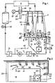
- a condensate pump 8 conveys the condensate through a condensate cleaning system 9, from where it reaches the low-pressure preheater 11 via the Hotwell control valve 10, only one of which is symbolically shown.
- the feed pump 12 conveys the feed water to the steam generator 1 via the high pressure preheaters 13, only one of which is shown.
- the air cooler zones 35 are accommodated within the tube bundle 5 in the condensation zone, from which the non-condensable gases are drawn off together with a certain amount of steam via vent lines 36. This is done with the vacuum pump 37. Before the latter, an additional condenser 38 is arranged in the vent line, which is operated with secondary cooling water 39, which is preferably colder than the main cooling water for the condenser 3. This additional condenser 38 is dewatered via a siphon 40 in the main condenser 3rd
- the condensate collection vessel 6 is separated from the condensation space 4 by an intermediate floor 28. Both rooms are connected to each other by a steam equalization opening 29.
- the condensate formed on the tube bundles 5 initially collects on the intermediate floor 28 and then flows vertically downwards into the vessel 6 via a slot-shaped condensate drain opening 23 directly adjacent to the wall of the condenser.
- the condensate collects on the condenser floor, which is integrated into a by means of a weir 14 larger compartment 15 and a smaller compartment 16 is divided.
- the smaller compartment 16 is the actual Hotwell and is provided with the sump 17.
- level triangles 7 and 7 denote the water level in the actual collecting vessel. in the hotwell.
- the hotwell is against the large compartment 15 via boundary walls 18 and 19 sealed off.
- the boundary walls extend from the bottom of the collecting vessel to the underside of the intermediate bottom 28.
- an actual flow channel 24 is formed with the walls 20, 21 and 22, which ends at the weir 14.
- the flow-limiting walls also extend from the bottom of the collecting vessel to the underside of the intermediate floor 28. The actual degassing is carried out in this channel 24.
- the weir is dimensioned so that the water height in the flow channel and thus in the collecting vessel is approx. 1000 mm.
- the total height between the condenser floor and the intermediate floor is approximately 1400 mm, so that between the water level 7, the intermediate floor 28 and the walls there is a completely enclosed rinsing steam chamber 25 with a clear height of 400 mm.
- the already mentioned vapor compensation opening 29 is provided in the intermediate floor 28.
- the intermediate floor 28 runs below the entire condensation zone, in order to avoid that the condensate raining down from the bundles mixes with the largely degassed condensate in the collecting vessel, only the flow channel can be covered.
- the condensate drainage channel 23 running across the entire condenser width can then be dispensed with and it makes sense to combine the steam compensation opening 29 with the drainage channel for the condensate in a common apparatus.
- the opening 29 is designed as a chimney (Fig. 1). It is protected from the top by a plate against dripping condensate; Condensate entrained by the steam flow in chamber 44 is separated on a lower baffle plate.
- the circulated minimum amount of condensate in the typical system under consideration is approx. 40 kg / sec.
- the channel width is selected accordingly.
- steam bubbles which are generated in steam separation means 26.
- These agents are preferably commercially available two-phase nozzles, which are acted upon with both liquid and steam. They are dimensioned so that vapor bubbles with a diameter of approx. 1 mm form at the outlet mouth. Steam bubbles with a diameter between 0.5 and 2 mm are generally suitable.
- a plurality of these nozzles are arranged in the flow channel 24 at a distance of approximately 800 to 1000 mm. They are arranged one behind the other in the direction of flow of the condensate, starting in the inflow region and ending in the region of the weir 14.
- the nozzles are attached at a depth between 500 and 1000 mm, preferably approximately 900 mm, below the water level 7.
- Their outlet mouth is directed horizontally, among other things, to extend the dwell time when rising through the condensate.
- the individual nozzles are fed via a rotating double pipe, the water pipe 27 of which branches off from the feed water line via a line 30 - and advantageously behind the condensate pump 8. In the present case, this takes place between the hotwell control valve 10 and the condensate cleaning system 9, so that purified water is used in each case.
- a throttle element 31 is arranged in the water line 30 in order to throttle the prevailing water pressure down to the pressure upstream of the nozzle which is necessary for the generation of bubbles.
- the steam pipe 32 of the circulating double pipe is connected to a pressure line 33 corresponding pressure, which pressure is also provided in a reducing member 34.
- the steam source itself can be of several types.
- auxiliary steam system (not shown) that is already active before the actual steam generation in the boiler 1 can be tapped, which is required for the provision of preservation steam and / or stuffing box steam.
- Other possible sources of steam are live steam or bleed steam from the turbine system 2, it only being necessary to ensure that low-oxygen steam is sprayed in each case.
- the degassing process will now be described with reference to the start-up process of the plant. It is assumed that the system is completely filled, i.e. H. the entire preheater line is filled up immediately before the closed steam generator isolating valve 43.
- the condensate pump now rolls over the minimum quantity line 41 with the minimum quantity of condensate pump, i. H. about 20% of the nominal load, the water around. Due to the fact that the total amount of water repeatedly acts on the condensate cleaning system 9, approximately 10 cycles are sufficient to separate out the corrosion products which have formed and accumulated in the feed water circuit before the low-pressure preheaters 11, in particular during the downtime of the system.
- the feed water is of the required quality, it has been enriched with oxygen during the multiple circulation, since not all air can be removed from the circuit on the occasion of the start-up vacuum.
- the two-phase nozzles 26 simultaneously with water and steam from the tubes 27, respectively. 32 fed.
- the pressure in front of the nozzle is between 1.5 and 2.5 bar depending on the type used. Due to the pressure reduction in the spray nozzles, part of the introduced condensate evaporates and together with the introduced steam forms the vapor bubbles of the desired diameter, which rise homogeneously through the condensate.
- the actual steam consumption for the formation of bubbles is relatively low.
- the mass ratio steam / water is in the order of 0.015 to 0.025. With the degassing of approx. 40 kg / sec of condensate, this corresponds to a consumption of approximately 7 to 8 gr of steam per second.
- the feed water degassing has been carried out to the required level, for example has an oxygen content of less than 10 ppb, which can be demonstrated by simple measurement in or after the condensate collection vessel 6, the primary cleaning and degassing phase is thus ended.
- the steam generator 1 is then filled with subsequent steam generation.
- the venting capacity of the vacuum pump is effectively increased. This is particularly advantageous because the vacuum pump usually has an insufficient suction power during low-load operation.
- the condensate deposited in the additional condenser 38 is returned to the main condenser; Due to the pressure difference between the additional condenser 38 and the condensation chamber 4, the siphon 40 is arranged in the line provided for this purpose.
- the tube bundles 5 still contain air fields in which the resulting condensate is enriched with oxygen because the suction capacity is still not sufficient.
- post-degassing is required, which is carried out in the same way in the collecting vessel.
- live steam or bleed steam can expediently be introduced into the steam line 32.
- the post-degassing remains in operation for up to about 40% of the load, that is, until the vacuum pump 37 is able to avoid air accumulation by itself.
- bad condenser concepts which have zones with unavoidable air pockets even during normal load operation, you will not be able to avoid permanent post-degassing operation. It should only be mentioned in passing that the amount of steam required for this is not available for expansion in the turbine or for preheating.
- the invention is not limited to the application shown and described.
- a vertical injection could also be taken into account if the required water depth is then available. This could be the case for systems in which the Degassing a separate module is used, for example because there is not enough space above the condenser floor due to space constraints.
- Flow channels in a meandering shape are particularly conceivable in so-called above-floor arrangements in which the condenser bottom itself serves as a level-controlled hotwell.
- the condensate can be circulated with the minimum amount of the feed pump 12 via the (dashed) line 52 on the occasion of the primary degassing. This also eliminates those corrosion products in the condensate cleaning system 9 which have accumulated in the low-pressure preheaters 11.
Landscapes
- Engineering & Computer Science (AREA)
- Mechanical Engineering (AREA)
- General Engineering & Computer Science (AREA)
- Chemical & Material Sciences (AREA)
- Chemical Kinetics & Catalysis (AREA)
- Combustion & Propulsion (AREA)
- Water Supply & Treatment (AREA)
- Physics & Mathematics (AREA)
- Thermal Sciences (AREA)
- Degasification And Air Bubble Elimination (AREA)
- Physical Water Treatments (AREA)
- Engine Equipment That Uses Special Cycles (AREA)
Description
Die Erfindung betrifft eine Einrichtung zum Entgasen des Kondensates im Kreislauf einer Stromerzeugungsanlage, die im Hauptkreis im wesentlichen aus Dampferzeuger, Turbine, Kondensator, Niederdruck- und Hochdruckvorwärmer und den erforderlichen Zirkulationspumpen besteht.The invention relates to a device for degassing the condensate in the circuit of a power generation system, which in the main circuit consists essentially of steam generator, turbine, condenser, low pressure and high pressure preheater and the necessary circulation pumps.
Im Speisewasser gelöster Sauerstoff, gelöstes Kupfer sowie weitere vom Speisewasser mitgeführte Korrosionsprodukte wurden als die Förderer der Korrosion in Dampferzeugern von Druckwasserreaktor-Anlagen identifiziert. Daher sind in jüngster Zeit grosse Bestrebungen im Gange, den Sauerstoffgehalt im Speisewasser möglichst tief zu halten, gelöstes Kupfer durch Ersatz aller Rohre aus Kupferlegierungen aus dem Speisewasserkreislauf zu eliminieren und Korrosionsprodukte vor dem Dampferzeuger auszuscheiden. Dies umso mehr, als der Ersatz der Dampferzeuger für ein Kraftwerk der 1000 MW-Klasse zu Kosten von ca. 100 Mio. $ führt. Eine Reduktion des Sauerstoffgehaltes im Speisewasser vermindert zudem die Korrosion des Speisewasserstranges und der VorwärmerOxygen dissolved in the feed water, dissolved copper and other corrosion products carried by the feed water were identified as the promoters of corrosion in steam generators of pressurized water reactor systems. Therefore, great efforts have recently been made to keep the oxygen content in the feed water as low as possible, to eliminate dissolved copper by replacing all pipes made of copper alloys from the feed water circuit and to remove corrosion products in front of the steam generator. All the more so since the replacement of the steam generator for a power plant of the 1000 MW class leads to costs of approx. $ 100 million. A reduction in the oxygen content in the feed water also reduces the corrosion of the feed water line and the preheater
Sauerstoff wird im Speisewasser resp. im Kondensat gelöst, wenn Luft mit dem Wasser in Berührung kommt. Dies ist z. B. der Fall:
- - Beim Kaltstart einer Anlage, da vor dem Füllen mit Kondensat alle Anlageteile unter Luftdruck stehen, und durch die Anfahrevakuierung nicht alle Luft aus dem Speisewasser/Dampfkreislauf entfernt werden kann;
- - bei Schwachlastbetrieb, da die Absaugekapazität der Vakuumpumpen für die einfallende Luft aus wirtschaftlichen Erwägungen und aus Gründen der Realisierbarkeit nicht so gross gewählt werden kann, dass alle Teile des Kondensatorbündels ausreichend mit Dampf gespült werden;
- - bei normalem Lastbetrieb, weil trotz ausreichender Absaugekapazität die Luftkonzentration gegen das Ende der Kondensation, d. h. gegen den Luftkühler hin, so gross wird, dass messbare Sauerstoffkonzentrationen resultieren;
- - weil auch bei normalem Lastbetrieb sehr viele Kondensator-Konzepte Zonen aufweisen, in denen es zu Luftansammlungen kommt;
- - weil bei der Zusatzwasseraufbereitung das gereinigte entsalzte Zusatzwasser mit Luft durchwaschen wird, um Kohlendioxyd auszutreiben, und daher zu 100 % mit Luft gesättigt wird.
- - When starting a system cold, since all parts of the system are under air pressure before filling with condensate, and due to the start-up vacuum, not all air can be removed from the feed water / steam circuit;
- - in low-load operation, since the suction capacity of the vacuum pumps for the incoming air cannot be chosen so large for economic reasons and for reasons of feasibility that all parts of the condenser bundle are sufficiently rinsed with steam;
- - During normal load operation, because despite sufficient suction capacity, the air concentration towards the end of the condensation, ie towards the air cooler, becomes so great that measurable oxygen concentrations result;
- - Because even during normal load operation, a large number of capacitor concepts have zones in which air accumulates;
- - Because during the make-up water treatment, the cleaned, desalinated make-up water is washed through with air to drive off carbon dioxide and is therefore 100% saturated with air.
Kupfer wird z. B. bei Anwesenheit von Ammoniak und Sauerstoff aus den benetzten Metalloberflächen von Kupferlegierungen gelöst oder aber durch Erosion oder Korrosion dieser Metalloberflächen ins Speisewasser eingetragen. Korrosionsprodukte sowie weitere Verunreinigungen werden hauptsächlich bei Stillstandsperioden im Speisewasser angesammelt.Copper is e.g. B. in the presence of ammonia and oxygen from the wetted metal surfaces of copper alloys or introduced into the feed water by erosion or corrosion of these metal surfaces. Corrosion products and other contaminants are mainly accumulated in the feed water during periods of standstill.
Die Fachwelt ist derzeit der Auffassung, dass ein maximaler Sauerstoffgehalt von < 10 ppb (Teile pro Milliarde) über den gesamten Betriebsbereich der Anlage anstrebenswert ist.Experts are currently of the opinion that a maximum oxygen content of <10 ppb (parts per billion) over the entire operating range of the system is desirable.
In guten Kondensatoren, d. h. solchen mit nachgewiesener gure Entgasungsfähigkeit, wurden im Lastbereich zwischen 40 bis 100 % Sauerstoffgehalte von < 5 ppb im Kondensat festgestellt. Das Zusatzwasser wird dabei im Kondensator selbst entgast. Beim Kaltstart einer solchen Anlage und im Schwachlastbetrieb wurden jedoch etwa 70 ppb im Hotwell des Kondensators gemessen. Diese Sauerstoffgehalte müssten weiter abgebaut werden.In good capacitors, i.e. H. Those with proven good degassing ability were found in the load range between 40 to 100% oxygen contents of <5 ppb in the condensate. The make-up water is degassed in the condenser itself. When cold starting such a system and in low-load operation, however, about 70 ppb was measured in the hotwell of the capacitor. These oxygen levels would have to be reduced further.
Zur Lösung des Korrosionsproblems wurden am EPRI Kondensator-Seminar im Juni 1983 in Orlando, Florida folgende Vorschläge diskutiert:
- a) Anfahrentgasung und Schwachlastentgasung durch Versprühung des rezirkulierten Speisewassers über die Rohre des Kondensators. Diese Idee führt erst dann zum Erfolg, wenn die verfügbare Saugerkapazität grösser als die für Sauerstoffgehalte von < 10 ppb notwendige Saugerkapazität wird. Dies kann erst bei Lasten ab 30 bis 40 % erwartet werden. Denn Versprühung von aufgewärmtem Kondensat über die Bündel des Kondensators hat erst dann den gewünschten Effekt, wenn auf dem gesamten Weg dieses Kondensates keine Zonen grösserer Luftkonzentrationen durchlaufen werden. Eine Reinigung des gesamten Speisewasserkreislaufes ist durch die Kondensatrezirkulation ebenfalls nicht möglich.
- b) Vergrösserung der Saugerkapazität im Schwachlastbereich durch Reduktion des Dampfgehaltes im Saugstrom mittels Mischkondensation. Mischkondensation kann jedoch nur einen Teil des Wasserdampfes aus dem Sauggemisch kondensieren, der Sauger muss immer noch alle Luft absaugen, was im allgemeinen erst bei Kondensatordrücken möglich ist, die über dem "Leerlaufdruck" des Kondensators liegen.
- c) Nachentgasung des Kondensates im Hotwell durch Rieseleinbauten. Bei derartigen Rieselanlagen muss genügend Höhe für die Einbauten zur Verfügung stehen.
- d) Nachentgasung des Kondensates im Hotwell durch Dampfeinblasen unter dem Wasserniveau. Für die Dampfeinblasung ist eine genügend grosse Kondensatüberdeckung sowie eine genügend feine Dampfverteilung im Kondensat erforderlich.
- a) Start-up degassing and low-load degassing by spraying the recirculated feed water through the pipes of the condenser. This idea only leads to success if the available suction capacity becomes greater than the suction capacity required for oxygen contents of <10 ppb. This can only be expected for loads from 30 to 40%. Spraying warmed-up condensate over the bundle of the condenser only has the desired effect if no zones of greater air concentrations are passed through the entire path of this condensate. It is also not possible to clean the entire feed water circuit through the condensate recirculation.
- b) Increasing the suction capacity in the low load range by reducing the steam content in the suction flow by means of mixed condensation. However, mixed condensation can only condense a part of the water vapor from the suction mixture, the suction device still has to extract all air, which is generally only possible at condenser pressures that are above the "idling pressure" of the condenser.
- c) Post-degassing of the condensate in the hotwell using trickle internals. With such trickle systems, sufficient height must be available for the internals.
- d) Post-degassing of the condensate in the hotwell by blowing in steam below the water level. A sufficiently large condensate cover and a sufficiently fine steam distribution in the condensate are required for the steam injection.
Eine Einrichtung der eingangs genannten Art ist bekannt aus der EP-A-0 152 920. Dort wird im Sammelgefäss des Kondensators mittels Wänden ein Strömungskanal für das Kondensat gebildet, in dem zwei Gruppen von Dampfeinführungen unterhalb des Wasserspiegels vorgesehen sind. Eine erste Gruppe befindet sich am Kanalanfang. Dort wird das Kondensat behandelt. Das dabei anfallende Dampf-Sauerstoff-Gemisch gelangt aus dem oben offenen Kanal in den Kondensationsraum, aus dem es abgezogen wird. Anschliessend strömt das Kondensat in den schikaneförmigen Strömungskanal, der nach oben abgeschlossen ist. Innerhalb des rundum geschlossenen Kanals befindet sich eine zweite Gruppe von Dampfeinführungen zur Nachentgasung des Kondensates. Das dort abgeschiedene Gemisch wird über eine unmittelbar oberhalb der Gruppe angeordnete Auslassöffnung in den Kondensationsraum abgezogen.A device of the type mentioned at the outset is known from EP-A-0 152 920. There, a flow channel for the condensate is formed in the collecting vessel of the condenser by means of walls, in which two groups of steam inlets are provided below the water level. A first group is at the beginning of the channel. The condensate is treated there. The resulting steam-oxygen mixture passes from the open-topped duct into the condensation chamber, from which it is drawn off. The condensate then flows into the baffle-shaped flow channel, which is closed at the top. A second group of steam inlets for post-degassing of the condensate is located inside the completely closed duct. The mixture separated there is drawn off into the condensation chamber via an outlet opening arranged directly above the group.
Bei einer andern, aus der EP-A-0 134457 bekannten Einrichtung wird vor Aufnahme der Dampferzeugung in einer nuklear beheizten Stromerzeugungsanlage unterhalb des Wasserspiegels im Kondensatsammelgefäss ein Mittel zur Entgasung über Sprühdüsen in das Kondensat eingeführt. Dieses Mittel kann Speisewasser, Hilfsdampf oder ein Inertgas sein. Das Mittel steigt im Kondensat hoch und bildet in einer Entgasungskammer unter Verdrängung der darin befindlichen Luft ein Polster, welches der Sauerstoff-Entgasung förderlich ist. Der bei der Entgasung entstehende Dampf wird in einem Zusatzkondensator niedergeschlagen.In another device known from EP-A-0 134457, a means for degassing is introduced into the condensate via spray nozzles before the steam generation begins in a nuclear-heated power plant below the water level in the condensate collecting vessel. This agent can be feed water, auxiliary steam or an inert gas. The agent rises in the condensate and forms a cushion in a degassing chamber, displacing the air therein, which is conducive to oxygen degassing. The steam generated during the degassing is deposited in an additional condenser.
Der in den Patentansprüchen gekennzeichneten Erfindung liegt die Aufgabe zugrunde, die insbesondere durch Dampferzeuger-Korrosionsprobleme bedingte Kondensat- resp. Speisewasserentgasung vorgängig der normalen Betriebslast zu bewerkstelligen und für Teillast zu optimieren.The invention characterized in the claims is based on the object, in particular due to steam generator corrosion problems condensate or. Feedwater degassing must be carried out in advance of the normal operating load and optimized for partial load.
Mit der Erfindung wird damit eine besonders günstige Lösung gefunden, bei welcher die Zeit für die Entgasung vor dem Anlagenstart auf ein Minimum reduziert wird und bei welcher im gesamten Betriebsbereich entgastes Speisewasser bereitgestellt ist, ohne spürbare Verluste am Kondensatorvakuum in Kauf nehmen zu müssen.With the invention, a particularly favorable solution is thus found in which the time for degassing before starting the system is reduced to a minimum and in which degassed feed water is provided in the entire operating range without having to accept appreciable losses in the condenser vacuum.
In der Zeichnung ist ein Ausführungsbeispiel der Erfindung schematisch dargestellt.In the drawing, an embodiment of the invention is shown schematically.
Es zeigen:
- Fig. 1 ein stark vereinfachtes Anlagenschema,
- Fig. 2 einen Schnitt im vergrössertem Maßstab durch den Kondensator nach Linie A - A in Fig. 1.
- 1 is a highly simplified system diagram,
- FIG. 2 shows a section on an enlarged scale through the capacitor according to line AA in FIG. 1.
Alle für das Verständnis der Erfindung unwesentlichen Anlageteile, wie beispielsweise der eigentliche Dampfkreis und die zahlreichen selbstverständlichen Absperrarmaturen in den Leitungen sind nicht gezeigt. Die Strömungsrichtung der diversen Medien ist jeweils mit Pfeilen angegeben.All parts of the system which are insignificant for understanding the invention, such as, for example, the actual steam circuit and the numerous self-evident shut-off valves in the lines, are not shown. The direction of flow of the various media is indicated with arrows.
Mit 1 sei ein nuklear beheizter Dampferzeuger bezeichnet. Im Normalbetrieb wird der darin produzierte Sattdampf in der nicht näher dargestellten Turbinenanlage 2 bis auf Kondensatordruck entspannt. Im Kondensator 3 wird der Dampf im Kondensationsraum 4 an den wassergekühlten Rohrbündeln 5 niedergeschlagen; das Kondensat wird im Kondensatsammelgefäss 6 aufgefangen. Eine Kondensatpumpe 8 fördert das Kondensat durch eine Kondensatsreinigungsanlage 9, von wo es über das Hotwell-Regelventil 10 in die Niederdruckvorwärmer 11 gelangt, von denen nur ein Exemplar symbolisch dargestellt ist. Für das vorliegende Beispiel wird ferner angenommen, dass es sich um eine Anlage ohne Mischvorwärmer und somit auch ohne die übliche Mischvorwärmer-Entgaserstufe handelt, eine Anlage demnach, wie sie häufig in den USA anzutreffen ist. Aus den Niederdruckvorwärmern fördert die Speisepumpe 12 das Speisewasser über die Hochdruckvorwärmer 13, von denen auch nur ein Exemplar dargestellt ist, zum Dampferzeuger 1.1 is a nuclear-heated steam generator. In normal operation, the saturated steam produced therein is expanded to the condenser pressure in the
Innerhalb der Rohrbündel 5 in der Kondensationszone sind die an sich bekannten Luftkühlerzonen 35 untergebracht, aus denen die nicht kondensierbaren Gase zusammen mit einem gewissen Dampfanteil über Entlüftungsleitungen 36 abgezogen werden. Dies geschieht mit der Vakuumpumpe 37. Vor letzterer ist ein zusätzlicher Kondensator 38 in der Entlüftungsleitung angeordnet, der mit Nebenkühlwasser 39 betrieben wird, das vorzugsweise kälter ist als das Hauptkühlwasser für den Kondensator 3. Entwässert wird dieser Zusatzkondensator 38 über ein Siphon 40 in den Hauptkondensator 3.The air
Das Kondensatsammelgefäss 6 ist vom Kondensationsraum 4 durch einen Zwischenboden 28 abgetrennt. Beide Räume sind durch eine Dampfausgleichsöffnung 29 miteinander verbunden. Das an den Rohrbündeln 5 entstehende Kondensat sammelt sich zunächst auf dem Zwischenboden 28 und fliesst dann über eine an die Wandung des Kondensators unmittelbar angrenzende, schlitzförmige Kondensatabflussöffnung 23 senkrecht abwärts ins Gefäss 6. Das Kondensat sammelt sich am Kondensatorboden, der mittels eines Wehrs 14 in ein grösseres Kompartiment 15 und ein kleineres Kompartiment 16 unterteilt ist. Das kleinere Kompartiment 16 ist der eigentliche Hotwell und ist mit dem Sumpf 17 versehen. Mit der Unterteilung und dem Überlauf werden zum einen strömungsgerechte Zustrombedingungen zur Kondensatpumpe 8 geschaffen und zum andern wird die Niveauregulierung im Hotwell nicht beeinträchtigt. Die Niveaudreiecke 7 und 7' bezeichnen den Wasserspiegel jeweils im eigentlichen Sammelgefäss resp. im Hotwell.The condensate collection vessel 6 is separated from the condensation space 4 by an
Der Hotwell ist über Begrenzungswände 18 und 19 gegen das grosse Kompartiment 15 abgeschottet. Die Begrenzungswände erstrecken sich vom Boden des Sammelgefässes bis zur Unterseite des Zwischenbodens 28.The hotwell is against the
Im grossen Kompartiment ist das Kondensat zwangsgeführt. Hierzu ist mit den Wänden 20, 21 und 22 ein eigentlicher Strömungskanal 24 gebildet, der am Wehr 14 endet. Die strömungsbegrenzenden Wände erstrecken sich ebenfalls vom Boden des Sammelgefässes bis zur Unterseite des Zwischenbodens 28. In diesem Kanal 24 wird die eigentliche Entgasung vorgenommen.The condensate is positively guided in the large compartment. For this purpose, an
Die für eine bestmögliche Entgasung günstigsten Abmessungen seien anhand eines Zahlenbeispieles erläutert: Das Wehr ist so bemessen, dass die Wasserhöhe im Strömungskanal und damit im Sammelgefäss ca. 1000 mm beträgt. Die Gesamthöhe zwischen Kondensatorboden und Zwischenboden beträgt ca. 1400 mm, so dass zwischen Wasserniveau 7, Zwischenboden 28 und Wänden eine rundum geschlossene Spüldampfkammer 25 mit 400 mm lichter Höhe entsteht.The most favorable dimensions for the best possible degassing are explained using a numerical example: the weir is dimensioned so that the water height in the flow channel and thus in the collecting vessel is approx. 1000 mm. The total height between the condenser floor and the intermediate floor is approximately 1400 mm, so that between the
Im Bereich des Einlaufes des Strömungskanals ist die bereits genannte Dampfausgleichsöffnung 29 im Zwischenboden 28 vorgesehen. In Abweichung zur dargestellten Konfiguration, bei welcher der Zwischenboden 28 unterhalb der ganzen berohrten Kondensationszone verläuft - um zu vermeiden, dass sich das aus den Bündeln niederregnende Kondensat mit dem weitgehend entgasten Kondensat im Sammelgefäss vermischt - kann auch lediglich der Strömungskanal überdacht sein. Auf die über die ganze Kondensatorbreite verlaufende Kondensatabflussrinne 23 kann dann verzichtet werden und es bietet sich an, die Dampfausgleichsöffnung 29 mit der Abflussrinne für das Kondensat in einem gemeinsamen Apparat zu kombinieren.In the area of the inlet of the flow channel, the already mentioned
Im dargestellten Fall ist die Öffnung 29 als Kamin ausgebildet (Fig. 1). Gegen herabtropfendes Kondensat ist sie nach oben hin durch eine Platte geschützt; von der Dampfströmung in der Kammer 44 mitgerissenes Kondensat wird an einer unteren Prallplatte abgeschieden.In the illustrated case, the
Die umgewälzte Kondensatminimalmenge der betrachteten typischen Anlage betrage ca. 40 kg/sec. Um zwecks optimaler Entgasung im Strömungskanal eine Kondensatgeschwindigkeit von 0,2 m pro Sekunde zu erzielen, wird die Kanalbreite entsprechend gewählt.The circulated minimum amount of condensate in the typical system under consideration is approx. 40 kg / sec. In order to achieve a condensate velocity of 0.2 m per second in the flow channel for optimal degassing, the channel width is selected accordingly.
Die eigentliche Entgasung erfolgt mittels Dampfblasen, die in Dampfzerteilungsmitteln 26 erzeugt werden. Diese Mittel sind vorzugsweise handelsübliche Zweiphasendüsen, die sowohl mit Flüssigkeit als auch mit Dampf beaufschlagt werden. Sie sind so bemessen, dass sich an der Austrittsmündung Dampfblasen mit einem Durchmesser von ca. 1 mm bilden. Geeignet sind grundsätzlich Dampfblasen mit einem Durchmesser zwischen 0,5 und 2 mm.The actual degassing takes place by means of steam bubbles which are generated in steam separation means 26. These agents are preferably commercially available two-phase nozzles, which are acted upon with both liquid and steam. They are dimensioned so that vapor bubbles with a diameter of approx. 1 mm form at the outlet mouth. Steam bubbles with a diameter between 0.5 and 2 mm are generally suitable.
Im Strömungskanal 24 ist eine Mehrzahl dieser Düsen angeordnet im Abstand von etwa 800 bis 1000 mm. In Strömungsrichtung des Kondensats sind sie hintereinander angeordnet, beginnend im Einströmbereich und endend im Bereich des Wehrs 14. Die Düsen sind in einer Tiefe zwischen 500 und 1000 mm, vorzugsweise ca. 900 mm unterhalb des Wasserniveaus 7 befestigt. Ihre Austrittsmündung ist jeweils horizontal gerichtet, unter anderem, um die Verweilzeit beim Aufsteigen durch das Kondensat zu verlängern.A plurality of these nozzles are arranged in the
Die Anspeisung der einzelnen Düsen erfolgt über ein umlaufendes Doppelrohr, dessen Wasserrohr 27 über eine Leitung 30 vom Speisewasserstrang - und zwar vorteilhafterweise hinter der Kondensatpumpe 8 - abzweigt. Im vorliegenden Fall geschieht dies zwischen dem Hotwellregelventil 10 und der Kondensatreinigungsanlage 9, so dass jeweils gereinigtes Wasser zur Anwendung gelangt. In der Wasserleitung 30 ist ein Drosselorgan 31 angeordnet, um den herrschenden Wasserdruck auf den für die Blasenerzeugung erforderlichen Druck vor Düse herab zu drosseln. Das Dampfrohr 32 des umlaufenden Doppelrohres ist an eine Dampfleitung 33 entsprechenden Druckes angeschlossen, wobei der Druck ebenfalls in einem Reduzierorgan 34 bereitgestellt wird. Die Dampfquelle selbst kann mehrfacher Art sein. So kann beispielsweise das vor der eigentlichen Dampferzeugung im Kessel 1 bereits aktive Hilfsdampfsystem (nicht dargestellt) angezapft werden, welches für die Bereitstellung von Konservierungsdampf und/oder Stopfbüchsendampf erforderlich ist. Andere mögliche Dampfquellen sind Frischdampf oder Anzapfdampf aus der Turbinenanlage 2, wobei lediglich darauf zu achten ist, dass jeweils sauerstoffarmer Dampf eingesprüht wird.The individual nozzles are fed via a rotating double pipe, the
Das Entgasungsverfahren wird nunmehr anhand des Anfahrvorgangs der Anlage beschrieben. Es wird dabei angenommen, dass die Anlage vollständig gefüllt ist, d. h. die ganze Vorwärmerstrasse ist bis unmittelbar vor die verschlossene Dampferzeuger-Isolierarmatur 43 aufgefüllt. Die Kondensatpumpe wälzt nun über die Mindestmengenleitung 41 mit der Kondensatpumpen-Mindestmenge, d. h. etwa 20 % der Nennlastmenge, das Wasser um. Dadurch, dass die gesamte Wassermenge die Kondensatreinigungsanlage 9 wiederholt beaufschlagt, genügen etwa 10 Umläufe, um die Korrosionsprodukte auszuscheiden, die sich im Speiserwasserkreislauf vor den Niederdruckvorwärmern 11 insbesondere während der Stillstandperiode der Anlage gebildet und angesammelt haben.The degassing process will now be described with reference to the start-up process of the plant. It is assumed that the system is completely filled, i.e. H. the entire preheater line is filled up immediately before the closed steam
Wenn nun zwar vom Standpunkt der Reinheit das Speisewasser die erforderliche Qualität aufweist, so hat es sich doch während der mehrfachen Zirkulation mit Sauerstoff angereichert, da anlässlich der Anfahrevakuierung nicht alle Luft aus dem Kreislauf entfernt werden kann.If, from the point of view of purity, the feed water is of the required quality, it has been enriched with oxygen during the multiple circulation, since not all air can be removed from the circuit on the occasion of the start-up vacuum.
Die eigentliche thermische Entgasung, bewirkt durch Energiezufuhr in das Kondensat, kann nun erfolgen. Hierzu werden die Zweiphasendüsen 26 gleichzeitig mit Wasser und Dampf aus den Rohren 27 resp. 32 angespeist. Der Druck vor Düse beträgt je nach verwendetem Typ zwischen 1,5 bis 2,5 bar. Durch den in den Sprühdüsen erfolgenden Druckabbau verdampft der Teil des eingeführten Kondensates und bildet zusammen mit dem eingeführten Dampf die Dampfblasen vom gewünschten Durchmesser, die homogen durch das Kondensat aufsteigen.The actual thermal degassing, caused by supplying energy to the condensate, can now take place. For this purpose, the two-
Es sei nochmals daran erinnert, dass für die vorgegebene Wassertiefe ein Blasendurchmesser von ca. 1 mm optimal ist, da einerseits dann die Verweilzeit nicht lang genug ist, um Blasen durch den Sumpf 17 aus dem Kondensator herauszuführen, andererseits jedoch lang genug ist, um die erforderliche Sauerstoffdesorption durchzuführen. Die Kinematik dieser Sauerstoffdesorption ist hinlänglich bekannt und es braucht hier nicht darauf eingegangen zu werden.It should be remembered again that a bubble diameter of approx. 1 mm is optimal for the given water depth, since on the one hand the dwell time is not long enough to lead bubbles out of the condenser through the
Der eigentliche Dampfverbrauch für die Blasenbildung ist relativ gering. Das Massenverhältnis Dampf/Wasser bewegt sich in der Grössenordnung 0,015 bis 0,025. Bei der Entgasung von ca. 40 kg/sec Kondensat entspricht dies einem Verbrauch von etwa sekundlich 7 bis 8 gr Dampf.The actual steam consumption for the formation of bubbles is relatively low. The mass ratio steam / water is in the order of 0.015 to 0.025. With the degassing of approx. 40 kg / sec of condensate, this corresponds to a consumption of approximately 7 to 8 gr of steam per second.
Gelangen die Blasen nach einer Verweilzeit zwischen 5 und 10 sec an die Wasseroberfläche, so wird in der Spüldampfkammer 25 ein Dampfpolster geschaffen, welches die bis dahin verbliebene Luft über die Dampfausgleichsöffnung 29 verdrängt. Zusammen mit der Kondensatorentlüftung wird der über die Öffnung 29 abströmende Dampf abgezogen und im Zusatzkondensator 38 niedergeschlagen.If the bubbles reach the water surface after a dwell time of between 5 and 10 seconds, a steam cushion is created in the rinsing
Hier zeigt sich nun der besondere Vorteil der neuen Gegenstromanordnung. Das Kondensat, welches in Richtung Sumpf 17 strömt, wird mehrfach hintereinander mit Dampfblasen bearbeitet, wodurch sein Sauerstoffgehalt sukzessive abnimmt. Hingegen enthält der aus dem Kondensat entweichende und in der Kammer 25 ebenfalls zwangsgeführte Spüldampf im Bereich des Sumpfes 17 die geringste Sauerstoffkonzentration. Im Verlauf seiner Abströmung steigert sich der Sauerstoffgehalt im Spüldampf zunehmend und erreicht seinen Höchstwert vor der ersten Düse 26 im Bereich der Ausgleichsöffnung 29.This shows the special advantage of the new counterflow arrangement. The condensate, which flows in the direction of the
Wenn die Speisewasser-Entgasung auf das erforderliche Niveau erfolgt ist, beispielsweise einen Sauerstoffgehalt geringer als 10 ppb aufweist, was durch einfache Messung im oder nach dem Kondensatsammelgefäss 6 nachzuweisen ist, ist die primäre Reinigungs- und Entgasungsphase damit beendet. Es folgt die Füllung des Dampferzeugers 1 mit anschliessender Dampferzeugung.If the feed water degassing has been carried out to the required level, for example has an oxygen content of less than 10 ppb, which can be demonstrated by simple measurement in or after the condensate collection vessel 6, the primary cleaning and degassing phase is thus ended. The steam generator 1 is then filled with subsequent steam generation.
Die Hochlaufphase beim Anlagenstart und die hierfür erforderliche Umgehung der Turbine sind erfindungsunwesentlich und können im vorliegenden Zusammenhang unberücksichtigt bleiben.The run-up phase at the start of the plant and the bypassing of the turbine required for this are not essential to the invention and can be disregarded in the present context.
Es wird nunmehr angenommen, dass eine gewisse Teillast gefahren wird. Zur Kondensation wird nunmehr gerade die unbedingt erforderliche Kühlwassermenge zirkulieren lassen. Vorzugsweise wird bis zu einer bestimmten Teillast nur ein Teil, beispielsweise eine Hälfte des Kondensators in Betrieb genommen. In diesem Stadium ist nämlich im Kondensationsraum 4 ein möglichst hoher Druck erwünscht, um die Saugkapazität der Vakuumpumpe 37 voll zu erhalten und auszunützen. Dies bedeutet, dass im Kondensationsraum der einströmende Dampf nicht vollständig auskondensiert, sondern den Raum füllt und hierbei die noch vorhandene Luft verdrängt. Das über die Entlüftungsleitungen 36 abgezogene Luftdampfgemisch durchströmt zunächst den Zusatzkondensator 38, der wie bereits erwähnt mit Nebenkühlwasser 39 betrieben wird, das vorzugsweise von tieferer Temperatur ist als das Hauptkühlwasser. Durch die Reduktioin seines Dampfgehaltes im Zusatzkondensator wird die Entlüftungskapazität der Vakuumpumpe wirkungsvoll vergrössert. Dies ist insbesondere deshalb vorteilhaft, weil die Vakuumpumpe bei Schwachlastbetrieb in der Regel eine ungenügende Saugleistung aufweist. Das im Zusatzkondensator 38 niedergeschlagene Kondensat wird in den Hauptkondensator zurückgeführt; in der dafür vorgesehenen Leitung ist infolge des Druckunterschiedes zwischen Zusatzkondensator 38 und Kondensationsraum 4 der Siphon 40 angeordnet.It is now assumed that a certain part load is being driven. For condensation, the absolutely necessary amount of cooling water is now being circulated. Up to a certain partial load, preferably only a part, for example half of the capacitor, is put into operation. At this stage, the highest possible pressure is desired in the condensation chamber 4 in order to fully maintain and utilize the suction capacity of the
In der soeben beschriebenen Betriebsphase enthalten die Rohrbündel 5 indes weiterhin Luftfelder, in denen das entstehende Kondensat mit Sauerstoff angereichert wird, weil die Saugkapazität immer noch nicht ausreicht. Infolgedessen bedarf es einer Nachentgasung, die auf die gleiche Art im Sammelgefäss vorgenommen wird. Hierzu kann zweckmässigerweise Frischdampf oder Anzapfdampf in die Dampfleitung 32 eingeleitet werden.In the operating phase just described, however, the tube bundles 5 still contain air fields in which the resulting condensate is enriched with oxygen because the suction capacity is still not sufficient. As a result, post-degassing is required, which is carried out in the same way in the collecting vessel. For this purpose, live steam or bleed steam can expediently be introduced into the
Es ist zweckmässig, dass die Nachentgasung bis zu etwa 40 % der Last in Betrieb bleibt, solange also, bis die Vakuumpumpe 37 von selbst fähig ist, Luftansammlungen zu vermeiden. Bei schlechten Kondensatorkonzepten allerdings, die auch im normalen Lastbetrieb Zonen mit unvermeidlichen Lufttaschen aufweisen, wird man um einen permanenten Nachentgasungsbetrieb nicht herumkommen. Dass die hierfür benötigte Dampfmenge nicht für die Entspannung in der Turbine oder für die Vorwärmung zur Verfügung steht, sei nur nebenbei erwähnt.It is expedient that the post-degassing remains in operation for up to about 40% of the load, that is, until the
Selbstverständlich ist die Erfindung nicht auf die gezeigte und beschriebene Anwendung beschränkt. So könnte in Abweichung von der beschriebenen horizontalen Dampfblaseneindüsung auch ein senkrechtes Einblasen berücksichtigt werden, falls die dann erforderliche Wassertiefe vorliegt. Dies könnte bei Anlagen der Fall sein, in denen für die Entgasung ein getrenntes Modul verwendet wird, weil beispielsweise infolge Raumzwang nicht ausreichend Platz über dem Kondensatorboden vorhanden ist. Strömungskanäle in Mäanderform sind inbesondere bei sogenannten Überfluranordnungen denkbar, bei denen der Kondensatorboden selbst als niveaugeregelter Hotwell dient. Abweichend zum Beschriebenen kann anlässlich der Primärentgasung das Kondensat mit der Mindestmenge der Speisepumpe 12 über die (gestrichelte) Leitung 52 zirkuliert werden. Hierdurch werden auch jene Korrosionsprodukte in der Kondensatreinigungsanlage 9 ausgeschieden, die sich in den Niederdruckvorwärmern 11 angesammelt haben.Of course, the invention is not limited to the application shown and described. In a departure from the described horizontal vapor bubble injection, a vertical injection could also be taken into account if the required water depth is then available. This could be the case for systems in which the Degassing a separate module is used, for example because there is not enough space above the condenser floor due to space constraints. Flow channels in a meandering shape are particularly conceivable in so-called above-floor arrangements in which the condenser bottom itself serves as a level-controlled hotwell. Contrary to what has been described, the condensate can be circulated with the minimum amount of the
Schliesslich wäre noch denkbar, die Rezirkulation für die Primärentgasung über eine Leitung durchzuführen, die zwischen Hochdruckvorwärmer 13 und Isolierarmatur 43 abzweigt. Damit könnten sämtliche Verunreinigungen aus dem Vorwärmerstrang entfernt werden.Finally, it would also be conceivable to carry out the recirculation for the primary degassing via a line which branches off between the high-
Claims (4)
Applications Claiming Priority (2)
| Application Number | Priority Date | Filing Date | Title |
|---|---|---|---|
| CH4097/85 | 1985-09-20 | ||
| CH409785 | 1985-09-20 |
Publications (2)
| Publication Number | Publication Date |
|---|---|
| EP0215230A1 EP0215230A1 (en) | 1987-03-25 |
| EP0215230B1 true EP0215230B1 (en) | 1989-03-29 |
Family
ID=4269762
Family Applications (1)
| Application Number | Title | Priority Date | Filing Date |
|---|---|---|---|
| EP86109757A Expired EP0215230B1 (en) | 1985-09-20 | 1986-07-16 | Device for degassing the condensate in the circuit of an electricity power unit |
Country Status (11)
| Country | Link |
|---|---|
| US (1) | US4776170A (en) |
| EP (1) | EP0215230B1 (en) |
| KR (1) | KR910003109B1 (en) |
| CA (1) | CA1277877C (en) |
| DE (1) | DE3662612D1 (en) |
| ES (1) | ES2002361A6 (en) |
| FI (1) | FI89678C (en) |
| IN (1) | IN168650B (en) |
| PL (1) | PL154367B1 (en) |
| YU (1) | YU46022B (en) |
| ZA (1) | ZA867137B (en) |
Families Citing this family (15)
| Publication number | Priority date | Publication date | Assignee | Title |
|---|---|---|---|---|
| DE3717521A1 (en) * | 1987-05-04 | 1988-11-17 | Siemens Ag | CONDENSER FOR THE WATER-VAPOR CIRCUIT OF A POWER PLANT, IN PARTICULAR NUCLEAR POWER PLANT |
| JPH04121401A (en) * | 1990-09-12 | 1992-04-22 | Hitachi Ltd | Combined cycle power generating plant |
| US5165237A (en) * | 1991-03-08 | 1992-11-24 | Graham Corporation | Method and apparatus for maintaining a required temperature differential in vacuum deaerators |
| DE4302486A1 (en) * | 1993-01-29 | 1994-08-04 | Abb Patent Gmbh | Method and device for operating the water-steam cycle of a thermal power plant |
| US5495752A (en) * | 1995-02-01 | 1996-03-05 | Townsend; Johnnie V. | Erosion detector for a feed water steam nozzle |
| DE19549139A1 (en) * | 1995-12-29 | 1997-07-03 | Asea Brown Boveri | Process and apparatus arrangement for heating and multi-stage degassing of water |
| US20060266042A1 (en) * | 2005-05-27 | 2006-11-30 | Levine Michael R | Submerged condenser for steam power plant |
| US7895839B2 (en) * | 2005-12-07 | 2011-03-01 | Steven Richard Miller | Combined circulation condenser |
| CN101825360A (en) * | 2010-05-10 | 2010-09-08 | 贵阳铝镁设计研究院 | Method and device for recycling high-pressure dissolved steam exhaust of diluting tank in alumina production |
| CA2742565C (en) * | 2011-06-10 | 2019-04-02 | Imperial Oil Resources Limited | Methods and systems for providing steam |
| CN104093942B (en) * | 2012-02-10 | 2015-10-21 | 阿尔斯通技术有限公司 | Water/vapor recycle and for operating its method |
| CA2780670C (en) | 2012-06-22 | 2017-10-31 | Imperial Oil Resources Limited | Improving recovery from a subsurface hydrocarbon reservoir |
| KR101392140B1 (en) * | 2012-10-12 | 2014-05-07 | 한국수력원자력 주식회사 | Coolant replenishment apparatus for passive auxiliary feedwater system of nuclear power plant |
| CN105793659B (en) * | 2014-01-23 | 2018-05-01 | 三菱日立电力系统株式会社 | Condenser |
| EP3739176A1 (en) * | 2019-05-15 | 2020-11-18 | Siemens Aktiengesellschaft | Power plant and water cleaning method for a once-through water/steam cycle of a power plant |
Family Cites Families (7)
| Publication number | Priority date | Publication date | Assignee | Title |
|---|---|---|---|---|
| US3327774A (en) * | 1965-06-11 | 1967-06-27 | Ingersoll Rand Co | Steam surface condenser |
| FR2229031B1 (en) * | 1973-05-07 | 1975-12-26 | Cem Comp Electro Mec | |
| DE2323533A1 (en) * | 1973-05-10 | 1974-11-28 | Rau Dieter | CURTAIN, IN PARTICULAR ROLLER SHUTTERS, BLINDS OR THE LIKE |
| FR2541441A1 (en) * | 1983-02-22 | 1984-08-24 | Delas Weir Sa | DEVICE FOR DEGASSING CONDENSATES INSTALLED IN A WELL OF ELECTRICAL POWER UNIT CONDENSER |
| CH665451A5 (en) * | 1983-07-19 | 1988-05-13 | Bbc Brown Boveri & Cie | METHOD FOR CLEANING AND DEGASSING THE CONDENSATE / FEED WATER IN A CIRCUIT OF A POWER GENERATION SYSTEM. |
| JPS60169084A (en) * | 1984-02-14 | 1985-09-02 | Hitachi Ltd | Deaeration of condenser and device thereof |
| DE29605135U1 (en) * | 1996-03-20 | 1996-06-13 | Union Special GmbH, 71282 Hemmingen | Sewing machine with a cutting device |
-
1986
- 1986-07-16 DE DE8686109757T patent/DE3662612D1/en not_active Expired
- 1986-07-16 EP EP86109757A patent/EP0215230B1/en not_active Expired
- 1986-08-14 PL PL1986261040A patent/PL154367B1/en unknown
- 1986-08-25 YU YU147986A patent/YU46022B/en unknown
- 1986-09-09 IN IN724/MAS/86A patent/IN168650B/en unknown
- 1986-09-10 US US06/905,511 patent/US4776170A/en not_active Expired - Lifetime
- 1986-09-10 CA CA000517900A patent/CA1277877C/en not_active Expired - Fee Related
- 1986-09-17 KR KR1019860007836A patent/KR910003109B1/en not_active IP Right Cessation
- 1986-09-19 ES ES8602054A patent/ES2002361A6/en not_active Expired
- 1986-09-19 ZA ZA867137A patent/ZA867137B/en unknown
- 1986-09-19 FI FI863799A patent/FI89678C/en not_active IP Right Cessation
Also Published As
| Publication number | Publication date |
|---|---|
| FI89678C (en) | 1993-11-10 |
| ZA867137B (en) | 1987-05-27 |
| YU147986A (en) | 1988-08-31 |
| PL261040A1 (en) | 1987-06-29 |
| FI863799A0 (en) | 1986-09-19 |
| PL154367B1 (en) | 1991-08-30 |
| DE3662612D1 (en) | 1989-05-03 |
| FI89678B (en) | 1993-07-30 |
| US4776170A (en) | 1988-10-11 |
| EP0215230A1 (en) | 1987-03-25 |
| KR910003109B1 (en) | 1991-05-18 |
| IN168650B (en) | 1991-05-11 |
| YU46022B (en) | 1992-12-21 |
| KR870002857A (en) | 1987-04-13 |
| ES2002361A6 (en) | 1988-08-01 |
| CA1277877C (en) | 1990-12-18 |
| FI863799A (en) | 1987-03-21 |
Similar Documents
| Publication | Publication Date | Title |
|---|---|---|
| EP0215230B1 (en) | Device for degassing the condensate in the circuit of an electricity power unit | |
| EP0134457B1 (en) | Steam power plant | |
| DE4240196A1 (en) | Process for cooling and cleaning gas containing ultrafine particles, in particular top gas or generator gas, and device for carrying it out | |
| EP1819909A1 (en) | Method for the operation of a steam power station, especially a steam power station of a power plant used for generating at least electric power, and corresponding steam power station | |
| EP0461515B1 (en) | Device for treating and degasifying of water | |
| DE1642435C3 (en) | Device for obtaining pure water from salt water, brine or brackish water | |
| DE3031454C2 (en) | Sidestream condensation system | |
| DE2949975C2 (en) | Steam generator arrangement for nuclear power plants | |
| EP3448813B1 (en) | Sea water desalination device for desalinating sea water | |
| EP0781583A2 (en) | Process and apparatus for heating and multiple degassing of water | |
| DE69318237T2 (en) | Steam turbine condenser and method of operating the same | |
| DE2922348A1 (en) | Sea water desalination - by atomisation of solar preheated sea water in ascending natural draught and condensn. | |
| EP0463448B1 (en) | Method and apparatus for heating and multiple effect degasification of water | |
| DE3622035A1 (en) | DEVICE FOR CONDENSING WATER VAPOR UNDER PRESSURE AND ITS APPLICATION FOR COOLING A CORE REACTOR AFTER A FASTER | |
| DE1451133C2 (en) | Mixing condenser | |
| EP1576331B1 (en) | Power plant condenser with deaeration/degassing system | |
| DE3405800A1 (en) | METHOD FOR OPERATING A GENERATOR ABSORPTION HEAT PUMP HEATING PLANT FOR SPACE HEATING, HOT WATER HEATING AND THE LIKE AND GENERATOR ABSORPTION HEAT PUMP HEATING SYSTEM | |
| DE19712993A1 (en) | Apparatus for heating and degassing water | |
| EP0452653B1 (en) | Process for gasifying of fine granulated to powdery fuels, with the addition of a combined gas and/or steam turbine plant | |
| DE2608985A1 (en) | Deaerating contact feed heater for steam generating plant - has internal air extraction tubes from zones of max. air concentration (NL 6.9.77) | |
| DE3323120C2 (en) | Process and system for deodorising and / or deacidifying cocoa butter and cocoa butter substitutes | |
| DE441673C (en) | Device for the circulation of fluids in absorption machines | |
| DE102011052430B4 (en) | Steam utilization system | |
| DE3419045C2 (en) | ||
| AT369883B (en) | DEVICE FOR PREPARING WATER |
Legal Events
| Date | Code | Title | Description |
|---|---|---|---|
| PUAI | Public reference made under article 153(3) epc to a published international application that has entered the european phase |
Free format text: ORIGINAL CODE: 0009012 |
|
| AK | Designated contracting states |
Kind code of ref document: A1 Designated state(s): BE CH DE FR GB IT LI NL SE |
|
| RAP1 | Party data changed (applicant data changed or rights of an application transferred) |
Owner name: BBC AKTIENGESELLSCHAFT BROWN, BOVERI & CIE. |
|
| RAP1 | Party data changed (applicant data changed or rights of an application transferred) |
Owner name: BBC BROWN BOVERI AG |
|
| 17P | Request for examination filed |
Effective date: 19870917 |
|
| 17Q | First examination report despatched |
Effective date: 19880315 |
|
| GRAA | (expected) grant |
Free format text: ORIGINAL CODE: 0009210 |
|
| AK | Designated contracting states |
Kind code of ref document: B1 Designated state(s): BE CH DE FR GB IT LI NL SE |
|
| ITF | It: translation for a ep patent filed | ||
| REF | Corresponds to: |
Ref document number: 3662612 Country of ref document: DE Date of ref document: 19890503 |
|
| ET | Fr: translation filed | ||
| GBT | Gb: translation of ep patent filed (gb section 77(6)(a)/1977) | ||
| PLBE | No opposition filed within time limit |
Free format text: ORIGINAL CODE: 0009261 |
|
| STAA | Information on the status of an ep patent application or granted ep patent |
Free format text: STATUS: NO OPPOSITION FILED WITHIN TIME LIMIT |
|
| 26N | No opposition filed | ||
| PGFP | Annual fee paid to national office [announced via postgrant information from national office to epo] |
Ref country code: SE Payment date: 19930614 Year of fee payment: 8 |
|
| ITTA | It: last paid annual fee | ||
| PG25 | Lapsed in a contracting state [announced via postgrant information from national office to epo] |
Ref country code: SE Effective date: 19940717 |
|
| EUG | Se: european patent has lapsed |
Ref document number: 86109757.4 Effective date: 19950210 |
|
| EUG | Se: european patent has lapsed |
Ref document number: 86109757.4 |
|
| PGFP | Annual fee paid to national office [announced via postgrant information from national office to epo] |
Ref country code: NL Payment date: 19950629 Year of fee payment: 10 |
|
| PGFP | Annual fee paid to national office [announced via postgrant information from national office to epo] |
Ref country code: CH Payment date: 19950803 Year of fee payment: 10 |
|
| PG25 | Lapsed in a contracting state [announced via postgrant information from national office to epo] |
Ref country code: LI Effective date: 19960731 Ref country code: CH Effective date: 19960731 |
|
| PG25 | Lapsed in a contracting state [announced via postgrant information from national office to epo] |
Ref country code: NL Effective date: 19970201 |
|
| REG | Reference to a national code |
Ref country code: CH Ref legal event code: PL |
|
| NLV4 | Nl: lapsed or anulled due to non-payment of the annual fee |
Effective date: 19970201 |
|
| REG | Reference to a national code |
Ref country code: GB Ref legal event code: IF02 |
|
| PGFP | Annual fee paid to national office [announced via postgrant information from national office to epo] |
Ref country code: GB Payment date: 20020628 Year of fee payment: 17 |
|
| PGFP | Annual fee paid to national office [announced via postgrant information from national office to epo] |
Ref country code: FR Payment date: 20020711 Year of fee payment: 17 Ref country code: DE Payment date: 20020711 Year of fee payment: 17 |
|
| PGFP | Annual fee paid to national office [announced via postgrant information from national office to epo] |
Ref country code: BE Payment date: 20020724 Year of fee payment: 17 |
|
| BECH | Be: change of holder |
Free format text: 20020130 *ALSTOM |
|
| BECN | Be: change of holder's name |
Effective date: 20020130 |
|
| REG | Reference to a national code |
Ref country code: GB Ref legal event code: 732E |
|
| PG25 | Lapsed in a contracting state [announced via postgrant information from national office to epo] |
Ref country code: GB Free format text: LAPSE BECAUSE OF NON-PAYMENT OF DUE FEES Effective date: 20030716 |
|
| PG25 | Lapsed in a contracting state [announced via postgrant information from national office to epo] |
Ref country code: BE Free format text: LAPSE BECAUSE OF NON-PAYMENT OF DUE FEES Effective date: 20030731 |
|
| BERE | Be: lapsed |
Owner name: *ALSTOM Effective date: 20030731 |
|
| PG25 | Lapsed in a contracting state [announced via postgrant information from national office to epo] |
Ref country code: DE Free format text: LAPSE BECAUSE OF NON-PAYMENT OF DUE FEES Effective date: 20040203 |
|
| GBPC | Gb: european patent ceased through non-payment of renewal fee |
Effective date: 20030716 |
|
| PG25 | Lapsed in a contracting state [announced via postgrant information from national office to epo] |
Ref country code: FR Free format text: LAPSE BECAUSE OF NON-PAYMENT OF DUE FEES Effective date: 20040331 |
|
| REG | Reference to a national code |
Ref country code: FR Ref legal event code: ST |
|
| PG25 | Lapsed in a contracting state [announced via postgrant information from national office to epo] |
Ref country code: IT Free format text: LAPSE BECAUSE OF NON-PAYMENT OF DUE FEES;WARNING: LAPSES OF ITALIAN PATENTS WITH EFFECTIVE DATE BEFORE 2007 MAY HAVE OCCURRED AT ANY TIME BEFORE 2007. THE CORRECT EFFECTIVE DATE MAY BE DIFFERENT FROM THE ONE RECORDED. Effective date: 20050716 |