EP0781041B1 - Procédé d'interpolation de trames progressives - Google Patents
Procédé d'interpolation de trames progressives Download PDFInfo
- Publication number
- EP0781041B1 EP0781041B1 EP96402779A EP96402779A EP0781041B1 EP 0781041 B1 EP0781041 B1 EP 0781041B1 EP 96402779 A EP96402779 A EP 96402779A EP 96402779 A EP96402779 A EP 96402779A EP 0781041 B1 EP0781041 B1 EP 0781041B1
- Authority
- EP
- European Patent Office
- Prior art keywords
- pixel
- frame
- interpolated
- field
- input
- Prior art date
- Legal status (The legal status is an assumption and is not a legal conclusion. Google has not performed a legal analysis and makes no representation as to the accuracy of the status listed.)
- Expired - Lifetime
Links
Images


Classifications
-
- H—ELECTRICITY
- H04—ELECTRIC COMMUNICATION TECHNIQUE
- H04N—PICTORIAL COMMUNICATION, e.g. TELEVISION
- H04N7/00—Television systems
- H04N7/01—Conversion of standards, e.g. involving analogue television standards or digital television standards processed at pixel level
- H04N7/0117—Conversion of standards, e.g. involving analogue television standards or digital television standards processed at pixel level involving conversion of the spatial resolution of the incoming video signal
- H04N7/012—Conversion between an interlaced and a progressive signal
-
- H—ELECTRICITY
- H04—ELECTRIC COMMUNICATION TECHNIQUE
- H04N—PICTORIAL COMMUNICATION, e.g. TELEVISION
- H04N19/00—Methods or arrangements for coding, decoding, compressing or decompressing digital video signals
- H04N19/50—Methods or arrangements for coding, decoding, compressing or decompressing digital video signals using predictive coding
- H04N19/503—Methods or arrangements for coding, decoding, compressing or decompressing digital video signals using predictive coding involving temporal prediction
- H04N19/51—Motion estimation or motion compensation
- H04N19/577—Motion compensation with bidirectional frame interpolation, i.e. using B-pictures
-
- H—ELECTRICITY
- H04—ELECTRIC COMMUNICATION TECHNIQUE
- H04N—PICTORIAL COMMUNICATION, e.g. TELEVISION
- H04N19/00—Methods or arrangements for coding, decoding, compressing or decompressing digital video signals
- H04N19/80—Details of filtering operations specially adapted for video compression, e.g. for pixel interpolation
-
- H—ELECTRICITY
- H04—ELECTRIC COMMUNICATION TECHNIQUE
- H04N—PICTORIAL COMMUNICATION, e.g. TELEVISION
- H04N7/00—Television systems
- H04N7/01—Conversion of standards, e.g. involving analogue television standards or digital television standards processed at pixel level
- H04N7/0127—Conversion of standards, e.g. involving analogue television standards or digital television standards processed at pixel level by changing the field or frame frequency of the incoming video signal, e.g. frame rate converter
- H04N7/0132—Conversion of standards, e.g. involving analogue television standards or digital television standards processed at pixel level by changing the field or frame frequency of the incoming video signal, e.g. frame rate converter the field or frame frequency of the incoming video signal being multiplied by a positive integer, e.g. for flicker reduction
-
- H—ELECTRICITY
- H04—ELECTRIC COMMUNICATION TECHNIQUE
- H04N—PICTORIAL COMMUNICATION, e.g. TELEVISION
- H04N7/00—Television systems
- H04N7/01—Conversion of standards, e.g. involving analogue television standards or digital television standards processed at pixel level
- H04N7/0135—Conversion of standards, e.g. involving analogue television standards or digital television standards processed at pixel level involving interpolation processes
- H04N7/014—Conversion of standards, e.g. involving analogue television standards or digital television standards processed at pixel level involving interpolation processes involving the use of motion vectors
Definitions
- the invention relates to a frame interpolation method. progressive. This process is particularly suitable for converting images with a change in frame rate, by example of an interlaced 50 Hz format into a progressive 75 Hz format. applies in particular in the field of television.
- a good solution is to detect and calculate the movement of different parts of the image, and to calculate the intermediate images thanks to this information; this is the strategy that has been adopted here.
- the main fault of the 100Hz AABB described above is thus corrected while keeping the suppression flicker.
- the deflection of the electron beam ensuring the scanning of the spot is controlled by a system of electromagnets located at the base of the tube.
- a system of electromagnets located at the base of the tube.
- most of the energy absorbed by these electromagnets is returned in the form heat, which quickly makes them unsuitable for their role as it is current consumer technology. It is therefore necessary to reduce the line frequency.
- the upper limit currently reached is 3H.
- the flickering effect is almost invisible at 75 Hz; the screens of some workstations, for example, have a frequency of 72 Hz frame, which makes them much less tiring to watch than a TV screen.
- the invention provides a method for interpolating progressive frames from interlaced frames.
- European patent applications 95 400722.5 (D94 / 128l) and 95 400721.7 (D94 / 128l) on behalf of Thomson Consumer Electronics SA describe methods and devices for converting images of an interlaced 50 Hz format in an interlaced 100 Hz format.
- EP-A-064047 also in the name of Thomson Consumer Electronics Relates to Confidence Measurement Method in motion estimation in an image conversion system.
- the trust placed in a vector is a linear function of the error generated by this vector.
- said linear filters are function of two pixels located respectively in the input frames temporally surrounding the frame to be interpolated, the linear coefficients of interpolation of each pixel corresponding to the ratio of the intervals of time between the frame to be interpolated and the input frame respectively previous and the next input frame.
- the two pixels used for each linear filter are chosen from the group of three pixels used by the filter median temporal.
- the interlaced frames input come from progressive input 25 Hz frequency images and that the frequency of the output frames is 75 Hz, a first output frame being temporally confused with the second frame coming from a first input image, a second output frame being temporally located between said first input frame and the first frame from a second image input, a third output frame being temporally located between the two input frames from said second input image, the coefficients of interpolation used by said time filters are 1/2 for said second output frame.
- coefficients 1/2 allows a significant reduction to be obtained jerky movements compared to the use of coefficients 1/3 and 2/3 taken from the relative position of the second output frame between the two first input frames.
- the pixels of said third output frame are the pixels of the second input image.
- the third output frame actually corresponds to the second input image. This will have possibly undergone the noise reductions mentioned in the description of the particular embodiment example.
- the value of the pixel to be interpolated is the final value obtained by median filtering between firstly the two pixel values obtained by removing, respectively adding the confidence of the motion vector reduced to the pixel divided by a corrective factor to the value of the pixel of the same position as the pixel to be interpolated in, as the case may be, the previous input frame or the next input frame, and secondly, a fallback value which results from a temporal and horizontal linear filtering on the pixels of the lines of the preceding and following input frames of position identical to the line containing the pixel to be interpolated, a vertical spatial filtering being carried out if necessary on undefined lines of input frames.
- the fallback value is equal to: where "0" designates the input frame preceding the frame to be interpolated and "1/2" indicates the input frame following the frame to be interpolated, and where m represents a weighting coefficient depending on the time position of the frame to be interpolated between the input frames.
- the influence of the pixels of the current input image is strong: the majority of the pixels used belong to this image. This reduces the effect motion estimation errors.
- said vertical linear filtering is as follows: where "0" represents the time position of the frame to be interpolated.
- said vertical space-time filtering on two pixels and motion compensated on one pixel is: where Vx and Vy are the coordinates of a motion vector associated with the pixel to be interpolated, and where "0" represents the frame to be interpolated and "1/2" the next input frame.
- said spatio-temporal filtering relating to four pixels in cross and on a compensated pixel in motion is:
- the invention will be explained in relation to a conversion process 50 Hz television frame rate interlaced at 75 Hz progressive.
- a period is defined as the time interval allowing display an output frame, i.e. 1/75 seconds.
- a cycle is defined as being the time interval necessary for a complete cycle of the algorithm, that is three periods or 1/25 seconds.
- the process repeats identical to itself every three frames of output or both input frames.
- the first frame of output is number 1
- the second frame is number 2, and so on.
- the frames 1, 4, 7 ... will be identically generated; we will call them type 1 frames.
- frames 2, 5, 8 ..., respectively frames 3, 6, 9 ... will be generated from identically and respectively called frames of type 2 and 3.
- the input frames will be numbered by reference to the position they occupy with respect to the output frames. So, a frame input corresponding temporally to an output frame will carry the same number that this output frame.
- An input frame located between two frames output will carry the numbers of these two frames: for example, a frame input between output frames 2 and 3 will be called frame 2/3.
- Figure 1 illustrates the respective positions of the input and exit.
- Input frame number 1 has the first line displayed at a TV screen; it has been subscripted line 0.
- the variable will represent the numbers line, increasing from top to bottom of the screen, in the direction of the scan.
- the variable x will be used to designate the abscissa of a pixel and cross on the left also to the right in the direction of the scan.
- t will represent time, normalized so that a time unit represents a cycle.
- Frame 1 will be located at time 0, frame 2/3 at time 1/2 and frame 4 at time 1.
- the output frames will include all line numbers, since these are progressive frames.
- the luminance signal at the position of a pixel given will be represented by the variable P (x, y, t).
- the conversion process described and the device for implementation require only one frame memory. This constraint is explained by the fact that the method is intended to be implemented in consumer devices manufactured in large series. Reducing the cost of wagering material implementation is therefore an important factor.
- FIG. 2 is a block diagram of the device for implementing the invention. Each element will be seen in detail later.
- the device comprises a random access memory 1 organized in FIFO and intended to increase the frequency of the frames from 50 to 75 Hz, repeating in read every other frame.
- Memory 1 therefore receives frames as input frequency of 50 Hz and provides frames at the frequency of 75 Hz.
- the device also comprises a noise reduction circuit 2, comprising two filters: a spatial filter intended mainly to reduce the impulse type noises, and a recursive time filter.
- the spatial filter receives the frames from memory 1, then transmits the filtered frames to the filter temporal.
- the time filter also receives a frame called projected frame, composed of frame information previously processed. The functioning of the time filter will be seen in more detail later.
- a time filtered frame is stored in a frame memory 3 and transmitted to an interpolator 4.
- the interpolator 4 performs the interpolation between two input frames to provide the device output frames.
- Interpolator 4 receives motion vectors from a circuit motion estimation 5. Motion estimation is performed between the frame stored in frame memory 3 and the "current" frame read in the brief 1. A certain amount of information relating to the estimation of movement are used when reducing noise.
- FIG. 3 comprises the timing diagrams relating to the frames processed by the various elements of the device in FIG. 5.
- the letters identifying each timing diagram correspond to the letters identifying the connections between the elements of this last figure.
- a frame is represented in the form of a sawtooth corresponding to the scanning of this frame.
- the first timing diagram (I) corresponds to the input frames of the memory 1, that is to say interlaced frames at 50 Hz. Frame 1 is odd, weft 2/3 is even etc ...
- the second timing diagram (A) corresponds to the output of memory 1: the frames are read at a speed of 75 Hz. Frame 1 (and frames 4, 7 ...) is read once, reading begins even before writing is complete. Frame 2/3 (and frames 5/6, 8/9 ...) is read twice.
- the third timing diagram (G) represents the output of the memory frame 3.
- This memory maintains a time difference of a frame between its frame input and output, so that the interpolation can be done correctly. For this purpose, memory does not behave simply as a frame delay. If this were the case, the 2/3 filtered frame would be both present at memory input and output. It is therefore the filtered frame 1 which is repeated twice at the output of the frame memory.
- the fourth chronogram (B) represents the periods of calculation of the information provided by the motion estimator to the rest of the device.
- the motion estimator is behaves differently at each period of a given cycle.
- coarse motion vectors are calculated (reference "MB") for large blocks (called main blocks), while vectors of finer movements are determined for the other two frames (reference "SB") for sub-blocks of the main blocks.
- the calculation of vectors for sub-blocks are based on the coarse vectors of the main blocks.
- the reference "MB1 // 2/3" of the chronogram indicates for example the period of the estimation of "coarse" movement between weft 1 and weft 2/3.
- the fifth timing diagram (C) concerns the output of the spatial filter of the noise reduction circuit. This filtering is done directly on the frame read in memory 1.
- the sixth timing diagram (D) represents the compared projected frame by the spatially filtered frame noise reduction circuit.
- the seventh timing diagram (E) indicates the output of the time filter and therefore the input of the interpolator 4 and of the frame memory 3.
- the last timing diagram indicates the output of the interpolator and therefore the exit from the device itself.
- the motion estimator works according to the comparison process by hierarchical blocks. This process takes place in two stages. We begin by dividing the image into coarse blocks or main blocks of 16 * 32 pixels including we determine the movement, then we divide these main blocks into sub-blocks to refine the vector field.
- the estimate is made for the luminance signal, which contains generally sufficient information to describe the movement of objects on the screen.
- information from chrominance or combine the chrominance and luminance information for estimation.
- a low-pass filter is applied to the frame intended to suppress the high spatial frequencies, sources of spectral superposition.
- horizontally we use for example a triangular window with seven coefficients:
- filtering is also carried out. Since only the odd lines are kept, this corresponds to the vertically interpolated line numbers of the input frame 1 and to the numbers of the input lines of the frame 2/3.
- a low-pass filtering of the 2/3 input frame is carried out:
- the image is first cut into main blocks of 32 * 16 pixels.
- As the size of an active image is 720 * 576 pixels for the standard sampling frequency, so we have 23 main blocks per line and 36 per column.
- the components of the motion vectors are even and between respectively -16 and +16, and -4 and +4. We therefore compare the main block considered with blocks of a search window of a previous frame, this search window being located around the position of the main block related to this previous frame.
- the vector retained among the set of vectors is noted (u ', v') and corresponds to the minimum of the error function.
- the vector field of the entire image is calculated by scanning, block by block, and applying this search to each main block.
- Errmin represents an estimate of the sum of two noises: noise inherent in the luminance signal, and the quantization noise of the vectors movement. Indeed, if the motion vector that we calculated corresponds well to the movement actually present in the image, Errmin will be the sum of differences in brightness existing in two identical surfaces the size of one main block: these differences will then only have the noise of the image.
- a second estimator is therefore defined, namely Errmax-Errmin. It is also a function of the image quantization noise. On a uniform area, the difference between the maximum error and the minimum error comes from only image noise. If the quantization noise is loud, then Errmin and Errmax are both affected; we can hope that this estimator is less sensitive to quantization noise, eliminated by differentiation.
- a first correction is made when the image has uniform areas.
- the matrix error is approximately constant.
- the fluctuations are due to the presence of noise in the image.
- the vector calculated by the process according to the invention is therefore unpredictable, and it may result in a strong heterogeneity of the vector field, which is detrimental following the process. In the presence of such heterogeneities, it is decided to force the vector corresponding to zero.
- the threshold_x and threshold_y values are for example equal to multiples 2: 2, 4, 8 ...
- a correction is brought when the image contains periodic structures.
- the gray block in Figure 4 represents the block whose movement is to be determined, while the two dotted blocks represent two blocks in the reference image giving rise to a minimum of error in the matrix errors. An incorrect vector will generate very noticeable defects when interpolation of output frames.
- the detection of this type of fault is carried out from the matrix errors Err. Indeed, the line containing the minimum of the elements of the matrix will also contain one or more secondary minima as explained above.
- Usec_min be its index in the Row (u) row.
- Usec_min located between the umin and usec_min positions. It is characterized as being a local maximum: Row (u-1) ⁇ Row (u) and Row (u + 1) ⁇ Row (u)
- the histogram in Figure 5 represents a typical example of such a situation.
- a main block can be astride the edge of the zebra, one half belonging to the animal, the other on the savannah. This block can give a minimum of error, which will be however higher than the minima linked to a periodicity. This also avoids consider as periodic a noisy error matrix.
- An error line verifying all the conditions will result from a matrix associated with a block probably containing a structure periodic.
- the next step is to correct the vector associated with this main block.
- This matrix is not yet sufficient to determine the right vector of movement. You have to consider the blocks at the beginning and at the end of the structure periodic. Indeed, these blocks generally contain the edge of the zone periodical in movement and therefore allow the ambiguity of information contained in the error matrix.
- the vector chosen will thus be the vector used for all of the blocks of the periodic structure.
- This phase of the process is used twice in succession, during periods 2 and 3.
- the sub-blocks which, according to this example have a size of 4 * 4 pixels. This will provide a better matching of the vector field to the edges of moving objects.
- the candidate vectors for a sub-block are the vectors of the four main blocks closest to this sub-block.
- the vector generating the lowest error will be assigned to the sub-block.
- candidate vectors associated with blocks principal adjacent to the block containing the sub-block considered allows to accurately determine the edges of moving objects, and therefore borders of areas of uniform movement: if the edge of an object in movement just exceeds a little in a main block, the vector found for the latter will be a vector indicating the background and not the moving object, because most of the pixels in this main block belong to this background, the movement of which may be different from that of the object. Through Consequently, the edge of the object will not be reconstructed correctly.
- the vector of the sub-block will be the vector giving a minimum error.
- the components of the vectors of this field are subject to median filtering to eliminate outliers: indeed, a small error on a sub-block is less visible than a local heterogeneity of the vector field.
- the median filtering is therefore carried out, for a given sub-block, by taking into account the vector previously calculated for this sub-block and the horizontally adjacent sub-block vectors.
- the error associated with the chosen vector is also defined for each sub-block. This error is a measure of the confidence placed in each motion vector. The error is written:
- the vectors of the sub-blocks for frame 3 will be calculated from of the vector field previously calculated for the main blocks between the frames 1 and 2/3. This poses problems in the case of rapid movements, being given that the vectors of the sub-blocks will then be calculated from vectors no longer reflecting the actual movement.
- the information is refreshed concerning main blocks by creating a vector field for blocks said intermediate block, the size of which is, precisely, intermediate between that of a main block and that of a sub-block.
- the intermediate blocks have a size of 32 pixels by 4 lines: they are the width of a main block and the height of a sub-block.
- the vector field determined between frames 1 and 2/3 is taken as a source of candidate vectors, the error calculations will nevertheless be made from the information of frames 2/3 and 4 (see Figure 9).
- the block is determined main corresponding to it: it is the main block which, projected orthogonally on frame 3, contains this intermediate block.
- the second and third vectors have the same vertical component as the first vector, the horizontal components being modified.
- fifth and sixth vectors have the same vertical component as the fourth vector, the horizontal components being modified. This choice is due to the size of the intermediate blocks, which are only two lines high. Yes we had chosen intermediate blocks of larger vertical size, it would have been possible to correct the vertical component. But here, with only two lines per intermediate block, it's hard to reliably determine a vertical component and therefore a fortiori of the correct.
- the vector used for an intermediate block among the six candidate vectors is the one giving the minimum error.
- the correction on the horizontal components avoids generating too strong discontinuities in the vector field in the event of noisy images.
- the last step of the frame 3 motion estimation consists in determining a sub-block level vector field from the vector field with intermediate blocks.
- two candidate vectors are determined for each sub-block: the first candidate vector is that of the intermediate block of which the sub-block is a part, while the second vector is that of the adjacent intermediate block such that defined below.
- the first step uses the information contained in a single frame, while the second step uses the information contained in several, in this case two, successive frames.
- the spatial filtering of chrominance is not considered necessary, the chrominance samples being too far apart from each other for the median, directional type filter make sense. It is obvious that the chrominance can also be filtered, especially if the chrominance information is more dense, especially if it had a resolution identical to that of luminance.
- the temporal chrominance filtering is deduced directly from that of luminance by considering input frames whose size is divided by the chrominance subsampling factor, (i.e. by 2 in the abscissa direction x for a 4: 2: 2 input format). It is also necessary divide the x component of the motion vectors by this same factor.
- Spatial noise reduction is intended to reduce noise pulse in the input frames.
- the spatial filter is a filter directional median, which has the advantage of not degrading the fronts and fine textures of an image. Simple linear or median filtering would not have this advantage.
- Directional median filtering is performed here on three pixels: the pixel "current”, as well as two adjacent pixels located on the same straight line by the current pixel. Given these restrictions, four directions of filtering are possible: horizontal, vertical and two diagonals.
- the choice of direction to consider is made according to the correlation existing between the three pixels of the same direction.
- the following table represents the current pixel (X22) surrounded by its adjacent pixels: x11 x12 x13 x21 x22 x23 x31 x32 x33
- the horizontal direction (called d1) passes through the pixels X21, X22 and X23.
- the vertical direction (called d2) passes through the pixels X12, X22 and X32.
- the first diagonal direction (d3) passes through the pixels X31, X22 and X13.
- the second diagonal direction (d4) passes through the pixels X11, X22 and X33.
- the correlation coefficients associated with each of the directions are respectively denoted c1 to c4 and the filtered values m1 to m4.
- c1 min (
- m1 med (x21, x22, x23)
- c2 min (
- m2 med (x12, x22, x32)
- c3 min (
- m3 med (x13, x22, x31)
- c4 min (
- m4 med (x11, x22, x33)
- a significant advantage of motion estimation is that it allows the application of noise reduction processes compensated for movement.
- a known filtering method consists in carrying out digital filtering recurring pixel to pixel. This process includes memorizing, for each pixel, of a number of samples, and the application of a relation of recurrence between these stored values and a current pixel. We can thus determine a filtered value for this current pixel, as well as update the stored values. The choice of the recurrence relation and the number of stored terms determine the effectiveness of the filter.
- this effect is attenuated by using the motion vectors already calculated during the implementation of the recurrence relation.
- the recurrence will be performed not on pixels of fixed coordinates, but on pixels translated by the vectors of movement. In other words, we follow the movement of objects to make correspond to the image pixels of the same point of the mobile object.
- the temporal noise reduction is realized by a single frame memory on the input frames (filtered spatially).
- Pixel mapping is performed sub-block by sub-block of the input frame.
- the recurrence relation used is therefore: where f is a non-linear function adapted to noise, resulting from the non-linear function NL represented in FIG. 10 (a), with the diagram of the recurrent filter used (FIG. 10 (b)).
- This function has a linear part at the start of its curve: for small differences between the image received and its projection, the correction is maximum and the output pixel is linearly interpolated, with a factor 3 ⁇ 4 for the projection and 1 ⁇ 4 for the pixel received. If the difference increases, the probability of erasing an actual transition in the image also increases, and we choose to favor the received pixel, until we no longer take any account of the estimate if the difference is too large.
- this function is adapted to the variance of the noise estimated when calculating the motion vectors: we thus manages to differentiate between the noise to be reduced and the information to be save.
- the reduction of temporal noise is not performed when confidence in a vector of movement is too weak compared to the noise of the image.
- a spatial filtering of the frame memorized before the projection according to the vector field of movement. Indeed, given the sub-sampling carried out before motion estimation, motion vector precision, and by therefore the projection is two pixels. The finer details are eliminated through a linear low-pass filter. Measures have shown that low-pass filtering lowers the noise level by about 2 dB additional.
- Frame 1 is a special case, in that its even lines are included as is. However, the odd lines must be reconstructed.
- P 1 (x, y) with (0 ⁇ x ⁇ 719; 0 ⁇ y ⁇ 575) the luminance of a pixel in frame 1.
- the choice of the type of interpolation is made main block by block principal according to criteria related to the vector and to the error associated with the block.
- the vector associated with a main block of frame 1 is that associated to the main block of the same position in the frame 2/3.
- the estimate of movement is not performed for the blocks of frame 1, but for the blocks of frame 2/3, we nevertheless take into consideration these vectors.
- the vectors obtained by direct estimation on the blocks of the frame 1 would be similar to the vectors calculated for frame 2/3.
- the vertical averaging has the disadvantage of showing "stairs" very visible on the diagonal lines. In addition, it gives a definition mediocre, at most equal to that of a conventional television. Finally, it creates necessarily a line flicker since we cannot interpolate the frames 2 and 3 in this way. We will therefore try to avoid averaging if possible vertical.
- This pure spatial filtering is implemented inside the space-time filter described later.
- the criterion chosen to determine the static character of a main block is the comparison of the error of motion estimation with respect to a threshold. If the error is less than this threshold, then the block is considered static. Indeed, if only part of the block is static, the other party will still generate a significant error.
- This type of interpolation allows, compared to type interpolation vertical by average, to allow a double vertical definition and remove line flicker.
- a spatio-temporal filtering is used for interpolation. In the context of this example, it is a median type filtering.
- a median type filter allows to keep a good definition and to respect the fronts of the image, unlike purely linear filters.
- Figure 11 illustrates this type of interpolation.
- an "X" denotes the pixel to be interpolated
- a circle denotes a pixel in frame 1 and a triangle a pixel of the frame 2/3.
- Frame 2 is interpolated from the vector field at the sub-block level. All the pixels of the frame must be interpolated, since it does not merge temporally with an input frame, as this is the case for frame 1.
- interpolation mechanisms used to frame 2 have characteristics similar to those already used for frame 1.
- Three preliminary values are then determined (a, b, c). The calculation differs depending on whether the pixel to be interpolated is located in an even or odd line.
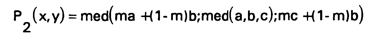
- P 2 (x, y) is the value of the interpolated pixel and corresponds to the median value among three values: the results of two linear filters and a median filter from the values of pixels a, b and c.
- the two linear filters perform a temporal interpolation with weighting coefficients corresponding to the relative positions of the pixel to interpolate with respect to pixels a, b, c. Note that these are two filters pure time, i.e. using only one pixel in each frame entry. This avoids a loss of vertical resolution.
- the median filter also allows to keep the generated frame good spatial resolution. But it also helps to keep some homogeneity between the different interpolation mechanisms of the three frames.
- Fallback 2 (x, y)
- x, y corresponds to a linear filtering severely cutting the high spatial frequencies on the two frames concerned:
- Pixel values not defined in the frames will be interpolated in simply using a vertical spatial filter on the upper pixels and lower.
- the value P 2 (x, y) is equal to the value of the pixel compensated in motion but framed so as not to be able to deviate from the value of the fallback pixel by a value greater than the confidence divided by a corrective factor .
- Frame 3 is interpolated from frames 2/3 and 4 (ie frame 1 of the following cycle) and the vectors of the sub-blocks SB 3 ( i, j ). Only the interpolation coefficients and the parity aspects of the lines will change.
- FIG. 14 illustrates this filtering.
- the continuity of the interpolation is well ensured with the previous frame since the algorithm is modeled on the frame interpolation 2.
- the sub-block vectors have a time bias - due to the fact that they were calculated from the main blocks determined for the output frame previous- which makes the definition of this frame worse than that of the previous frame, especially in the case of rapidly evolving movements.
- the chrominance interpolation algorithms are therefore directly extrapolated from those of luminance interpolation, considering frames containing half as many pixels horizontally, and dividing therefore by two the horizontal component of the motion vectors.
- film mode is that of video sequences which are generated, not in 625/50/2 format, but in 625/25/1. These sequences are so in a progressive format at the input, which means that each image input contains 2 frames corresponding to the same instant.
- the main motion estimate (the phase of main blocks) must be between a 1 pair frame and a 2/3 frame odd and no longer between an odd 1 frame and a 2/3 even frame.
- the chronograms given in figure 15 illustrate this operating mode particular.
- the film mode can be processed without modifying the filters and motion estimation mechanisms: it will suffice to control, once the presence of film mode has been detected, the processing phase, the interpolation coefficients of the frame filter 2 as well as the vectors and weft trusts 3. The reduction in saccade thus obtained will therefore be little expensive to implement.
Landscapes
- Engineering & Computer Science (AREA)
- Multimedia (AREA)
- Signal Processing (AREA)
- Computer Graphics (AREA)
- Television Systems (AREA)
- Complex Calculations (AREA)
- Compression, Expansion, Code Conversion, And Decoders (AREA)
Description


deuxièmement une valeur de repli qui résulte d'un filtrage linéaire temporel et horizontal sur les pixels des lignes des trames d'entrée précédente et suivante de position identique à la ligne contenant le pixel à interpoler, un filtrage spatial vertical étant effectué le cas échéant sur les lignes non définies des trames d'entrée.


- la figure 1 est un diagramme représentant les trames d'entrée et de sortie du présent procédé par rapport à l'axe du temps,
- la figure 2 est un diagramme bloc d'un dispositif mettant en oeuvre le procédé conforme au présent exemple de réalisation,
- la figure 3 représente un chronogramme des trames à certains points du dispositif de la figure 2,
- la figure 4 représente une image comportant des structures périodiques, ainsi qu'un exemple de vecteurs de mouvement pouvant être générés pour une telle image,
- la figure 5 représente un histogramme des erreurs d'une ligne d'une matrice d'erreur liée à une composante verticale d'un vecteur de mouvement donnée et contenant la plus petite erreur de la matrice,
- la figure 6 illustre le procédé mis en oeuvre pour tenir compte de blocs périodiques dans la détermination du champ de vecteurs de mouvement d'une image,
- la figure 7 représente deux filtres passe-bas,
- la figure 8 représente les trames 1, 2 et 2/3 et la position d'un sous-bloc par rapport aux blocs principaux dont les vecteurs sont sélectionnés en tant que vecteurs candidats pour le sous-bloc,
- la figure 9 représente les trames 1, 2/3 et 3 et la position d'un bloc intermédiaire par rapport aux blocs principaux dont les vecteurs sont utilisés en tant que vecteurs candidats,
- la figure 10 (a) représente une fonction non linéaire utilisée par le procédé de réduction de bruit temporelle récursive,
- la figure 10 (b) est un diagramme bloc d'un filtre de réduction de bruit temporelle récursive,
- la figure 11 représente un filtre spatio-temporel de type médian utilisé pour l'interpolation de la trame 1,
- la figure 12 illustre un problème lié à la présence de structures périodiques dans l'image;
- la figure 13 donne deux exemples de mise en oeuvre du filtre spatio-temporel utilisé pour l'interpolation de la trame 2,
- la figure 14 donne deux exemples de mise en oeuvre du filtre spatio-temporel utilisé pour l'interpolation de la trame 3,
- la figure 15 représente un chronogramme des trames à certains points du dispositif de la figure 2 lors du mode film, et
- la figure 16 comprend trois schémas (a,b,c) de trames par rapport au temps illustrant respectivement le mode de fonctionnement normal pour des trames vidéo, le mode de fonctionnement normal pour des trames film et le mode de fonctionnement spécifique pour des trames film.


- pendant la période 1, on calcule les vecteurs correspondant aux blocs principaux, représentatifs du mouvement entre les trames 1 et 2/3,
- pendant la période 2, on calcule les vecteurs correspondant aux sous-blocs, représentatifs de façon plus précise du mouvement entre les trames 1 et 2/3, le calcul se faisant à l'aide des vecteurs déterminés pendant la période 1,
- pendant la période 3, on calcule les vecteurs correspondant aux sous-blocs, représentatifs du mouvement entre les trames 2/3 et 4. Dans ce dernier cas, le calcul se fait à partir de vecteurs de blocs intermédiaires, qui sont constitués de valeurs rafraíchies des vecteurs correspondant aux blocs principaux.


- les deux minima doivent être proches en valeur (C1),
- la différence entre eux et le maximum secondaire doit être significative par rapport au niveau de bruit courant (C2).
pour tout u∈[-16,-14,...,14,16] et pour tout v∈[-4,...,4]

- on considère les vecteurs des deux blocs principaux en début et fin de la structure périodique. Pour chacun, on extrait de la matrice Sum l'erreur correspondante. Le vecteur dont l'erreur est la plus petite sera retenu,
- si ce vecteur ne correspond pas à un minimum local de sa ligne de la matrice d'erreur Sum, on sélectionne le minimum de la matrice d'erreur et on retient le vecteur correspondant,
- enfin, pour obtenir un cohérence verticale entre les blocs périodiques adjacents, on teste si un des blocs immédiatement supérieurs à cette rangée de blocs périodiques est également périodique et dans ce cas, on retient son vecteur, à condition toutefois qu'il corresponde bien à un minimum dans la ligne de la matrice d'erreur.
Pour m = 1,2,3
Pour m= 1,2,3,4


- le vecteur du bloc principal correspondant,
- le vecteur déduit du vecteur du bloc principal ci-dessus en modifiant sa composante horizontale d'un pas de quantification dans le sens positif,
- le vecteur déduit du bloc principal ci-dessus en modifiant sa composante horizontale d'un pas de quantification dans le sens négatif,
- le vecteur du bloc principal le plus proche (au-dessus ou en-dessous) du bloc intermédiaire,
- le vecteur déduit du bloc principal ci-dessus en modifiant sa composante horizontale d'un pas de quantification dans le sens positif,
- le vecteur déduit du bloc principal ci-dessus en modifiant sa composante horizontale d'un pas de quantification dans le sens négatif.
Si jmod4 < 2 alors j'=-1 sinon j'=1


est noté a∨b et son reste amodb.
Si imod8 < 4 alors i' =-1 sinon i' = 1
Pour m = 1,2

Pour m = 1,2

- une réduction de bruit spatiale,
- une réduction de bruit temporelle compensée en mouvement.
| x11 | x12 | x13 |
| x21 | x22 | x23 |
| x31 | x32 | x33 |
- Mise en correspondance des pixels sur lesquels va porter la relation de récurrence.
- Application de la relation de récurrence.


x→NL(x)

s = Noiseest
- on tentera de garder une homogénéité dans les différentes procédures d'interpolation adaptées à chaque trame: une différence trop brutale entre deux types d'interpolation conduit à des différences d'aspect d'une trame sur l'autre qui, répétées 75 fois par seconde, engendrent un scintillement plus gênant que celui que l'on cherche à réduire;
- on prendra les mesures nécessaires pour qu'une erreur sur un vecteur de mouvement, même importante en valeur mais suffisamment localisée, ou une différence entre le champ de vecteurs réel et celui mesuré due par exemple à la quantification, ne crée pas de perturbation trop visible. De plus, la présence de bruit dans l'image ne doit pas mettre en échec le procédé d'interpolation.
- interpolation linéaire verticale par moyennage (filtrage spatial pur)
- entrelacement des trames 1 et 2/3 dans les zones immobiles (filtrage temporel pur).
- interpolation mettant en oeuvre les vecteurs de mouvement (filtrage spatio-temporel)

pour y pair:

- dans un premier temps, on détermine trois valeurs correspondant à
trois filtres F1, F2 et F3,
- F1 réalise une moyenne des valeurs du pixel (b1) situé au dessus du pixel à interpoler et du pixel (b2) situé en dessous du pixel à interpoler,
- F2 donne la valeur médiane entre b1, b2 et la valeur du pixel (b) de la trame 2/3 correspondant à la translation par le vecteur de mouvement approprié du pixel à interpoler de la trame 1,
- F3 donne la valeur médiane parmi la valeur du pixel b et des valeurs des quatre pixels diagonalement adjacents (a1, c1, a2, c2) au pixel à interpoler,
- dans un second temps, on détermine la valeur médiane parmi les trois valeurs données par ces filtres.
Soient:


Pour y pair:


Pour y impair, soient


y pair:


Soient:


- une trame 1 progressive en utilisant le champ de vecteurs de blocs principaux, en conservant les lignes d'entrée et en interpolant les autres avec le filtre médian spatio-temporel à 7 points décrit précédemment,
- une trame 2 progressive en utilisant le champ de vecteurs de sous-blocs estimé avec les trames 1 et 2/3 d'entrée. On utilisera ici aussi le filtre médian temporel à 3 points décrit précédemment. Par contre au lieu d'appliquer les coefficients de pondération 2/3 et 1/3 ordinaires, on utilisera les coefficients 1/2 et 1/2; ce qui veut dire que la trame 2 que l'on génère ainsi est située à égale distance entre les trames d'entrées 1 et 2/3. Cette simple modification des coefficients constitue à elle seule une importante réduction de saccade, bien appréciable et sensible sur toutes les images qui ont été traitées. Voir figure 16 le schéma explicatif de cette réduction de saccade.
- et enfin une trame 3 progressive utilisant normalement le champ de vecteur des sous-blocs corrigé par les blocs intermédiaires. En fait, ici, puisque les trames 2/3 et 4 sont issues de la même image, il n'y a pas de mouvement entre ces deux trames. Il suffit donc de forcer les vecteur à zéro ainsi que la confiance: de cette façon le filtre décrit précédemment entrelacera purement et simplement les 2 trames d'entrée pour régénérer une image progressive parfaite.
Claims (15)
- Procédé de conversion de trames entrelacées en des trames progressives comprenant un changement de fréquences de trames par interpolation et compensation de mouvement caractérisé en ce quelorsque le vecteur de mouvement associé à un pixel à interpoler est non nul ou lorsque ce vecteur est nul, mais que la confiance accordée à ce vecteur est inférieure à un seuil donné,l'interpolation d'un pixel (x,y) d'une trame temporellement située entre deux trames d'entrée est réalisée par un filtrage médian portant sur les valeurs obtenues par un premier filtre temporel linéaire compensé en mouvement, un second filtre temporel linéaire compensé en mouvement et un filtre temporel médian compensé en mouvement.
- Procédé selon la revendication 1, caractérisé en ce que la confiance accordée à un vecteur est une fonction linéaire de l'erreur engendrée par ce vecteur.
- Procédé selon l'une des revendications 1 ou 2, caractérisé en ce que lesdits filtres linéaires sont fonction de deux pixels (a,b respectivement b,c) situés respectivement dans les trames d'entrée entourant temporellement la trame à interpoler, les coefficients linéaires d'interpolation de chaque pixel correspondant au rapport des intervalles de temps séparant la trame à interpoler et respectivement la trame d'entrée précédente et la trame d'entrée suivante.
- Procédé selon l'une des revendications 1 à 3, caractérisé en ce que lorsque la trame d'entrée précédente est impaire, ledit filtre temporel médian porte sur les trois pixels suivants:où Front(i,j) et Rear(i,j) sont les fractions du vecteur de mouvement associé au pixel à interpoler, ce vecteur étant mis à l'échelle et arrondi, où "0" et "1/2" représentent respectivement la trame d'entrée précédant respectivement suivant la trame à interpoler, et où m représente un coefficient d'interpolation dépendant de la position de la trame à interpoler entre les trames d'entrée.pour les lignes paires de la trame à interpoler

 alors:
 pour les lignes impaires de la trame à interpoler,
 alors:

- Procédé selon l'une des revendications 1 à 3, caractérisé en ce que lorsque la trame d'entrée précédente est impaire, ledit filtre temporel médian porte sur les trois pixels suivants:où Front(i,j) et Rear(i,j) sont les fractions du vecteur de mouvement associé au pixel à interpoler, ce vecteur étant mis à l'échelle et arrondi, où "1/2" et "1" représentent respectivement la trame d'entrée précédant respectivement suivant la trame à interpoler, et où n représente un coefficient d'interpolation dépendant de la position de la trame à interpoler entre les trames d'entrée.Pour les lignes impaires de la trame à interpoler:

 alors:
 Pour les lignes paires de la trame à interpoler
 alors:

- Procédé selon la revendication 3 et l'une des revendications 4 ou 5, caractérisé en ce que les deux pixels utilisés pour chaque filtre linéaire sont choisis dans le groupe de trois pixels utilisé par le filtre temporel médian.
- Procédé selon l'une des revendications précédentes, caractérisé en ce queles trames entrelacées d'entrée sont issues d'images progressives d'entrée de fréquence 25 Hz et que la fréquence des trames de sortie est de 75 Hz, une première trame de sortie (F1) étant temporellement confondue avec la seconde trame issue d'une première image d'entrée, une seconde trame de sortie (F2) étant temporellement située entre ladite première trame d'entrée et la première trame (F2/3) issue d'une seconde image d'entrée, une troisième trame de sortie (F3) étant temporellement située entre les deux trames d'entrée (F2/3, F4) issues de ladite seconde image d'entrée,les coefficients d'interpolation utilisés par lesdits filtres temporels sont de 1/2 pour ladite seconde trame de sortie.
- Procédé selon la revendication 7, caractérisé en ce que
les pixels de ladite troisième trame de sortie sont les pixels de la seconde image d'entrée. - Procédé selon l'une des revendications 1 à 8, caractérisé en ce quelorsque le vecteur de mouvement associé à un pixel à interpoler est nul et que la confiance dans ce vecteur dépasse un seuil donné, alors la valeur du pixel à interpoler est la valeur finale obtenue par filtrage médian entrepremièrement les deux valeurs de pixels obtenues en retirant, respectivement ajoutant la confiance du vecteur de mouvement ramenée au pixel divisée par un facteur correctif (Scale) à la valeur du pixel de même position que le pixel à interpoler dans, selon le cas, la trame d'entrée précédente ou la trame d'entrée suivante, etdeuxièmement une valeur de repli qui résulte d'un filtrage linéaire temporel et horizontal sur les pixels des lignes des trames d'entrée précédente et suivante de position identique à la ligne contenant le pixel à interpoler, un filtrage spatial vertical étant effectué le cas échéant sur les lignes non définies des trames d'entrée.
- Procédé selon la revendication 9, caractérisé en ce que la valeur de repli est égale à:où "0" désigne la trame d'entrée précédant la trame à interpoler et "1/2" la trame d'entrée suivant la trame à interpoler, et où m représente un coefficient de pondération dépendant de la position temporelle de la trame à interpoler entre les trames d'entrée.

- Procédé selon l'une des revendications 9 ou 10, caractérisé en ce quel'interpolation d'un pixel (P(x,y)) d'une ligne de parité donnée d'une trame (1) dont les lignes de parité opposée sont égales aux lignes d'une trame d'entrée (1) est réalisée, lorsque le vecteur de mouvement associé n'est pas nul ou que la confiance accordée à ce vecteur est faible, moyennant un filtrage médian (P1(x,y)) portant sur les valeurs obtenuespremièrement par un filtrage linéaire vertical (F1),deuxièmement par un filtrage médian spatio-temporel vertical sur deux pixels et compensé en mouvement sur un pixel (F2) ettroisièmement par un filtrage médian spatio-temporel portant sur quatre pixels en croix et compensé en mouvement sur un pixel (F3).
- Procédé selon la revendication 11, caractérisé en ce que ledit filtrage linéaire vertical (F1) est le suivant:où "0" représente la position temporelle de la trame à interpoler.

- Procédé selon l'une des revendications 11 ou 12, caractérisé en ce que ledit filtrage spatio-temporel vertical sur deux pixels et compensé en mouvement sur un pixel (F2) est:où Vx et Vy sont les coordonnées d'un vecteur de mouvement associé au pixel à interpoler, et où "0" représente la trame à interpoler et "1/2" la trame d'entrée suivante.

- Procédé selon l'une des revendications 11 à 13, caractérisé en ce que ledit filtrage spatio-temporel portant sur quatre pixels en croix et sur un pixel compensé en mouvement (F3) est:

- Procédé selon l'une des revendications 11 à 14, caractérisé en ce que lorsque le vecteur de mouvement associé à un pixel à interpoler est nul et que la confiance dans ce vecteur est supérieure à un seuil donné, alors ledit pixel prend la valeur du pixel de même position dans la trame d'entrée suivante.
Applications Claiming Priority (2)
| Application Number | Priority Date | Filing Date | Title |
|---|---|---|---|
| FR9515404 | 1995-12-22 | ||
| FR9515404A FR2742900B1 (fr) | 1995-12-22 | 1995-12-22 | Procede d'interpolation de trames progressives |
Publications (2)
| Publication Number | Publication Date |
|---|---|
| EP0781041A1 EP0781041A1 (fr) | 1997-06-25 |
| EP0781041B1 true EP0781041B1 (fr) | 2000-07-26 |
Family
ID=9485891
Family Applications (1)
| Application Number | Title | Priority Date | Filing Date |
|---|---|---|---|
| EP96402779A Expired - Lifetime EP0781041B1 (fr) | 1995-12-22 | 1996-12-18 | Procédé d'interpolation de trames progressives |
Country Status (6)
| Country | Link |
|---|---|
| US (1) | US5995154A (fr) |
| EP (1) | EP0781041B1 (fr) |
| JP (1) | JPH09261600A (fr) |
| CN (1) | CN1138422C (fr) |
| DE (1) | DE69609482T2 (fr) |
| FR (1) | FR2742900B1 (fr) |
Cited By (2)
| Publication number | Priority date | Publication date | Assignee | Title |
|---|---|---|---|---|
| US6904093B1 (en) | 1998-06-29 | 2005-06-07 | Samsung Electronics Co., Ltd. | Horizontal/vertical scanning frequency converting apparatus in MPEG decoding block |
| CN101968953A (zh) * | 2006-10-27 | 2011-02-09 | 夏普株式会社 | 图像显示装置及方法、图像处理装置及方法 |
Families Citing this family (94)
| Publication number | Priority date | Publication date | Assignee | Title |
|---|---|---|---|---|
| FR2750558B1 (fr) * | 1996-06-28 | 1998-08-28 | Thomson Multimedia Sa | Procede d'interpolation de trames pour compatibilite mode film |
| US6269484B1 (en) * | 1997-06-24 | 2001-07-31 | Ati Technologies | Method and apparatus for de-interlacing interlaced content using motion vectors in compressed video streams |
| FR2766946B1 (fr) | 1997-08-04 | 2000-08-11 | Thomson Multimedia Sa | Procede et dispositif de pretraitement pour estimation de mouvement |
| US6133957A (en) * | 1997-10-14 | 2000-10-17 | Faroudja Laboratories, Inc. | Adaptive diagonal interpolation for image resolution enhancement |
| US6122017A (en) * | 1998-01-22 | 2000-09-19 | Hewlett-Packard Company | Method for providing motion-compensated multi-field enhancement of still images from video |
| JP3734362B2 (ja) * | 1998-03-09 | 2006-01-11 | パイオニア株式会社 | 補間方法 |
| US6192079B1 (en) * | 1998-05-07 | 2001-02-20 | Intel Corporation | Method and apparatus for increasing video frame rate |
| KR100275700B1 (ko) * | 1998-07-10 | 2000-12-15 | 윤종용 | 영상신호 규격 변환장치 |
| US6297847B1 (en) * | 1998-08-03 | 2001-10-02 | S3 Graphics Co., Ltd. | Removal of interpolation artifacts in a non-interlaced video stream |
| US6239842B1 (en) * | 1998-12-18 | 2001-05-29 | Oplus Technologies Ltd. | Method of de-interlacing video signals using a mixed mode spatial and temporal approximation technique |
| US6594313B1 (en) * | 1998-12-23 | 2003-07-15 | Intel Corporation | Increased video playback framerate in low bit-rate video applications |
| US6496608B1 (en) * | 1999-01-15 | 2002-12-17 | Picsurf, Inc. | Image data interpolation system and method |
| JP2001014454A (ja) * | 1999-06-29 | 2001-01-19 | Sharp Corp | 画像処理装置 |
| US6735338B1 (en) | 1999-06-30 | 2004-05-11 | Realnetworks, Inc. | System and method for generating video frames and detecting text |
| US6731818B1 (en) | 1999-06-30 | 2004-05-04 | Realnetworks, Inc. | System and method for generating video frames |
| US6753865B1 (en) | 1999-06-30 | 2004-06-22 | Realnetworks, Inc. | System and method for generating video frames and post filtering |
| US6760378B1 (en) | 1999-06-30 | 2004-07-06 | Realnetworks, Inc. | System and method for generating video frames and correcting motion |
| WO2001035636A1 (fr) * | 1999-11-11 | 2001-05-17 | Stmicroelectronics Asia Pacific Pte Ltd. | Systeme de reduction spatio-temporelle du bruit video |
| FR2809267B1 (fr) * | 2000-05-19 | 2002-09-27 | Thomson Multimedia Sa | Procede de detection de saturation d'un champ de vecteurs mouvement |
| US6414719B1 (en) * | 2000-05-26 | 2002-07-02 | Sarnoff Corporation | Motion adaptive median filter for interlace to progressive scan conversion |
| KR100364762B1 (ko) * | 2000-06-22 | 2002-12-16 | 엘지전자 주식회사 | 순차주사 영상 변환 장치 및 방법과, 그를 이용한 수직주사율 변환 장치 |
| DE10033420A1 (de) * | 2000-07-08 | 2002-01-17 | Philips Corp Intellectual Pty | Vorrichtung zur Reduktion von Flackerstörungen |
| US20020039138A1 (en) * | 2000-09-29 | 2002-04-04 | Edelson Steven D. | Method and apparatus for automatically adjusting video panning and zoom rates |
| US7116372B2 (en) * | 2000-10-20 | 2006-10-03 | Matsushita Electric Industrial Co., Ltd. | Method and apparatus for deinterlacing |
| US7072392B2 (en) * | 2000-11-13 | 2006-07-04 | Micronas Semiconductors, Inc. | Equalizer for time domain signal processing |
| CN1235409C (zh) * | 2000-11-22 | 2006-01-04 | 皇家菲利浦电子有限公司 | 压缩编码视频的解压缩 |
| US6765964B1 (en) | 2000-12-06 | 2004-07-20 | Realnetworks, Inc. | System and method for intracoding video data |
| US6847406B2 (en) * | 2000-12-06 | 2005-01-25 | Koninklijke Philips Electronics N.V. | High quality, cost-effective film-to-video converter for high definition television |
| US6810081B2 (en) * | 2000-12-15 | 2004-10-26 | Koninklijke Philips Electronics N.V. | Method for improving accuracy of block based motion compensation |
| DE60127866T2 (de) * | 2001-01-16 | 2007-12-20 | Koninklijke Philips Electronics N.V. | Verringern von aura-artigen effekten bei der bewegungskompensierten interpolation |
| US6940557B2 (en) * | 2001-02-08 | 2005-09-06 | Micronas Semiconductors, Inc. | Adaptive interlace-to-progressive scan conversion algorithm |
| US6829297B2 (en) * | 2001-06-06 | 2004-12-07 | Micronas Semiconductors, Inc. | Adaptive equalizer having a variable step size influenced by output from a trellis decoder |
| US7190744B2 (en) * | 2001-06-07 | 2007-03-13 | Micronas Semiconductors, Inc. | Error generation for adaptive equalizer |
| US7418034B2 (en) * | 2001-06-19 | 2008-08-26 | Micronas Semiconductors. Inc. | Combined trellis decoder and decision feedback equalizer |
| US6992725B2 (en) * | 2001-10-22 | 2006-01-31 | Nec Electronics America, Inc. | Video data de-interlacing using perceptually-tuned interpolation scheme |
| KR100412501B1 (ko) * | 2001-11-30 | 2003-12-31 | 삼성전자주식회사 | 움직임 보상을 위한 화소값 선택 장치 및 방법 |
| US20030103567A1 (en) * | 2001-12-03 | 2003-06-05 | Riemens Abraham Karel | Motion compensation and/or estimation |
| CN100358356C (zh) * | 2002-02-28 | 2007-12-26 | 皇家飞利浦电子股份有限公司 | 用于场速率上变换的方法和装置 |
| US20030235259A1 (en) * | 2002-04-04 | 2003-12-25 | Jingsong Xia | System and method for symbol clock recovery |
| US20030206053A1 (en) * | 2002-04-04 | 2003-11-06 | Jingsong Xia | Carrier recovery for DTV receivers |
| US7272203B2 (en) * | 2002-04-05 | 2007-09-18 | Micronas Semiconductors, Inc. | Data-directed frequency-and-phase lock loop for decoding an offset-QAM modulated signal having a pilot |
| US7376181B2 (en) * | 2002-04-05 | 2008-05-20 | Micronas Semiconductors, Inc. | Transposed structure for a decision feedback equalizer combined with a trellis decoder |
| US7321642B2 (en) * | 2002-04-05 | 2008-01-22 | Micronas Semiconductors, Inc. | Synchronization symbol re-insertion for a decision feedback equalizer combined with a trellis decoder |
| US6995617B2 (en) * | 2002-04-05 | 2006-02-07 | Micronas Semiconductors, Inc. | Data-directed frequency-and-phase lock loop |
| US6980059B2 (en) * | 2002-04-05 | 2005-12-27 | Micronas Semiconductors, Inc. | Data directed frequency acquisition loop that synchronizes to a received signal by using the redundancy of the data in the frequency domain |
| US6975359B2 (en) * | 2002-04-25 | 2005-12-13 | Trident Microsystems, Inc. | Method and system for motion and edge-adaptive signal frame rate up-conversion |
| KR100854091B1 (ko) * | 2002-07-13 | 2008-08-25 | 삼성전자주식회사 | 영상신호의 필름 모드 검출장치 및 방법 |
| JP4198550B2 (ja) * | 2002-09-10 | 2008-12-17 | 株式会社東芝 | フレーム補間方法およびこのフレーム補間方法を用いた装置 |
| KR100927143B1 (ko) | 2002-11-27 | 2009-11-18 | 삼성전자주식회사 | 움직임 검출장치 및 방법 |
| KR20040054032A (ko) * | 2002-12-16 | 2004-06-25 | 삼성전자주식회사 | 영상신호의 포맷 검출장치 및 방법 |
| KR20040055059A (ko) * | 2002-12-20 | 2004-06-26 | 삼성전자주식회사 | 영상포맷의 변환장치 및 방법 |
| KR20040061244A (ko) * | 2002-12-30 | 2004-07-07 | 삼성전자주식회사 | 디-인터레이싱 방법 및 그 장치 |
| KR100530223B1 (ko) * | 2003-05-13 | 2005-11-22 | 삼성전자주식회사 | 프레임 레이트 변환시의 프레임 보간 방법 및 그 장치 |
| JP4003713B2 (ja) * | 2003-08-06 | 2007-11-07 | ソニー株式会社 | 画像処理装置および画像処理方法 |
| CN1846444B (zh) * | 2003-09-17 | 2011-01-26 | 汤姆森许可贸易公司 | 自适应参考画面产生 |
| GB2411784B (en) * | 2004-03-02 | 2006-05-10 | Imagination Tech Ltd | Motion compensation deinterlacer protection |
| CN103826133B (zh) * | 2004-05-04 | 2017-11-24 | 高通股份有限公司 | 运动补偿帧速率上调方法和设备 |
| KR100913260B1 (ko) * | 2004-07-01 | 2009-08-21 | 콸콤 인코포레이티드 | 규모 가변적 비디오 코딩에서 프레임 레이트 업 변환을 이용하는 방법 및 장치 |
| KR20070044455A (ko) | 2004-07-20 | 2007-04-27 | 콸콤 인코포레이티드 | 비디오 압축에 대한 인코더 보조-프레임 레이트 업컨버젼(ea-fruc)을 위한 방법 및 장치 |
| US8553776B2 (en) * | 2004-07-21 | 2013-10-08 | QUALCOMM Inorporated | Method and apparatus for motion vector assignment |
| TWI280798B (en) * | 2004-09-22 | 2007-05-01 | Via Tech Inc | Apparatus and method of adaptive de-interlace of image |
| JP4359223B2 (ja) * | 2004-10-29 | 2009-11-04 | 株式会社 日立ディスプレイズ | 映像補間装置とこれを用いたフレームレート変換装置,映像表示装置 |
| GB0427689D0 (en) * | 2004-12-15 | 2005-01-19 | Univ City | Reduced bandwidth flicker-free displays |
| US9225994B2 (en) * | 2005-03-14 | 2015-12-29 | British Telecommunications Public Limited Company | Global motion estimation using reduced frame lines |
| US7567294B2 (en) * | 2005-03-28 | 2009-07-28 | Intel Corporation | Gradient adaptive video de-interlacing |
| US8588513B2 (en) * | 2005-07-18 | 2013-11-19 | Broadcom Corporation | Method and system for motion compensation |
| US7538824B1 (en) * | 2005-08-18 | 2009-05-26 | Magnum Semiconductor, Inc. | Systems and methods for reducing noise during video deinterlacing |
| US20070230564A1 (en) * | 2006-03-29 | 2007-10-04 | Qualcomm Incorporated | Video processing with scalability |
| US8634463B2 (en) * | 2006-04-04 | 2014-01-21 | Qualcomm Incorporated | Apparatus and method of enhanced frame interpolation in video compression |
| US8750387B2 (en) * | 2006-04-04 | 2014-06-10 | Qualcomm Incorporated | Adaptive encoder-assisted frame rate up conversion |
| US8055102B1 (en) | 2006-11-08 | 2011-11-08 | Marvell International Ltd. | Local edge count heuristic for vector interpolator |
| US8300987B2 (en) * | 2007-09-28 | 2012-10-30 | Ati Technologies Ulc | Apparatus and method for generating a detail-enhanced upscaled image |
| US8964117B2 (en) | 2007-09-28 | 2015-02-24 | Ati Technologies Ulc | Single-pass motion adaptive deinterlacer and method therefore |
| US8259228B2 (en) * | 2007-12-10 | 2012-09-04 | Ati Technologies Ulc | Method and apparatus for high quality video motion adaptive edge-directional deinterlacing |
| US20090153739A1 (en) * | 2007-12-14 | 2009-06-18 | Texas Instruments Incorporated | Method and Apparatus for a Noise Filter for Reducing Noise in a Image or Video |
| US8396129B2 (en) * | 2007-12-28 | 2013-03-12 | Ati Technologies Ulc | Apparatus and method for single-pass, gradient-based motion compensated image rate conversion |
| CN101521738B (zh) * | 2008-02-26 | 2011-09-28 | 瑞昱半导体股份有限公司 | 图像画面的差补方法及其图像处理装置 |
| US11677938B2 (en) * | 2008-04-30 | 2023-06-13 | Arris Enterprises Llc | Method to reduce contour artifacts on recursive temporal filters |
| US20100092101A1 (en) * | 2008-10-09 | 2010-04-15 | Chin-Chuan Liang | Methods and apparatus for enhancing image quality of motion compensated interpolation |
| JP2010093680A (ja) * | 2008-10-10 | 2010-04-22 | Victor Co Of Japan Ltd | 映像信号処理装置及び映像信号処理方法 |
| US8059198B2 (en) * | 2009-01-12 | 2011-11-15 | Himax Technologies Limited | Apparatus and method for motion adaptive de-interlacing with chroma up-sampling error remover |
| US9654792B2 (en) | 2009-07-03 | 2017-05-16 | Intel Corporation | Methods and systems for motion vector derivation at a video decoder |
| US8471959B1 (en) * | 2009-09-17 | 2013-06-25 | Pixelworks, Inc. | Multi-channel video frame interpolation |
| CN101699856B (zh) * | 2009-10-30 | 2012-01-18 | 北京中科大洋科技发展股份有限公司 | 一种运动自适应的去交织方法 |
| US9215353B2 (en) * | 2010-06-08 | 2015-12-15 | Sharp Kabushiki Kaisha | Image processing device, image processing method, image display device, and image display method |
| US8861894B2 (en) | 2011-05-27 | 2014-10-14 | Adobe Systems Incorporated | Methods and apparatus for edge-aware pixel data generation |
| JP6037224B2 (ja) * | 2012-01-11 | 2016-12-07 | パナソニックIpマネジメント株式会社 | 画像処理装置、撮像装置、およびプログラム |
| CN102665060B (zh) * | 2012-04-25 | 2013-07-24 | 中国科学技术大学 | 从交错式格式视频到渐进式格式视频的转换方法 |
| US20140092992A1 (en) | 2012-09-30 | 2014-04-03 | Microsoft Corporation | Supplemental enhancement information including confidence level and mixed content information |
| KR101394468B1 (ko) * | 2013-11-12 | 2014-05-14 | 주식회사 아나패스 | 블록의 불연속도 연산방법 및 이를 이용한 폴백 수행 방법 |
| CN110447052B (zh) * | 2017-04-05 | 2023-03-14 | 奥林巴斯株式会社 | 相关值运算装置 |
| CN109426786A (zh) * | 2017-08-31 | 2019-03-05 | 爱唯秀股份有限公司 | 人数检测系统与人数检测方法 |
| US10382718B2 (en) * | 2017-12-27 | 2019-08-13 | Anapass Inc. | Frame rate detection method and frame rate conversion method |
| CN112770125A (zh) * | 2020-12-23 | 2021-05-07 | 深圳市尊正数字视频有限公司 | 直播视频低延迟显示的方法、系统及电子设备 |
Family Cites Families (14)
| Publication number | Priority date | Publication date | Assignee | Title |
|---|---|---|---|---|
| DE3114613A1 (de) | 1981-04-10 | 1982-11-04 | Folienwalzwerk Brüder Teich AG, Obergrafendorf | Verschlusskappe fuer behaelter |
| FR2604049B1 (fr) * | 1986-09-12 | 1988-11-10 | Labo Electronique Physique | Procede de conversion de signaux video entrelaces en signaux video non entrelaces et convertisseur de signaux video pour la mise en oeuvre de ce procede |
| GB2231745B (en) * | 1989-04-27 | 1993-07-07 | Sony Corp | Motion dependent video signal processing |
| GB2246488B (en) * | 1990-07-24 | 1994-04-20 | Sony Corp | Motion dependant video signal processing |
| DE4211955A1 (de) * | 1992-04-09 | 1993-10-14 | Thomson Brandt Gmbh | Verfahren und Vorrichtung für eine interlace-progressiv-Wandlung |
| DE69315626T2 (de) * | 1992-05-15 | 1998-05-28 | Koninkl Philips Electronics Nv | Anordnung zum Interpolieren eines bewegungsausgeglichenen Bildsignals |
| DE69323572T2 (de) * | 1992-06-11 | 1999-09-16 | Koninkl Philips Electronics Nv | Anordnung zum bewegungsausgeglichenen Interpolieren eines Bildsignals |
| GB9214218D0 (en) * | 1992-07-03 | 1992-08-12 | Snell & Wilcox Ltd | Motion compensated video processing |
| ES2118173T3 (es) * | 1992-11-19 | 1998-09-16 | Thomson Multimedia Sa | Metodo y aparato para conversion ascendente de frecuencia de campo. |
| FR2700090B1 (fr) * | 1992-12-30 | 1995-01-27 | Thomson Csf | Procédé de désentrelacement de trames d'une séquence d'images animées. |
| KR970009469B1 (ko) * | 1993-06-05 | 1997-06-13 | 삼성전자 주식회사 | 더블스무딩(Double Smoothing) 기능을 갖는 비월/순차주사변환장치 및 그 방법 |
| IT1261633B (it) * | 1993-10-26 | 1996-05-23 | Seleco Spa | Metodo per la conversione della frequenza di ripetizione delle trame di un segnale video da 50 hz a 75 hz con compensazione del movimento eapparecchiatura per la implementazione di tale metodo. |
| US5519451A (en) * | 1994-04-14 | 1996-05-21 | Texas Instruments Incorporated | Motion adaptive scan-rate conversion using directional edge interpolation |
| US5631706A (en) * | 1995-06-07 | 1997-05-20 | Mitsubishi Consumer Electronics America, Inc. | Converter and method for converting video signals of interlace format to video signals of progressive format |
-
1995
- 1995-12-22 FR FR9515404A patent/FR2742900B1/fr not_active Expired - Fee Related
-
1996
- 1996-12-10 US US08/763,178 patent/US5995154A/en not_active Expired - Fee Related
- 1996-12-18 DE DE69609482T patent/DE69609482T2/de not_active Expired - Fee Related
- 1996-12-18 EP EP96402779A patent/EP0781041B1/fr not_active Expired - Lifetime
- 1996-12-20 JP JP8342170A patent/JPH09261600A/ja active Pending
- 1996-12-22 CN CNB961238453A patent/CN1138422C/zh not_active Expired - Fee Related
Cited By (3)
| Publication number | Priority date | Publication date | Assignee | Title |
|---|---|---|---|---|
| US6904093B1 (en) | 1998-06-29 | 2005-06-07 | Samsung Electronics Co., Ltd. | Horizontal/vertical scanning frequency converting apparatus in MPEG decoding block |
| CN101968953A (zh) * | 2006-10-27 | 2011-02-09 | 夏普株式会社 | 图像显示装置及方法、图像处理装置及方法 |
| CN101968953B (zh) * | 2006-10-27 | 2012-11-28 | 夏普株式会社 | 图像显示装置及方法、图像处理装置及方法 |
Also Published As
| Publication number | Publication date |
|---|---|
| CN1170317A (zh) | 1998-01-14 |
| EP0781041A1 (fr) | 1997-06-25 |
| FR2742900B1 (fr) | 1998-02-13 |
| DE69609482D1 (de) | 2000-08-31 |
| US5995154A (en) | 1999-11-30 |
| CN1138422C (zh) | 2004-02-11 |
| JPH09261600A (ja) | 1997-10-03 |
| FR2742900A1 (fr) | 1997-06-27 |
| DE69609482T2 (de) | 2001-03-29 |
Similar Documents
| Publication | Publication Date | Title |
|---|---|---|
| EP0781041B1 (fr) | Procédé d'interpolation de trames progressives | |
| EP0780794B1 (fr) | Procédé de correction d'estimation de mouvement dans des images à structures périodiques | |
| EP0316231B1 (fr) | Procédé et dispositif de traitement de signaux d'image à balayage de trame entrelacé | |
| EP0677228B1 (fr) | Procede de desentrelacement de trames d'une sequence d'images animees | |
| EP0330279B1 (fr) | Dispositif de sous-échantillonnage spatio-temporel de signaux vidéo numériques représentatifs d'une suite d'images entrelacées ou séquentielles, système de transmission d'images de télévision à haute définition incluant un tel dispositif, et étages d'émission et de réception pour un tel système | |
| EP0347984A1 (fr) | Système de traitement d'images de télévision à estimateur de vitesses amélioré et à débit de données réduit | |
| Van Roosmalen et al. | Correction of intensity flicker in old film sequences | |
| FR2958824A1 (fr) | Procede de traitement d'images stereoscopiques et dispositif correspondant | |
| EP3114831B1 (fr) | Débruitage vidéo optimisé pour système multicapteur hétérogène | |
| EP1908297A1 (fr) | Dispositif de generation d'une image interpolee | |
| FR2779852A1 (fr) | Appareil de multiplication de lignes video procurant une finesse de details amelioree, et procede associe | |
| FR2599204A1 (fr) | Processeur de signaux video a balayage progressif | |
| EP0337565B1 (fr) | Dispositif de codage de signaux représentatifs d'une suite d'images et système de transmission d'images de télévision à haute définition incluant un tel dispositif | |
| EP0780795A1 (fr) | Procédé d'estimation de mouvement | |
| EP0365090B1 (fr) | Dispositif de doublement du rythme de signaux de télévision, et décodeur d'images de télévision comprenant un tel dispositif | |
| EP0546141A1 (fr) | Procede de conversion du rythme temporel d'une sequence d'images animees | |
| WO1990000846A1 (fr) | Codage et decodage d'images de television a haute definition | |
| EP0391760B1 (fr) | Dispositif de conversion de fréquence trame pour un récepteur de télévision haute définition, et procédé de détection du mouvement dans une image de télévision codée | |
| Keller et al. | Temporal super resolution using variational methods | |
| FR2651405A1 (fr) | Procede et dispositif de traitement d'images a estimation de mouvement amelioree. | |
| FR2689354A1 (fr) | Procédé récursif de restauration d'une image vidéo dégradée. | |
| Kokaram et al. | Advances in automated restoration of archived video | |
| FR3124301A1 (fr) | Procédé de construction d’une image de profondeur d’une vidéo multi-vues, procédé de décodage d’un flux de données représentatif d’une vidéo multi-vues, procédé de codage, dispositifs, système, équipement terminal, signal et programmes d’ordinateur correspondants. | |
| Kosykh | Correction of the pulse response of the video registration system after accumulation of a series of mutually shifted images | |
| Roscoe | Enhancement of digitised analogue video recordings using multiple image processing algorithms |
Legal Events
| Date | Code | Title | Description |
|---|---|---|---|
| PUAI | Public reference made under article 153(3) epc to a published international application that has entered the european phase |
Free format text: ORIGINAL CODE: 0009012 |
|
| AK | Designated contracting states |
Kind code of ref document: A1 Designated state(s): DE FR GB IT |
|
| 17P | Request for examination filed |
Effective date: 19971208 |
|
| RAP1 | Party data changed (applicant data changed or rights of an application transferred) |
Owner name: THOMSON MULTIMEDIA |
|
| GRAG | Despatch of communication of intention to grant |
Free format text: ORIGINAL CODE: EPIDOS AGRA |
|
| 17Q | First examination report despatched |
Effective date: 19990927 |
|
| GRAG | Despatch of communication of intention to grant |
Free format text: ORIGINAL CODE: EPIDOS AGRA |
|
| GRAH | Despatch of communication of intention to grant a patent |
Free format text: ORIGINAL CODE: EPIDOS IGRA |
|
| GRAH | Despatch of communication of intention to grant a patent |
Free format text: ORIGINAL CODE: EPIDOS IGRA |
|
| GRAA | (expected) grant |
Free format text: ORIGINAL CODE: 0009210 |
|
| AK | Designated contracting states |
Kind code of ref document: B1 Designated state(s): DE FR GB IT |
|
| REF | Corresponds to: |
Ref document number: 69609482 Country of ref document: DE Date of ref document: 20000831 |
|
| ITF | It: translation for a ep patent filed |
Owner name: JACOBACCI & PERANI S.P.A. |
|
| GBT | Gb: translation of ep patent filed (gb section 77(6)(a)/1977) |
Effective date: 20001031 |
|
| PLBE | No opposition filed within time limit |
Free format text: ORIGINAL CODE: 0009261 |
|
| STAA | Information on the status of an ep patent application or granted ep patent |
Free format text: STATUS: NO OPPOSITION FILED WITHIN TIME LIMIT |
|
| 26N | No opposition filed | ||
| REG | Reference to a national code |
Ref country code: GB Ref legal event code: 746 Effective date: 20011123 |
|
| REG | Reference to a national code |
Ref country code: GB Ref legal event code: IF02 |
|
| REG | Reference to a national code |
Ref country code: FR Ref legal event code: D6 |
|
| PGFP | Annual fee paid to national office [announced via postgrant information from national office to epo] |
Ref country code: GB Payment date: 20071128 Year of fee payment: 12 Ref country code: FR Payment date: 20071218 Year of fee payment: 12 |
|
| PGFP | Annual fee paid to national office [announced via postgrant information from national office to epo] |
Ref country code: IT Payment date: 20071228 Year of fee payment: 12 Ref country code: DE Payment date: 20071219 Year of fee payment: 12 |
|
| GBPC | Gb: european patent ceased through non-payment of renewal fee |
Effective date: 20081218 |
|
| REG | Reference to a national code |
Ref country code: FR Ref legal event code: ST Effective date: 20090831 |
|
| PG25 | Lapsed in a contracting state [announced via postgrant information from national office to epo] |
Ref country code: DE Free format text: LAPSE BECAUSE OF NON-PAYMENT OF DUE FEES Effective date: 20090701 |
|
| PG25 | Lapsed in a contracting state [announced via postgrant information from national office to epo] |
Ref country code: GB Free format text: LAPSE BECAUSE OF NON-PAYMENT OF DUE FEES Effective date: 20081218 |
|
| PG25 | Lapsed in a contracting state [announced via postgrant information from national office to epo] |
Ref country code: FR Free format text: LAPSE BECAUSE OF NON-PAYMENT OF DUE FEES Effective date: 20081231 |
|
| PG25 | Lapsed in a contracting state [announced via postgrant information from national office to epo] |
Ref country code: IT Free format text: LAPSE BECAUSE OF NON-PAYMENT OF DUE FEES Effective date: 20081218 |