EP0780943A1 - Kabelentmantelungsmatrizen und Verfahren zu deren Verwendung - Google Patents
Kabelentmantelungsmatrizen und Verfahren zu deren Verwendung Download PDFInfo
- Publication number
- EP0780943A1 EP0780943A1 EP96118266A EP96118266A EP0780943A1 EP 0780943 A1 EP0780943 A1 EP 0780943A1 EP 96118266 A EP96118266 A EP 96118266A EP 96118266 A EP96118266 A EP 96118266A EP 0780943 A1 EP0780943 A1 EP 0780943A1
- Authority
- EP
- European Patent Office
- Prior art keywords
- cable
- die
- insulation
- dies
- cutting blades
- Prior art date
- Legal status (The legal status is an assumption and is not a legal conclusion. Google has not performed a legal analysis and makes no representation as to the accuracy of the status listed.)
- Withdrawn
Links
Images


Classifications
-
- H—ELECTRICITY
- H02—GENERATION; CONVERSION OR DISTRIBUTION OF ELECTRIC POWER
- H02G—INSTALLATION OF ELECTRIC CABLES OR LINES, OR OF COMBINED OPTICAL AND ELECTRIC CABLES OR LINES
- H02G1/00—Methods or apparatus specially adapted for installing, maintaining, repairing or dismantling electric cables or lines
- H02G1/12—Methods or apparatus specially adapted for installing, maintaining, repairing or dismantling electric cables or lines for removing insulation or armouring from cables, e.g. from the end thereof
- H02G1/1202—Methods or apparatus specially adapted for installing, maintaining, repairing or dismantling electric cables or lines for removing insulation or armouring from cables, e.g. from the end thereof by cutting and withdrawing insulation
- H02G1/1204—Hand-held tools
- H02G1/1229—Hand-held tools the cutting element making a longitudinal, and a transverse or a helical cut
Definitions
- This invention relates generally to cable stripping dies, and more particularly to hydraulically operated tools employing such dies to shear the insulation from electrical cables, such as aerial power lines, whether such cables are energized, or not.
- Tools for stripping insulation from electrical cables are well known and highly developed. The majority of such tools require that the tool move relative to the longitudinal axis of the insulated cable so that the insulation is scored in a helical manner. The depth of the scoring must be controlled, lest the conductive core of the electrical cable be nicked, which leads to deterioration of the cable. After the scoring operation has been completed, the insulation must be wedged free of the cable and then removed by a needle nosed plier or other manual tool.
- the tool includes a plurality of rollers (66, 76; 78, 80; 82, 84; and 86, 88) for supporting cables of different diameters, while permitting rotation of the tool relative to the cable.
- the tool includes a blade (92) which is positioned to cut into the insulation of the cable upon relative rotation thereto.
- the axis of rotation of each supporting roller is angled relative to the longitudinal axis (101) of the supported cable so that the cable and tool move relatively axially during such relative rotation thereof.
- Handles (112, 114) are used to rotate the tool, and the spirals of cut insulation are shown in dotted outline in FIG. 1 of Maytham '818.
- U.S. Patent 4,179,804 granted December 25, 1979 to Walter J. Maythem, and assigned to Speed Systems, Inc., also discloses a tool (10) for removing insulation (12) from the core, or conductor (16), of an electrical cable.
- a plurality of rollers (32) are provided, with the axis of rotation for each roller being adjusted relative to the longitudinal axis of the cable, at a selected angle (as shown in FIG. 3).
- a cutting blade (68) is adjustably mounted relative to the conductor.
- the tool is characterized further by a plurality of rollers (44, 46) which are adjustable together, so that the angle between the rotation of each such roller is varied relative to the longitudinal axis of the cable.
- Such tool is capable of determining, and varying, the axial thickness of cable insulation to be cut for each turn of the tool relative to the cable, as noted in column 1, lines 34-38 of Maytham '804. Also, the rate of feed can be chosen to be zero to allow a flat face of insulation to be cut on an end thereof, as noted in column 1, lines 29-31.
- the instant invention sets forth a unique set of cable stripping dies that function admirably in removing insulation from insulated electrical cables, including the tenacious semi-conductive layer.
- the unique dies cleanly remove the insulation by shearing same at the desired location, thereby exposing the conductive core of the cable.
- the insulation remaining on the cable is an arcuate "slug,” that can be removed manually so that a tap, splice, or other electrical connection, can readily be established with the exposed conductive core of the cable.
- the unique die set consists of two identical dies that are oppositely disposed in the jaws of the working head of a hydraulic tool.
- Cutting blades are secured to the opposite sides of each die body to pierce the insulation while centering the dies on the insulated electrical cable.
- the cutting blades engage, in an abutting manner, as the blades are drawn toward their closed position.
- Longitudinal knife edges on each die shear the insulation, and separate same from the metallic core of the electrical cable.
- the cutting blades and knife edges work in concert with each other.
- An arcuate "slug" of insulation remains loosely engaged with, or resting upon, the metallic core, and such slug is easily removed by hand, or with a manual tool.
- the instant stripping die set is admirably suited for use in known hydraulically operated crimping tools, such as the Burndy Y46 series of tools, available from the Burndy Corporation of Manchester, New Hampshire. These crimping tools may be utilized in conjunction with insulated "hot sticks", so that mid-span connections may be effectuated while overhead power lines are energized. The ability to work on power lines, while energized, without compromising worker safety, is highly desirable.
- crimping tools employing the instant dies are well suited for working in close quarters, since the tool need not be advanced, or rotated, relative to the longitudinal axis of the electrical cable to be stripped. Such capability makes the tool employing such dies well-suited for mid-span operations, and further adapts the crimping tool for use with cables having multiple layers of insulation, including a semi-conductive layer that is bonded to, or adhered to, the metallic core of the insulated cable.
- the objectives of the present invention are realized by the straight-line movement of the instant dies when installed in the jaws of a hydraulically operated crimping tool.
- a cutting blade with a semi-circular cut-out and tapered edges is situated at each side of the die, and a pair of longitudinally extending knife edges are located therebetween.
- the cutting blades abut, in the radial and circumferential directions, when the dies are forced together to pierce the outer layer of insulation.
- the knife edges shear segments of the insulation from opposite faces of the conductive core of the cable in a parallel fashion. Angled surfaces on the dies free the insulation from the metallic core of the cable, after such insulation has been cut by the knife edges.
- the method of stripping insulation from an electrical cable when utilizing the unique dies, is simplified considerably.
- the method entails the steps of (1) introducing the insulated cable between the opposing dies when mounted in a crimping head of a tool, (2) advancing the dies into engagement with the insulation on the cable so that the cutting blades center the dies on the cable, (3) continuing the straight-line advancement of the dies toward one another so that the longitudinally extending knife edges on each die shear the insulation on the cable and sever arcuate segments therefrom, to expose opposite faces of the core of the cable, and (4) removing the remaining "slugs" of insulation to completely expose the core of the cable.
- the method of operation functions optimally when the segments of insulation sheared by the cutting dies are parallel to each other. The remaining slugs of insulation may be removed manually, as with a gloved hand, or by a simple manual tool.
- the unique die set may be included as an integral part of new crimping tools, or existing crimping tools may be retrofitted with such die set.
- the die set may be fabricated in a variety of sizes, so that insulated cables, of different diameters, may be stripped efficiently, while the cables are energized. While the instant dies were developed for use on overhead power cables, the dies may be used with other power cables, with equal facility. Also, the instant dies do not nick the metallic core of insulated cables, and thus may be used whether the power lines are energized, or not, without endangering the linesperson utilizing the hydraulic tool.
- FIG. 1 depicts, in a schematic fashion, the environment in which the unique cable stripper dies function.
- a linesperson operates out of a bucket so that he/she can service the overhead, or aerial, power transmission cables 12.
- the linesperson is equipped with an insulated "hot stick" 14.
- a manual control 16 is located on one end of the "hot stick,” so that the linesperson can operate working head 18 situated at the remote end of the "hot stick.”
- the working head is C-shaped, in side elevation, to fit over an individual cable 12 and prepare same for taps, splices, terminations, and the like.
- FIG. 2 shows working head 18 in greater detail.
- the head is formed of a forged steel body 20, with a reinforced back 22.
- a fixed jaw 24 is located at the upper end of body 20, and a cooperating, movable jaw 26 is situated therebelow.
- a die lock 28 is located on jaw 24, and an identical die lock 30 is located on jaw 26. The dies retained in place by locks 28 and 30 are shown in phantom outline in FIG. 2.
- Hydraulic fitting 32 is located at the lower end of working head 18, and fitting 32 allows hydraulic pressure, which may reach 10,000 psi, to be introduced into the crimping head, from a remote source (not shown), to drive movable jaw 26 toward fixed jaw 24.
- Crimping head 18 and the hydraulic power source therefor are known, commercially available components, sold under the trademark "Y46 Series” by Burndy Corporation of Manchester, New Hampshire, the assignee of the instant application.
- FIGS. 3A and 3B show an upper die indicated generally by reference numeral 34, engaged with die lock 28 in jaw 24, while a lower die, indicated generally by reference numeral 36, is engaged with die lock 30 in jaw 26.
- the dies are identical in size and shape, but are mounted facing in opposite directions for cooperative interaction.
- FIG. 3A shows movable jaw 26 in its lowermost position
- FIG. 3B shows the same jaw at its uppermost, or closed position.
- FIG. 4 shows a fragment of insulated cable 12.
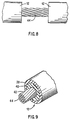
- Cable 12 includes an outer layer 38 of high density polyethylene, a central layer 40 of high molecular weight polyethylene, a smaller inner layer 42 of semi-conducting polyethylene, and a core 44 formed of wires made from a conductive metal, such as aluminum.
- a conductive metal such as aluminum.
- One representative cable of such configuration is manufactured and distributed by the Hendrix Wire and Cable Co. of Milford, New Hampshire.
- Upper die 34 comprises a first mounting plate 46 and a second mounting plate 48 secured to opposite lateral sides of die body 50.
- the mounting plates cooperate with die lock 28 to secure die 34 to fixed jaw 24.
- Mounting plate 46 is secured to the front face of the jaw, while mounting plate 48 is secured to the rear face (not shown) of the jaw.
- Die body 50 fits snugly within jaw 24.
- a first cutting blade 52 is secured to body 50 of upper die 34 below first mounting plate 46 by fasteners 54, and a second cutting blade 56 is secured to body 50 below second mounting plate 48 in a similar manner.
- Lower die 36 as shown in FIGS. 4 and 5, has a first mounting plate 58 and a second mounting plate 60 secured to opposite lateral sides of die body 62.
- the mounting plates cooperate with die lock 30 to secure die 36 to movable jaw 26.
- Mounting plates 58, 60 are secured to the opposite faces of jaw 26,and die body 62 fits snugly within the jaw.
- Die body 62 includes a base 64 that is arcuate in end-elevation, and an upwardly opening, U-shaped channel 66 that extends longitudinally through base 64.
- the upper edges of channel 66 are sharpened to form spaced knife edges 68, 70.
- the knife edges are parallel to one another.
- a first outwardly tapering surface 72 is formed outboard of knife edge 70, while a second outwardly tapering surface 74 is formed outboard of knife edge 68.
- a first cutting blade 76 is secured to one face of die body 62 adjacent to mounting plate 58, while a second cutting blade 78 is secured to the opposite face of the die body.
- Fasteners 54 assume the form of threaded bolts that pass through passages drilled longitudinally through the die body and apertures in the cutting blades, and secure the cutting blades 76, 78 to the die body, at opposite lateral sides thereof.
- Cutting blade 76 includes a rigid body of high-strength steel, with a centrally located semi-circular cut-out 80 and tapered surface 82 located on opposite sides thereof.
- Cutting blades 52, 56, 76 and 78 are identical in shape.
- Dies 34 and 36 are identical in shape, but are rotated 180° from one another, so that the channel, cutting edges, etc. in die 34 are not visible in FIG. 4.
- FIGS. 6 and 7 show the manner in which cutting blades 52, 76; 56, 78 abut, when movable jaw 26 is driven through the insulated cable to contact fixed jaw 24 of working head 18.
- the cutting blades including the tapered surfaces 80, 82, etc., cause the dies 34, 36, to penetrate the insulating layers on cable 12 and center the dies thereupon, during the initial phase of an insulation stripping operation. The penetration of the cutting blades continues until the segment of insulation between the blades is cut free from the metallic core 44 of the cable 12, but without scoring or nicking same.
- FIG. 7 shows that cutting blade 52 in upper die 34 contacts cutting blade 76 in lower die 36 at the completion of the power stroke forcing the dies together.
- the removal of the slugs of insulation in an expeditious fashion reveals 2-5 inches of core 44; a mid-span tap may then be completed in the usual manner.
- the insulation is removed cleanly and neatly, whether the cable is energized or not, and the minimum possible amount of insulation is removed, because of the straight-line operation of the hydraulic crimping tool and the configuration of the unique die set.
- dies 34, 36 can be employed within working head 18 to prepare cable 12 to receive a connector, a splice, an end termination, or the like.
- the stripper dies thus are capable of diverse functions, carried forth in a speedy and efficient manner, and without damaging power transmission cable 12 by nicking, or scoring, its metallic core.
- the cable stripping dies 34, 36 were developed to remove insulation, including the tenacious semi-conductive (semi-con) layer from power transmission cable, such as cable 12, the stripping dies function satisfactorily with other types of power cables, such as copper, ACSR, AWAC, NAVY, etc. Consequently, the cable stripping dies 34, 36 can be used with any cable that has at least one layer of insulation, or a jacket, that must be removed prior to making terminations, or mid-span taps, splices, or applying terminals, even while the cable is energized.
Landscapes
- Removal Of Insulation Or Armoring From Wires Or Cables (AREA)
Applications Claiming Priority (2)
| Application Number | Priority Date | Filing Date | Title |
|---|---|---|---|
| US57614095A | 1995-12-22 | 1995-12-22 | |
| US576140 | 1995-12-22 |
Publications (1)
| Publication Number | Publication Date |
|---|---|
| EP0780943A1 true EP0780943A1 (de) | 1997-06-25 |
Family
ID=24303137
Family Applications (1)
| Application Number | Title | Priority Date | Filing Date |
|---|---|---|---|
| EP96118266A Withdrawn EP0780943A1 (de) | 1995-12-22 | 1996-11-14 | Kabelentmantelungsmatrizen und Verfahren zu deren Verwendung |
Country Status (1)
| Country | Link |
|---|---|
| EP (1) | EP0780943A1 (de) |
Cited By (7)
| Publication number | Priority date | Publication date | Assignee | Title |
|---|---|---|---|---|
| US9393683B2 (en) | 2014-05-02 | 2016-07-19 | M. W. Bevins Co. | Conductive boot for power tool protection |
| US20170201055A1 (en) * | 2016-01-07 | 2017-07-13 | Hubbell Incorporated | Wire stripping die for crimping tool |
| CN113300287A (zh) * | 2021-06-22 | 2021-08-24 | 广东电网有限责任公司 | 一种剥线工具 |
| WO2023031395A1 (de) | 2021-09-03 | 2023-03-09 | Gustav Klauke Gmbh | Paar von werkzeugteilen, verfahren zur abisolierung eines kabels sowie verfahren zum vercrimpen eines presslings |
| DE102023102042A1 (de) | 2023-01-27 | 2024-08-01 | Gustav Klauke Gmbh | Abisolierwerkzeug, Paar von Werkzeugteilen für ein Abisolierwerkzeug sowie Verfahren zur Abisolierung eines Kabels |
| DE102023104915A1 (de) | 2023-02-28 | 2024-08-29 | Gustav Klauke Gmbh | Abisolierwerkzeug, Paar von Werkzeugteilen, Werkzeugelement sowie Verfahren zur Abisolierung eines Kabels |
| KR102920507B1 (ko) * | 2024-11-29 | 2026-01-30 | (주)유원이앤씨 | 간격조절 가능한 이중날을 구비한 전력선 활선 작업용 스마트 스틱 |
Citations (11)
| Publication number | Priority date | Publication date | Assignee | Title |
|---|---|---|---|---|
| US3237300A (en) * | 1963-03-25 | 1966-03-01 | Townsend Mary Dorothy | Insulation cutting pliers having parallel longitudinal and transverse cutting edges |
| US3599514A (en) * | 1969-10-15 | 1971-08-17 | Theodore A Fornkahl | Insulation removal tool |
| US3969818A (en) | 1975-10-08 | 1976-07-20 | Speed Systems, Inc. | Cable insulation stripping tool |
| US3978582A (en) | 1975-02-18 | 1976-09-07 | Speed Systems, Inc. | Cable insulation stripping tool |
| US3990331A (en) | 1975-03-31 | 1976-11-09 | Utility Tool Corporation | Cable stripping tool |
| US4028800A (en) | 1975-10-02 | 1977-06-14 | Utility Tools Corporation | Cable shaving tool |
| US4179804A (en) | 1978-05-23 | 1979-12-25 | Speed Systems, Inc. | Adjustable roller cable feeding and stripping tool |
| US4370808A (en) | 1980-09-29 | 1983-02-01 | Speed Systems, Inc. | Cutting tool with wedge shaped cutting blade to reduce friction |
| US4599794A (en) * | 1984-04-07 | 1986-07-15 | Takashi Moriyama | Apparatus for baring electric cables |
| US4945788A (en) | 1990-01-17 | 1990-08-07 | Ripley Company, Inc. | Adjustable-mid-span stripper for wire and cable |
| US4955137A (en) | 1989-03-06 | 1990-09-11 | Ripley Company, Inc. | Mechanism for adjusting depth of cut on wire and cable jackets |
-
1996
- 1996-11-14 EP EP96118266A patent/EP0780943A1/de not_active Withdrawn
Patent Citations (11)
| Publication number | Priority date | Publication date | Assignee | Title |
|---|---|---|---|---|
| US3237300A (en) * | 1963-03-25 | 1966-03-01 | Townsend Mary Dorothy | Insulation cutting pliers having parallel longitudinal and transverse cutting edges |
| US3599514A (en) * | 1969-10-15 | 1971-08-17 | Theodore A Fornkahl | Insulation removal tool |
| US3978582A (en) | 1975-02-18 | 1976-09-07 | Speed Systems, Inc. | Cable insulation stripping tool |
| US3990331A (en) | 1975-03-31 | 1976-11-09 | Utility Tool Corporation | Cable stripping tool |
| US4028800A (en) | 1975-10-02 | 1977-06-14 | Utility Tools Corporation | Cable shaving tool |
| US3969818A (en) | 1975-10-08 | 1976-07-20 | Speed Systems, Inc. | Cable insulation stripping tool |
| US4179804A (en) | 1978-05-23 | 1979-12-25 | Speed Systems, Inc. | Adjustable roller cable feeding and stripping tool |
| US4370808A (en) | 1980-09-29 | 1983-02-01 | Speed Systems, Inc. | Cutting tool with wedge shaped cutting blade to reduce friction |
| US4599794A (en) * | 1984-04-07 | 1986-07-15 | Takashi Moriyama | Apparatus for baring electric cables |
| US4955137A (en) | 1989-03-06 | 1990-09-11 | Ripley Company, Inc. | Mechanism for adjusting depth of cut on wire and cable jackets |
| US4945788A (en) | 1990-01-17 | 1990-08-07 | Ripley Company, Inc. | Adjustable-mid-span stripper for wire and cable |
Cited By (16)
| Publication number | Priority date | Publication date | Assignee | Title |
|---|---|---|---|---|
| US9849578B2 (en) | 2014-05-02 | 2017-12-26 | M. W. Bevins, Co. | Conductive boot for power tool protection |
| US9393683B2 (en) | 2014-05-02 | 2016-07-19 | M. W. Bevins Co. | Conductive boot for power tool protection |
| US12586971B2 (en) | 2016-01-07 | 2026-03-24 | Hubbell Incorporated | Wire stripping die for crimping tool |
| US20170201055A1 (en) * | 2016-01-07 | 2017-07-13 | Hubbell Incorporated | Wire stripping die for crimping tool |
| WO2017120462A1 (en) * | 2016-01-07 | 2017-07-13 | Hubbell Incorporated | Wire stripping die for crimping tool |
| US10554006B2 (en) | 2016-01-07 | 2020-02-04 | Hubbell Incorporated | Wire stripping die for crimping tool |
| US11569626B2 (en) | 2016-01-07 | 2023-01-31 | Hubbell Incorporated | Wire stripping die for crimping tool |
| CN113300287A (zh) * | 2021-06-22 | 2021-08-24 | 广东电网有限责任公司 | 一种剥线工具 |
| CN113300287B (zh) * | 2021-06-22 | 2023-01-24 | 广东电网有限责任公司 | 一种剥线工具 |
| WO2023031395A1 (de) | 2021-09-03 | 2023-03-09 | Gustav Klauke Gmbh | Paar von werkzeugteilen, verfahren zur abisolierung eines kabels sowie verfahren zum vercrimpen eines presslings |
| DE102021122853A1 (de) | 2021-09-03 | 2023-03-09 | Gustav Klauke Gmbh | Paar von Werkzeugteilen, Verfahren zur Abisolierung eines Kabels sowie Verfahren zum Vercrimpen eines Presslings |
| DE102023102042A1 (de) | 2023-01-27 | 2024-08-01 | Gustav Klauke Gmbh | Abisolierwerkzeug, Paar von Werkzeugteilen für ein Abisolierwerkzeug sowie Verfahren zur Abisolierung eines Kabels |
| WO2024156727A1 (en) | 2023-01-27 | 2024-08-02 | Gustav Klauke Gmbh | Stripping tool, pair of tool parts for a stripping tool and method for stripping a cable |
| DE102023104915A1 (de) | 2023-02-28 | 2024-08-29 | Gustav Klauke Gmbh | Abisolierwerkzeug, Paar von Werkzeugteilen, Werkzeugelement sowie Verfahren zur Abisolierung eines Kabels |
| WO2024180064A1 (en) | 2023-02-28 | 2024-09-06 | Gustav Klauke Gmbh | Stripping tool, pair of tool parts, tool element and method for stripping a cable |
| KR102920507B1 (ko) * | 2024-11-29 | 2026-01-30 | (주)유원이앤씨 | 간격조절 가능한 이중날을 구비한 전력선 활선 작업용 스마트 스틱 |
Similar Documents
| Publication | Publication Date | Title |
|---|---|---|
| US4241498A (en) | Device and method for terminating a flat cable | |
| US4625386A (en) | Combination tool | |
| US3044333A (en) | Insulation push back stripper | |
| US6619158B2 (en) | Plier tool and method | |
| US6588039B1 (en) | Plier tool and process | |
| MXPA04010933A (es) | Pinzas multifuncionales. | |
| EP0780943A1 (de) | Kabelentmantelungsmatrizen und Verfahren zu deren Verwendung | |
| US3777323A (en) | Hand tool for crimping, cutting and stripping | |
| WO2005104321A1 (en) | Improved cable stripping tool | |
| US20140345061A1 (en) | High voltage cable preparation tool | |
| US5085114A (en) | Method for facilitating removal of insulation from wires | |
| US20030145457A1 (en) | Crimp for a jack | |
| KR102629813B1 (ko) | 멀티코어 케이블의 내부 코어 정렬 및 절단탈피장치 | |
| EP0432957A1 (de) | Werkzeug zum Abnehmen von Schichten eines Koaxialkabels | |
| US3696509A (en) | Dies for cutting electrical cable | |
| US3708853A (en) | Wire terminating machine | |
| US3736606A (en) | Twisted pair untwisting and stripping tool | |
| US4120217A (en) | Ribbon cable slitter and method of stripping cable | |
| US5611138A (en) | Plier-shaped tool to drill a partially free end region of a stranded vein of an insulated conductor | |
| US3931672A (en) | Deformable wire stripper | |
| EP0375458B1 (de) | Leiterentmantelung und -abschluss in Multiaderkabeln | |
| US4244067A (en) | Hand tool for working with wire and cable | |
| US4106377A (en) | Method for stripping insulation from wire | |
| US6079105A (en) | Cable sheath stripping tool | |
| EP0007771A1 (de) | Drahtabisolierwerkzeug |
Legal Events
| Date | Code | Title | Description |
|---|---|---|---|
| PUAI | Public reference made under article 153(3) epc to a published international application that has entered the european phase |
Free format text: ORIGINAL CODE: 0009012 |
|
| AK | Designated contracting states |
Kind code of ref document: A1 Designated state(s): BE ES FR GB IT |
|
| STAA | Information on the status of an ep patent application or granted ep patent |
Free format text: STATUS: THE APPLICATION IS DEEMED TO BE WITHDRAWN |
|
| 18D | Application deemed to be withdrawn |
Effective date: 19971226 |
|
| RIN1 | Information on inventor provided before grant (corrected) |
Inventor name: BRUNELLI, MICHAEL F. Inventor name: BLAKE, MARK W. |