EP0780820A2 - Alarm device having integrated battery - Google Patents
Alarm device having integrated battery Download PDFInfo
- Publication number
- EP0780820A2 EP0780820A2 EP19960119866 EP96119866A EP0780820A2 EP 0780820 A2 EP0780820 A2 EP 0780820A2 EP 19960119866 EP19960119866 EP 19960119866 EP 96119866 A EP96119866 A EP 96119866A EP 0780820 A2 EP0780820 A2 EP 0780820A2
- Authority
- EP
- European Patent Office
- Prior art keywords
- watch
- alarm device
- disconnection
- auxiliary battery
- alarming
- Prior art date
- Legal status (The legal status is an assumption and is not a legal conclusion. Google has not performed a legal analysis and makes no representation as to the accuracy of the status listed.)
- Granted
Links
Images


Classifications
-
- B—PERFORMING OPERATIONS; TRANSPORTING
- B60—VEHICLES IN GENERAL
- B60R—VEHICLES, VEHICLE FITTINGS, OR VEHICLE PARTS, NOT OTHERWISE PROVIDED FOR
- B60R25/00—Fittings or systems for preventing or indicating unauthorised use or theft of vehicles
- B60R25/10—Fittings or systems for preventing or indicating unauthorised use or theft of vehicles actuating a signalling device
- B60R25/1018—Alarm systems characterised by features related to the general power supply
Landscapes
- Engineering & Computer Science (AREA)
- Mechanical Engineering (AREA)
- Burglar Alarm Systems (AREA)
- Emergency Alarm Devices (AREA)
Abstract
Description
- The present invention relates to an alarm device and, particularly, to an alarm device for an anti-theft device having an auxiliary battery integrated with the alarm device.
- A well-known alarm device for anti-theft system is generally composed of a concealed key switch, an auxiliary battery, a wire-disconnection-detecting circuit, an oscillator and a speaker.
- The alarm device is electrically connected to a main battery of the vehicle and an ECU. When the concealed switch of the alarm device is turned on manually, the wire-disconnection-detecting circuit and the oscillator are energized by the main battery and the auxiliary battery at the same time. However, the terminal voltage of the auxiliary battery is set lower than that of the main battery.
- If the ignition switch is turned off and a door-lock switch is turned on, the ECU is set to be on the watch. In this state, if disconnection of a wire is detected or window glass is broken and if an ultrasonic or infrared detector for detecting access to the vehicle sends a signal indicating an abnormal condition, the alarm device drives the oscillator and the speaker to give the alarm.
- If the wire connecting the main battery and the alarm device is disconnected, the auxiliary battery energises the alarm device to give the alarm. If a maintenance work of the vehicle is carried out, the concealed key switch is turned off manually to cut the power supply from the main battery and the auxiliary battery, thereby deactivating the speaker.
- In the above conventional system, if the battery is disconnected in a maintenance work or the like, it is necessary and troublesome to turn off the concealed switch, or the wire-disconnection-detecting circuit senses a voltage drop of the wire and give the alarm of the wire-disconnection.
- Accordingly, the present invention is made in view of the above problem and has an object of providing an improved alarm device which does not give an alarm even if the electrical connection between the main battery and the alarm device is cut for the maintenance work or the like without specific manual operation.
- In order to solve the above problem, an improved alarm device has a changeover unit which activates an alarming-sound generator when a wire-disconnection-detecting unit detects disconnection of a main battery and deactivates automatically if the main battery and the alarm device is disconnected for a maintenance work.
- Another object of the present invention is to provide an alarm device, in which a watch signal and a watch-free signal is sent to a driving unit through a single input-wire so that the driving unit determines whether the system is on the watch or not. Therefore, no separate input wires for the respective two signals.
- Another object of the present invention is to provide an alarm device, in which an abnormality signal produced by an abnormality-detecting unit is applied to the driving unit through the input-wire together with the watch signal and watch-free signal so that the driving unit can discriminate respective signals. Therefore, additional input-wire is not necessary and an alarm device having a small number of parts can be provided.
- Another object of the present invention is to provide an alarm device, in which when a determining means determines that the system is on the watch, the driving unit drives the changeover unit to render the auxiliary battery ready for power supply so that if an abnormality such as an access to the vehicle compartment or breakage of the window glass is detected by the abnormality-detecting unit, the alarming-sound generator is activated by the vehicle battery. If a disconnection of the driving unit from the vehicle battery is detected by the disconnection-detecting unit, the alarming-sound generator is activated by the auxiliary battery. If the main battery and the alarm device is disconnected because of a maintenance work or the like while the system is not on the watch, the changeover unit renders the auxiliary battery isolated, thereby deactivating the alarming-sound generator. Therefore, no specific operation is necessary to deactivate the alarming-sound generator for the maintenance work.
- Another object of the present invention is to provide an alarm device, in which the determining means determines that the system is on the watch when an ignition switch is turned off and a door-lock switch is turned off, and that the system is not on the watch when the ignition switch is turned on and door-lock switch is turned off. Therefore, the watch signal and watch-free signal can be made with a simple structure and an alarm device of high security can be provided.
- Other objects, features and characteristics of the present invention as well as the functions of related parts of the present invention will become clear from a study of the following detailed description, the appended claims and the drawings. In the drawings:
- Fig. 1 is a schematic circuit diagram showing an alarm device according to a first embodiment of the present invention;
- Fig. 2 is a flow chart showing processing steps of an outside controller;
- Fig. 3 is a flow chart showing processing steps when an abnormal condition is detected by the outside controller;
- Fig. 4 is a flow chart showing processing steps of the outside controller;
- Fig. 5 is a timing chart showing operation of the alarm device; and
- Fig. 6 is a schematic circuit diagram showing the alarm device according to a second embodiment of the present invention.
- An
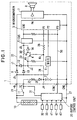
alarm device 1 according to a first embodiment of the present invention is described with reference to Figs 1 - 5. - As shown in Fig. 1, the
alarm device 1 used for anti-theft system for a vehicle is mainly composed of an integratedauxiliary battery 2, a wire-disconnection-detectingcircuit 6, atransistor 4, a constant-voltage-power-source 5, amicrocomputer 3, an amplifying circuit 7 and electric-sound-generator 8. - The
alarm device 1 has a +B terminal which is connected to the plus terminal of avehicle battery 10 mounted on the vehicle through a power-supply wire 21. Electric power is supplied from thebattery 10 through adiode 9 and a power-supply wire 22 to the amplifying unit 7 disposed in thealarm device 1 and through adiode 13, a power-supply wire 23 and aresistor 30 to the constant-voltage-power-source 5. Thealarm device 1 is also connected to an ignition switch 11 through the terminal IG. The other terminal of the ignition switch 11 is connected to the power-supply wire 21. Thealarm device 1 is also connected to anoutside controller 20 through an input terminal CONT and to a ground through a terminal GND. - A power-
supply wire 24 connects the plus terminal of theauxiliary battery 2 to theemitter 4a of thetransistor 4 and the anode of thediode 12 at a junction J2. The cathode of thediode 12 is connected to the power-supply wire 22 at a junction J1. Theauxiliary battery 2 supplies the backup power to the constant-voltage-power-source 5, themicrocomputer 3 and the amplifying unit 7 if the power-supply wire 21 connecting thevehicle battery 10 and the terminal +B is disconnected. - The plus terminal of the
auxiliary battery 2 is connected to the ignition switch 11 through a junction J4, adiode 29, aresistor 25 and the terminal IG. Therefore, when the ignition switch 11 is turned on, electric power is supplied from thebattery 10 to charge theauxiliary battery 2. - The wire-disconnection-detecting
circuit 6 is composed of a diode and a parallelly-connected resistor (not shown) and is connected through the power-supply wire 21 to thevehicle battery 10 and connected to agrounded wire 27 at the terminal GND. When the disconnection of the power-supply wire 21 and groundedwire 27 is detected, a detection signal is transmitted to a port P2 of themicrocomputer 3. - The
transistor 4 is ready for power supply to the constant-voltage-source 5 from thebackup battery 2 when the system is put on the watch. Theemitter 4a of thetransistor 4 is connected to the plus-terminal of thebackup battery 2 at the junction J2. Thebase 4b thereof is connected to the port P1 of themicrocomputer 3 through aresistor 28 and thecollector 4c thereof is connected to the anode of thediode 14. The cathode of thediode 14 is connected to the power-supplyingwire 23 at the junction J3. - The constant-voltage-power-
source 5 is powered by thebattery 10 and theauxiliary battery 2 to supply a constant voltage to themicrocomputer 3 through a terminal VDD. - The
microcomputer 3 receives a detection signal from the wire-disconnection-detectingcircuit 6 and a discrimination signal from theoutside controller 20 through the ports P2 and P3 respectively. Themicrocomputer 3 controls thetransistor 4 to turn on or off according to the above signals and sends an oscillation signal to theelectric sound generator 8 from the output port P4 through the amplifying circuit 7. The amplifying circuit 7 is composed of amplifying elements such as transistors and FETs and amplifies the oscillating signal sent from the output port P4 of themicrocomputer 3. The electric-sound generator 8 converts the signal amplified by the amplifying circuit 7 into an alarming sound. - The
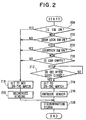
outside controller 20 detects the on/off state of the ignition switch 11 through asignal line 31 and on/off state of a door-lock switch 32 and a door-courtesy switch 33. Theoutside controller 20 determines whether the alarm device is on the watch or not by processing the signals through a process described later. Theoutside controller 20 receives signals from a window-glass sensor 41, anultrasonic sensor 42 and avibration sensor 43 and determines whether abnormal or not by a later-described process according to those signals. Theoutside controller 20 provides one of the discrimination signals such as a watch signal, a watch-free signal or an abnormality signal at the terminal CONT and give it to the port P3 of themicrocomputer 3 through aninput wire 50. - The operation of the
outside controller 20 is described with reference to flow charts shown in Figs. 2 and 3. - The process shown in Fig. 2 is initiated by the on or off signal of the door-lock signal as a interrupt signal. At first, whether the ignition switch 11 is turned on or not is examined (step 204), and whether the door-
lock switch 32 is turned on or not is examined (step 206). If a driver is going to release the door-lock to get in the car while the system is put on the watch, theoutside controller 20 determines NO in thestep 206 and the watch-free condition is set instep 218. Thereafter, the window-glass sensor 41 and thevibration sensor 43 are deenergized (step 220), and a watch-free signal (one of the discrimination signals) is produced (step 228). Theultrasonic sensor 42 is kept energized in thestep 220 in this moment. - Thereafter, the driver releases the door-lock , opens the door, get in the car and turns on the ignition switch 11. When the ignition switch 11 is turned on,
step 204 produces YES, thereby maintaining the watch-free state (step 218). - When the driver stops the car, turns off the ignition switch 11, releases the door lock, opens the door and sets the door lock, the
steps outside controller 20 reads the output signal of theultrasonic sensor 42 and determines that nobody is present in the car (that is, the car is empty), YES is produced instep 210. - Thereafter, if a period of 30 seconds has passed (step 212), it is determined that the driver has left the car and the antii-theft system is put on the watch (step 214). Consequently, the window-
glass sensor 41 and thevibration sensor 43 are energized (step 216), and the watch signal is produced (step 228). If the ignition switch 11 is turned on in thestep 204, the door-lock switch 32 is turned off in thestep 206, the door-courtesy switch 33 is turned on in thestep 208, or somebody is detected in the car, the step is transferred to step 218, where not-on-the watch state is maintained. - In on-the-watch state, whether an abnormal condition is present or not is determined. The watching steps are shown in Fig. 3. Firstly, whether the system is put on the watch or not is determined (step 302). If it is determined that the system is on the watch, signals from the window-
glass sensor 41,ultrasonic sensor 42 andvibration sensor 43 are read instep 304. Subsequently, the abnormal condition is determined according to those signals instep 306. If at least one of those signals indicates the abnormal condition, an abnormality signal is produced instep 308. If the system is maintained on the watch-free in thestep 302 or the abnormal condition is not present in thestep 306, the steps are ended. Thus, the abnormal condition is determined. - The watch signal, the watch-free signal or the abnormality signal is applied by means of the steps shown in Figs. 2 and 3 from the terminal CONT through the
input wire 50 to the port P3 of themicrocomputer 3 of thealarm device 1. The above signals are coded into a pulse train to prevent malfunction of thealarm service 1 due to outside noises. - The operation of the
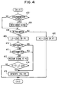
microcomputer 3 is described with reference to a flow-chart shown in Fig. 4. The steps shown in Fig. 4 are executed at certain intervals, and the operation is continued until the next signal is received. - At first, whether or not the discrimination signal is transmitted from the terminal CONT through the port P3 is determined (step 402). If the signal is transmitted, the signal is read according to a discrimination program written in an inside memory (ROM, not shown) of the
microcomputer 3, and thealarm device 1 is put on the watch according to the signal (step 404). If the signal is not received, in thestep 402, whether the system is on the watch or not at present is determined (404). - If the system is on the watch, YES is produced in
step 406 and the output signal of the port P1 becomes Lo-level(step 408), which turns on thetransistor 4 to connect theauxiliary battery 2 to the constant-voltage-source 5. Then, the presence of the abnormality is examined (step 410). If the abnormality is not present, NO is produced in thestep 410, and whether the input wire is disconnected or not is determined in thenext step 411. - The
transistor 4 is the PNP-type and the potential of thebase 4b thereof becomes Hi-level on account of the auxiliary battery to turn off at the initial stage (the output terminals of the microcomputer are open). Themicrocomputer 3 is open-drain type, and the base potential at the initial stage becomes Hi-level in this embodiment. However if themicrocomputer 3 is a sink drain type, thetransistor 4 is required to be the NPN-type because the potential of the base thereof at the initial stage becomes Lo-level. - If the
transistor 4 is turned on and the power-supply-wire 21 and the grounded-wire 27 normally connect thebattery 10 and thealarm device 1, the potential of the junctions J1 and J3 becomes higher than a voltage which is left after subtracting the voltage drop of thediodes auxiliary battery 2 so that the constant-voltage source 5 and the amplifying circuit 7 are energized from thevehicle battery 10 through the terminal +B. - After the port P1 becomes Lo-level in the
step 408, themicrocomputer 3 receives a signal at the port P2 (step 412) and determines whether it is Lo-level or not (step 414). The port P2 is connected to the wire-disconnection-detectingcircuit 6 which is connected to the power-supply-wire 21, the Lo-level signal sent to the port P2 indicates that the power-source-wire is disconnected by somebody and the potential of the +B terminal disappears. If the power-supply-wire 21 is disconnected, the potential of the junctions J1 and J2 becomes lower than the terminal voltage of theauxiliary battery 2, and the constant-voltage-source 5 and the amplifying circuit 7 are energized by theauxiliary battery 2. If the port P2 becomes Lo-level, themicrocomputer 3 energizes the amplifying circuit 7 and generates the oscillating signal according to a program (step 416). The oscillating signal is converted through the amplifying circuit 7 to an alarming sound of about 120 decibel by theelectric sound generator 8. - If the input signal sent from the port P2 is not the Lo-level signal in the
step 414, it is determined that the power-supply-wire is not disconnected, and the step is ended. If it is determined that the abnormality is present in thestep 410 or that theinput wire 50 is disconnected in thestep 411, YES is determined in the respective steps, and the amplifying circuit 7 is energized and the oscillating signal is generated in thestep 416 to sound the alarm. If the system is not on the watch in thestep 406, the output voltage of the port P1 becomes the initial level (Hi-level, step 420 ). In thestep 420, thetransistor 4 is turned off, and the constant-voltage-source 5 is not energized by theauxiliary battery 2. Therefore, even if the power-supply-wire 21 is disconnected from thebattery 10, the power is not supplied from theauxiliary battery 2. - Before the
alarm device 1 is installed in the vehicle, in other words, if thealarm device 1 is not connected to the power-supply-wire 21 or the signal wires from theoutside controller 20, themicrocomputer 3 is not energized and thetransistor 4 maintains the off state to deenergize the constant-voltage-source 5. Thus, the electric supply from thebattery 2 before installation is cut so that theauxiliary battery 2 is prevented from lowering the charging voltage, thereby preventing thealarm device 1 from alarming when it is dismounted from the vehicle for a maintenance service. - The states of the
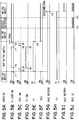
alarm device 1 being on the watch or not on the watch and the operation of thealarm device 1 when the disconnection takes place are shown in a timing chart in Figs 5A - 5J. - When a watch signal indicates the state of the system on the watch, the port P1 becomes Lo-level as shown in Fig. 5E, and the
transistor 4 is turned on as shown in Fig. 5F. Thus, the constant-voltage-source 5 and the amplifying circuit 7 are powered from one of the junctions J1, J2 and J3 whose potential is the highest. Because the potential (12 V) of the junctions J1 and J3 is higher than the potential (about 4 - 8 volt) of thejunction 4, the constant-voltage-source 5 and the amplifying circuit 7 are powered by thevehicle battery 10 as shown in Fig. 7G. Therefore, the power supply is not carried out by theauxiliary battery 2 as shown in Fig. 5I. As long as the power-supply-wire 21 is not disconnected, theport 2 maintains the Hi-level voltage as shown in Fig. 5H. - If a driver releases the door lock at time t1, a signal indicating not-on-the watch as shown in Fig. 5A is sent from the
outside controller 20, the port P1 becomes Hi-level as shown in Fig. 5E and thetransistor 4 is turned off as shown in Fig. 5F. If the driver starts the engine in a period t4 - t5 in Fig. 5D and gets out of the car and, subsequently, sets the door lock at time t10 as shown in Fig. 5B, the watch-free state continues for 30 seconds. - The
transistor 4 is turned off while the system is put on the watch-free and, therefore, power supply to the constant voltage-source 5 is not furnished by theauxiliary battery 2 but furnished by thevehicle battery 10 as shown in Figs. 5G and 5I. - At time t11 when 30 seconds passed after the door-lock is set as shown in Fig. 5B, the port P1 becomes Lo-level as shown in Fig. 5E, and the
transistor 4 is turned on as shown in Fig. 5F. Thus, the power supply from theauxiliary battery 2 becomes available. - If at least one of the window-
glass sensor 41, ultrasonic sensor, 42 andvibration sensor 43 detects an abnormal condition at time t12, an oscillation signal is sent from the port P4 as shown in Fig. 5J, and theelectric sound generator 8 sounds the alarm. The oscillation signal continues until time t13 when the abnormal condition is eliminated. - If disconnection of the power-supply-
wire 21 is detected at time t14, the port P2 becomes Lo-level as shown in Fig. 5H, the power supply from thevehicle battery 10 to the constant-voltage-power-source 5 and the amplifying circuit 7 is cut as shown in Fig. 5G, and the power supply from theauxiliary battery 2 is started as shown in Fig. 5 I. If the port P2 becomes Lo-level, themicrocomputer 3 determines that the wire-disconnection is present and provides the oscillation signal as shown in Fig. 5J, and the electric-sound-generator 8 sounds the alarm. - According to the above structure, the
alarm device 1 has theauxiliary battery 2 which is separate from thevehicle battery 10 and receives the watch signal and watch-free signal. When the system is put on the watch and an abnormal condition is detected, it gives an alarm. If the system is put on the watch, thetransistor 4 is turned on to connect theauxiliary battery 2 to themicrocomputer 3. Therefore, if the power-supply-wire 21 and the groundedwire 27 are disconnected, the disconnection is detected by the wire-disconnection-detecting-circuit 6 so that theelectric sound generator 8 sounds the alarm. If thevehicle battery 10 and thealarm device 1 are disconnected from each other for the maintenance service under the watch-free state, thetransistor 4 is turned off to cut the power supply to themicrocomputer 3 from theauxiliary battery 2, thereby deactivating the electric-sound generator 8 which gives the alarm. As a result, no specific operation is necessary to cut the electric connection between thevehicle battery 10 and thealarm device 1 and to prevent the alarm-sounding. - In more detail, when the outside controller determines that the system is on the watch, the microcomputer turns on the
transistor 4 to make use of theauxiliary battery 2. Thus, if one of theultrasonic sensor 42 for detecting the access to the vehicle compartment, the window-glass-sensor 41 for detecting breakage of the windows, thevibration sensor 43 for detecting the vibrations of the vehicle detects the abnormal condition, the constant-voltage-source 5 and the amplifying circuit 7 are energized by thevehicle battery 10 to drive the electric-sound generator 8. If the wire-disconnection-detecting-circuit 6 detects disconnection of the power-supply-wire 21 connecting themicrocomputer 3 and thevehicle battery 10 and the groundedwire 27, theauxiliary battery 2 energizes the constant-voltage-source 5 and the amplifying circuit 7 to drive the electric-sound generator 8, thereby sounding the alarm. If thevehicle battery 10 and the alarm device are disconnected for a maintenance service in the watch-free state, thetransistor 4 is turned off to prevent theauxiliary battery 2 from energizing the constant-voltage source 5, thereby deactivating the electric-sound generator 8. - Because either the watch signal or the watch-free signal is transmitted to the
microcomputer 3 through theinput wire 50 and themicrocomputer 3 determines whether the vehicle is on the watch or not, any separate input wire other than theinput wire 50 is not necessary. If theinput wire 50 is disconnected when the vehicle is on the watch, themicrocomputer 3 drives the electric-sound-generator 8 through the amplifying circuit 7 to sound the alarm. Therefore, thealarm device 1 provide a high security. - Further, a signal indicating an abnormal condition is sent to the
microcomputer 3 through theinput wire 50 from one of theultrasonic sensor 42, window-glass-sensor 41,vibration sensor 43. Therefore, no wires in addition to theinput wire 50 is necessary, and thealarm device 1 has a small number of parts. - The
auxiliary battery 2 supplies power only when the power-supply-wire 21 is disconnected while the system is put on the watch. Therefore, theauxiliary battery 2 is prevented from supplying unnecessary power so that the charged power of theauxiliary battery 2 may not lowers when it is shipped. - A
reference numeral 13 indicates a diode for preventing problem due to the reverse connection. - Fig. 6 is a schematic circuit diagram showing an
alarm device 101 according to a second embodiment of the present invention. The power from theauxiliary battery 2 in this embodiment is supplied only through thetransistor 4 to the power-supply-wire 22, and the constant-voltage-source 5 is energized through the power-supply-wire 22 and aresistor 26. - As shown in Fig. 6, a
diode 18 is connected between thetransistor 4 and the power-supply-wire 22 with the cathode thereof connected to a junction J6 of the power-supply-wire 22 and the anode thereof connected to connected to the collector of thetransistor 4. The power-supply-wire 23 is connected between the constant-voltage-source 5 and a junction J7 through aresistor 26. The junction J7 is located on the power-supply-wire 22 between thediode 9 and the junction J6. Thediodes - In the
alarm device 101 according to the above embodiment, the constant-voltage-source 5 and the amplifying circuit 7 are energized by thevehicle battery 10 through the power-supply-wires wire 21 is disconnected, the power is not supplied from thevehicle battery 10 but is supplied to the amplifying circuit 7 from theauxiliary battery 2 through thetransistor 4,diode 18 and the power-supply-wire 22 and to the constant-voltage-source 5 throughresistor 26 and the power-supply-wire 23. - On the other hand, when the system is not put on the watch, the
transistor 4 is turned off by the signal sent from themicrocomputer 3 so that the power is not supplied to the constant-voltage-source 5 and the amplifying circuit 7 from theauxiliary battery 2. - As a result, the
auxiliary battery 2 is allowed to supply power when the car is on the watch, which results in the same effect as the first embodiment. The above embodiment has reduced number of diodes as compared with the first embodiment, resulting in a simpler structure. - The
transistor 4 can be replaced with MOSFET or a relay which functions to switch over the current path. - The window-
glass sensor 41, theultrasonic sensor 42 and thevibration sensor 43 of the above embodiment can be replaced with any other sensor for detecting the abnormal condition. For example, a clinometer can be used to detect a degree of the inclination of the vehicle and gives the alarm when the degree exceeds a threshold level. A vehicle speed sensor or an infrared sensor or the like can be also used to detect the abnormal condition of the vehicle. - The
alarm devices - The present invention is not limited to the anti-theft system. For example, it is applied to an alarm device for a system other than the anti-theft system which gives the alarm when the system gets into trouble.
- An alarm device (1) of an anti-theft system for a vehicle is composed of a microcomputer (3) ordinary connected by a power-supply wire (21,27) to a main battery (10), an electric-sound-generator (8) driven by the microcomputer (3), a wire-disconnection-detecting-circuit (6) for detecting disconnection of the power-supply-wire (21,27) of the alarm device (1) from a main battery (10), an integrated auxiliary battery (2) connected to the microcomputer (3) and the sound-generator (8), a transistor (4) for cutting power supply to the microcomputer (3) from the auxiliary battery (2) when the anti-theft system is not on the watch, sensors (32,33) for detecting access to the vehicle compartment and an outside controller (20) connected to the sensors to turn on the transistor when the system is on the watch and turns off the transistor (4) when the system is not on the watch. If the access to the vehicle compartment or wire-disconnection is detected while the anti-theft system is on the watch, the microcomputer (3) drives the sound-generator (8) to give the alarm.
Claims (7)
- An alarm device (1) having an integrated auxiliary battery (2) for an alarming system including a main battery (10), an outside controller (20) for producing a watch signal putting said system on the watch and a watch-free signal releasing said system from being on the watch, said alarm device (1) comprising:an alarming-sound generator (8);a driving unit (3), connected to said main battery (10) and said auxiliary battery (2), for driving said alarming-sound generator (8);a wire-disconnection-detecting unit (6) for detecting electrical-disconnection of said driving unit (3) from said main battery (10); anda changeover unit (4), connected between said auxiliary battery (2) and said driving unit (3), for changing over from one to another between power-supply of said auxiliary battery (2) and power-cut thereof according to said watch signal and watch-free signal; whereinif said system is on the watch, said changeover unit (4) supplies power from said auxiliary battery (2) to activate said alarming-sound generator (8) when said wire-disconnection-detecting unit (6) detects disconnection of said main battery (10), and
if said system is not on the watch, said changeover unit (4) cut power from said auxiliary battery (2) to said driving unit (3) to deactivate said alarming-sound generator (8). - An alarm device (1) as claimed in claim 1, wherein
said driving unit (3) is connected to said outside controller (20) by a single input-wire (50) to receive said watch signal and watch-free signal so that said driving unit (3) activates said alarming-sound generator (8) if said single input-wire (50) is disconnected while said system is put on the watch. - An alarm device (1) as claimed in claim 1 further comprising an abnormality-detecting sensor (41,42,43), connected to said outside controller (20), for detecting an abnormal condition of said system; wherein
said outside controller (20) sends an abnormality signal to said driving unit (3) through said single input-wire (50) together with said watch signal and watch-free signal, and
said driving unit (3) discriminates respective signals. - An alarm device (1) having an integrated auxiliary battery (2) for an alarming system for a vehicle including a main battery (10), said alarm device (1) comprising:means (20), connected to an ignition switch (11) and having a sensor (32,33)to detect an operation of said vehicle, for determining whether said vehicle is on the watch or not according to a signal of said sensor (32,33);an alarming-sound generator (8) for sounding when said vehicle is in an abnormal state;a driving unit (3) for activating said alarming-sound generator (8);an integrated auxiliary battery (2) connected to said driving unit (3);a disconnection-detecting unit (6) for detecting disconnection of said driving unit (3) from said main battery (10); anda changeover unit (4) connected between said driving unit (3) and said auxiliary battery (2) for changing over one from another between activating said driving unit (3) and deactivating said driving unit (3); whereinwhen said determining means determines that said system is on the watch, said changeover unit (4) renders said auxiliary battery (2) ready for power supply, if said abnormality-detecting-unit detects an abnormality, said alarming-sound generator (8) is energized and activated by said main battery (10), if said disconnection-detecting unit (6) detects a disconnection of said alarm device (1) from one of said main battery (10) and said outside controller (20), said alarming-sound generator (8) is activated by said auxiliary battery (2); and
when said determining means determines that said system is not on the watch, said changeover unit (4) renders said auxiliary battery (2) isolated to deactivate said alarming-sound generator (8). - A alarm device (1) as claimed in claim 1, wherein
said determining means (20) further includes a door lock switch (32) and determines that said system is on the watch when said ignition switch (11) is turned off and a door-lock switch (32) is turned off, and determines that said system is not on the watch when said ignition switch (11) is turned on and said door-lock switch (32) is turned off. - An anti-theft system for a vehicle including a main battery (10), an ignition switch (11), a sensor (32,33) for detecting access to a compartment of said vehicle, a control unit (20) connected to said ignition switch (11) and said access-detecting sensor (32, 33) for determining whether said system is on the watch or not and an alarm device (1) connected to said main battery (10) for and said control unit (20); wherein said alarm device (1) comprises:an integrated auxiliary battery (2);an alarming-sound generator (8) for sounding when energized:a disconnection-detecting unit (6) for detecting disconnection of said alarm device (1) from said main battery (10);a driving unit (3), connected to said disconnection-detecting unit (6) and said control unit (20), for activating said alarming-sound generator (8) if said driving unit (3) is supplied with power;
andmeans (4), connected to said auxiliary battery (2) and said driving unit (3), for supplying power from said auxiliary battery (2) to said driving unit (3) and said alarming-sound generator (8) when said system is on the watch and said disconnection-detecting unit (6) detects a disconnection of said alarm device (1) from said main battery (10). - An anti-theft system as claimed in claim 6, further comprising a door-lock switch (32) for sensing operation of a door lock, wherein
said control unit (20) determines that said system is on the watch when said ignition switch (11) is turned off and a door-lock switch (32) is turned off, and that said system is not on the watch when said ignition switch (11) is turned on and said door-lock switch (32) is turned off.
Applications Claiming Priority (6)
| Application Number | Priority Date | Filing Date | Title |
|---|---|---|---|
| JP34662995 | 1995-12-12 | ||
| JP346629/95 | 1995-12-12 | ||
| JP34662995 | 1995-12-12 | ||
| JP28023096 | 1996-09-30 | ||
| JP280230/96 | 1996-09-30 | ||
| JP28023096A JP3493917B2 (en) | 1995-12-12 | 1996-09-30 | Alarm device |
Publications (3)
| Publication Number | Publication Date |
|---|---|
| EP0780820A2 true EP0780820A2 (en) | 1997-06-25 |
| EP0780820A3 EP0780820A3 (en) | 1998-04-15 |
| EP0780820B1 EP0780820B1 (en) | 2004-02-25 |
Family
ID=26553690
Family Applications (1)
| Application Number | Title | Priority Date | Filing Date |
|---|---|---|---|
| EP19960119866 Revoked EP0780820B1 (en) | 1995-12-12 | 1996-12-11 | Alarm device having integrated battery |
Country Status (4)
| Country | Link |
|---|---|
| US (1) | US5774044A (en) |
| EP (1) | EP0780820B1 (en) |
| JP (1) | JP3493917B2 (en) |
| DE (1) | DE69631640T2 (en) |
Cited By (5)
| Publication number | Priority date | Publication date | Assignee | Title |
|---|---|---|---|---|
| EP1099605A1 (en) * | 1999-05-18 | 2001-05-16 | Mitsubishi Denki Kabushiki Kaisha | Emergency call system with battery switching function |
| WO2001049536A1 (en) * | 1999-12-30 | 2001-07-12 | Scania Cv Aktiebolag (Publ) | Alarm system for a motor vehicle |
| EP1975018A1 (en) * | 2007-03-30 | 2008-10-01 | Delphi Technologies, Inc. | Alarm device for an automobile |
| EP2404792A1 (en) * | 2009-03-06 | 2012-01-11 | Honda Motor Co., Ltd. | Abnormality detection and vehicle tracking device |
| CN113302094A (en) * | 2019-01-31 | 2021-08-24 | 本田技研工业株式会社 | Vehicle remote control system, vehicle remote control method, server, terminal device, and communication device |
Families Citing this family (18)
| Publication number | Priority date | Publication date | Assignee | Title |
|---|---|---|---|---|
| JPH09212261A (en) * | 1996-01-31 | 1997-08-15 | Hitachi Ltd | Power supply control system for information processor |
| JP2001037078A (en) * | 1999-07-16 | 2001-02-09 | Alps Electric Co Ltd | Low power consumption on-vehicle control equipment |
| US6195605B1 (en) * | 1999-09-29 | 2001-02-27 | Bmi Technologies Inc. | Impact monitor |
| JP3687466B2 (en) * | 2000-02-23 | 2005-08-24 | 株式会社デンソー | Vehicle position reporting device and vehicle position reporting system |
| US6392316B1 (en) * | 2000-03-20 | 2002-05-21 | Matsushita Electric Industrial Co., Ltd. | Emergency informing apparatus |
| JP3770589B2 (en) * | 2000-08-09 | 2006-04-26 | 矢崎総業株式会社 | Vehicle tracking system, vehicle burglar alarm system, stolen vehicle tracking system, and burglar alarm vehicle tracking system |
| KR20010044543A (en) * | 2001-03-06 | 2001-06-05 | 이남용 | Alarm unit for the car hands free system |
| JP4949736B2 (en) * | 2006-05-24 | 2012-06-13 | 三菱電線工業株式会社 | Charging device for vehicle abnormality detection device |
| CN100408391C (en) * | 2006-06-16 | 2008-08-06 | 北京中科三环高技术股份有限公司 | Intelligent alarming anti-theft brushless controller for electric vehicle |
| US8081074B2 (en) * | 2007-09-11 | 2011-12-20 | Marshall Jack L | Security system for protecting construction site assets |
| JP4831113B2 (en) * | 2008-04-28 | 2011-12-07 | ブラザー工業株式会社 | Battery connection detecting device and image forming apparatus having the same |
| JP5419496B2 (en) * | 2009-03-06 | 2014-02-19 | 本田技研工業株式会社 | Anomaly detection and vehicle tracking device |
| JP5419495B2 (en) * | 2009-03-06 | 2014-02-19 | 本田技研工業株式会社 | Anomaly detection and vehicle tracking device |
| JP4885999B2 (en) * | 2009-03-30 | 2012-02-29 | ホーチキ株式会社 | Alarm |
| KR101877995B1 (en) * | 2012-09-06 | 2018-07-13 | 현대자동차주식회사 | Apparatus for preventing robbery for vehicle |
| US9437100B2 (en) * | 2013-11-02 | 2016-09-06 | Jeffrey D. Zwirn | Supervising alarm notification devices |
| EP3802224A1 (en) * | 2018-06-01 | 2021-04-14 | HUF Hülsbeck & Fürst GmbH & Co. KG | Authentication system and security procedure therefor |
| CN111824063B (en) * | 2019-04-17 | 2022-03-08 | 北京新能源汽车股份有限公司 | Power battery anti-theft system and car |
Family Cites Families (10)
| Publication number | Priority date | Publication date | Assignee | Title |
|---|---|---|---|---|
| US3656102A (en) * | 1970-06-01 | 1972-04-11 | David A Hale | Vehicular antitheft device having relay switches for interrupting induction coil circuit and for activating an alarm |
| US3815088A (en) * | 1972-12-04 | 1974-06-04 | Sheldon Aircraft Prod Corp | Vehicle alarm circuit responsive to selected battery voltage transients |
| FR2437958A1 (en) * | 1978-10-02 | 1980-04-30 | Prudhomme Christian | Motor vehicle antitheft alarm system - has vibration sensor and RC delay circuit allowing driver to dismount |
| US4761631A (en) * | 1987-05-14 | 1988-08-02 | Hwang Shih Ming | Main battery disconnection alarm and headlight warning circuit |
| JPS6490846A (en) * | 1987-09-30 | 1989-04-07 | Shiroki Corp | Burglarproof device for automobile |
| FR2653920A1 (en) * | 1989-11-02 | 1991-05-03 | Texton | Alarm system especially for a motor vehicle, with an independent electrical energy source |
| US5153558A (en) * | 1991-02-08 | 1992-10-06 | Delco Electronics Corp. | Vehicle security system with battery tampering detection |
| GB2272337B (en) * | 1992-11-05 | 1997-05-21 | Clifford Electronics Inc | Vehicle security system siren with backup rechargeable battery |
| US5473200A (en) * | 1993-10-08 | 1995-12-05 | Depromax Limited | Frequency modulation digital code anti-theft system |
| JP2943976B2 (en) * | 1995-02-17 | 1999-08-30 | 本田技研工業株式会社 | Engine control device with vehicle anti-theft function |
-
1996
- 1996-09-30 JP JP28023096A patent/JP3493917B2/en not_active Expired - Fee Related
- 1996-12-11 DE DE1996631640 patent/DE69631640T2/en not_active Revoked
- 1996-12-11 US US08/764,021 patent/US5774044A/en not_active Expired - Fee Related
- 1996-12-11 EP EP19960119866 patent/EP0780820B1/en not_active Revoked
Non-Patent Citations (1)
| Title |
|---|
| None |
Cited By (11)
| Publication number | Priority date | Publication date | Assignee | Title |
|---|---|---|---|---|
| EP1099605A1 (en) * | 1999-05-18 | 2001-05-16 | Mitsubishi Denki Kabushiki Kaisha | Emergency call system with battery switching function |
| EP1099605A4 (en) * | 1999-05-18 | 2004-12-08 | Mitsubishi Electric Corp | Emergency call system with battery switching function |
| WO2001049536A1 (en) * | 1999-12-30 | 2001-07-12 | Scania Cv Aktiebolag (Publ) | Alarm system for a motor vehicle |
| US7046156B2 (en) | 1999-12-30 | 2006-05-16 | Scania Cv Ab (Publ) | Alarm system for a motor vehicle |
| EP1975018A1 (en) * | 2007-03-30 | 2008-10-01 | Delphi Technologies, Inc. | Alarm device for an automobile |
| EP2404792A1 (en) * | 2009-03-06 | 2012-01-11 | Honda Motor Co., Ltd. | Abnormality detection and vehicle tracking device |
| CN102341281A (en) * | 2009-03-06 | 2012-02-01 | 本田技研工业株式会社 | Abnormality detection and vehicle tracking device |
| EP2404792A4 (en) * | 2009-03-06 | 2012-08-22 | Honda Motor Co Ltd | Abnormality detection and vehicle tracking device |
| CN102341281B (en) * | 2009-03-06 | 2013-10-09 | 本田技研工业株式会社 | Abnormality detection and vehicle tracking device |
| CN113302094A (en) * | 2019-01-31 | 2021-08-24 | 本田技研工业株式会社 | Vehicle remote control system, vehicle remote control method, server, terminal device, and communication device |
| CN113302094B (en) * | 2019-01-31 | 2023-05-02 | 本田技研工业株式会社 | Vehicle remote control system, vehicle remote control method, server, terminal device, and communication device |
Also Published As
| Publication number | Publication date |
|---|---|
| JP3493917B2 (en) | 2004-02-03 |
| EP0780820B1 (en) | 2004-02-25 |
| EP0780820A3 (en) | 1998-04-15 |
| US5774044A (en) | 1998-06-30 |
| DE69631640D1 (en) | 2004-04-01 |
| DE69631640T2 (en) | 2004-09-30 |
| JPH09223278A (en) | 1997-08-26 |
Similar Documents
| Publication | Publication Date | Title |
|---|---|---|
| US5774044A (en) | Alarm device having integrated battery | |
| US6317034B1 (en) | Alarm sensor multiplexing | |
| JPS60222309A (en) | Level-control device for automobile | |
| KR19980702718A (en) | Alarm Sensor Multiplexing | |
| GB2272337A (en) | Vehicle security system siren with back-up rechargeable battery | |
| EP0901112B1 (en) | Display system for burglary-preventing device | |
| EP0635409B1 (en) | An automobile and an alarm system in combination | |
| US7023329B2 (en) | Air pressure induction type vehicle anti-thief device | |
| JP2000344054A (en) | Antitheft device for vehicle | |
| JPH01223051A (en) | Robbery preventing device for car | |
| KR0140490B1 (en) | Apparatus for opening and closing window by a hand in the case of accident | |
| KR100190403B1 (en) | A protective system for a car | |
| CN214450817U (en) | Drunk driving prevention control device with anti-theft disturbance prompt function | |
| GB2143977A (en) | Burglar alarm system for a vehicle or the like | |
| JPH0769174A (en) | Anti-theft system for vehicle | |
| JPH09203364A (en) | Engine remote starting device for automobile engine | |
| JPH09170534A (en) | Engine starting device | |
| JP3170978B2 (en) | Vehicle anti-theft device | |
| GB2368440A (en) | Car security alarm sensing battery voltage change | |
| KR19980051319A (en) | Anti-theft system | |
| JP3180355B2 (en) | Automotive air purifier | |
| KR100217598B1 (en) | Anti-theft vehicle security system | |
| JP2002200968A (en) | Theft preventing device | |
| JPH0757161A (en) | Vehicle theft alarming device | |
| JPS62221953A (en) | Burglary preventing device |
Legal Events
| Date | Code | Title | Description |
|---|---|---|---|
| PUAI | Public reference made under article 153(3) epc to a published international application that has entered the european phase |
Free format text: ORIGINAL CODE: 0009012 |
|
| AK | Designated contracting states |
Kind code of ref document: A2 Designated state(s): DE GB SE |
|
| PUAL | Search report despatched |
Free format text: ORIGINAL CODE: 0009013 |
|
| AK | Designated contracting states |
Kind code of ref document: A3 Designated state(s): DE GB SE |
|
| 17P | Request for examination filed |
Effective date: 19980807 |
|
| 17Q | First examination report despatched |
Effective date: 20010918 |
|
| GRAH | Despatch of communication of intention to grant a patent |
Free format text: ORIGINAL CODE: EPIDOS IGRA |
|
| GRAS | Grant fee paid |
Free format text: ORIGINAL CODE: EPIDOSNIGR3 |
|
| GRAA | (expected) grant |
Free format text: ORIGINAL CODE: 0009210 |
|
| AK | Designated contracting states |
Kind code of ref document: B1 Designated state(s): DE GB SE |
|
| REG | Reference to a national code |
Ref country code: GB Ref legal event code: FG4D |
|
| REG | Reference to a national code |
Ref country code: SE Ref legal event code: TRGR |
|
| REF | Corresponds to: |
Ref document number: 69631640 Country of ref document: DE Date of ref document: 20040401 Kind code of ref document: P |
|
| PLBI | Opposition filed |
Free format text: ORIGINAL CODE: 0009260 |
|
| PLAX | Notice of opposition and request to file observation + time limit sent |
Free format text: ORIGINAL CODE: EPIDOSNOBS2 |
|
| 26 | Opposition filed |
Opponent name: DAIMLERCHRYSLER AG Effective date: 20041125 |
|
| REG | Reference to a national code |
Ref country code: GB Ref legal event code: 746 Effective date: 20050210 |
|
| PLBB | Reply of patent proprietor to notice(s) of opposition received |
Free format text: ORIGINAL CODE: EPIDOSNOBS3 |
|
| PLAY | Examination report in opposition despatched + time limit |
Free format text: ORIGINAL CODE: EPIDOSNORE2 |
|
| PLAH | Information related to despatch of examination report in opposition + time limit modified |
Free format text: ORIGINAL CODE: EPIDOSCORE2 |
|
| PLBC | Reply to examination report in opposition received |
Free format text: ORIGINAL CODE: EPIDOSNORE3 |
|
| PGFP | Annual fee paid to national office [announced via postgrant information from national office to epo] |
Ref country code: SE Payment date: 20061206 Year of fee payment: 11 Ref country code: GB Payment date: 20061206 Year of fee payment: 11 |
|
| PGFP | Annual fee paid to national office [announced via postgrant information from national office to epo] |
Ref country code: DE Payment date: 20061207 Year of fee payment: 11 |
|
| RDAF | Communication despatched that patent is revoked |
Free format text: ORIGINAL CODE: EPIDOSNREV1 |
|
| RDAG | Patent revoked |
Free format text: ORIGINAL CODE: 0009271 |
|
| STAA | Information on the status of an ep patent application or granted ep patent |
Free format text: STATUS: PATENT REVOKED |
|
| 27W | Patent revoked |
Effective date: 20070110 |
|
| GBPR | Gb: patent revoked under art. 102 of the ep convention designating the uk as contracting state |
Free format text: 20070110 |
|
| REG | Reference to a national code |
Ref country code: SE Ref legal event code: ECNC |