EP0780256B1 - Verfahren zum Anfahren mit Energierückgewinnung für Hybridfahrzeug - Google Patents
Verfahren zum Anfahren mit Energierückgewinnung für Hybridfahrzeug Download PDFInfo
- Publication number
- EP0780256B1 EP0780256B1 EP96203167A EP96203167A EP0780256B1 EP 0780256 B1 EP0780256 B1 EP 0780256B1 EP 96203167 A EP96203167 A EP 96203167A EP 96203167 A EP96203167 A EP 96203167A EP 0780256 B1 EP0780256 B1 EP 0780256B1
- Authority
- EP
- European Patent Office
- Prior art keywords
- speed
- vehicle
- gear set
- output member
- torque
- Prior art date
- Legal status (The legal status is an assumption and is not a legal conclusion. Google has not performed a legal analysis and makes no representation as to the accuracy of the status listed.)
- Expired - Lifetime
Links
- 238000000034 method Methods 0.000 title claims description 10
- 230000001172 regenerating effect Effects 0.000 title description 13
- 238000002485 combustion reaction Methods 0.000 claims description 16
- 238000006243 chemical reaction Methods 0.000 claims description 8
- 230000008878 coupling Effects 0.000 claims description 8
- 238000010168 coupling process Methods 0.000 claims description 8
- 238000005859 coupling reaction Methods 0.000 claims description 8
- 230000003068 static effect Effects 0.000 claims description 6
- 238000012546 transfer Methods 0.000 claims description 4
- 230000005540 biological transmission Effects 0.000 description 55
- 230000006870 function Effects 0.000 description 17
- 239000012530 fluid Substances 0.000 description 9
- 230000004044 response Effects 0.000 description 7
- 150000001875 compounds Chemical class 0.000 description 3
- 230000001276 controlling effect Effects 0.000 description 3
- 238000010586 diagram Methods 0.000 description 3
- 230000000694 effects Effects 0.000 description 3
- 238000012545 processing Methods 0.000 description 3
- 230000003750 conditioning effect Effects 0.000 description 2
- 230000001133 acceleration Effects 0.000 description 1
- 230000033228 biological regulation Effects 0.000 description 1
- 238000004891 communication Methods 0.000 description 1
- 230000001143 conditioned effect Effects 0.000 description 1
- 239000000470 constituent Substances 0.000 description 1
- 238000007796 conventional method Methods 0.000 description 1
- 239000002826 coolant Substances 0.000 description 1
- 238000001816 cooling Methods 0.000 description 1
- 230000037406 food intake Effects 0.000 description 1
- 239000000446 fuel Substances 0.000 description 1
- 230000006698 induction Effects 0.000 description 1
- 230000000977 initiatory effect Effects 0.000 description 1
- 238000005461 lubrication Methods 0.000 description 1
- 238000012544 monitoring process Methods 0.000 description 1
- 230000001105 regulatory effect Effects 0.000 description 1
- 230000003252 repetitive effect Effects 0.000 description 1
Images

Classifications
-
- B—PERFORMING OPERATIONS; TRANSPORTING
- B60—VEHICLES IN GENERAL
- B60K—ARRANGEMENT OR MOUNTING OF PROPULSION UNITS OR OF TRANSMISSIONS IN VEHICLES; ARRANGEMENT OR MOUNTING OF PLURAL DIVERSE PRIME-MOVERS IN VEHICLES; AUXILIARY DRIVES FOR VEHICLES; INSTRUMENTATION OR DASHBOARDS FOR VEHICLES; ARRANGEMENTS IN CONNECTION WITH COOLING, AIR INTAKE, GAS EXHAUST OR FUEL SUPPLY OF PROPULSION UNITS IN VEHICLES
- B60K6/00—Arrangement or mounting of plural diverse prime-movers for mutual or common propulsion, e.g. hybrid propulsion systems comprising electric motors and internal combustion engines ; Control systems therefor, i.e. systems controlling two or more prime movers, or controlling one of these prime movers and any of the transmission, drive or drive units Informative references: mechanical gearings with secondary electric drive F16H3/72; arrangements for handling mechanical energy structurally associated with the dynamo-electric machine H02K7/00; machines comprising structurally interrelated motor and generator parts H02K51/00; dynamo-electric machines not otherwise provided for in H02K see H02K99/00
- B60K6/20—Arrangement or mounting of plural diverse prime-movers for mutual or common propulsion, e.g. hybrid propulsion systems comprising electric motors and internal combustion engines ; Control systems therefor, i.e. systems controlling two or more prime movers, or controlling one of these prime movers and any of the transmission, drive or drive units Informative references: mechanical gearings with secondary electric drive F16H3/72; arrangements for handling mechanical energy structurally associated with the dynamo-electric machine H02K7/00; machines comprising structurally interrelated motor and generator parts H02K51/00; dynamo-electric machines not otherwise provided for in H02K see H02K99/00 the prime-movers consisting of electric motors and internal combustion engines, e.g. HEVs
- B60K6/22—Arrangement or mounting of plural diverse prime-movers for mutual or common propulsion, e.g. hybrid propulsion systems comprising electric motors and internal combustion engines ; Control systems therefor, i.e. systems controlling two or more prime movers, or controlling one of these prime movers and any of the transmission, drive or drive units Informative references: mechanical gearings with secondary electric drive F16H3/72; arrangements for handling mechanical energy structurally associated with the dynamo-electric machine H02K7/00; machines comprising structurally interrelated motor and generator parts H02K51/00; dynamo-electric machines not otherwise provided for in H02K see H02K99/00 the prime-movers consisting of electric motors and internal combustion engines, e.g. HEVs characterised by apparatus, components or means specially adapted for HEVs
- B60K6/36—Arrangement or mounting of plural diverse prime-movers for mutual or common propulsion, e.g. hybrid propulsion systems comprising electric motors and internal combustion engines ; Control systems therefor, i.e. systems controlling two or more prime movers, or controlling one of these prime movers and any of the transmission, drive or drive units Informative references: mechanical gearings with secondary electric drive F16H3/72; arrangements for handling mechanical energy structurally associated with the dynamo-electric machine H02K7/00; machines comprising structurally interrelated motor and generator parts H02K51/00; dynamo-electric machines not otherwise provided for in H02K see H02K99/00 the prime-movers consisting of electric motors and internal combustion engines, e.g. HEVs characterised by apparatus, components or means specially adapted for HEVs characterised by the transmission gearings
- B60K6/365—Arrangement or mounting of plural diverse prime-movers for mutual or common propulsion, e.g. hybrid propulsion systems comprising electric motors and internal combustion engines ; Control systems therefor, i.e. systems controlling two or more prime movers, or controlling one of these prime movers and any of the transmission, drive or drive units Informative references: mechanical gearings with secondary electric drive F16H3/72; arrangements for handling mechanical energy structurally associated with the dynamo-electric machine H02K7/00; machines comprising structurally interrelated motor and generator parts H02K51/00; dynamo-electric machines not otherwise provided for in H02K see H02K99/00 the prime-movers consisting of electric motors and internal combustion engines, e.g. HEVs characterised by apparatus, components or means specially adapted for HEVs characterised by the transmission gearings with the gears having orbital motion
-
- B—PERFORMING OPERATIONS; TRANSPORTING
- B60—VEHICLES IN GENERAL
- B60W—CONJOINT CONTROL OF VEHICLE SUB-UNITS OF DIFFERENT TYPE OR DIFFERENT FUNCTION; CONTROL SYSTEMS SPECIALLY ADAPTED FOR HYBRID VEHICLES; ROAD VEHICLE DRIVE CONTROL SYSTEMS FOR PURPOSES NOT RELATED TO THE CONTROL OF A PARTICULAR SUB-UNIT
- B60W20/00—Control systems specially adapted for hybrid vehicles
- B60W20/40—Controlling the engagement or disengagement of prime movers, e.g. for transition between prime movers
-
- B—PERFORMING OPERATIONS; TRANSPORTING
- B60—VEHICLES IN GENERAL
- B60K—ARRANGEMENT OR MOUNTING OF PROPULSION UNITS OR OF TRANSMISSIONS IN VEHICLES; ARRANGEMENT OR MOUNTING OF PLURAL DIVERSE PRIME-MOVERS IN VEHICLES; AUXILIARY DRIVES FOR VEHICLES; INSTRUMENTATION OR DASHBOARDS FOR VEHICLES; ARRANGEMENTS IN CONNECTION WITH COOLING, AIR INTAKE, GAS EXHAUST OR FUEL SUPPLY OF PROPULSION UNITS IN VEHICLES
- B60K6/00—Arrangement or mounting of plural diverse prime-movers for mutual or common propulsion, e.g. hybrid propulsion systems comprising electric motors and internal combustion engines ; Control systems therefor, i.e. systems controlling two or more prime movers, or controlling one of these prime movers and any of the transmission, drive or drive units Informative references: mechanical gearings with secondary electric drive F16H3/72; arrangements for handling mechanical energy structurally associated with the dynamo-electric machine H02K7/00; machines comprising structurally interrelated motor and generator parts H02K51/00; dynamo-electric machines not otherwise provided for in H02K see H02K99/00
- B60K6/20—Arrangement or mounting of plural diverse prime-movers for mutual or common propulsion, e.g. hybrid propulsion systems comprising electric motors and internal combustion engines ; Control systems therefor, i.e. systems controlling two or more prime movers, or controlling one of these prime movers and any of the transmission, drive or drive units Informative references: mechanical gearings with secondary electric drive F16H3/72; arrangements for handling mechanical energy structurally associated with the dynamo-electric machine H02K7/00; machines comprising structurally interrelated motor and generator parts H02K51/00; dynamo-electric machines not otherwise provided for in H02K see H02K99/00 the prime-movers consisting of electric motors and internal combustion engines, e.g. HEVs
- B60K6/22—Arrangement or mounting of plural diverse prime-movers for mutual or common propulsion, e.g. hybrid propulsion systems comprising electric motors and internal combustion engines ; Control systems therefor, i.e. systems controlling two or more prime movers, or controlling one of these prime movers and any of the transmission, drive or drive units Informative references: mechanical gearings with secondary electric drive F16H3/72; arrangements for handling mechanical energy structurally associated with the dynamo-electric machine H02K7/00; machines comprising structurally interrelated motor and generator parts H02K51/00; dynamo-electric machines not otherwise provided for in H02K see H02K99/00 the prime-movers consisting of electric motors and internal combustion engines, e.g. HEVs characterised by apparatus, components or means specially adapted for HEVs
- B60K6/38—Arrangement or mounting of plural diverse prime-movers for mutual or common propulsion, e.g. hybrid propulsion systems comprising electric motors and internal combustion engines ; Control systems therefor, i.e. systems controlling two or more prime movers, or controlling one of these prime movers and any of the transmission, drive or drive units Informative references: mechanical gearings with secondary electric drive F16H3/72; arrangements for handling mechanical energy structurally associated with the dynamo-electric machine H02K7/00; machines comprising structurally interrelated motor and generator parts H02K51/00; dynamo-electric machines not otherwise provided for in H02K see H02K99/00 the prime-movers consisting of electric motors and internal combustion engines, e.g. HEVs characterised by apparatus, components or means specially adapted for HEVs characterised by the driveline clutches
- B60K6/387—Actuated clutches, i.e. clutches engaged or disengaged by electric, hydraulic or mechanical actuating means
-
- B—PERFORMING OPERATIONS; TRANSPORTING
- B60—VEHICLES IN GENERAL
- B60K—ARRANGEMENT OR MOUNTING OF PROPULSION UNITS OR OF TRANSMISSIONS IN VEHICLES; ARRANGEMENT OR MOUNTING OF PLURAL DIVERSE PRIME-MOVERS IN VEHICLES; AUXILIARY DRIVES FOR VEHICLES; INSTRUMENTATION OR DASHBOARDS FOR VEHICLES; ARRANGEMENTS IN CONNECTION WITH COOLING, AIR INTAKE, GAS EXHAUST OR FUEL SUPPLY OF PROPULSION UNITS IN VEHICLES
- B60K6/00—Arrangement or mounting of plural diverse prime-movers for mutual or common propulsion, e.g. hybrid propulsion systems comprising electric motors and internal combustion engines ; Control systems therefor, i.e. systems controlling two or more prime movers, or controlling one of these prime movers and any of the transmission, drive or drive units Informative references: mechanical gearings with secondary electric drive F16H3/72; arrangements for handling mechanical energy structurally associated with the dynamo-electric machine H02K7/00; machines comprising structurally interrelated motor and generator parts H02K51/00; dynamo-electric machines not otherwise provided for in H02K see H02K99/00
- B60K6/20—Arrangement or mounting of plural diverse prime-movers for mutual or common propulsion, e.g. hybrid propulsion systems comprising electric motors and internal combustion engines ; Control systems therefor, i.e. systems controlling two or more prime movers, or controlling one of these prime movers and any of the transmission, drive or drive units Informative references: mechanical gearings with secondary electric drive F16H3/72; arrangements for handling mechanical energy structurally associated with the dynamo-electric machine H02K7/00; machines comprising structurally interrelated motor and generator parts H02K51/00; dynamo-electric machines not otherwise provided for in H02K see H02K99/00 the prime-movers consisting of electric motors and internal combustion engines, e.g. HEVs
- B60K6/42—Arrangement or mounting of plural diverse prime-movers for mutual or common propulsion, e.g. hybrid propulsion systems comprising electric motors and internal combustion engines ; Control systems therefor, i.e. systems controlling two or more prime movers, or controlling one of these prime movers and any of the transmission, drive or drive units Informative references: mechanical gearings with secondary electric drive F16H3/72; arrangements for handling mechanical energy structurally associated with the dynamo-electric machine H02K7/00; machines comprising structurally interrelated motor and generator parts H02K51/00; dynamo-electric machines not otherwise provided for in H02K see H02K99/00 the prime-movers consisting of electric motors and internal combustion engines, e.g. HEVs characterised by the architecture of the hybrid electric vehicle
- B60K6/48—Parallel type
-
- B—PERFORMING OPERATIONS; TRANSPORTING
- B60—VEHICLES IN GENERAL
- B60K—ARRANGEMENT OR MOUNTING OF PROPULSION UNITS OR OF TRANSMISSIONS IN VEHICLES; ARRANGEMENT OR MOUNTING OF PLURAL DIVERSE PRIME-MOVERS IN VEHICLES; AUXILIARY DRIVES FOR VEHICLES; INSTRUMENTATION OR DASHBOARDS FOR VEHICLES; ARRANGEMENTS IN CONNECTION WITH COOLING, AIR INTAKE, GAS EXHAUST OR FUEL SUPPLY OF PROPULSION UNITS IN VEHICLES
- B60K6/00—Arrangement or mounting of plural diverse prime-movers for mutual or common propulsion, e.g. hybrid propulsion systems comprising electric motors and internal combustion engines ; Control systems therefor, i.e. systems controlling two or more prime movers, or controlling one of these prime movers and any of the transmission, drive or drive units Informative references: mechanical gearings with secondary electric drive F16H3/72; arrangements for handling mechanical energy structurally associated with the dynamo-electric machine H02K7/00; machines comprising structurally interrelated motor and generator parts H02K51/00; dynamo-electric machines not otherwise provided for in H02K see H02K99/00
- B60K6/20—Arrangement or mounting of plural diverse prime-movers for mutual or common propulsion, e.g. hybrid propulsion systems comprising electric motors and internal combustion engines ; Control systems therefor, i.e. systems controlling two or more prime movers, or controlling one of these prime movers and any of the transmission, drive or drive units Informative references: mechanical gearings with secondary electric drive F16H3/72; arrangements for handling mechanical energy structurally associated with the dynamo-electric machine H02K7/00; machines comprising structurally interrelated motor and generator parts H02K51/00; dynamo-electric machines not otherwise provided for in H02K see H02K99/00 the prime-movers consisting of electric motors and internal combustion engines, e.g. HEVs
- B60K6/50—Architecture of the driveline characterised by arrangement or kind of transmission units
- B60K6/54—Transmission for changing ratio
- B60K6/547—Transmission for changing ratio the transmission being a stepped gearing
-
- B—PERFORMING OPERATIONS; TRANSPORTING
- B60—VEHICLES IN GENERAL
- B60L—PROPULSION OF ELECTRICALLY-PROPELLED VEHICLES; SUPPLYING ELECTRIC POWER FOR AUXILIARY EQUIPMENT OF ELECTRICALLY-PROPELLED VEHICLES; ELECTRODYNAMIC BRAKE SYSTEMS FOR VEHICLES IN GENERAL; MAGNETIC SUSPENSION OR LEVITATION FOR VEHICLES; MONITORING OPERATING VARIABLES OF ELECTRICALLY-PROPELLED VEHICLES; ELECTRIC SAFETY DEVICES FOR ELECTRICALLY-PROPELLED VEHICLES
- B60L15/00—Methods, circuits, or devices for controlling the traction-motor speed of electrically-propelled vehicles
- B60L15/20—Methods, circuits, or devices for controlling the traction-motor speed of electrically-propelled vehicles for control of the vehicle or its driving motor to achieve a desired performance, e.g. speed, torque, programmed variation of speed
- B60L15/2045—Methods, circuits, or devices for controlling the traction-motor speed of electrically-propelled vehicles for control of the vehicle or its driving motor to achieve a desired performance, e.g. speed, torque, programmed variation of speed for optimising the use of energy
-
- B—PERFORMING OPERATIONS; TRANSPORTING
- B60—VEHICLES IN GENERAL
- B60L—PROPULSION OF ELECTRICALLY-PROPELLED VEHICLES; SUPPLYING ELECTRIC POWER FOR AUXILIARY EQUIPMENT OF ELECTRICALLY-PROPELLED VEHICLES; ELECTRODYNAMIC BRAKE SYSTEMS FOR VEHICLES IN GENERAL; MAGNETIC SUSPENSION OR LEVITATION FOR VEHICLES; MONITORING OPERATING VARIABLES OF ELECTRICALLY-PROPELLED VEHICLES; ELECTRIC SAFETY DEVICES FOR ELECTRICALLY-PROPELLED VEHICLES
- B60L50/00—Electric propulsion with power supplied within the vehicle
- B60L50/10—Electric propulsion with power supplied within the vehicle using propulsion power supplied by engine-driven generators, e.g. generators driven by combustion engines
- B60L50/15—Electric propulsion with power supplied within the vehicle using propulsion power supplied by engine-driven generators, e.g. generators driven by combustion engines with additional electric power supply
-
- B—PERFORMING OPERATIONS; TRANSPORTING
- B60—VEHICLES IN GENERAL
- B60T—VEHICLE BRAKE CONTROL SYSTEMS OR PARTS THEREOF; BRAKE CONTROL SYSTEMS OR PARTS THEREOF, IN GENERAL; ARRANGEMENT OF BRAKING ELEMENTS ON VEHICLES IN GENERAL; PORTABLE DEVICES FOR PREVENTING UNWANTED MOVEMENT OF VEHICLES; VEHICLE MODIFICATIONS TO FACILITATE COOLING OF BRAKES
- B60T1/00—Arrangements of braking elements, i.e. of those parts where braking effect occurs specially for vehicles
- B60T1/02—Arrangements of braking elements, i.e. of those parts where braking effect occurs specially for vehicles acting by retarding wheels
- B60T1/10—Arrangements of braking elements, i.e. of those parts where braking effect occurs specially for vehicles acting by retarding wheels by utilising wheel movement for accumulating energy, e.g. driving air compressors
-
- B—PERFORMING OPERATIONS; TRANSPORTING
- B60—VEHICLES IN GENERAL
- B60W—CONJOINT CONTROL OF VEHICLE SUB-UNITS OF DIFFERENT TYPE OR DIFFERENT FUNCTION; CONTROL SYSTEMS SPECIALLY ADAPTED FOR HYBRID VEHICLES; ROAD VEHICLE DRIVE CONTROL SYSTEMS FOR PURPOSES NOT RELATED TO THE CONTROL OF A PARTICULAR SUB-UNIT
- B60W10/00—Conjoint control of vehicle sub-units of different type or different function
- B60W10/02—Conjoint control of vehicle sub-units of different type or different function including control of driveline clutches
-
- B—PERFORMING OPERATIONS; TRANSPORTING
- B60—VEHICLES IN GENERAL
- B60W—CONJOINT CONTROL OF VEHICLE SUB-UNITS OF DIFFERENT TYPE OR DIFFERENT FUNCTION; CONTROL SYSTEMS SPECIALLY ADAPTED FOR HYBRID VEHICLES; ROAD VEHICLE DRIVE CONTROL SYSTEMS FOR PURPOSES NOT RELATED TO THE CONTROL OF A PARTICULAR SUB-UNIT
- B60W10/00—Conjoint control of vehicle sub-units of different type or different function
- B60W10/04—Conjoint control of vehicle sub-units of different type or different function including control of propulsion units
- B60W10/08—Conjoint control of vehicle sub-units of different type or different function including control of propulsion units including control of electric propulsion units, e.g. motors or generators
-
- B—PERFORMING OPERATIONS; TRANSPORTING
- B60—VEHICLES IN GENERAL
- B60W—CONJOINT CONTROL OF VEHICLE SUB-UNITS OF DIFFERENT TYPE OR DIFFERENT FUNCTION; CONTROL SYSTEMS SPECIALLY ADAPTED FOR HYBRID VEHICLES; ROAD VEHICLE DRIVE CONTROL SYSTEMS FOR PURPOSES NOT RELATED TO THE CONTROL OF A PARTICULAR SUB-UNIT
- B60W30/00—Purposes of road vehicle drive control systems not related to the control of a particular sub-unit, e.g. of systems using conjoint control of vehicle sub-units
- B60W30/18—Propelling the vehicle
- B60W30/18009—Propelling the vehicle related to particular drive situations
- B60W30/18027—Drive off, accelerating from standstill
-
- B—PERFORMING OPERATIONS; TRANSPORTING
- B60—VEHICLES IN GENERAL
- B60L—PROPULSION OF ELECTRICALLY-PROPELLED VEHICLES; SUPPLYING ELECTRIC POWER FOR AUXILIARY EQUIPMENT OF ELECTRICALLY-PROPELLED VEHICLES; ELECTRODYNAMIC BRAKE SYSTEMS FOR VEHICLES IN GENERAL; MAGNETIC SUSPENSION OR LEVITATION FOR VEHICLES; MONITORING OPERATING VARIABLES OF ELECTRICALLY-PROPELLED VEHICLES; ELECTRIC SAFETY DEVICES FOR ELECTRICALLY-PROPELLED VEHICLES
- B60L2240/00—Control parameters of input or output; Target parameters
- B60L2240/40—Drive Train control parameters
- B60L2240/42—Drive Train control parameters related to electric machines
- B60L2240/423—Torque
-
- B—PERFORMING OPERATIONS; TRANSPORTING
- B60—VEHICLES IN GENERAL
- B60T—VEHICLE BRAKE CONTROL SYSTEMS OR PARTS THEREOF; BRAKE CONTROL SYSTEMS OR PARTS THEREOF, IN GENERAL; ARRANGEMENT OF BRAKING ELEMENTS ON VEHICLES IN GENERAL; PORTABLE DEVICES FOR PREVENTING UNWANTED MOVEMENT OF VEHICLES; VEHICLE MODIFICATIONS TO FACILITATE COOLING OF BRAKES
- B60T2270/00—Further aspects of brake control systems not otherwise provided for
- B60T2270/60—Regenerative braking
- B60T2270/602—ABS features related thereto
-
- B—PERFORMING OPERATIONS; TRANSPORTING
- B60—VEHICLES IN GENERAL
- B60W—CONJOINT CONTROL OF VEHICLE SUB-UNITS OF DIFFERENT TYPE OR DIFFERENT FUNCTION; CONTROL SYSTEMS SPECIALLY ADAPTED FOR HYBRID VEHICLES; ROAD VEHICLE DRIVE CONTROL SYSTEMS FOR PURPOSES NOT RELATED TO THE CONTROL OF A PARTICULAR SUB-UNIT
- B60W20/00—Control systems specially adapted for hybrid vehicles
-
- B—PERFORMING OPERATIONS; TRANSPORTING
- B60—VEHICLES IN GENERAL
- B60W—CONJOINT CONTROL OF VEHICLE SUB-UNITS OF DIFFERENT TYPE OR DIFFERENT FUNCTION; CONTROL SYSTEMS SPECIALLY ADAPTED FOR HYBRID VEHICLES; ROAD VEHICLE DRIVE CONTROL SYSTEMS FOR PURPOSES NOT RELATED TO THE CONTROL OF A PARTICULAR SUB-UNIT
- B60W50/00—Details of control systems for road vehicle drive control not related to the control of a particular sub-unit, e.g. process diagnostic or vehicle driver interfaces
- B60W2050/0001—Details of the control system
- B60W2050/0002—Automatic control, details of type of controller or control system architecture
- B60W2050/0008—Feedback, closed loop systems or details of feedback error signal
- B60W2050/0011—Proportional Integral Differential [PID] controller
-
- B—PERFORMING OPERATIONS; TRANSPORTING
- B60—VEHICLES IN GENERAL
- B60W—CONJOINT CONTROL OF VEHICLE SUB-UNITS OF DIFFERENT TYPE OR DIFFERENT FUNCTION; CONTROL SYSTEMS SPECIALLY ADAPTED FOR HYBRID VEHICLES; ROAD VEHICLE DRIVE CONTROL SYSTEMS FOR PURPOSES NOT RELATED TO THE CONTROL OF A PARTICULAR SUB-UNIT
- B60W50/00—Details of control systems for road vehicle drive control not related to the control of a particular sub-unit, e.g. process diagnostic or vehicle driver interfaces
- B60W2050/0001—Details of the control system
- B60W2050/0002—Automatic control, details of type of controller or control system architecture
- B60W2050/0012—Feedforward or open loop systems
-
- B—PERFORMING OPERATIONS; TRANSPORTING
- B60—VEHICLES IN GENERAL
- B60W—CONJOINT CONTROL OF VEHICLE SUB-UNITS OF DIFFERENT TYPE OR DIFFERENT FUNCTION; CONTROL SYSTEMS SPECIALLY ADAPTED FOR HYBRID VEHICLES; ROAD VEHICLE DRIVE CONTROL SYSTEMS FOR PURPOSES NOT RELATED TO THE CONTROL OF A PARTICULAR SUB-UNIT
- B60W2710/00—Output or target parameters relating to a particular sub-units
- B60W2710/08—Electric propulsion units
- B60W2710/083—Torque
-
- Y—GENERAL TAGGING OF NEW TECHNOLOGICAL DEVELOPMENTS; GENERAL TAGGING OF CROSS-SECTIONAL TECHNOLOGIES SPANNING OVER SEVERAL SECTIONS OF THE IPC; TECHNICAL SUBJECTS COVERED BY FORMER USPC CROSS-REFERENCE ART COLLECTIONS [XRACs] AND DIGESTS
- Y02—TECHNOLOGIES OR APPLICATIONS FOR MITIGATION OR ADAPTATION AGAINST CLIMATE CHANGE
- Y02T—CLIMATE CHANGE MITIGATION TECHNOLOGIES RELATED TO TRANSPORTATION
- Y02T10/00—Road transport of goods or passengers
- Y02T10/60—Other road transportation technologies with climate change mitigation effect
- Y02T10/62—Hybrid vehicles
-
- Y—GENERAL TAGGING OF NEW TECHNOLOGICAL DEVELOPMENTS; GENERAL TAGGING OF CROSS-SECTIONAL TECHNOLOGIES SPANNING OVER SEVERAL SECTIONS OF THE IPC; TECHNICAL SUBJECTS COVERED BY FORMER USPC CROSS-REFERENCE ART COLLECTIONS [XRACs] AND DIGESTS
- Y02—TECHNOLOGIES OR APPLICATIONS FOR MITIGATION OR ADAPTATION AGAINST CLIMATE CHANGE
- Y02T—CLIMATE CHANGE MITIGATION TECHNOLOGIES RELATED TO TRANSPORTATION
- Y02T10/00—Road transport of goods or passengers
- Y02T10/60—Other road transportation technologies with climate change mitigation effect
- Y02T10/64—Electric machine technologies in electromobility
-
- Y—GENERAL TAGGING OF NEW TECHNOLOGICAL DEVELOPMENTS; GENERAL TAGGING OF CROSS-SECTIONAL TECHNOLOGIES SPANNING OVER SEVERAL SECTIONS OF THE IPC; TECHNICAL SUBJECTS COVERED BY FORMER USPC CROSS-REFERENCE ART COLLECTIONS [XRACs] AND DIGESTS
- Y02—TECHNOLOGIES OR APPLICATIONS FOR MITIGATION OR ADAPTATION AGAINST CLIMATE CHANGE
- Y02T—CLIMATE CHANGE MITIGATION TECHNOLOGIES RELATED TO TRANSPORTATION
- Y02T10/00—Road transport of goods or passengers
- Y02T10/60—Other road transportation technologies with climate change mitigation effect
- Y02T10/70—Energy storage systems for electromobility, e.g. batteries
-
- Y—GENERAL TAGGING OF NEW TECHNOLOGICAL DEVELOPMENTS; GENERAL TAGGING OF CROSS-SECTIONAL TECHNOLOGIES SPANNING OVER SEVERAL SECTIONS OF THE IPC; TECHNICAL SUBJECTS COVERED BY FORMER USPC CROSS-REFERENCE ART COLLECTIONS [XRACs] AND DIGESTS
- Y02—TECHNOLOGIES OR APPLICATIONS FOR MITIGATION OR ADAPTATION AGAINST CLIMATE CHANGE
- Y02T—CLIMATE CHANGE MITIGATION TECHNOLOGIES RELATED TO TRANSPORTATION
- Y02T10/00—Road transport of goods or passengers
- Y02T10/60—Other road transportation technologies with climate change mitigation effect
- Y02T10/7072—Electromobility specific charging systems or methods for batteries, ultracapacitors, supercapacitors or double-layer capacitors
-
- Y—GENERAL TAGGING OF NEW TECHNOLOGICAL DEVELOPMENTS; GENERAL TAGGING OF CROSS-SECTIONAL TECHNOLOGIES SPANNING OVER SEVERAL SECTIONS OF THE IPC; TECHNICAL SUBJECTS COVERED BY FORMER USPC CROSS-REFERENCE ART COLLECTIONS [XRACs] AND DIGESTS
- Y02—TECHNOLOGIES OR APPLICATIONS FOR MITIGATION OR ADAPTATION AGAINST CLIMATE CHANGE
- Y02T—CLIMATE CHANGE MITIGATION TECHNOLOGIES RELATED TO TRANSPORTATION
- Y02T10/00—Road transport of goods or passengers
- Y02T10/60—Other road transportation technologies with climate change mitigation effect
- Y02T10/72—Electric energy management in electromobility
-
- Y—GENERAL TAGGING OF NEW TECHNOLOGICAL DEVELOPMENTS; GENERAL TAGGING OF CROSS-SECTIONAL TECHNOLOGIES SPANNING OVER SEVERAL SECTIONS OF THE IPC; TECHNICAL SUBJECTS COVERED BY FORMER USPC CROSS-REFERENCE ART COLLECTIONS [XRACs] AND DIGESTS
- Y10—TECHNICAL SUBJECTS COVERED BY FORMER USPC
- Y10S—TECHNICAL SUBJECTS COVERED BY FORMER USPC CROSS-REFERENCE ART COLLECTIONS [XRACs] AND DIGESTS
- Y10S903/00—Hybrid electric vehicles, HEVS
- Y10S903/902—Prime movers comprising electrical and internal combustion motors
- Y10S903/903—Prime movers comprising electrical and internal combustion motors having energy storing means, e.g. battery, capacitor
- Y10S903/904—Component specially adapted for hev
- Y10S903/909—Gearing
- Y10S903/91—Orbital, e.g. planetary gears
-
- Y—GENERAL TAGGING OF NEW TECHNOLOGICAL DEVELOPMENTS; GENERAL TAGGING OF CROSS-SECTIONAL TECHNOLOGIES SPANNING OVER SEVERAL SECTIONS OF THE IPC; TECHNICAL SUBJECTS COVERED BY FORMER USPC CROSS-REFERENCE ART COLLECTIONS [XRACs] AND DIGESTS
- Y10—TECHNICAL SUBJECTS COVERED BY FORMER USPC
- Y10S—TECHNICAL SUBJECTS COVERED BY FORMER USPC CROSS-REFERENCE ART COLLECTIONS [XRACs] AND DIGESTS
- Y10S903/00—Hybrid electric vehicles, HEVS
- Y10S903/902—Prime movers comprising electrical and internal combustion motors
- Y10S903/903—Prime movers comprising electrical and internal combustion motors having energy storing means, e.g. battery, capacitor
- Y10S903/904—Component specially adapted for hev
- Y10S903/912—Drive line clutch
- Y10S903/914—Actuated, e.g. engaged or disengaged by electrical, hydraulic or mechanical means
-
- Y—GENERAL TAGGING OF NEW TECHNOLOGICAL DEVELOPMENTS; GENERAL TAGGING OF CROSS-SECTIONAL TECHNOLOGIES SPANNING OVER SEVERAL SECTIONS OF THE IPC; TECHNICAL SUBJECTS COVERED BY FORMER USPC CROSS-REFERENCE ART COLLECTIONS [XRACs] AND DIGESTS
- Y10—TECHNICAL SUBJECTS COVERED BY FORMER USPC
- Y10S—TECHNICAL SUBJECTS COVERED BY FORMER USPC CROSS-REFERENCE ART COLLECTIONS [XRACs] AND DIGESTS
- Y10S903/00—Hybrid electric vehicles, HEVS
- Y10S903/902—Prime movers comprising electrical and internal combustion motors
- Y10S903/903—Prime movers comprising electrical and internal combustion motors having energy storing means, e.g. battery, capacitor
- Y10S903/904—Component specially adapted for hev
- Y10S903/915—Specific drive or transmission adapted for hev
- Y10S903/917—Specific drive or transmission adapted for hev with transmission for changing gear ratio
- Y10S903/919—Stepped shift
-
- Y—GENERAL TAGGING OF NEW TECHNOLOGICAL DEVELOPMENTS; GENERAL TAGGING OF CROSS-SECTIONAL TECHNOLOGIES SPANNING OVER SEVERAL SECTIONS OF THE IPC; TECHNICAL SUBJECTS COVERED BY FORMER USPC CROSS-REFERENCE ART COLLECTIONS [XRACs] AND DIGESTS
- Y10—TECHNICAL SUBJECTS COVERED BY FORMER USPC
- Y10S—TECHNICAL SUBJECTS COVERED BY FORMER USPC CROSS-REFERENCE ART COLLECTIONS [XRACs] AND DIGESTS
- Y10S903/00—Hybrid electric vehicles, HEVS
- Y10S903/902—Prime movers comprising electrical and internal combustion motors
- Y10S903/903—Prime movers comprising electrical and internal combustion motors having energy storing means, e.g. battery, capacitor
- Y10S903/945—Characterized by control of gearing, e.g. control of transmission ratio
-
- Y—GENERAL TAGGING OF NEW TECHNOLOGICAL DEVELOPMENTS; GENERAL TAGGING OF CROSS-SECTIONAL TECHNOLOGIES SPANNING OVER SEVERAL SECTIONS OF THE IPC; TECHNICAL SUBJECTS COVERED BY FORMER USPC CROSS-REFERENCE ART COLLECTIONS [XRACs] AND DIGESTS
- Y10—TECHNICAL SUBJECTS COVERED BY FORMER USPC
- Y10S—TECHNICAL SUBJECTS COVERED BY FORMER USPC CROSS-REFERENCE ART COLLECTIONS [XRACs] AND DIGESTS
- Y10S903/00—Hybrid electric vehicles, HEVS
- Y10S903/902—Prime movers comprising electrical and internal combustion motors
- Y10S903/903—Prime movers comprising electrical and internal combustion motors having energy storing means, e.g. battery, capacitor
- Y10S903/946—Characterized by control of driveline clutch
-
- Y—GENERAL TAGGING OF NEW TECHNOLOGICAL DEVELOPMENTS; GENERAL TAGGING OF CROSS-SECTIONAL TECHNOLOGIES SPANNING OVER SEVERAL SECTIONS OF THE IPC; TECHNICAL SUBJECTS COVERED BY FORMER USPC CROSS-REFERENCE ART COLLECTIONS [XRACs] AND DIGESTS
- Y10—TECHNICAL SUBJECTS COVERED BY FORMER USPC
- Y10S—TECHNICAL SUBJECTS COVERED BY FORMER USPC CROSS-REFERENCE ART COLLECTIONS [XRACs] AND DIGESTS
- Y10S903/00—Hybrid electric vehicles, HEVS
- Y10S903/902—Prime movers comprising electrical and internal combustion motors
- Y10S903/903—Prime movers comprising electrical and internal combustion motors having energy storing means, e.g. battery, capacitor
- Y10S903/951—Assembly or relative location of components
Definitions
- the present invention is related to vehicles having an internal combustion engine and a rotary electric machine operatively coupled through a gear set to an output shaft.
- the output shaft in turn is operatively coupled to a final drive through a multi-ratio transmission.
- Such arrangements are known having various operating modes through which torque transfers between and among the engine, the electric machine, and the output shaft are controllable to effectuate desired operational objectives.
- Such drive modes may be characterized by a positive engine torque and a positive electric machine torque wherein the electric machine contributes motoring or inertial torque, or by a positive engine torque and a negative electric machine torque wherein the electric machine diverts a generating torque.
- the present invention is directed toward a vehicle drive mode of the latter variety specifically during vehicle launch wherein the vehicle is accelerated from a substantially static condition.
- US-A-5285111 discloses a method in accordance with the preamble of Claim 1.
- a method of launching a vehicle from a substantially static condition in accordance with claim 1 is disclosed for a hybrid internal combustion engine and electric machine vehicle.
- the vehicle has a drivetrain comprising an internal combustion engine including an engine output member, an electric machine including a stator and rotor, and a gear set operatively coupling the internal combustion engine output, the rotor and a gear set output member.
- the gear set output member is coupled to the input member of a multi-speed automatic transmission to impart torque to one or more drivewheels of the vehicle.
- the electric machine is effective as an electric brake reaction element to control torque transfer between said engine output member and the gear set output member.
- the control is effective to detect a predetermined set of vehicle drivetrain operating parameters, for example engine speed, rotor speed and transmission input speed. These parameters are used to control the generator torque of the electric machine to thereby produce a reaction torque for accelerating the vehicle and for producing electrical power during the vehicle launch. After substantial convergence of the rotor and gear set output speeds, the control provides for speed tracking of the rotor to the gear set output.
- vehicle drivetrain operating parameters for example engine speed, rotor speed and transmission input speed.
- the vehicle drivetrain preferably includes a selectably engageable friction device for directly coupling the gear set output to the rotor, the engagement of which is caused to occur while controlling the rotor speed to the gear set output speed.
- the drivetrain preferably includes a selectably engageable friction device for directly coupling the gear set output member to the engine output, the engagement of which is also caused to occur while controlling the rotor speed to the gear set output speed.
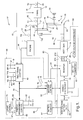
- a control section of the system is generally labeled 46 in the figure, while an electrical power section is generally labeled 86.
- a vehicle drivetrain includes a conventional internal combustion engine 11, electric propulsion motor/generator 14 (hereafter electric machine) and multiple speed ratio transmission 13. Transmission is adapted to receive input torque at input member and transmit output torque to an output shaft 39 through one or more fluid operated friction devices (not shown) which are applied or released in accordance with a predetermined schedule for establishing a desired transmission speed ratio.
- a gear set generally labeled 10 in the figure operatively couples the internal combustion engine output shaft, the electric machine rotor shaft, and transmission input member.
- the gear set 10 in the present embodiment is a compound planetary gear set having a common connecting gear 16 serving as a ring gear in one planetary gear set 19 and as a sun gear in a second planetary gear set 21.
- the sun gear 24 is permanently connected to the rotor shaft as represented by line 29.
- the carrier 23 for a respective first plurality of planetary gears (not shown) of gear set 19 is coupled through one way device 32 to ground 30.
- the radially inner surface of connecting gear 16 has a plurality of teeth 18 comprising the ring gear of gear set 19.
- the first plurality of planetary gears of course, meshingly engage the sun gear 24 and teeth 18 of connecting gear 16.
- connecting gear 16 also has a plurality of teeth 20 allowing it to serve as the sun gear of gear set 21.
- a ring gear 18 is permanently coupled to the output shaft of internal combustion engine 11 as represented by line 27.
- Carrier 26 is connected to a second plurality of planetary gears (not show) of the second gear set 21 and is selectively connectable to the rotor of electric machine 14 through a friction device, hereafter clutch C R .
- the carrier 26 is also selectively connectable to the ring gear 28 of the second planetary gear set 21 through a friction device , hereafter clutch C E .
- the second plurality of planetary gears of course, meshingly engage the teeth 20 of connecting gear 16 and the ring gear 28.
- the carrier 26 is also permanently coupled to the transmission input member as represented by line 37.
- a more detailed description of such an exemplary compound gear set 10 may be found in United States Patent Number 5,285,111 also assigned to the assignee hereof.
- An oil pump (not shown) provides hydraulic fluid under pressure for lubrication and cooling, and also for actuation of clutches C R and C E in a conventional manner.
- the engine output member drives a mechanical oil pump for providing the transmission 13 and gear set 10 with working fluid pressure.
- Such hydraulic systems are well known to those skilled in the art.
- Each clutch C R and C E has associated therewith a respective control chamber in which the fluid pressure is controlled by a respective fluid control valve.
- the fluid control valve is preferably a pulse width modulated solenoid valve.
- Such clutch control hardware is also well known to those skilled in the art.
- Engine 11 includes a conventional throttle mechanism (not shown) connected to an accelerator pedal (not shown) for regulating the air intake of the engine.
- the engine is fueled by a conventional method in relation to the air intake to produce output torque at the output member in proportion thereto.
- the general control section thereof comprises engine and transmission controller 40 for providing conventional engine control functions and transmission control functions, electric machine controller 50 for providing motoring torque and regenerative torque control, and energy management controller 60 for providing control and coordination of gear set 10 clutches and motoring and regenerative torque.
- Brake controller 75 provides for control and monitoring of hydraulic vehicle brakes (not illustrated) including individual wheel speed sensing and hydraulic actuated anti-lock functions. Additionally, the brake controller functions to request regenerative braking vis-a-vis controlled generator torque. All controllers listed are microcomputer based constructed from such conventional elements as microprocessors, memory including ROM and RAM, I/O including A/D and D/A, ALU, and high speed clocks, and are suited for the particular control functions which they individually and cooperatively perform.
- Bi-directional serial data link 70 provides for communication between the various controllers 40,60, and 50.
- the brake controller 75 communicates only with and through energy management controller 60 via dedicated lines represented in the aggregate by line 65 for fast data transfer required for cooperative hydraulic/regenerative brake control.
- Engine control functions carried out in response to various sensed engine operating parameters such as air ingestion, coolant temperature and exhaust gas constituents include engine spark timing control, idle speed control, fuel control, etc., which are effected in accordance with various control signals.
- transmission control functions carried out in response to various sensed transmission operating parameters such as fluid temperature include line pressure regulation and individual clutch apply/release controls, which are effected in accordance with various control signals.
- the various sensed parameters for carrying out the engine and transmission control functions, but not individually utilized by the control of the present invention, as well as the various control signals to the engine and transmission are generally represented in the aggregate by lines 44 and 15 for the engine and transmission, respectively.
- Certain sensed parameters particularly relevant to the present control are illustrated as individual inputs to the engine and transmission controller 40 and include: transmission output speed (No), line 41; engine output speed (Ne), line 43; throttle position (TPS), line 45; service brake switch (BR), line 47; and transmission input shaft speed (Ni), line 49.
- Energy management control functions are carried out in response to various vehicle parameters such as transmission output member speed Ni, electric machine rotor speed Nr, Engine output speed Ne, vehicle speed (Nv), brakes actuation BR, and state of charge and temperature of the battery pack.
- vehicle parameters such as transmission output member speed Ni, electric machine rotor speed Nr, Engine output speed Ne, vehicle speed (Nv), brakes actuation BR, and state of charge and temperature of the battery pack.
- Specific vehicle parameters used by the energy management controller 60 are provided thereto over serial data link 70 from conditioned inputs at the engine and transmission controller 40 and machine controller 50. Additionally, braking data from brake controller 75 is supplied over dedicated data lines as previously mentioned. Battery pack energy requirements are provided by a battery monitor 67 over data line 68.
- Particularly relevant to the control functions performed by the energy management controller 60 in carrying out the present invention are the speed quantities Ni, Ne, No, Nr and Nv, and throttle position TPS.
- Energy management controller 60 provides a torque request over the serial data link 70 to the machine controller 50 for execution thereby.
- Lines 61 and 63 provide pulse width modulated control signals to respective solenoid controlled fluid valves (not shown) to thereby provide controlled fluid pressure to control chambers of clutches C R and C E , respectively, of gear set 10.
- Machine controller 50 is essentially a slave unit to operational requests from energy management controller 60 over serial data link 70.
- a separate input for transmission input member speed Ni on line 49 provides real time data for the machine controller 50 for back-up energy management functions in the event that energy management controller 60 control is somehow displaced.
- electric machine rotor speed Nr on line 48 is input to the controller as is a electric machine temperature signal on line 83.
- Machine controller is interfaced with inverter 80 for supplying thereto the desired inverter operation to effectuate the desired electric machine operation. At least one of the plurality of stator phase currents is sensed to provide data to machine controller 50. Current sense and inverter control signals are represented by line 81 in the figure.
- Operational requests over the serial data link 70 encompass, essentially, torque magnitude and direction and hereafter may be symbolized by the shorthand designation Tq.
- Machine controller preferably operates by processing the request in accordance with real time electric machine speed data Nr to control torque influencing electric machine parameters.
- controlled parameters may include stator field current, slip speed and direction.
- Machine controller preferably derives desired control signals in the form of pulse width modulated gating signals for application to inverter 80 to generate the desired field waveforms through table look-ups of pre-stored data.
- An exemplary control is described in U.S. Patent No. 4,883,973 also assigned to the assignee of the present invention.
- electric machine 14 receives stator phase motoring currents and provides stator phase generating currents through inverter 80 over lines 87a, 87b, and 87c.
- Inverter 80 is coupled to a high voltage battery pack 69 through a power disconnect device 77 and bi-directional high voltage bus lines 71 and 79.
- Device 77 is monitored by and is responsive to machine controller 50 to prevent undesirable overcurrent conditions.
- DC to DC converter 85 is also connected through disconnect device 77 to battery pack 69 and provides a low voltage power source, for example 12 volt, to a system bus 89 for operating conventional vehicle electrical loads (not shown).
- Battery pack is monitored as shown by line 73 for such parameters as temperature, voltage and current draw therefrom or supply thereto by battery monitor 67 for determination of state of charge and undesirable thermal conditions.
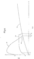
- a graphical representation of the rotor speed Nr, engine output speed Ne and transmission input speed Ni illustrates an exemplary regenerative vehicle launch performed in accordance with the control of the present invention.
- the vertical axis in the figure represents RPM of the various plotted rotational speeds and the horizontal axis in the figure represent time progression relative to a some time t 0 whereat the transmission input speed Ni is substantially zero and hence vehicle speed is substantially zero.
- Changes in the transmission input speed Ni produce proportional changes in transmission output member speed No and, ultimately, vehicle speed Nv.
- This initial condition of vehicle standstill in effect defines a condition precedent of vehicle launch.
- both clutches C R and C E are in a fully released state thereby transmitting no torque thereacross either clutch.
- the transmission output member Upon initiation of the regenerative vehicle launch, the transmission output member is no longer absolutely grounded by virtue of the service brakes, however, some reaction torque is provided at the transmission input member by the road load and inertia torque of the transmission elements.
- the vehicle operator steps into the throttle and internal combustion engine speed increases. Internal combustion engine torque is split in accelerating the rotor and the transmission input member as shown between t 0 + and t 1 of the figure.
- the rotor inertia and generator torques provide the reaction torque to the gear set to accelerate the transmission input member and the road load and inertia torque of the transmission provide the reaction torque for acceleration of the rotor.
- generator torque is increased as a predetermined function of selected vehicle operating parameters thereby providing an increased controlled reaction torque thereat further impeding its rotation and resulting in increased net torque at the transmission input member.
- Transmission input member speed Ni continues thereafter to increase while the rotor speed Nr is pulled down by the controlled generator torque load.
- the speed differential between the rotor and transmission input member has been reduced to a predetermined amount whereat clutch C R is engaged to couple the transmission input member and rotor.
- such coupling through fully applied clutch C R is complete and gear set reaction is through carrier 23 and one way device 32 to ground 30.
- the engine speed output member speed Ne is converged with the transmission input member and rotor speeds by application of clutch C E , thereby providing a 1:1 speed coupling between the engine output, transmission input and rotor and completing the vehicle launch.
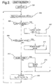
- FIG. 2 a set of flow charts generally illustrative of program steps executed by the energy management controller 60 illustrated in figure 1 are set forth.
- the flow chart of figure 2 represents a set of instructions in a main or executive energy management control loop (EMC ROUTINE) for performing certain repetitive functions including data acquisition and conditioning, system diagnostics and energy management mode selection.
- the flow chart of figure 3 represents a set of instructions in a LAUNCH MODE routine setting forth a preferred embodiment of the regenerative launch control of the present invention.
- blocks 201 of the EMC ROUTINE steps are executed to initialize various counters, flags, registers etc. such as when the vehicle is first powered up. Such initialization steps are thereafter bypassed in the main loop of the EMC ROUTINE.
- block 203 represents steps for reading in (and conditioning where necessary) the various data from brake controller, battery monitor, and serial data link used in the energy management control modes. Particularly with respect to the LAUNCH MODE requirements, such data includes: rotor speed, Nr; transmission input speed, Ni; transmission output speed, No; engine output speed, Ne; vehicle speed, Nv and, percent throttle, %T.
- Blocks 205, 209 and 213 represent program steps for determination of the particular energy management mode in effect from among modes including a launch mode (block 207), a power assist mode (block 211), and a regenerative mode (block 215). Affirmative answers to predetermined mode specific entry conditions represented by blocks 205, 209 and 213 for the launch, power assist and regenerative modes, respectively, results in the execution of steps associated with the particular mode to be invoked or in effect.
- the launch mode will be treated in detail with respect to the flow diagram of figure 3; however, it suffices for purpose of this disclosure to say that the power assist mode generally invokes control during positive wheel torque application by contributing motoring torque to the engine torque or extracting generator torque therefrom, and regenerative mode generally invokes control during negative wheel torque conditions such as vehicle coast down and service brake application.
- block 220 represents steps for output of clutch duty cycle signals for the clutch control valves controlling clutches C E and C R , and the requested torque signal Tq for implementation by the machine controller.
- block 205 With respect to the launch mode entry conditions, block 205 requires, for example, that vehicle speed Nv be below 1 MPH and throttle position %T be above 2% in the present preferred implementation. If these exemplary conditions are not met, block 205 is answered negatively and blocks 209-215 determine an appropriate energy management mode. proceeding with the assumption that the conditions are met, block 205 is answered affirmatively and the LAUNCH MODE routine is executed.
- block 301 represents the execution of program instructions for calculating the speed differential ⁇ N between the rotor speed Nr and the transmission input member speed Ni. ⁇ N will be utilized later in the routine to determine which one of an open loop torque control or closed loop speed control techniques will be implemented.
- Blocks 303 through 305 represent engine overspeed protection steps, the objective of which is to bring impending excessive engine speed down.
- Block 303 performs a check of engine speed against a calibrated threshold value K1 which if exceeded passes processing to the steps of block 305.
- Block 305 would then check vehicle speed against a calibrated threshold K2 which if exceeded causes execution of the steps represented by block 309. This being the case, full application of both clutches is indicated by setting the respective duty cycle commands C E DC and C R DC to 100% at block 309. These events effectively close out the regenerative launch mode.
- the steps represented by block 311 determine whether the speed differential ⁇ N between the rotor speed Nr and the transmission input member speed Ni is within a predetermined range such that closed loop speed control may be invoked. For example, if ⁇ N is less than 200 rpm and greater than -500 rpm, then closed loop speed control as embodied in blocks 313-337 is invoked. However, if ⁇ N is outside of this predetermined range, open loop torque control is executed as embodied in blocks 325-329. Objectively, the closed loop speed control is performed to support the rotor speed while application if the clutch CR is invoked lest the rotor speed undershoot the transmission input shaft member speed.
- Block 327 next represents a resetting of the clutch apply timer CTMR to refresh the timer upon any initial invocation, and consequent release of the clutches, of the open loop torque control.
- block 329 represents instructions executed in the determination of a torque command Tq for the motor.
- these steps carry out a table look-up of torque values in accordance with a predetermined set of independent variables. In the present exemplary embodiment, it is preferred to reference a two-dimensional table by the combination of engine speed Ne and transmission input member speed Ni.
- the routine then returns to the main loop where the control outputs are generated as shown in block 220.
- block 311 recognizes that the speed differential ⁇ N is such that closed loop speed control is desired (i.e. between the upper and lower speed differential limits K4 and K5, respectively)
- the steps of blocks 313-337 are executed to converge the rotor speed Nr and the engine speed Ne to the transmission input member speed Ni.
- clutch apply timer CTMR is checked to determine whether it has expired or timed out, thereby indicating the end of the closed loop control and likewise the end of the launch mode.
- CTMR has been incremented to a predetermined value K3 then it is deemed expired.
- block 314 executes steps to set the clutch C E duty cycle to full apply or 100%. Having previously been set to a full apply duty cycle (block 333), clutch C R is also commanded on fully. Processing returns to the main loop where the control outputs are generated as shown in block 220.
- Determination that CTMR has not yet expired passes control to block 315 whereat a vehicle speed Nv is checked against a calibrated upper vehicle speed threshold K6 to determine with certainty whether to application of the clutches C E and C R is in order.
- the upper vehicle speed threshold K6 ensures that the engine speed after application of clutch C R will remain at or above an acceptable level.
- blocks 319-335 are executed to determine appropriate clutch pressures and duty cycles for achieving same.
- Block 319 determines from clutch apply timer CTMR if initial values for clutch C E pressure (PC E ) and pressure rate increase (Pi) need be determined. Upon an initial pass, CTMR has not been updated from the initial value of zero so block 323 is executed.
- Steps at block 323 determine the initial pressure quantities PC E and Pi preferably as shown as a single dimensional table look-up as a function of the present throttle position (%T). Throttle position is conventionally utilized as a load or torque indicating parameter in the control of automatic transmissions. It is used similarly in the present invention as a measure of engine torque which is to be transferred through the clutch C E . Additionally, and also as a function of %T, expiration value K3 for the clutch apply timer expiration is determined. All determinations in block 323 are provided by way of look-up tables, preferably.
- PC E as determined at block 323 is the initial apply pressure for the clutch C E
- Pi is the incremental pressure repetitively added thereto to ramp the net apply pressure upward.
- the expiration value K3 is preferably reduced as %T increases. The shorter apply times (K3) as %T increases comports with the larger incremental pressures Pi as %T increases.
- Block 333 would next set the duty cycle of the clutch CE to correspond to the desired pressure PC E which on the initial pass is the initial pressure determined as a function of %T. From there, CTMR is incremented at block 335.
- block 321 updates the clutch PCE pressure by summing therewith the predetermined incremental pressure Pi. Blocks 333 and 335 are thereafter executed as previously described.
- a lower vehicle speed threshold K7 is compared to the vehicle speed Nv at block 317.
- the clutch apply timer has not expired (block 313) and vehicle speed does not exceed the upper threshold K6.
- the closed loop speed control is exited in favor of the open loop torque control (blocks 325-329).
- the lower vehicle speed threshold K7 enables the release of the clutches thereby allowing the engine speed to increase if necessary to accommodate the conditions which reduced the vehicle speed (e.g. grade load).
- the difference between the upper and lower vehicle speed thresholds provides for a degree of hysteresis whereby hunting between the closed loop speed control and open loop torque control might otherwise occur.
- block 331 checks the clutch apply timer CTMR to determine if the clutches CE and CR are being applied. A non-zero value of CTMR indicates that they are being applied and block 321 is executed to update the pressure of the clutch PC E as earlier mentioned. From there, blocks 333 and 335 provide the duty cycle values and increment the clutch apply timer CTMR. An un-incremented CTMR determined at block 331 bypasses blocks 321, 333 and 335
- Block 337 is executed from one of block 335 or 331 to effectuate the speed control desired.
- Block 337 represent steps to develop the torque signal Tq intended to converge the rotor speed Nr and transmission input member speed Ni. This is accomplished by conventional proportional/integral/derivative control tracking a single reference. In this case, the speed error ⁇ N is used to control the rotor speed Nr to the transmission input member speed Ni.
Landscapes
- Engineering & Computer Science (AREA)
- Transportation (AREA)
- Mechanical Engineering (AREA)
- Chemical & Material Sciences (AREA)
- Combustion & Propulsion (AREA)
- Power Engineering (AREA)
- Automation & Control Theory (AREA)
- Control Of Driving Devices And Active Controlling Of Vehicle (AREA)
- Electric Propulsion And Braking For Vehicles (AREA)
- Hybrid Electric Vehicles (AREA)
- Arrangement Of Transmissions (AREA)
Claims (4)
- Verfahren zum Anfahren eines Fahrzeuges aus einem im wesentlichen statischen Zustand, wobei das Fahrzeug einen Antriebsstrang aufweist, umfassend einen Verbrennungsmotor (11) mit einem Motorabtriebselement (28), eine Elektromaschine (14) mit einem Rotor und einen Zahnradsatz (10), der im Betrieb den Verbrennungsmotorabtrieb, den Rotor und das Zahnradsatzabtriebselement (26) des Zahnradsatzes koppelt, wobei das Zahnradsatzabtriebselement im Betrieb an mindestens ein Antriebsrad zum Antreiben des Fahrzeuges gekoppelt ist, eine erste selektiv in Eingriff bringbare Reibeinrichtung (CE) zum direkten Koppeln des Zahnradsatzabtriebselements mit dem Motorabtriebselement (28) und eine zweite selektiv in Eingriff bringbare Reibeinrichtung (CR) zum direkten Koppeln des Zahnradsatzabtriebselements (26) mit dem Rotor aufweist, wobei die Elektromaschine (14) als ein elektrisches Bremsenreaktionselement wirkt, um die Drehmomentübertragung zwischen dem Motorabtriebselement und dem Zahnradsatzabtriebselement zu steuern, wobei das Verfahren umfaßt, daß ein vorbestimmter Satz von Betriebsparametern des Fahrzeugantriebsstrangs (203) detektiert wird, ein das Drehmoment beeinflussender Elektromaschinenparameter zum Aufbringen einer Generatordrehmomentgröße auf den Rotor als eine Funktion des vorbestimmten Satzes von Fahrzeugbetriebsparametern gesteuert wird, wodurch jeweilige Drehzahlen des Rotors und des Zahnradsatzabtriebselements sich aneinander annähern gelassen werden (325-329), und, wenn die Drehzahlen des Rotors und des Zahnradsatzabtriebselements eine vorbestimmte Drehzahldifferenzbeziehung erzielen (311), die Rotordrehzahl auf die Drehzahl des Zahnradsatzabtriebselements gesteuert wird (337), dadurch gekennzeichnet, daß:der Schritt des Steuerns des das Drehmoment beeinflussenden Parameters der Elektromaschine durchgeführt wird, indem eine Steuerung mit offenem Regelkreis (329) des das Drehmoment beeinflussenden Parameters der Elektromaschine durchgeführt wird,der Schritt des Steuerns der Rotordrehzahl auf die Drehzahl des Zahnradsatzabtriebselements durchgeführt wird, indem eine Steuerung mit geschlossenem Regelkreis der Rotordrehzahl durchgeführt wird, undwenn die Fahrzeuggeschwindigkeit eine vorbestimmte Schwelle überschreitet (315), die zweite Reibeinrichtung (CR; 333) vollständig in Eingriff gebracht wird, und die erste Reibeinrichtung (CE) fortschreitend von einem Anfangseingriffsdruck zu einem Endeingriffsdruck in Eingriff gebracht wird (321), wobei die Anfangs- und Endeingriffsdrücke als eine Funktion eines vorbestimmten Maßes des Motordrehmoments bestimmt werden (323).
- Verfahren zum Anfahren eines Fahrzeuges aus einem im wesentlichen statischen Zustand nach Anspruch 1, wobei der vorbestimmte Satz von Betriebsparametern des Fahrzeugantriebsstrangs die Drehzahl des Motorabtriebselements (NE), die Rotordrehzahl (Nr) und die Drehzahl des Zahnradsatzabtriebselements (Ni) umfaßt.
- Verfahren zum Anfahren eines Fahrzeuges aus einem im wesentlichen statischen Zustand nach Anspruch 1, wobei der das Drehmoment beeinflussende Parameter der Elektromaschine den Statorstrom umfaßt.
- Verfahren zum Anfahren eines Fahrzeuges aus einem im wesentlichen statischen Zustand nach Anspruch 1, wobei der das Drehmoment beeinflussende Parameter der Elektromaschine die Schlupfgeschwindigkeit der Elektromaschine umfaßt.
Applications Claiming Priority (2)
| Application Number | Priority Date | Filing Date | Title |
|---|---|---|---|
| US08/573,685 US5637987A (en) | 1995-12-18 | 1995-12-18 | Regenerative vehicle launch |
| US573685 | 1995-12-18 |
Publications (3)
| Publication Number | Publication Date |
|---|---|
| EP0780256A2 EP0780256A2 (de) | 1997-06-25 |
| EP0780256A3 EP0780256A3 (de) | 1999-01-07 |
| EP0780256B1 true EP0780256B1 (de) | 2001-02-07 |
Family
ID=24292999
Family Applications (1)
| Application Number | Title | Priority Date | Filing Date |
|---|---|---|---|
| EP96203167A Expired - Lifetime EP0780256B1 (de) | 1995-12-18 | 1996-11-13 | Verfahren zum Anfahren mit Energierückgewinnung für Hybridfahrzeug |
Country Status (4)
| Country | Link |
|---|---|
| US (1) | US5637987A (de) |
| EP (1) | EP0780256B1 (de) |
| JP (1) | JPH09191504A (de) |
| DE (1) | DE69611752T2 (de) |
Families Citing this family (78)
| Publication number | Priority date | Publication date | Assignee | Title |
|---|---|---|---|---|
| JP3099699B2 (ja) * | 1995-05-19 | 2000-10-16 | トヨタ自動車株式会社 | 動力伝達装置及びその制御方法 |
| JP3063589B2 (ja) * | 1995-05-19 | 2000-07-12 | トヨタ自動車株式会社 | 動力伝達装置およびその制御方法 |
| JP3052803B2 (ja) * | 1995-05-19 | 2000-06-19 | トヨタ自動車株式会社 | 動力伝達装置およびその制御方法 |
| JP3099698B2 (ja) * | 1995-05-19 | 2000-10-16 | トヨタ自動車株式会社 | 動力伝達装置及びその制御方法 |
| JP3052802B2 (ja) * | 1995-05-19 | 2000-06-19 | トヨタ自動車株式会社 | 動力伝達装置及びその制御方法 |
| JP3409523B2 (ja) * | 1995-08-02 | 2003-05-26 | アイシン・エィ・ダブリュ株式会社 | 車両用駆動装置の制御装置 |
| JPH09277847A (ja) * | 1996-04-11 | 1997-10-28 | Toyota Motor Corp | ハイブリッド車両のエンジンブレーキ制御装置 |
| JP2843883B2 (ja) * | 1996-05-22 | 1999-01-06 | 本田技研工業株式会社 | ハイブリッド車両の制御装置 |
| FR2752778B1 (fr) * | 1996-08-27 | 1998-10-09 | Smh Management Services Ag | Groupe de traction tandem a reducteurs et vehicule a traction electrique ou hybride comportant un tel groupe |
| JP3050138B2 (ja) | 1996-09-13 | 2000-06-12 | トヨタ自動車株式会社 | 動力出力装置およびその制御方法 |
| JP3354074B2 (ja) * | 1997-04-25 | 2002-12-09 | ジヤトコ株式会社 | パラレルハイブリッド車両の制御装置 |
| US5903116A (en) * | 1997-09-08 | 1999-05-11 | Capstone Turbine Corporation | Turbogenerator/motor controller |
| US6487096B1 (en) | 1997-09-08 | 2002-11-26 | Capstone Turbine Corporation | Power controller |
| US6784565B2 (en) | 1997-09-08 | 2004-08-31 | Capstone Turbine Corporation | Turbogenerator with electrical brake |
| US6124645A (en) | 1997-11-21 | 2000-09-26 | Lockheed Martin Corporation | Electric motor rotor holding arrangement |
| CA2312752C (en) | 1997-12-05 | 2003-07-08 | Toyota Jidosha Kabushiki Kaisha | Hybrid drive system |
| US6870279B2 (en) * | 1998-01-05 | 2005-03-22 | Capstone Turbine Corporation | Method and system for control of turbogenerator power and temperature |
| US6033042A (en) * | 1998-03-03 | 2000-03-07 | General Motors Corporation | Vehicle brake system with powertrain dynamic braking |
| US20040135436A1 (en) * | 1998-04-02 | 2004-07-15 | Gilbreth Mark G | Power controller system and method |
| US20040119291A1 (en) * | 1998-04-02 | 2004-06-24 | Capstone Turbine Corporation | Method and apparatus for indirect catalytic combustor preheating |
| US6118202A (en) * | 1998-05-11 | 2000-09-12 | Active Power, Inc. | High-efficiency inductor-alternator |
| FR2782958B1 (fr) | 1998-09-05 | 2005-11-04 | Mannesmann Sachs Ag | Systeme d'entrainement pour vehicule automobile avec moteur a combustion interne et moteur electrique |
| US6338391B1 (en) | 1999-03-01 | 2002-01-15 | Paice Corporation | Hybrid vehicles incorporating turbochargers |
| US6209672B1 (en) | 1998-09-14 | 2001-04-03 | Paice Corporation | Hybrid vehicle |
| US6554088B2 (en) | 1998-09-14 | 2003-04-29 | Paice Corporation | Hybrid vehicles |
| US6612112B2 (en) | 1998-12-08 | 2003-09-02 | Capstone Turbine Corporation | Transient turbine exhaust temperature control for a turbogenerator |
| US6364434B1 (en) * | 1999-04-01 | 2002-04-02 | Daimlerchrysler Corporation | Intelligent coast-down algorithm for electric vehicle |
| US6362536B1 (en) * | 1999-08-10 | 2002-03-26 | Honda Giken Kogyo Kabushiki Kaisha | Apparatus and method for controlling power generation for hybrid vehicle |
| JP3967043B2 (ja) * | 1999-09-02 | 2007-08-29 | 日産自動車株式会社 | ハイブリッド車両の制御装置 |
| US6376927B1 (en) | 2000-01-18 | 2002-04-23 | Saturn Corporation | Hybrid electric drive and control method therefor |
| US6254507B1 (en) | 2000-01-18 | 2001-07-03 | General Motors Corporation | Reverse one-way torque converter clutch |
| TW459663U (en) * | 2000-10-13 | 2001-10-11 | Nat Science Council | Hybrid electric system |
| US6787933B2 (en) * | 2001-01-10 | 2004-09-07 | Capstone Turbine Corporation | Power generation system having transient ride-through/load-leveling capabilities |
| US6812586B2 (en) * | 2001-01-30 | 2004-11-02 | Capstone Turbine Corporation | Distributed power system |
| US6455947B1 (en) | 2001-02-14 | 2002-09-24 | Bae Systems Controls, Inc. | Power combining apparatus for hybrid electric vehicle |
| US20040090195A1 (en) * | 2001-06-11 | 2004-05-13 | Motsenbocker Marvin A. | Efficient control, monitoring and energy devices for vehicles such as watercraft |
| US6909200B2 (en) * | 2002-02-28 | 2005-06-21 | Azure Dynamics Inc. | Methods of supplying energy to an energy bus in a hybrid electric vehicle, and apparatuses, media and signals for the same |
| US7021410B2 (en) | 2002-11-27 | 2006-04-04 | Eaton Corporation | Method and system for determining the torque required to launch a vehicle having a hybrid drive-train |
| US20040148942A1 (en) * | 2003-01-31 | 2004-08-05 | Capstone Turbine Corporation | Method for catalytic combustion in a gas- turbine engine, and applications thereof |
| US6991053B2 (en) * | 2003-02-27 | 2006-01-31 | Ford Global Technologies, Llc | Closed-loop power control for hybrid electric vehicles |
| US7219000B2 (en) * | 2003-10-14 | 2007-05-15 | General Motors Corporation | Speed control for an electrically variable transmission |
| US7082850B2 (en) * | 2003-12-30 | 2006-08-01 | Eaton Corporation | Hybrid powertrain system |
| US7081725B2 (en) * | 2004-02-06 | 2006-07-25 | Visteon Global Technologies, Inc. | Power electronics apparatuses for double-fed induction generator to induction motor drive system |
| US7285869B2 (en) * | 2004-07-29 | 2007-10-23 | Ford Global Technologies, Llc | Method for estimating engine power in a hybrid electric vehicle powertrain |
| US7196493B2 (en) * | 2004-07-30 | 2007-03-27 | Ford Global Technologies, Llc | Closed loop control of battery power limits based on voltage |
| FR2875183B1 (fr) * | 2004-09-15 | 2008-02-15 | Peugeot Citroen Automobiles Sa | Dispositif de transmission de puissance pour vehicule automobile et procede d'utilisation de ce dispositif |
| US7335123B2 (en) * | 2004-11-12 | 2008-02-26 | Eaton Corporation | Hybrid powertrain system and transformer module |
| EP1666321A1 (de) * | 2004-12-06 | 2006-06-07 | Ford Global Technologies, LLC, A subsidary of Ford Motor Company | Verfahren zum Bremsen eines Fahrzeugs, Bremsvorrichtung und Fahrzeug mit einer Bremsvorrichtung |
| US7600595B2 (en) * | 2005-03-14 | 2009-10-13 | Zero Emission Systems, Inc. | Electric traction |
| US7543454B2 (en) | 2005-03-14 | 2009-06-09 | Zero Emission Systems, Inc. | Method and auxiliary system for operating a comfort subsystem for a vehicle |
| US7617893B2 (en) * | 2005-08-02 | 2009-11-17 | Ford Global Technologies, Llc | Method and system for determining final desired wheel power in a hybrid electric vehicle powertrain |
| US7992948B2 (en) | 2005-12-07 | 2011-08-09 | The Regents Of The University Of Michigan | Hydraulic regenerative braking for a vehicle |
| DE102006006107A1 (de) * | 2006-02-10 | 2007-08-16 | Robert Bosch Gmbh | Verfahren zum Betreiben einer Antriebsvorrichtung eines Hybridfahrzeugs |
| US7921945B2 (en) * | 2006-02-21 | 2011-04-12 | Clean Emissions Technologies, Inc. | Vehicular switching, including switching traction modes and shifting gears while in electric traction mode |
| US8565969B2 (en) | 2007-04-03 | 2013-10-22 | Clean Emissions Technologies, Inc. | Over the road/traction/cabin comfort retrofit |
| US20070284164A1 (en) * | 2006-05-19 | 2007-12-13 | Net Gain Technologies | Motor vehicle with electric boost motor |
| US7537542B2 (en) * | 2006-09-11 | 2009-05-26 | Gm Global Technology Operations, Inc. | Control system architecture for a hybrid powertrain |
| US8235853B2 (en) | 2006-10-18 | 2012-08-07 | Magna Powertrain Inc. | Hybrid transmissions with planetary gearsets |
| US7921950B2 (en) * | 2006-11-10 | 2011-04-12 | Clean Emissions Technologies, Inc. | Electric traction retrofit |
| DE102007015875A1 (de) * | 2007-04-02 | 2008-10-09 | Robert Bosch Gmbh | Verfahren zum Betreiben eines Hybridantriebes eines Fahrzeugs |
| EP2072320A1 (de) | 2007-12-18 | 2009-06-24 | Nederlandse Organisatie voor toegepast- natuurwetenschappelijk onderzoek TNO | Verfahren für den Betrieb eines elektromechanischen Wandlers, Steuerung und Computerprogramm |
| JP2011520675A (ja) | 2008-03-19 | 2011-07-21 | ゼロ・エミッション・システムズ・インコーポレーテッド | 電気式トラクションシステムおよび方法 |
| US9758146B2 (en) | 2008-04-01 | 2017-09-12 | Clean Emissions Technologies, Inc. | Dual mode clutch pedal for vehicle |
| WO2010024737A1 (en) * | 2008-08-29 | 2010-03-04 | Volvo Lastavagnar Ab | Transmission control system in vehicles |
| US8215282B2 (en) * | 2008-10-23 | 2012-07-10 | GM Global Technology Operations LLC | Method and system to reduce accessory drive belt slip |
| US8622859B2 (en) | 2009-06-10 | 2014-01-07 | Czero Holding Company, Llc | Systems and methods for hybridization of a motor vehicle using hydraulic components |
| DE102009029036B4 (de) * | 2009-08-31 | 2018-05-03 | Zf Friedrichshafen Ag | Verfahren zum Betreiben eines Antriebstrangs |
| US9631528B2 (en) | 2009-09-03 | 2017-04-25 | Clean Emissions Technologies, Inc. | Vehicle reduced emission deployment |
| WO2012114902A1 (ja) * | 2011-02-25 | 2012-08-30 | Ntn株式会社 | 電気自動車 |
| US8905167B2 (en) | 2011-07-29 | 2014-12-09 | Chrysler Group Llc | Engine start control system for an electrically variable transmission |
| CN104373222B (zh) * | 2013-08-16 | 2017-06-23 | 上海汽车集团股份有限公司 | 基于进气量对汽车发动机和发电机的控制策略 |
| US10059189B2 (en) | 2014-04-29 | 2018-08-28 | Cummins Inc. | Electric machine with variable torque drive |
| US10703215B2 (en) * | 2014-10-20 | 2020-07-07 | Ford Global Technologies, Llc | Hybrid powertrain speed control |
| US20160137047A1 (en) * | 2014-11-17 | 2016-05-19 | Lg Electronics Inc. | Driving apparatus of vehicle |
| JP6455499B2 (ja) * | 2016-11-25 | 2019-01-23 | トヨタ自動車株式会社 | 車両制御装置 |
| JP6635066B2 (ja) * | 2017-02-06 | 2020-01-22 | トヨタ自動車株式会社 | ハイブリッド車両 |
| JP6897512B2 (ja) * | 2017-11-13 | 2021-06-30 | トヨタ自動車株式会社 | ハイブリッド車両の駆動力制御装置 |
| CN111137137A (zh) * | 2018-11-05 | 2020-05-12 | 宝沃汽车(中国)有限公司 | 混合动力汽车的控制方法、系统及混合动力汽车 |
Family Cites Families (11)
| Publication number | Priority date | Publication date | Assignee | Title |
|---|---|---|---|---|
| US4883973A (en) * | 1988-08-01 | 1989-11-28 | General Motors Corporation | Automotive electrical system having a starter/generator induction machine |
| US5496227A (en) * | 1990-04-18 | 1996-03-05 | Hitachi, Ltd. | Torque control method and apparatus for internal combustion engine and motor vehicles employing the same |
| US5258651A (en) * | 1992-04-17 | 1993-11-02 | General Motors Corporation | Electrically biased starting reaction device for a power transmission |
| JP2857535B2 (ja) * | 1992-05-19 | 1999-02-17 | 株式会社エクォス・リサーチ | ハイブリッド型車両 |
| JP3221118B2 (ja) * | 1992-11-27 | 2001-10-22 | 株式会社エクォス・リサーチ | ハイブリット車輌における動力伝達装置 |
| US5285111A (en) * | 1993-04-27 | 1994-02-08 | General Motors Corporation | Integrated hybrid transmission with inertia assisted launch |
| US5558173A (en) * | 1993-09-23 | 1996-09-24 | General Motors Corporation | Integrated hybrid transmission with mechanical accessory drive |
| US5558175A (en) * | 1994-12-13 | 1996-09-24 | General Motors Corporation | Hybrid power transmission |
| US5558595A (en) * | 1995-02-17 | 1996-09-24 | General Motors Corporation | One-mode, input-split, parallel, hybrid transmission |
| US5558589A (en) * | 1995-07-20 | 1996-09-24 | General Motors Corporation | Two-mode, compound-split, electro-mechanical vehicular transmission |
| US5571058A (en) * | 1995-08-08 | 1996-11-05 | General Motors Corporation | Four-mode, input-split, paralell, hybrid transmission |
-
1995
- 1995-12-18 US US08/573,685 patent/US5637987A/en not_active Expired - Lifetime
-
1996
- 1996-11-13 DE DE69611752T patent/DE69611752T2/de not_active Expired - Fee Related
- 1996-11-13 EP EP96203167A patent/EP0780256B1/de not_active Expired - Lifetime
- 1996-12-18 JP JP33804996A patent/JPH09191504A/ja active Pending
Also Published As
| Publication number | Publication date |
|---|---|
| US5637987A (en) | 1997-06-10 |
| EP0780256A2 (de) | 1997-06-25 |
| DE69611752D1 (de) | 2001-03-15 |
| DE69611752T2 (de) | 2001-05-23 |
| EP0780256A3 (de) | 1999-01-07 |
| JPH09191504A (ja) | 1997-07-22 |
Similar Documents
| Publication | Publication Date | Title |
|---|---|---|
| EP0780256B1 (de) | Verfahren zum Anfahren mit Energierückgewinnung für Hybridfahrzeug | |
| US6902512B2 (en) | Power output apparatus and movable body with power output apparatus mounted thereon | |
| US9630626B2 (en) | System and method for managing hybrid vehicle regenerative braking | |
| US5289890A (en) | Drive unit for electric motor vehicle | |
| US6976388B2 (en) | Diagnostic method for a torque control of an electrically variable transmission | |
| US7634344B2 (en) | Driving force control apparatus for automotive vehicles | |
| US6931318B2 (en) | Hybrid vehicle and method of starting internal combustion engine mounted on hybrid vehicle | |
| US7975791B2 (en) | Hybrid vehicle drive control system | |
| EP1013973B1 (de) | Unabhängige Steuerung von Dauerbremsen auf Getriebeseite und Motorseite während des gangschaltens | |
| CN100458235C (zh) | 驱动系统、包括该驱动系统的动力输出系统、配备该动力输出系统的车辆、及驱动系统控制方法 | |
| US6394208B1 (en) | Starter/alternator control strategy to enhance driveability of a low storage requirement hybrid electric vehicle | |
| US20130331230A1 (en) | Transmission control during regenerative braking | |
| US20090062063A1 (en) | Vehicle, driving system, and control methods thereof | |
| US9242630B2 (en) | Method and apparatus for controlling a torque converter clutch in a multi-mode powertrain system | |
| US7469169B2 (en) | Method for control of input power distribution in a motor vehicle with hybrid engine drive | |
| US20170327005A1 (en) | Hybrid electric vehicle creep control | |
| US7243011B2 (en) | Hybrid transmission launch algorithm | |
| US10870424B2 (en) | Hybrid vehicle drive system | |
| CN107914699A (zh) | 混合动力电动车辆的控制方法 | |
| US11485347B2 (en) | Drive force control system for vehicle | |
| US6493611B2 (en) | Vehicle controller | |
| US11584359B2 (en) | Control device of hybrid vehicle and control method | |
| KR20070090846A (ko) | 하이브리드 구동 장치의 조절 방법 | |
| EP1323564B1 (de) | Steuerungssystem eines Hybridfahrzeugs | |
| US10479345B2 (en) | Method of decoupling input and output torque for engine speed control and hybrid powertrain utilizing same |
Legal Events
| Date | Code | Title | Description |
|---|---|---|---|
| PUAI | Public reference made under article 153(3) epc to a published international application that has entered the european phase |
Free format text: ORIGINAL CODE: 0009012 |
|
| AK | Designated contracting states |
Kind code of ref document: A2 Designated state(s): DE FR GB |
|
| PUAL | Search report despatched |
Free format text: ORIGINAL CODE: 0009013 |
|
| AK | Designated contracting states |
Kind code of ref document: A3 Designated state(s): DE FR GB |
|
| 17P | Request for examination filed |
Effective date: 19990707 |
|
| 17Q | First examination report despatched |
Effective date: 19990819 |
|
| GRAG | Despatch of communication of intention to grant |
Free format text: ORIGINAL CODE: EPIDOS AGRA |
|
| GRAG | Despatch of communication of intention to grant |
Free format text: ORIGINAL CODE: EPIDOS AGRA |
|
| GRAH | Despatch of communication of intention to grant a patent |
Free format text: ORIGINAL CODE: EPIDOS IGRA |
|
| GRAH | Despatch of communication of intention to grant a patent |
Free format text: ORIGINAL CODE: EPIDOS IGRA |
|
| RAP1 | Party data changed (applicant data changed or rights of an application transferred) |
Owner name: DELPHI TECHNOLOGIES, INC. |
|
| GRAA | (expected) grant |
Free format text: ORIGINAL CODE: 0009210 |
|
| AK | Designated contracting states |
Kind code of ref document: B1 Designated state(s): DE FR GB |
|
| REF | Corresponds to: |
Ref document number: 69611752 Country of ref document: DE Date of ref document: 20010315 |
|
| ET | Fr: translation filed | ||
| PG25 | Lapsed in a contracting state [announced via postgrant information from national office to epo] |
Ref country code: GB Free format text: LAPSE BECAUSE OF NON-PAYMENT OF DUE FEES Effective date: 20011113 |
|
| PLBE | No opposition filed within time limit |
Free format text: ORIGINAL CODE: 0009261 |
|
| STAA | Information on the status of an ep patent application or granted ep patent |
Free format text: STATUS: NO OPPOSITION FILED WITHIN TIME LIMIT |
|
| REG | Reference to a national code |
Ref country code: GB Ref legal event code: IF02 |
|
| 26N | No opposition filed | ||
| PG25 | Lapsed in a contracting state [announced via postgrant information from national office to epo] |
Ref country code: DE Free format text: LAPSE BECAUSE OF NON-PAYMENT OF DUE FEES Effective date: 20020702 |
|
| PG25 | Lapsed in a contracting state [announced via postgrant information from national office to epo] |
Ref country code: FR Free format text: LAPSE BECAUSE OF NON-PAYMENT OF DUE FEES Effective date: 20020730 |
|
| REG | Reference to a national code |
Ref country code: FR Ref legal event code: ST |
|
| REG | Reference to a national code |
Ref country code: FR Ref legal event code: ST |