EP0780250A2 - Fine adjustment of a MacPherson suspension strut: means for adjusting on the strut and measuring bench - Google Patents
Fine adjustment of a MacPherson suspension strut: means for adjusting on the strut and measuring bench Download PDFInfo
- Publication number
- EP0780250A2 EP0780250A2 EP96119526A EP96119526A EP0780250A2 EP 0780250 A2 EP0780250 A2 EP 0780250A2 EP 96119526 A EP96119526 A EP 96119526A EP 96119526 A EP96119526 A EP 96119526A EP 0780250 A2 EP0780250 A2 EP 0780250A2
- Authority
- EP
- European Patent Office
- Prior art keywords
- cup
- axis
- rod
- leg
- spring
- Prior art date
- Legal status (The legal status is an assumption and is not a legal conclusion. Google has not performed a legal analysis and makes no representation as to the accuracy of the status listed.)
- Granted
Links
- 239000000725 suspension Substances 0.000 title claims abstract description 27
- 230000035939 shock Effects 0.000 claims abstract description 46
- 239000006096 absorbing agent Substances 0.000 claims abstract description 43
- 238000013519 translation Methods 0.000 claims description 9
- 230000006835 compression Effects 0.000 claims description 6
- 238000007906 compression Methods 0.000 claims description 6
- 238000000034 method Methods 0.000 claims description 4
- 230000008878 coupling Effects 0.000 claims description 3
- 238000010168 coupling process Methods 0.000 claims description 3
- 238000005859 coupling reaction Methods 0.000 claims description 3
- 125000006850 spacer group Chemical group 0.000 claims description 3
- 239000011248 coating agent Substances 0.000 claims description 2
- 238000000576 coating method Methods 0.000 claims description 2
- 230000003100 immobilizing effect Effects 0.000 claims description 2
- 238000009434 installation Methods 0.000 claims description 2
- 230000002427 irreversible effect Effects 0.000 claims description 2
- KJFBVJALEQWJBS-XUXIUFHCSA-N maribavir Chemical compound CC(C)NC1=NC2=CC(Cl)=C(Cl)C=C2N1[C@H]1O[C@@H](CO)[C@H](O)[C@@H]1O KJFBVJALEQWJBS-XUXIUFHCSA-N 0.000 abstract 1
- 238000005259 measurement Methods 0.000 description 19
- 238000010008 shearing Methods 0.000 description 10
- 238000013461 design Methods 0.000 description 7
- 238000012937 correction Methods 0.000 description 6
- 230000002301 combined effect Effects 0.000 description 5
- 208000031968 Cadaver Diseases 0.000 description 4
- 238000004519 manufacturing process Methods 0.000 description 4
- 230000009471 action Effects 0.000 description 3
- 230000006978 adaptation Effects 0.000 description 3
- 238000006243 chemical reaction Methods 0.000 description 3
- 239000006185 dispersion Substances 0.000 description 3
- 230000000694 effects Effects 0.000 description 3
- 238000012423 maintenance Methods 0.000 description 3
- 238000012986 modification Methods 0.000 description 3
- 230000004048 modification Effects 0.000 description 3
- KWGRBVOPPLSCSI-WPRPVWTQSA-N (-)-ephedrine Chemical compound CN[C@@H](C)[C@H](O)C1=CC=CC=C1 KWGRBVOPPLSCSI-WPRPVWTQSA-N 0.000 description 2
- 230000008901 benefit Effects 0.000 description 2
- 230000008859 change Effects 0.000 description 2
- 238000010276 construction Methods 0.000 description 2
- 238000001514 detection method Methods 0.000 description 2
- 238000001914 filtration Methods 0.000 description 2
- 238000005457 optimization Methods 0.000 description 2
- 238000012545 processing Methods 0.000 description 2
- 230000003542 behavioural effect Effects 0.000 description 1
- 230000000295 complement effect Effects 0.000 description 1
- 238000005520 cutting process Methods 0.000 description 1
- 230000007547 defect Effects 0.000 description 1
- 238000011161 development Methods 0.000 description 1
- 238000006073 displacement reaction Methods 0.000 description 1
- 238000009826 distribution Methods 0.000 description 1
- 210000005069 ears Anatomy 0.000 description 1
- 238000002474 experimental method Methods 0.000 description 1
- 230000007246 mechanism Effects 0.000 description 1
- 239000002184 metal Substances 0.000 description 1
- 238000000465 moulding Methods 0.000 description 1
- 208000020016 psychiatric disease Diseases 0.000 description 1
- 230000009467 reduction Effects 0.000 description 1
- 238000007670 refining Methods 0.000 description 1
- 238000011160 research Methods 0.000 description 1
- 238000004904 shortening Methods 0.000 description 1
Images


Classifications
-
- B—PERFORMING OPERATIONS; TRANSPORTING
- B60—VEHICLES IN GENERAL
- B60G—VEHICLE SUSPENSION ARRANGEMENTS
- B60G17/00—Resilient suspensions having means for adjusting the spring or vibration-damper characteristics, for regulating the distance between a supporting surface and a sprung part of vehicle or for locking suspension during use to meet varying vehicular or surface conditions, e.g. due to speed or load
- B60G17/015—Resilient suspensions having means for adjusting the spring or vibration-damper characteristics, for regulating the distance between a supporting surface and a sprung part of vehicle or for locking suspension during use to meet varying vehicular or surface conditions, e.g. due to speed or load the regulating means comprising electric or electronic elements
- B60G17/018—Resilient suspensions having means for adjusting the spring or vibration-damper characteristics, for regulating the distance between a supporting surface and a sprung part of vehicle or for locking suspension during use to meet varying vehicular or surface conditions, e.g. due to speed or load the regulating means comprising electric or electronic elements characterised by the use of a specific signal treatment or control method
- B60G17/0185—Resilient suspensions having means for adjusting the spring or vibration-damper characteristics, for regulating the distance between a supporting surface and a sprung part of vehicle or for locking suspension during use to meet varying vehicular or surface conditions, e.g. due to speed or load the regulating means comprising electric or electronic elements characterised by the use of a specific signal treatment or control method for failure detection
-
- B—PERFORMING OPERATIONS; TRANSPORTING
- B60—VEHICLES IN GENERAL
- B60G—VEHICLE SUSPENSION ARRANGEMENTS
- B60G15/00—Resilient suspensions characterised by arrangement, location or type of combined spring and vibration damper, e.g. telescopic type
- B60G15/02—Resilient suspensions characterised by arrangement, location or type of combined spring and vibration damper, e.g. telescopic type having mechanical spring
- B60G15/06—Resilient suspensions characterised by arrangement, location or type of combined spring and vibration damper, e.g. telescopic type having mechanical spring and fluid damper
- B60G15/067—Resilient suspensions characterised by arrangement, location or type of combined spring and vibration damper, e.g. telescopic type having mechanical spring and fluid damper characterised by the mounting on the vehicle body or chassis of the spring and damper unit
- B60G15/068—Resilient suspensions characterised by arrangement, location or type of combined spring and vibration damper, e.g. telescopic type having mechanical spring and fluid damper characterised by the mounting on the vehicle body or chassis of the spring and damper unit specially adapted for MacPherson strut-type suspension
-
- B—PERFORMING OPERATIONS; TRANSPORTING
- B60—VEHICLES IN GENERAL
- B60G—VEHICLE SUSPENSION ARRANGEMENTS
- B60G15/00—Resilient suspensions characterised by arrangement, location or type of combined spring and vibration damper, e.g. telescopic type
- B60G15/02—Resilient suspensions characterised by arrangement, location or type of combined spring and vibration damper, e.g. telescopic type having mechanical spring
- B60G15/06—Resilient suspensions characterised by arrangement, location or type of combined spring and vibration damper, e.g. telescopic type having mechanical spring and fluid damper
- B60G15/062—Resilient suspensions characterised by arrangement, location or type of combined spring and vibration damper, e.g. telescopic type having mechanical spring and fluid damper the spring being arranged around the damper
- B60G15/063—Resilient suspensions characterised by arrangement, location or type of combined spring and vibration damper, e.g. telescopic type having mechanical spring and fluid damper the spring being arranged around the damper characterised by the mounting of the spring on the damper
-
- B—PERFORMING OPERATIONS; TRANSPORTING
- B60—VEHICLES IN GENERAL
- B60G—VEHICLE SUSPENSION ARRANGEMENTS
- B60G15/00—Resilient suspensions characterised by arrangement, location or type of combined spring and vibration damper, e.g. telescopic type
- B60G15/02—Resilient suspensions characterised by arrangement, location or type of combined spring and vibration damper, e.g. telescopic type having mechanical spring
- B60G15/06—Resilient suspensions characterised by arrangement, location or type of combined spring and vibration damper, e.g. telescopic type having mechanical spring and fluid damper
- B60G15/07—Resilient suspensions characterised by arrangement, location or type of combined spring and vibration damper, e.g. telescopic type having mechanical spring and fluid damper the damper being connected to the stub axle and the spring being arranged around the damper
-
- F—MECHANICAL ENGINEERING; LIGHTING; HEATING; WEAPONS; BLASTING
- F16—ENGINEERING ELEMENTS AND UNITS; GENERAL MEASURES FOR PRODUCING AND MAINTAINING EFFECTIVE FUNCTIONING OF MACHINES OR INSTALLATIONS; THERMAL INSULATION IN GENERAL
- F16F—SPRINGS; SHOCK-ABSORBERS; MEANS FOR DAMPING VIBRATION
- F16F1/00—Springs
- F16F1/02—Springs made of steel or other material having low internal friction; Wound, torsion, leaf, cup, ring or the like springs, the material of the spring not being relevant
- F16F1/04—Wound springs
- F16F1/041—Wound springs with means for modifying the spring characteristics
-
- B—PERFORMING OPERATIONS; TRANSPORTING
- B60—VEHICLES IN GENERAL
- B60G—VEHICLE SUSPENSION ARRANGEMENTS
- B60G2200/00—Indexing codes relating to suspension types
- B60G2200/10—Independent suspensions
- B60G2200/14—Independent suspensions with lateral arms
- B60G2200/142—Independent suspensions with lateral arms with a single lateral arm, e.g. MacPherson type
-
- B—PERFORMING OPERATIONS; TRANSPORTING
- B60—VEHICLES IN GENERAL
- B60G—VEHICLE SUSPENSION ARRANGEMENTS
- B60G2200/00—Indexing codes relating to suspension types
- B60G2200/40—Indexing codes relating to the wheels in the suspensions
- B60G2200/44—Indexing codes relating to the wheels in the suspensions steerable
-
- B—PERFORMING OPERATIONS; TRANSPORTING
- B60—VEHICLES IN GENERAL
- B60G—VEHICLE SUSPENSION ARRANGEMENTS
- B60G2200/00—Indexing codes relating to suspension types
- B60G2200/40—Indexing codes relating to the wheels in the suspensions
- B60G2200/46—Indexing codes relating to the wheels in the suspensions camber angle
-
- B—PERFORMING OPERATIONS; TRANSPORTING
- B60—VEHICLES IN GENERAL
- B60G—VEHICLE SUSPENSION ARRANGEMENTS
- B60G2200/00—Indexing codes relating to suspension types
- B60G2200/40—Indexing codes relating to the wheels in the suspensions
- B60G2200/462—Toe-in/out
-
- B—PERFORMING OPERATIONS; TRANSPORTING
- B60—VEHICLES IN GENERAL
- B60G—VEHICLE SUSPENSION ARRANGEMENTS
- B60G2200/00—Indexing codes relating to suspension types
- B60G2200/40—Indexing codes relating to the wheels in the suspensions
- B60G2200/464—Caster angle
-
- B—PERFORMING OPERATIONS; TRANSPORTING
- B60—VEHICLES IN GENERAL
- B60G—VEHICLE SUSPENSION ARRANGEMENTS
- B60G2202/00—Indexing codes relating to the type of spring, damper or actuator
- B60G2202/30—Spring/Damper and/or actuator Units
- B60G2202/31—Spring/Damper and/or actuator Units with the spring arranged around the damper, e.g. MacPherson strut
- B60G2202/312—The spring being a wound spring
-
- B—PERFORMING OPERATIONS; TRANSPORTING
- B60—VEHICLES IN GENERAL
- B60G—VEHICLE SUSPENSION ARRANGEMENTS
- B60G2202/00—Indexing codes relating to the type of spring, damper or actuator
- B60G2202/40—Type of actuator
- B60G2202/42—Electric actuator
-
- B—PERFORMING OPERATIONS; TRANSPORTING
- B60—VEHICLES IN GENERAL
- B60G—VEHICLE SUSPENSION ARRANGEMENTS
- B60G2202/00—Indexing codes relating to the type of spring, damper or actuator
- B60G2202/40—Type of actuator
- B60G2202/42—Electric actuator
- B60G2202/424—Electric actuator electrostrictive materials, e.g. piezoelectric actuator
-
- B—PERFORMING OPERATIONS; TRANSPORTING
- B60—VEHICLES IN GENERAL
- B60G—VEHICLE SUSPENSION ARRANGEMENTS
- B60G2204/00—Indexing codes related to suspensions per se or to auxiliary parts
- B60G2204/10—Mounting of suspension elements
- B60G2204/12—Mounting of springs or dampers
- B60G2204/124—Mounting of coil springs
- B60G2204/1242—Mounting of coil springs on a damper, e.g. MacPerson strut
-
- B—PERFORMING OPERATIONS; TRANSPORTING
- B60—VEHICLES IN GENERAL
- B60G—VEHICLE SUSPENSION ARRANGEMENTS
- B60G2204/00—Indexing codes related to suspensions per se or to auxiliary parts
- B60G2204/10—Mounting of suspension elements
- B60G2204/12—Mounting of springs or dampers
- B60G2204/128—Damper mount on vehicle body or chassis
-
- B—PERFORMING OPERATIONS; TRANSPORTING
- B60—VEHICLES IN GENERAL
- B60G—VEHICLE SUSPENSION ARRANGEMENTS
- B60G2204/00—Indexing codes related to suspensions per se or to auxiliary parts
- B60G2204/40—Auxiliary suspension parts; Adjustment of suspensions
- B60G2204/41—Elastic mounts, e.g. bushings
-
- B—PERFORMING OPERATIONS; TRANSPORTING
- B60—VEHICLES IN GENERAL
- B60G—VEHICLE SUSPENSION ARRANGEMENTS
- B60G2204/00—Indexing codes related to suspensions per se or to auxiliary parts
- B60G2204/40—Auxiliary suspension parts; Adjustment of suspensions
- B60G2204/418—Bearings, e.g. ball or roller bearings
-
- B—PERFORMING OPERATIONS; TRANSPORTING
- B60—VEHICLES IN GENERAL
- B60G—VEHICLE SUSPENSION ARRANGEMENTS
- B60G2204/00—Indexing codes related to suspensions per se or to auxiliary parts
- B60G2204/40—Auxiliary suspension parts; Adjustment of suspensions
- B60G2204/419—Gears
-
- B—PERFORMING OPERATIONS; TRANSPORTING
- B60—VEHICLES IN GENERAL
- B60G—VEHICLE SUSPENSION ARRANGEMENTS
- B60G2204/00—Indexing codes related to suspensions per se or to auxiliary parts
- B60G2204/40—Auxiliary suspension parts; Adjustment of suspensions
- B60G2204/421—Pivoted lever mechanisms for mounting suspension elements, e.g. Watt linkage
-
- B—PERFORMING OPERATIONS; TRANSPORTING
- B60—VEHICLES IN GENERAL
- B60G—VEHICLE SUSPENSION ARRANGEMENTS
- B60G2204/00—Indexing codes related to suspensions per se or to auxiliary parts
- B60G2204/40—Auxiliary suspension parts; Adjustment of suspensions
- B60G2204/43—Fittings, brackets or knuckles
-
- B—PERFORMING OPERATIONS; TRANSPORTING
- B60—VEHICLES IN GENERAL
- B60G—VEHICLE SUSPENSION ARRANGEMENTS
- B60G2204/00—Indexing codes related to suspensions per se or to auxiliary parts
- B60G2204/40—Auxiliary suspension parts; Adjustment of suspensions
- B60G2204/44—Centering or positioning means
-
- B—PERFORMING OPERATIONS; TRANSPORTING
- B60—VEHICLES IN GENERAL
- B60G—VEHICLE SUSPENSION ARRANGEMENTS
- B60G2204/00—Indexing codes related to suspensions per se or to auxiliary parts
- B60G2204/61—Adjustable during maintenance
-
- B—PERFORMING OPERATIONS; TRANSPORTING
- B60—VEHICLES IN GENERAL
- B60G—VEHICLE SUSPENSION ARRANGEMENTS
- B60G2204/00—Indexing codes related to suspensions per se or to auxiliary parts
- B60G2204/62—Adjustable continuously, e.g. during driving
-
- B—PERFORMING OPERATIONS; TRANSPORTING
- B60—VEHICLES IN GENERAL
- B60G—VEHICLE SUSPENSION ARRANGEMENTS
- B60G2206/00—Indexing codes related to the manufacturing of suspensions: constructional features, the materials used, procedures or tools
- B60G2206/01—Constructional features of suspension elements, e.g. arms, dampers, springs
- B60G2206/90—Maintenance
- B60G2206/92—Tools or equipment used for assembling
- B60G2206/921—Coil spring compressor
-
- B—PERFORMING OPERATIONS; TRANSPORTING
- B60—VEHICLES IN GENERAL
- B60G—VEHICLE SUSPENSION ARRANGEMENTS
- B60G2400/00—Indexing codes relating to detected, measured or calculated conditions or factors
- B60G2400/40—Steering conditions
-
- B—PERFORMING OPERATIONS; TRANSPORTING
- B60—VEHICLES IN GENERAL
- B60G—VEHICLE SUSPENSION ARRANGEMENTS
- B60G2600/00—Indexing codes relating to particular elements, systems or processes used on suspension systems or suspension control systems
- B60G2600/08—Failure or malfunction detecting means
-
- B—PERFORMING OPERATIONS; TRANSPORTING
- B60—VEHICLES IN GENERAL
- B60G—VEHICLE SUSPENSION ARRANGEMENTS
- B60G2800/00—Indexing codes relating to the type of movement or to the condition of the vehicle and to the end result to be achieved by the control action
- B60G2800/24—Steering, cornering
-
- F—MECHANICAL ENGINEERING; LIGHTING; HEATING; WEAPONS; BLASTING
- F16—ENGINEERING ELEMENTS AND UNITS; GENERAL MEASURES FOR PRODUCING AND MAINTAINING EFFECTIVE FUNCTIONING OF MACHINES OR INSTALLATIONS; THERMAL INSULATION IN GENERAL
- F16F—SPRINGS; SHOCK-ABSORBERS; MEANS FOR DAMPING VIBRATION
- F16F1/00—Springs
- F16F1/02—Springs made of steel or other material having low internal friction; Wound, torsion, leaf, cup, ring or the like springs, the material of the spring not being relevant
- F16F1/04—Wound springs
- F16F1/12—Attachments or mountings
-
- F—MECHANICAL ENGINEERING; LIGHTING; HEATING; WEAPONS; BLASTING
- F16—ENGINEERING ELEMENTS AND UNITS; GENERAL MEASURES FOR PRODUCING AND MAINTAINING EFFECTIVE FUNCTIONING OF MACHINES OR INSTALLATIONS; THERMAL INSULATION IN GENERAL
- F16F—SPRINGS; SHOCK-ABSORBERS; MEANS FOR DAMPING VIBRATION
- F16F1/00—Springs
- F16F1/36—Springs made of rubber or other material having high internal friction, e.g. thermoplastic elastomers
- F16F1/38—Springs made of rubber or other material having high internal friction, e.g. thermoplastic elastomers with a sleeve of elastic material between a rigid outer sleeve and a rigid inner sleeve or pin, i.e. bushing-type
- F16F1/3835—Springs made of rubber or other material having high internal friction, e.g. thermoplastic elastomers with a sleeve of elastic material between a rigid outer sleeve and a rigid inner sleeve or pin, i.e. bushing-type characterised by the sleeve of elastic material, e.g. having indentations or made of materials of different hardness
Definitions
- the present invention relates to Mac Pherson type suspensions.
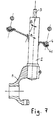
- Figure 1 shows such a suspension. It is known that this type of suspension comprises a strut 1 consisting essentially of a shock absorber participating at the same time in guiding the wheel.
- the damper comprises a body 2 and a rod 3.
- the upper end 30 of the rod bears on the vehicle body at a point of articulation 31 generally materialized by an elastic articulation.
- a helical spring 4 is mounted between an upper cup 40 and a lower cup 41.
- the lower cup 41 is supported on the body 2 of the shock absorber and the upper cup 40 is supported on the body of the vehicle, generally also by the through filtering carried out by said elastic articulation, filtering which may in certain embodiments be the same for the spring and for the damper.
- the body 2 is made integral with a hub carrier 5. There is therefore no degree of freedom between the body 2 and the hub carrier 5.
- a lower arm 6 is articulated on one side on the body of the vehicle and of the other on the hub carrier 5 by the articulation 65.
- the hub carrier 5 supports a hub 50, on which is mounted a wheel 51 fitted with its tire 52.
- the strut 1 exerts forces on the body from both the spring and the shock absorber. Although the exact location of the point of application of these forces is difficult, and depends in particular on the exact construction of the strut 1, it is known that the control of the shearing force which the rod 3 of the shock absorber undergoes is decisive for the proper functioning of suspensions of this type.
- the reaction R ⁇ of the vehicle body on the strut Its direction passes through point C, this being defined by the intersection of the effort B ⁇ exerted by the lower arm 6 on the joint 65 and the result of the forces S ⁇ that the ground exerts on the tire 52.
- the present invention provides means for the practical optimization of each of the vehicles produced in series. Indeed, it turned out that the inevitable dispersions of The characteristics of all the components of the suspension, and more specifically of the strut, could cause quite significant variations in behavior from one vehicle to another.
- the invention proposes the elements necessary for optimization and a method for optimizing the distribution of the reaction. R ⁇ between the push P ⁇ of spring 4 and shearing force T ⁇ in the rod 3, as well as the torque Cp exerted by the spring around the pivot axis.
- the invention proposes to introduce into a strut comprising a spring whose inclination has been calculated beforehand so that the residual shearing force T ⁇ is optimized, for example made as low as possible, elements making it possible to more finely adjust the value of this residual shear force T ⁇ or of the couple Cp.
- T ⁇ and of the torque Cp actually obtained on production vehicles.
- the objective of the invention is to be able to act on the location of the centers of thrust of the spring on the upper cup and on the lower cup, as well as on the orientation of said thrusts, without acting on the usual parameters of geometry of a suspension, which are the camber angle, the tilt angle of the pivot, and the caster angle, which remain unchanged.
- the invention provides a strut for MacPherson type wheel suspension, comprising a shock absorber provided with a body and a rod, said leg comprising a helical spring surrounding said rod, comprising a lower bearing cup supported by the shock absorber body, said lower cup comprising a lower seat receiving one of the ends of said spring, and an upper bearing cup intended to bear on the body of the vehicle, where appropriate by means of a connecting member, said upper cup comprising an upper seat receiving the other end of said spring, said upper cup being traversed by said rod, the damper body having a bearing surface for attachment to a hub carrier cooperating with means of 'hooking, said hub holder defining an axis of rotation of said wheel, said hooking means imposing a predetermined azimuthal position between the body and the hub carrier, characterized in that said leg comprises means for adjusting the relative position of the axis of the spring with respect to said bearing hanging.
- the means for hooking to a carrier hub comprise means for indexing (that is to say for locating) the relative orientation of the body of the shock absorber with respect to the hub carrier, said indexing means being arranged on or in the vicinity of the bearing hanging. It is for example a graduated sector allowing to locate and make changing the relative position of the body 2 with respect to the hub carrier 5. This thus acts on the relative angular position and / or on the eccentricity of the lower cup.
- the strut has a ball stop 42 visible in FIGS. 2, 5, 6, 8 to 14, 22, 23, and 26 to 30 whose role is that the deflection is not thwarted by the spring 4.
- FIG. 5 illustrates a leg whose ball stop 42, also located under the lower cup 41, is inclined so that the normal to the bearing surface of the lower cup forms an angle ⁇ with respect to the axis of the rod 3.
- FIG. 6 shows that, by relative rotation of the body 2 with respect to the hub carrier 5, the orientation of the axis of the thrust ball 42 and the attitude of the spring 4 on the cup are varied lower 41.
- a combination of the eccentricity e and the inclination ⁇ can also be used.
- the lower cup 41 d 'support of the spring 4 is integral with the body 2 of the damper.
- the axis of the lower cup is inclined at an angle ⁇ relative to the axis of the shock body 2 and / or offset by a distance e relative to the axis of the shock body 2.
- the adjustment consists in angularly orienting the body 2 of the shock absorber relative to the hub carrier 5. The modification of said orientation makes it possible to change the position of the lower cup 41 relative to the upper cup and thus to adjust the direction spring thrust 4.
- Figures 8 to 12 illustrate an adjustment by rotation of an eccentric: the lower cup 41 is mounted on the damper body 2 via an eccentric 420 adjustable in rotation.
- the eccentric can be part of the ball stop 42 ( Figures 10 and 12) or be independent of it ( Figures 8, 9 and 11).
- the rotation of the eccentric 420 relative to the body 2 (FIGS. 8 and 9), or the rotation of the eccentric 420 relative to the cup 41 (FIG. 11) displaces the cup 41 or relative to the body 2.
- Figures 13 and 14 show the setting using a wedge wedge 71 having a section of maximum thickness and a section of minimum thickness diametrically opposite to the previous one, the thickness varying continuously between said sections, said wedge wedge 71 supporting said lower cup by one of its faces, said wedge wedge 71 being adjustable by relative rotation.
- This arrangement finds application for example in the case of a front strut, in which the ball stop 42 is located under the lower cup 41.
- the use as explained of a wedge such as the wedge 71 to support the upper cup (use not shown) would also act on the upper cup.
- the wedge wedge 71 is interposed between the lower cup 41 and the ball stop 42 (fig. 13), or between the ball stop 42 and the support flange 25 secured to the body 2 of the shock absorber (fig. 14).
- the axis of the bearing face of the flange 26 can be inclined at an angle ⁇ relative to the axis of the body 2 of the shock absorber (fig. 15), and could also support a shim skew.
- the adjustment consists in angularly orienting the wedge wedge 71, with respect to said cup 41 (FIG. 13) or with respect to said body 2 (FIG. 14).
- the wedge wedge 71 will be preferably secured to the lower cup 41 (fig. 13) or to the support flange 25 (fig. 14) by means of a mechanical stop device, or by collage.
- the same adjustment principle also applies to struts lacking a ball stop, or to struts in which the ball stop 42 is located above the upper spring support cup.
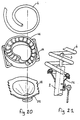
- FIG. 16 illustrates a ring 78 forming a spacer interposed between spring 4 and cup, here the lower cup 41.
- the seat of one of the cups is materialized by said ring 78 disposed around the periphery of said cup 41, which can rotate in rotation around said periphery , said ring forming a spacer between the spring and said cup, the bearing surface of said ring on the cup being a surface of revolution, said ring forming having a section of maximum thickness and a section of minimum thickness, said ring being adjustable by relative rotation with respect to said cup.
- the ring 79 in addition to a variable thickness, has a seat eccentric with respect to the bearing surface on the cup 41, which is of revolution.
- the adjustment is made by relative rotation of the ring 78 or 79 relative to the cup 41, the spring 4 remaining in abutment on the ring without relative movement.
- the eccentric nature of the ring can also be used independently of the thickness variation property, if the shape of the spring allows it.
- said adjustment means essentially comprise the following arrangement: the lower cup 41 is placed on a flange 21 secured to the body 2 of the shock absorber, said flange forming a slide guiding said cup in translation in a plane cutting the axis of l shock absorber, said leg comprising means for selecting a chosen relative position of said lower cup relative to said flange and for immobilizing said lower cup and said flange in the chosen position.
- the relative translation between lower cup 41 and flange 21 takes place in a direction perpendicular to the plane of FIGS. 19 and 21.
- a toothing 22 is produced on two parallel and opposite edges of the flange 21 forming a slide (FIG. 18 and 20). This toothing provides both guiding in translation (by said parallel edges) of the lower cup 41 and allows immobilization in the relative position, by the toothing itself.
- the lower cup 41 can be produced by stamping a metal sheet ( Figures 18 and 19).
- the lower cup has two folded parallel edges.
- a rib 23, visible in FIG. 18, is produced in the middle of each of the folded edges. This rib 23 engages in the teeth 22 of the flange 21 to freeze the chosen relative position.
- the lower cup 41 can also be produced by molding ( Figures 20 and 21). This lower cup then has two ears 24 (FIG. 20) having on their lower face an imprint complementary to the toothing 22. This imprint engages in the toothing 22 of the flange 21 in order to freeze the chosen relative position.
- the adjustment elements described above can of course be useful for making corrections, whatever the method of detecting vehicle behavior disorders. They can be used separately or, for some of them, combined together.
- the invention makes it possible to comply with much closer tolerances on the real characteristics of the struts mounted on vehicles.
- the adjustment elements can be used in conjunction with a measurement, for example of the shearing force applied to the rod, for example by decoupling the top of the rod from the upper cup or more generally from the body connection member. , and by measuring the effort necessary to maintain the top of the rod in its initial configuration, or by any suitable method.
- the measurement of the characteristics of the steering system is also relevant for act on the adjustment elements.
- the shear force on the rod is also relevant for act on the adjustment elements.
- the torque around the pivot axis is also relevant for act on the adjustment elements.
- the torque at the wheel is also relevant for act on the adjustment elements.
- parameters that can be measured such as the shear force on the rod, the torque around the pivot axis, or the torque at the wheel, or other parameters if they are representative, directly or indirectly, of the operation of the struts in real use on the vehicle for which they are designed.
- the plate 90 is mounted on the frame 92 by means of a first group of three links B1, B2, B3, mounted by ball joint or by equivalent elastic decoupling which has in measures the advantage of not introducing friction (localized thinning of the rod) on the one hand on the face of said plate 90 opposite the face receiving said connecting member, and on the other hand on configurable housings arranged on the frame 92 opposite said plate 90, the precise position of said housings essentially constituting said configuration means, and by means of a second group of three coplanar links B4, B5, B6, mounted by ball joint on the one hand on said opposite plate and on the other hand on said frame so that their plane is perpendicular to the axis of the rod, at least one of said links comprising a sensor I of tensile and compression force.
- at least two of said links of the second group B4, B5, B6, or all three include such a sensor I.
- the best location for E is that it corresponds to the place in space in relation to the strut where point C is located when the strut is mounted on the vehicle for which it is designed. If we want to measure the torque Cp, the best location for E is that it corresponds to the place in space in relation to the strut where point 66 is located when the strut is mounted on the vehicle for which it is designed. In both cases, a good approximation of the measurements is obtained without changing the bench settings, that is to say by carrying out the two measurements with a single configuration of the bench, if the latter is adjusted so that point E either located on the segment connecting 66 to C.
- point E results from the complete geometric characteristics of the vehicle concerned.
- the reader is referred to the introductory part of this memo, where it is recalled, with the help of FIG. 1, where the points C and 66 are located, depending on the exact shape of the hub carrier, of the position of the joint 65, the size of the tires.
- the bench is adjusted by a mechanism allowing the housing to be moved, or the bench is associated with a certain number of cassettes adjusted in advance, for installation on a rapid bench, for example by snap-fastening, each cassette corresponding to a vehicle .
- the strut was previously assembled. However, its measurement on a bench requires that the shock absorber rod is not linked to the upper cup. For all the legs intended to be mounted on the body via the upper cup, it suffices not to mount (or dismantle) the end of the rod, and to push it back into the body. In the case where the upper cup is mounted on the end of the rod, it is advisable to provide an adaptation part having the same configuration as the top of the rod, in order to be able to mount the leg on the measuring bench, while leaving the shock absorber rod unstressed and pushed back into the shock body.
- the leg is mounted on the plate 90 by its upper cup 40 (or by an adaptation piece) exactly as it would be mounted on the body of the vehicle, that is to say so that the elastic articulation of the rod of the shock absorber (point 31) is located in the appropriate place.
- the body 2 of the shock absorber is mounted on the mandrel 91, by embedding.
- the bench allows the spring 4 to be compressed into the position it will have under the effect of the weight of the vehicle, by relative approximation of the mandrel 91 relative to the plate 90, by a translation parallel to the axis of the damper.
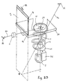
- FIG. 23 shows an alternative embodiment of the measurement bench, in which the plate 90 is mounted on the frame 92 by means of a plate P3 mounted by axis on the one hand on the face of said plate 90 opposite the face receiving said connecting member, and on the other hand on the frame 92 (configurable axis) opposite said plate 90 (equivalent elastic axes or blades), and by means of a link B3 whose axis intersects the defined plane by the plate P3 at E, mounted by ball joints on the one hand on the face of said plate opposite to the face receiving said connecting member, and on the other hand in a configurable housing arranged on the frame 92 opposite said plate 90, the determination of the position of said housing and of said configurable axis essentially constituting said configuration means, and by means of a second link B4 mounted by ball joint on the one hand on said plate 90 and on the other hand on said frame 92 so that said second rod is perpendicular to the axis of the rod, said second rod comprising a sensor I of tensile and compression
- FIG. 24 shows another alternative embodiment of the measurement bench, in which the plate 90 comprises a column 900 arranged substantially parallel to the strut. It is mounted on the frame 92 by means of two links B1 and B2 which are arranged, with respect to the strut to be measured, in the plane of the lower suspension triangle (see arm 6 in FIG. 1).
- the links B1 and B2 converge at a point D which coincides with the geometric location of point 66 (center of the ball 65 of the arm 6, see Figure 1).
- the plate 90 is mounted on the frame 92 also by means of a link B3 arranged in the plane of the wheel, in the direction of the load. S ⁇ .
- the axis of the link B3 passes through the point C.
- the plate 90 is mounted on the frame 92 also by means of the links B4 and B6 located in a plane perpendicular to the axis of the shock absorber, are perpendicular to each other and converge at point 31.
- the plate 90 is mounted on the frame 92 also by means of a link B5 parallel to the link B6.
- the plane defined by the links B5 and B6 is perpendicular to the axis of the pivot 80 and cuts it at point 31.
- the links B3, B4, B5 and B6 are fitted with sensors I.
- the rod of the shock absorber is not coupled to the cup 40, the spring is compressed just as the nominal load of the vehicle would.
- This measurement bench records the following values: B4 directly measures the shear force transverse to the shock absorber rod, B5 and B6 measure the shear force longitudinal to the shock absorber rod, B5 measures the torque Cp generated by the spring around the pivot axis 80, and B3 measures the vertical load seen by the vehicle wheel in the same state of compression of the spring.
- B4 directly measures the shear force transverse to the shock absorber rod
- B5 and B6 measure the shear force longitudinal to the shock absorber rod
- B5 measures the torque Cp generated by the spring around the pivot axis 80
- B3 measures the vertical load seen by the vehicle wheel in the same state of compression of the spring.
- the configuration of the bench is analogous to what has been explained before, by acting on the anchors of the various rods on the frame.
- Such a bench therefore comprises a first group of two rods B1 and B2 coplanar and axes concurrent with the pivot axis 80, substantially at the center of the ball joint of the lower arm, a second group of two rods B4 and B6 coplanar and arranged so that their plane is perpendicular to the axis of the rod at the height of said elastic articulation receiving said rod, and it further comprises a rod B5 coplanar with B6 so that the plane formed by the rods B5 and B6 is perpendicular to the pivot axis 80 and cuts said pivot axis at the height of said elastic articulation, and a link B3 located in the median plane of the wheel.
- a bench having two measurement systems as described, and making it possible to simultaneously receive a right leg and a left leg intended for the same vehicle.
- Such a bench has the advantage of being able to obtain, under conditions extremely close to reality, a direct reading of the combined effect that these two legs will exert on the vehicle's steering system, by appropriate processing of the signal delivered by the sensors of the two measurement systems. The result of these measurements makes it possible to finely adjust the combined effect of the two legs on the steering system by acting on an adjustment element of each of these two legs.
- FIG. 25 An example of such an adjustment bench is shown in Figure 25. After adjustment, these two legs are paired and mounted on the same vehicle. We see two positions identical to what has just been exposed, each provided with a plate 90 and a mandrel 91.
- the links B1, B2, B3 are adjusted to compete at point E, chosen according to the geometric characteristics of the vehicle to be equipped with the pair of struts. Some of these links include a tensile / compression force sensor I as explained above.
- the two mandrels 91 are mounted on cross member 94 sliding on the frame 92.
- the cross member 94 slides along the frame 92 under the action of the jack 93. In this way, the bench makes it possible to simultaneously compress the springs of each of the struts .
- the invention also proposes a specific adaptation to steering trains, illustrated in FIGS. 26 to 34.
- a turning movement actuated by the steering system connected to the hub carrier 5 by a link 53 via a ball joint
- the leg, hub carrier, hub and wheel assembly pivots around the pivot axis 80, defined by points 31 and 66.
- the strut 1 has a thrust bearing 42 which allows a deflection to be carried out without biasing the spring 4 in torsion. Indeed, the thrust of the spring 4 is exerted between the body of the vehicle and the body 2 of the shock absorber. Said damper body performs a rotation about the pivot axis 80.
- This ball bearing 42 can be located either between the body and the elastic joint, or between the elastic joint and the upper cup 40 of the spring, as shown in FIGS. 26 and 27, or finally between the lower cup 41 and the body 2 of the shock absorber.
- the axis of rotation 70 of the ball bearing is generally distinct from the pivot axis 80. In all known embodiments, these two axes intersect. Indeed, the axis of the thrust ball is generally coincident with the common axis of the rod 3 and the body 2 of the shock absorber. This configuration makes it possible to [imitate the torque effects Cp that the thrust P of the spring can exert around the pivot axis 80, and which act on the balance of the steering system by means of the link 53.
- the present invention proposes an evolution of the design of the struts making it possible to control and even to finely adjust the torque effects Cp that the spring thrust causes to appear around the pivot axis 80, thus making it possible to better control the share.
- suspension struts in the behavior of the steering system without any modification to the geometry (characteristic angles and offsets) of the front axle.
- This invention therefore offers suspension designers a completely independent additional degree of design freedom. parameters usually taken into account in the definition of a front axle.
- This additional design parameter also offers a possibility of adjustment allowing easier adjustment of the strut and thus shortening the development time of the suspension of a future vehicle.
- the strut of a Mac Pherson type wheel suspension comprising a shock absorber provided with a body and a rod, said leg comprising a helical spring surrounding said rod, comprising a lower bearing cup supported by the shock absorber body, said lower cup comprising a lower seat receiving one of the ends of said spring, and an upper bearing cup intended to bear on the body of the vehicle, said upper cup comprising an upper seat receiving the other of the ends of said spring, said upper cup being traversed by said rod, the damper body comprising a bearing surface for attachment to a hub carrier cooperate with attachment means, said hub carrier defining an axis of rotation of said wheel, one of the upper and lower cups containing a ball stop authorizing the turning of the hub carrier, is characterized in that l the axis of said ball stop and the pivot axis are non-concurrent.
- the invention thus provides a strut for steering wheel suspension of the Mac Pherson type, in which the axis of rotation 70 of the ball bearing 42 is positioned so that it does not cut the pivot axis 80 This axis of rotation will thus be either parallel to the pivot axis, or not coplanar with the pivot axis. It is then possible, in these two cases, to define a distance d between these two axes. This distance d is the smallest measurable distance between two respective points on these axes. It is raised in a direction perpendicular to each of these axes, as shown in FIG. 27 or 29 in the particular case of a stop 42 located above the upper cup 40.
- the spring exerts a thrust force P on the lower cup 41.
- This thrust P passes through the ball thrust 42.
- This ball thrust 42 having a very low internal friction, the thrust P of the spring exerts under these conditions a moment of rotation zero along the axis 70 of the stop.
- This zero moment results in the fact that the thrust direction P of the spring intersects the axis 70 of the thrust bearing 42 at a point B as shown in FIGS. 28 and 29.
- the direction of thrust P from point B does not intersect the pivot axis 80, it follows that the thrust P of the spring exerts around the pivot axis 80 a torque Cp proportional to the component of said thrust P of the spring perpendicular to the pivot axis and to the distance d previously described. Perfect control of the distance d and its orientation makes it possible to give the torque Cp a very precise value.
- This distance d can be defined at the design of the strut, so as to better control the combined effects of the couples Cp of the right and left legs on the steering system.
- this distance d can be adjusted.
- This setting can thus be used in particular to bring about a possible correction of the steering behavior, during vehicle maintenance operations. It is also possible to carry out the adjustment during the leg assembly operation, thanks to a bench capable of measuring the torque Cp.
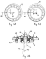
- Figures 27, 30 to 32 illustrate an eccentric ball bearing 42.
- the adjustment is made by relative rotation between a shim 72 mounted centrally in the support directly in contact with the vehicle body, said shim 72 having an eccentric housing for receiving the thrust ball 42. It can be seen, for example, that the axis of the stopper is further from the pivot axis 80 in Figure 31 than in Figure 30. In this example, the adjustment is an operation made in the vehicle maintenance workshop, or when mounting the strut on a measurement bench.
- the means for adjusting the distance d can act by translation of the stop, without changing the orientation of its axis, for example by orienting the upper ring 74 of the stop 42 which is eccentric relative to the rod 3 of the damper ( Figures 30 to 34).
- This adjustment will be defined in such a way that it will modify the spring's thrust characteristics as little as possible, and in particular its rigidity.
- This is how the translation of the stopper will preferably be carried out along a plane perpendicular to the geometric axis of the spring, and its tilting will be carried out around an axis preferably intersecting the geometric axis of the spring.
- the distance d can also be adjusted while the vehicle is running to correct a steering behavior fault as soon as it is detected.
- the fault may be noted by the driver of the vehicle.
- the correction made by adjusting the distance d will be carried out by an actuator controlled by the driver of the vehicle himself.
- Fault detection can also be automatic, for example by measuring the torque that must be exerted at the wheel to keep the vehicle on a straight path.
- the adjustment of the distance d can be controlled by a fully automatic active correction system.
- Figures 33 and 34 show an embodiment including a motorized system for varying the distance d.
- the upper ring 74 of the ball bearing 42 is supported on a low friction coating.
- This ring 74 is guided in rotation about an axis 73 perpendicular to the plane of said ring and located at a point on its periphery, and comprises, opposite this axis, an actuated rack 75 by a pinion 76 linked to the axis of an electric motorization system 77.
- This motorization 77 has an irreversibility characteristic, that is to say that a torque exerted on the axis of the pinion 76 cannot cause its rotation in the absence of electrical supply voltage.
- This motorization can be produced for example by means of an electric motor coupled to an irreversible reduction gear, for example a worm screw system, or it can be produced by means of a piezoelectric motor directly driving the pinion 75.
Abstract
Description
La présente invention concerne les suspensions de type Mac Pherson. La figure 1 représente une telle suspension. On sait que ce type de suspension comporte une jambe de force 1 constituée essentiellement par un amortisseur participant en même temps au guidage de la roue.The present invention relates to Mac Pherson type suspensions. Figure 1 shows such a suspension. It is known that this type of suspension comprises a
L'amortisseur comporte un corps 2 et une tige 3. L'extrémité supérieure 30 de la tige prend appui sur la caisse du véhicule en un point d'articulation 31 matérialisé en général par une articulation élastique. Un ressort hélicoïdal 4 est monté entre une coupelle supérieure 40 et une coupelle inférieure 41. La coupelle inférieure 41 prend appui sur le corps 2 de l'amortisseur et la coupelle supérieure 40 prend appui sur la caisse du véhicule, en général aussi par l'intermédiaire d'un filtrage réalisé par ladite articulation élastique, filtrage qui peut dans certaines réalisations être le même pour le ressort et pour l'amortisseur.The damper comprises a
Par ailleurs, le corps 2 est rendu solidaire d'un porte-moyeu 5. Il n'y a donc aucun degré de liberté entre le corps 2 et le porte-moyeu 5. Un bras inférieur 6 est articulé d'un côté sur la caisse du véhicule et de l'autre sur le porte-moyeu 5 par l'articulation 65. Le porte-moyeu 5 supporte un moyeu 50, sur lequel est montée une roue 51 équipée de son pneu 52.Furthermore, the
Dans la zone d'attache sur la caisse, la jambe de force 1 exerce des efforts sur la caisse en provenance à la fois du ressort et de l'amortisseur. Bien que la localisation exacte du point d'application de ces efforts soit difficile, et dépende notamment de la construction exacte de la jambe de force 1, il est connu que la maîtrise de l'effort tranchant que subit la tige 3 de l'amortisseur est déterminante pour le bon fonctionnement des suspensions de ce type. Pour simuler une suspension Mac Pherson, on peut considérer la réaction ![]()
![]()
![]()
![]()
![]()
![]()
![]()
![]()
![]()
![]()
![]()
![]()
![]()
![]()
![]()
![]()
![]()
![]()
![]()
![]()
Pour obtenir un bon fonctionnement de la jambe (pas ou peu de frottements secs, usure minime, ...), on sait qu'il convient de contrôler très étroitement l'effort tranchant ![]()
![]()
Par ailleurs, les recherches du déposant l'on conduit à observer que la résultante des efforts exercés par le ressort est susceptible d'exercer un couple Cp autour de l'axe de pivot, défini par le point d'articulation 31 et le centre 66 de l'articulation 65. Ce couple agit sur l'équilibre du système de direction. Pour obtenir un bon fonctionnement du système de direction, il est nécessaire de bien maîtriser (par exemple de minimiser) l'effet combiné des couples Cp issus des jambes droite et gauche.Furthermore, the applicant's research leads us to observe that the result of the forces exerted by the spring is likely to exert a torque Cp around the pivot axis, defined by the
Malheureusement, de nombreuses voitures souffrent encore à l'heure actuelle de mauvaises caractéristiques de suspensions et/ou de direction. Le comportement dynamique d'un véhicule dépend d'une quantité considérable de paramètres, dont certains ont une influence encore mal connue mais qui peut très bien être pourtant prépondérante. Il en résulte que, alors même que le concepteur a bien respecté toutes les règles de l'art pour concevoir la suspension, le résultat n'est pas toujours à la hauteur du soin apporté à la conception.Unfortunately, many cars today still suffer from poor suspension and / or steering characteristics. The dynamic behavior of a vehicle depends on a considerable amount of parameters, some of which have an influence that is still poorly understood but which may very well be predominant. It follows that, even though the designer has respected all the rules of the art in designing the suspension, the result is not always up to the care taken in the design.
La présente invention propose des moyens permettant l'optimisation pratique de chacun des véhicules fabriqués en série. En effet, il s'est avéré que les inévitables dispersions des caractéristiques de tous les composants de la suspension, et plus précisément de la jambe de force, pouvaient causer des variations de comportement assez importantes d'un véhicule à l'autre. L'invention propose les éléments nécessaires à l'optimisation et une méthode d'optimisation de la répartition de la réaction ![]()
![]()
![]()
![]()
![]()
![]()
L'invention propose d'introduire, dans une jambe de force comportant un ressort dont l'inclinaison a été calculée préalablement de façon à ce que l'effort tranchant résiduel ![]()
![]()
![]()
![]()
![]()
![]()
L'objectif de l'invention est de pouvoir agir sur la localisation des centres de poussée du ressort sur la coupelle supérieure et sur la coupelle inférieure, ainsi que sur l'orientation desdites poussées, sans agir sur les paramètres habituels de géométrie d'une suspension, que sont l'angle de carrossage, l'angle d'inclinaison du pivot, et l'angle de chasse, qui restent inchangés.The objective of the invention is to be able to act on the location of the centers of thrust of the spring on the upper cup and on the lower cup, as well as on the orientation of said thrusts, without acting on the usual parameters of geometry of a suspension, which are the camber angle, the tilt angle of the pivot, and the caster angle, which remain unchanged.
L'invention propose une jambe de force pour suspension de roue de type Mac Pherson, comportant un amortisseur pourvu d'un corps et d'une tige, ladite jambe comportant un ressort hélicoïdal entourant ladite tige, comportant une coupelle inférieure d'appui supportée par le corps de l'amortisseur, ladite coupelle inférieure comportant un siège inférieur recevant l'une des extrémités dudit ressort, et une coupelle supérieure d'appui destinée à prendre appui sur la caisse du véhicule, le cas échéant par l'intermédiaire d'un organe de liaison, ladite coupelle supérieure comportant un siège supérieur recevant l'autre des extrémités dudit ressort, ladite coupelle supérieure étant traversée par ladite tige, le corps d'amortisseur comportant une portée d'accrochage à un porte-moyeu coopérant avec des moyens d'accrochage, ledit porte-moyeu définissant un axe de rotation de ladite roue, lesdits moyens d'accrochage imposant une position azimutale prédéterminé entre le corps et le porte-moyeu, caractérisé en ce que ladite jambe comporte des moyens de réglage de la position relative de l'axe du ressort par rapport à ladite portée d'accrochage.The invention provides a strut for MacPherson type wheel suspension, comprising a shock absorber provided with a body and a rod, said leg comprising a helical spring surrounding said rod, comprising a lower bearing cup supported by the shock absorber body, said lower cup comprising a lower seat receiving one of the ends of said spring, and an upper bearing cup intended to bear on the body of the vehicle, where appropriate by means of a connecting member, said upper cup comprising an upper seat receiving the other end of said spring, said upper cup being traversed by said rod, the damper body having a bearing surface for attachment to a hub carrier cooperating with means of 'hooking, said hub holder defining an axis of rotation of said wheel, said hooking means imposing a predetermined azimuthal position between the body and the hub carrier, characterized in that said leg comprises means for adjusting the relative position of the axis of the spring with respect to said bearing hanging.
L'invention sera mieux comprise par la description qui va suivre, d'un exemple donné à titre non limitatif, en se référant au dessin annexé sur lequel :
- la figure 1 montre une suspension Mac Pherson,
- les figures 2 à 4 et 8 à 12 illustrent un réglage par excentrique agissant par déplacement de la coupelle inférieure par rapport à l'axe de la tige de l'amortisseur,
- les figures 5 à 7 et 13 à 15 illustrent un réglage par variation de l'inclinaison de la coupelle inférieure par rapport à l'orientation de la tige de l'amortisseur,
- les figures 16 et 17 illustrent un réglage par variation géométrique de l'appui du ressort sur la coupelle,
- les figures 18 à 21 illustrent un réglage agissant par translation de la coupelle inférieure par rapport à l'axe de la tige d'amortisseur,
- les figures 22, 23 et 24 illustrent trois bancs de mesure selon l'invention,
- la figure 25 illustre un banc de mesure double spécifique à un aspect de l'invention,
- les figures 26 et 27 montrent, de face et de côté, une suspension McPherson pour roue directrice,
- les figures 28 et 29 schématisent les principaux axes en présence et les forces principales,
- les figures 30, 31 et 32 illustrent une possibilité de réglage,
- les figures 33 et 34 illustrent un équipement pour réglage par commande électrique.
- FIG. 1 shows a Mac Pherson suspension,
- FIGS. 2 to 4 and 8 to 12 illustrate an eccentric adjustment acting by displacement of the lower cup relative to the axis of the shock absorber rod,
- FIGS. 5 to 7 and 13 to 15 illustrate an adjustment by variation of the inclination of the lower cup relative to the orientation of the rod of the shock absorber,
- FIGS. 16 and 17 illustrate an adjustment by geometric variation of the support of the spring on the cup,
- FIGS. 18 to 21 illustrate an adjustment acting by translation of the lower cup relative to the axis of the damper rod,
- FIGS. 22, 23 and 24 illustrate three measurement benches according to the invention,
- FIG. 25 illustrates a double measurement bench specific to one aspect of the invention,
- FIGS. 26 and 27 show, from the front and from the side, a McPherson suspension for a steering wheel,
- FIGS. 28 and 29 schematize the main axes involved and the main forces,
- FIGS. 30, 31 and 32 illustrate a possibility of adjustment,
- Figures 33 and 34 illustrate an equipment for adjustment by electrical control.
Aux figures 2 à 7, on décrit des jambes de forces pour lesquelles le réglage s'effectue par rotation relative du corps 2 de l'amortisseur par rapport au porte-moyeu 5. Dans ce cas, les moyens d'accrochage à un porte-moyeu comportent des moyens d'indexation (c'est à dire de repérage) de l'orientation relative du corps de l'amortisseur par rapport au porte-moyeu, lesdits moyens d'indexations étant disposés sur ou au voisinage de la portée d'accrochage. C'est par exemple un secteur gradué permettant de repérer et de faire évoluer la position relative du corps 2 par rapport au porte-moyeu 5. On agit ainsi sur la position angulaire relative et/ou sur l'excentration de la coupelle inférieure.Figures 2 to 7, the struts are described for which the adjustment is effected by relative rotation of the
Avant de décrire les moyens de réglage explicités ci-dessous, rappelons que, dans le cas de roues directrices, la jambe de force comporte une butée à bille 42 visible aux figures 2, 5, 6, 8 à 14, 22, 23, et 26 à 30 dont le rôle est que le braquage ne soit pas contrarié par le ressort 4.Before describing the adjustment means explained below, it should be recalled that, in the case of steered wheels, the strut has a
Dans le cas d'une jambe de force dans laquelle la butée à billes 42 est située sous la coupelle inférieure 41 d'appui du ressort 4, la butée à billes 42 est centrée sur une collerette excentrique 27, pour décaler le centre de la butée à bille 42 d'une distance e par rapport à l'axe de l'amortisseur 2 (Fig. 2 à 4). En comparant les figures 3 et 4, on voit qu'une rotation ε entre le corps 2 de l'amortisseur et le porte-moyeu 5 déplace le centre de la butée à bille 42, ce qui décale de façon correspondante la coupelle inférieure 41.In the case of a strut in which the
La figure 5 illustre une jambe dont la butée à bille 42, également située sous la coupelle inférieure 41, est inclinée de telle sorte que la normale à la surface d'appui de la coupelle inférieure forme un angle α par rapport à l'axe de la tige 3. La figure 6 montre que, par rotation relative du corps 2 par rapport au porte-moyeu 5, on fait varier l'orientation de l'axe de la butée à billes 42 et l'attitude du ressort 4 sur la coupelle inférieure 41. Une combinaison de l'excentration e et de l'inclinaison α peut être également utilisée.FIG. 5 illustrates a leg whose ball stop 42, also located under the
Dans le cas d'une jambe de force de train arrière, ou d'une jambe de train avant dans laquelle la butée à billes est située au dessus de la coupelle supérieure d'appui du ressort (figure 7), la coupelle inférieure 41 d'appui du ressort 4 est solidaire du corps 2 de l'amortisseur. L'axe de la coupelle inférieure est incliné d'un angle β par rapport à l'axe du corps d'amortisseur 2 et/ou excentré d'une distance e par rapport à l'axe du corps d'amortisseur 2. Là encore, le réglage consiste à orienter angulairement le corps 2 de l'amortisseur par rapport au porte-moyeu 5. La modification de ladite orientation permet de changer la position de la coupelle inférieure 41 par rapport à la coupelle supérieure et ainsi d'ajuster la direction de poussée du ressort 4.In the case of a rear axle strut, or a front axle strut in which the ball bearing is located above the upper spring support cup (FIG. 7), the lower cup 41 d 'support of the
Les figures 8 à 12 illustrent un réglage par rotation d'un excentrique : la coupelle inférieure 41 est montée sur le corps 2 d'amortisseur par l'intermédiaire d'un excentrique 420 réglable en rotation. L'excentrique peut faire partie de la butée à bille 42 (figures 10 et 12) ou être indépendant de celle-ci (figures 8, 9 et 11). La rotation de l'excentrique 420 par rapport au corps 2 (figure 8 et 9), ou la rotation de l'excentrique 420 par rapport à la coupelle 41 ( figure 11) déplace la coupelle 41 pu rapport au corps 2. On pourrait aussi monter la coupelle supérieure sur la caisse par le biais d'un organe de liaison pourvu d'un excentrique.Figures 8 to 12 illustrate an adjustment by rotation of an eccentric: the
Les figures 13 et 14 montrent le réglage utilisant une cale biaise 71 comportant une section d'épaisseur maximale et une section d'épaisseur minimale diamétralement opposée à la précédente, l'épaisseur variant continûment entre lesdites sections, ladite cale biaise 71 supportant ladite coupelle inférieure par l'une de ses faces, ladite cale biaise 71 étant réglable par rotation relative. Cette disposition trouve application par exemple dans le cas d'une jambe de force de train avant, dans laquelle la butée à billes 42 est située sous la coupelle inférieure 41. Bien entendu, l'utilisation comme expliquée d'une cale biaise telle que la cale 71 pour supporter la coupelle supérieure (utilisation non représentée) permettrait aussi d'agir sur la coupelle supérieure.Figures 13 and 14 show the setting using a
La cale biaise 71, dont les faces sont inclinées l'une par rapport à l'autre d'un angle γ, est intercalée entre la coupelle inférieure 41 et la butée à billes 42 (fig. 13), ou entre la butée à billes 42 et la collerette d'appui 25 solidaire du corps 2 de l'amortisseur (fig. 14). En variante, l'axe de la face d'appui de la collerette 26 peut être incliné d'un angle α par rapport à l'axe du corps 2 de l'amortisseur (fig. 15), et pourrait en outre supporter une cale biaise. Le réglage consiste à orienter angulairement la cale biaise 71, par rapport à ladite coupelle 41 (figure 13) ou par rapport audit corps 2 (figure 14). La modification de ladite orientation permet de changer l'inclinaison de la coupelle inférieure 41 par rapport à l'axe de l'amortisseur 2, et ainsi d'ajuster la direction de poussée du ressort 4. Après réglage, la cale biaise 71 sera de préférence solidarisée avec la coupelle inférieure 41 (fig. 13) ou avec la collerette d'appui 25 (fig. 14) au moyen d'un dispositif d'arrêt mécanique, ou par collage. Le même principe de réglage s'applique également à des jambes de force dépourvues de butée à billes, ou à des jambes de force dans lesquelles la butée à billes 42 est située au dessus de la coupelle supérieure d'appui du ressort.The
La figure 16 illustre un anneau 78 formant entretoise intercalé entre ressort 4 et coupelle, ici la coupelle inférieure 41. Le siège d'une des coupelles est matérialisé par ledit anneau 78 disposé sur le pourtour de ladite coupelle 41, mobile en rotation sur ledit pourtour, ledit anneau formant entretoise entre le ressort et ladite coupelle, la surface d'appui dudit anneau sur la coupelle étant une surface de révolution, ledit anneau formant ayant une section d'épaisseur maximale et une section d'épaisseur minimale, ledit anneau étant réglable par rotation relative par rapport à ladite coupelle. A la figure 17, on voit une variante dans laquelle l'anneau 79, outre une épaisseur variable, présente un siège excentré par rapport à la surface d'appui sur la coupelle 41, qui est de révolution. Dans les deux cas, le réglage se fait par rotation relative de l'anneau 78 ou 79 par rapport à la coupelle 41, le ressort 4 restant en appui sur l'anneau sans mouvement relatif. Le caractère excentrique de l'anneau peut aussi être utilisé indépendamment de la propriété de variation d'épaisseur, si l'allure du ressort le permet.FIG. 16 illustrates a
Dans le cas d'une jambe de force de train non directeur ou de train directeur dans lequel la butée à billes est située au dessus de la coupelle supérieure d'appui du ressort (figures 18 à 21), on peut aussi réaliser une jambe de force dans laquelle lesdits moyens de réglage comprennent essentiellement la disposition suivante : la coupelle inférieure 41 est posée sur une collerette 21 solidaire du corps 2 de l'amortisseur, ladite collerette formant glissière guidant ladite coupelle en translation dans un plan coupant l'axe de l'amortisseur, ladite jambe comportant des moyens pour sélectionner une position relative choisie de ladite coupelle inférieure par rapport à ladite collerette et pour immobiliser ladite coupelle inférieure et ladite collerette dans la position choisie.In the case of a non-steer or steer train strut in which the ball stop is located above the upper spring support cup (Figures 18 to 21), it is also possible to make a strut force in which said adjustment means essentially comprise the following arrangement: the
Dans l'exemple décrit, la translation relative entre coupelle inférieure 41 et collerette 21 se fait selon une direction perpendiculaire au plan des figures 19 et 21. Une denture 22 est réalisée sur deux bords parallèles et opposés de la collerette 21 formant glissière (figure 18 et 20). Cette denture assure à la fois le guidage en translation (par lesdits bords parallèles) de la coupelle inférieure 41 et permet l'immobilisation dans la position relative, par la denture elle-même.In the example described, the relative translation between
La coupelle inférieure 41 peut être réalisée par emboutissage d'une feuille métallique (figures 18 et 19). Dans ce cas, la coupelle inférieure comporte deux bords parallèles repliés. Une nervure 23, visible à la figure 18, est réalisée au milieu de chacun des bords repliés. Cette nervure 23 vient s'engager dans la denture 22 de la collerette 21 pour figer la position relative choisie.The
La coupelle inférieure 41 peut également être réalisée par moulage (figures 20 et 21). Cette coupelle inférieure possède alors deux oreilles 24 (figure 20) présentant à leur face inférieure une empreinte complémentaire à la denture 22. Cette empreinte vient s'engager dans la denture 22 de la collerette 21 pour figer la position relative choisie.The
Les éléments de réglage décrits ci-dessus peuvent bien entendu être utiles pour apporter des corrections, quelle que soit la méthode de détection des troubles de comportement de véhicule. Ils peuvent être utilisés séparément ou, pour certains d'entre eux, combinés ensemble. L'invention permet de respecter des tolérances bien plus étroites sur les caractéristiques réelles des jambes de forces montées sur les véhicules. Les éléments de réglage peuvent être utilisés en liaison avec une mesure, par exemple de l'effort tranchant appliqué sur la tige, par exemple en découplant le haut de la tige de la coupelle supérieure ou plus généralement de l'organe de liaison à la caisse, et en mesurant l'effort nécessaire pour maintenir le haut de la tige dans sa configuration initiale, ou par toute méthode convenable. Si l'on souhaite agir sur l'effet combiné des couples Cp, la mesure des caractéristiques du système de direction, par exemple le couple exercé au volant, pour maintenir en ligne droite le véhicule en roulage sur un dévers donné, est également pertinente pour agir sur les éléments de réglage. Il existe donc plusieurs paramètres susceptibles d'être mesurés, comme l'effort tranchant sur la tige, le couple de rotation autour de l'axe de pivot, ou le couple au volant, ou d'autres paramètres encore s'ils sont représentatifs, directement ou indirectement, du fonctionnement des jambes de force en usage réel sur le véhicule pour lequel elles sont dessinées.The adjustment elements described above can of course be useful for making corrections, whatever the method of detecting vehicle behavior disorders. They can be used separately or, for some of them, combined together. The invention makes it possible to comply with much closer tolerances on the real characteristics of the struts mounted on vehicles. The adjustment elements can be used in conjunction with a measurement, for example of the shearing force applied to the rod, for example by decoupling the top of the rod from the upper cup or more generally from the body connection member. , and by measuring the effort necessary to maintain the top of the rod in its initial configuration, or by any suitable method. If one wishes to act on the combined effect of the couples Cp, the measurement of the characteristics of the steering system, for example the torque exerted at the steering wheel, to keep the vehicle in a straight line while driving on a given slope, is also relevant for act on the adjustment elements. There are therefore several parameters that can be measured, such as the shear force on the rod, the torque around the pivot axis, or the torque at the wheel, or other parameters if they are representative, directly or indirectly, of the operation of the struts in real use on the vehicle for which they are designed.
On peut ainsi envisager d'affiner le réglage des véhicules en fin de chaîne de fabrication. Ils peuvent aussi être utilisés de façon plus expérimentale, en observant l'influence du réglage par exemple grâce à un plan d'expérience pour chaque véhicule équipé de jambes de force selon l'invention, et en bâtissant ainsi des règles de correction à usage des spécialistes des trains roulants. Ils peuvent ainsi notamment être utilisés pour effectuer un réglage sur véhicule, au cours d'opérations d'entretien.We can thus consider refining the adjustment of vehicles at the end of the production chain. They can also be used in a more experimental way, by observing the influence of the adjustment, for example by means of an experience plan for each vehicle fitted with struts according to the invention, and thereby building correction rules for the use of running gear specialists. They can thus in particular be used to carry out an adjustment on a vehicle, during maintenance operations.
Suivant un autre aspect de l'invention' il est proposé d'intervenir sur les jambes pendant leur fabrication, avant montage sur véhicule. On effectue une mesure de l'effort tranchant ![]()
![]()
Les figures 22, 23 et 24 illustrent un banc de mesure d'une jambe d'une suspension de type Mac Pherson, ladite jambe comportant :
- un amortisseur comportant un corps et une tige, ledit corps comportant une portée d'accrochage destinée à être montée sur un porte-moyeu,
- un organe de liaison destinée à être monté sur la caisse du véhicule, recevant ladite tige et formant une articulation élastique pour celle-ci,
- un ressort hélicoïdal entourant ladite tige,
- une coupelle inférieure d'appui montée sur le corps d'amortisseur et une coupelle supérieure d'appui montée sur ledit organe de liaison, ledit ressort étant inséré entre lesdites coupelles,
- un plateau dont une face est pourvue de moyens d'accrochage de l'organe de liaison,
- un mandrin destiné à recevoir ledit corps,
- des moyens assurant un rapprochement et/ou un éloignement relatif du mandrin par rapport au plateau,
- des moyens de configuration du banc en fonction du véhicule destiné à recevoir ladite jambe,
- des moyens pour mesurer au moins une grandeur représentative des contraintes sur l'organe de liaison.
- a shock absorber comprising a body and a rod, said body comprising a coupling surface intended to be mounted on a hub carrier,
- a connecting member intended to be mounted on the vehicle body, receiving said rod and forming an elastic articulation for the latter,
- a helical spring surrounding said rod,
- a lower bearing cup mounted on the damper body and an upper bearing cup mounted on said connecting member, said spring being inserted between said cups,
- a plate, one face of which is provided with means for hooking the connecting member,
- a mandrel intended to receive said body,
- means ensuring approximation and / or relative distance of the mandrel relative to the plate,
- means for configuring the bench as a function of the vehicle intended to receive said leg,
- means for measuring at least one quantity representative of the stresses on the connecting member.
Dans un mode de réalisation particulier (fig. 22), le plateau 90 est monté sur le bâti 92 par l'intermédiaire d'un premier groupe de trois biellettes B1, B2, B3, montées par rotule ou par découplage élastique équivalent qui présente en mesure l'avantage de ne pas introduire de frottement (amincissement localisé de la biellette) d'une part sur la face dudit plateau 90 opposée à la face recevant ledit organe de liaison, et d'autre part sur des logements configurables disposés sur le bâti 92 en regard dudit plateau 90, la position précise desdits logements constituant essentiellement lesdits moyens de configuration, et par l'intermédiaire d'un second groupe de trois biellettes coplanaires B4, B5, B6, montées par rotule d'une part sur ledit plateau opposée et d'autre part sur ledit bâti de sorte que leur plan soit perpendiculaire à l'axe de la tige, l'une au moins desdites biellettes comportant un capteur I d'effort de traction et compression. De préférence, deux au moins desdites biellettes du second groupe B4, B5, B6, ou les trois, comportent un tel capteur I.In a particular embodiment (fig. 22), the
Un tel banc permet de simuler la sollicitation réelle de la jambe dans des conditions extrêmement proches de la réalité. A cette fin, il convient que les trois biellettes B1, B2, B3 concourent au point E.Such a bench makes it possible to simulate the real stress of the leg in conditions extremely close to reality. To this end, the three links B1, B2, B3 should compete at point E.
Si l'on souhaite mesurer l'effort tranchant ![]()
![]()
En tout état de cause, le point E résulte des caractéristiques géométriques complètes du véhicule concerné. Le lecteur est renvoyé à la partie introductive de ce mémoire, où l'on rappelle, avec l'aide de la figure 1, à quels endroits les points C et 66 se situent, en fonction de la forme exacte du porte-moyeu, de la position de l'articulation 65, de la taille des pneus. Le réglage du banc se fait par un mécanisme permettant de déplacer les logements, ou bien le banc est associé à un certain nombre de cassettes réglées à l'avance, à installation sur banc rapide, par exemple par encliquetage, chaque cassette correspondant à un véhicule.In any event, point E results from the complete geometric characteristics of the vehicle concerned. The reader is referred to the introductory part of this memo, where it is recalled, with the help of FIG. 1, where the points C and 66 are located, depending on the exact shape of the hub carrier, of the position of the joint 65, the size of the tires. The bench is adjusted by a mechanism allowing the housing to be moved, or the bench is associated with a certain number of cassettes adjusted in advance, for installation on a rapid bench, for example by snap-fastening, each cassette corresponding to a vehicle .
La jambe de force a été au préalable assemblée. Cependant, sa mesure sur banc impose que la tige de l'amortisseur ne soit pas liée à la coupelle supérieure. Pour toutes les jambes destinées à être montées sur la caisse par l'intermédiaire de la coupelle supérieure, il suffit de ne pas monter (ou de démonter) l'extrémité de la tige, et de repousser celle-ci dans le corps. Dans le cas où la coupelle supérieure est montée sur l'extrémité de la tige, il convient de prévoir une pièce d'adaptation ayant la même configuration que le haut de la tige, pour pouvoir monter la jambe sur le banc de mesure, tout en laissant la tige de l'amortisseur non sollicitée et repoussée dans le corps de l'amortisseur.The strut was previously assembled. However, its measurement on a bench requires that the shock absorber rod is not linked to the upper cup. For all the legs intended to be mounted on the body via the upper cup, it suffices not to mount (or dismantle) the end of the rod, and to push it back into the body. In the case where the upper cup is mounted on the end of the rod, it is advisable to provide an adaptation part having the same configuration as the top of the rod, in order to be able to mount the leg on the measuring bench, while leaving the shock absorber rod unstressed and pushed back into the shock body.
La jambe est montée sur le plateau 90 par sa coupelle supérieure 40 (ou par une pièce d'adaptation) exactement comme elle serait montée sur la caisse du véhicule, c'est à dire de façon à ce que l'articulation élastique de la tige de l'amortisseur (point 31) soit localisée à l'endroit convenable. Le corps 2 de l'amortisseur est monté sur le mandrin 91, par encastrement. Le banc permet de comprimer le ressort 4 dans la position qu'il aura sous l'effet du poids du véhicule, par rapprochement relatif du mandrin 91 par rapport au plateau 90, par une translation parallèle à l'axe de l'amortisseur.The leg is mounted on the
On procède alors à la mesure, en particulier de l'effort tranchant. Par un traitement approprié du signal délivré par le ou les capteurs, on peut obtenir une lecture directe de la force agissant au point 31 dans le plan du plateau 90. C'est l'effort tranchant que subirait la tige si elle était solidaire de l'ancrage supérieur de la jambe de force. Le capteur I de la biellette B5, si elle en est pourvue, permet également de mesurer le couple exercé par la poussée du ressort 4 autour de l'axe allant de E à 31.We then proceed to the measurement, in particular of the shearing force. By appropriate processing of the signal delivered by the sensor or sensors, it is possible to obtain a direct reading of the force acting at
Le résultat de ces mesures permet d'ajuster finement la direction de poussée du ressort, c'est dire de régler le vecteur ![]()
![]()
La figure 23 montre une variante de réalisation du banc de mesure, dans laquelle le plateau 90 est monté sur le bâti 92 par l'intermédiaire d'une plaque P3 montée par axe d'une part sur la face dudit plateau 90 opposée à la face recevant ledit organe de liaison, et d'autre part sur le bâti 92 (axe configurable) en regard dudit plateau 90 (axes ou lames élastiques équivalentes), et par l'intermédiaire d'une biellette B3 dont l'axe coupe le plan définit par la plaque P3 en E, montée par rotules d'une part sur la face dudit plateau opposée à la face recevant ledit organe de liaison, et d'autre part dans un logement configurable agencé sur le bâti 92 en regard dudit plateau 90, la détermination de la position dudit logement et dudit axe configurable constituant essentiellement lesdits moyens de configuration, et par l'intermédiaire d'une seconde biellette B4 montée par rotule d'une part sur ledit plateau 90 et d'autre part sur ledit bâti 92 de sorte que ladite seconde biellette soit perpendiculaire à l'axe de la tige, ladite seconde biellette comportant un capteur I d'effort de traction et compression. La configuration de ce banc est semblable à ce qui a été expliqué ci-dessus, et son utilisation procède des mêmes règles.FIG. 23 shows an alternative embodiment of the measurement bench, in which the
La figure 24 montre une autre variante de réalisation du banc de mesure, dans laquelle le plateau 90 comporte une colonne 900 disposée sensiblement parallèlement à la jambe de force. Il est monté sur le bâti 92 par l'intermédiaire de deux biellettes B1 et B2 qui sont disposées, par rapport à la jambe de force à mesurer, dans le plan du triangle inférieur de suspension (voir bras 6 à la figure 1). Les biellettes B1 et B2 convergent en un point D qui coïncide avec le lieu géométrique du point 66 (centre de la rotule 65 du bras 6, voir figure 1). Le plateau 90 est monté sur le bâti 92 aussi par l'intermédiaire d'une biellette B3 disposé dans le plan de la roue, dans la direction de la charge ![]()
![]()
Un tel banc comporte donc un premier groupe de deux biellettes B1 et B2 coplanaires et d'axes concourants avec l'axe de pivot 80, sensiblement au niveau du centre de la rotule du bras inférieur, un deuxième groupe de deux biellettes B4 et B6 coplanaires et disposées de sorte que leur plan soit perpendiculaire à l'axe de la tige à hauteur de ladite articulation élastique recevant ladite tige, et il comporte en outre une biellette B5 coplanaire avec B6 de sorte que le plan formé par les biellettes B5 et B6 soit perpendiculaire à l'axe de pivot 80 et coupe ledit axe de pivot à hauteur de ladite articulation élastique, et une biellette B3 située dans le plan médian de la roue.Such a bench therefore comprises a first group of two rods B1 and B2 coplanar and axes concurrent with the
Il est en outre possible d'utiliser un banc possédant deux systèmes de mesure tels que décrits, et permettant de recevoir simultanément une jambe droite et une jambe gauche destinées au même véhicule. Un tel banc présente l'avantage de pouvoir obtenir dans des conditions extrêmement proches de la réalité une lecture directe de l'effet combiné que ces deux jambes exerceront sur le système de direction du véhicule, par un traitement approprié du signal délivré par les capteurs des deux systèmes de mesure. Le résultat de ces mesures permet d'ajuster finement l'effet combiné des deux jambes sur le système de direction en agissant sur un élément de réglage de chacune de ces deux jambes.It is also possible to use a bench having two measurement systems as described, and making it possible to simultaneously receive a right leg and a left leg intended for the same vehicle. Such a bench has the advantage of being able to obtain, under conditions extremely close to reality, a direct reading of the combined effect that these two legs will exert on the vehicle's steering system, by appropriate processing of the signal delivered by the sensors of the two measurement systems. The result of these measurements makes it possible to finely adjust the combined effect of the two legs on the steering system by acting on an adjustment element of each of these two legs.
Un exemple d'un tel banc de réglage est représenté en figure 25. Après réglage, ces deux jambes sont appairées et montées sur le même véhicule. On voit deux postes identiques à ce qui vient d'être exposé, chacun pourvu d'un plateau 90 et d'un mandrin 91. Les biellettes B1, B2, B3 sont réglées pour concourir au point E, choisi en fonction des caractéristiques géométriques du véhicule devant être équipé par la paire de jambes de force. Certaines de ces biellettes comportent un capteur I d'effort de traction/compression comme expliqué ci-dessus. Les deux mandrins 91 sont montés sur traverse 94 coulissant sur le bâti 92. La traverse 94 coulisse le long du bâti 92 sous l'action du vérin 93. De la sorte, le banc permet de comprimer simultanément les ressorts de chacune des jambes de force.An example of such an adjustment bench is shown in Figure 25. After adjustment, these two legs are paired and mounted on the same vehicle. We see two positions identical to what has just been exposed, each provided with a
L'invention propose également une adaptation spécifique aux trains directeurs, illustrée aux figures 26 à 34. Au cours d'un mouvement de braquage, actionné par le système de direction relié au porte moyeu 5 par une biellette 53 par l'intermédiaire d'une rotule, l'ensemble jambe, porte-moyeu, moyeu et roue pivote autour de l'axe de pivot 80, défini par les points 31 et 66.The invention also proposes a specific adaptation to steering trains, illustrated in FIGS. 26 to 34. During a turning movement, actuated by the steering system connected to the
La jambe de force 1 comporte une butée à billes 42 qui permet d'effectuer un braquage sans solliciter le ressort 4 en torsion. En effet, la poussée du ressort 4 s'exerce entre la caisse du véhicule et le corps 2 de l'amortisseur. Ledit corps d'amortisseur effectue une rotation autour de l'axe de pivot 80. Cette butée à billes 42 peut être située soit entre la caisse et l'articulation élastique, soit entre l'articulation élastique et la coupelle supérieure 40 du ressort, comme cela est représenté aux figures 26 et 27, soit enfin entre la coupelle inférieure 41 et le corps 2 de l'amortisseur.The
Comme on le voit dans chacun de ces cas, l'axe de rotation 70 de la butée à billes est en général distinct de l'axe de pivot 80. Dans toutes les réalisations connues, ces deux axes se coupent. En effet, l'axe de la butée à billes est généralement confondu avec l'axe commun de la tige 3 et du corps 2 d'amortisseur. Cette configuration permet de [imiter les effets de couple Cp que la poussée P du ressort peut exercer autour de l'axe de pivot 80, et qui agissent sur l'équilibre du système de direction par l'intermédiaire de la biellette 53.As can be seen in each of these cases, the axis of
Malgré tous les efforts de conception visant à toujours améliorer le comportement perçu par les conducteurs, afin de non seulement construire des véhicules très sûrs, mais également des véhicules agréables à conduire, de nombreux véhicules souffrent encore aujourd'hui d'un mauvais comportement de direction. Ce comportement de direction dépend en effet d'une quantité considérable de paramètres, dont certains ont une influence mal connue mais qui peut sans doute parfois être prépondérante. Il en résulte, alors même que le concepteur a respecté toutes les règles de l'art pour dimensionner le système de direction, que le résultat ne soit pas toujours à la hauteur du soin apporté à la conception.Despite all the design efforts to always improve the behavior perceived by drivers, in order not only to build very safe vehicles, but also vehicles that are pleasant to drive, many vehicles still suffer from poor steering behavior today. . This leadership behavior depends on a considerable amount of parameters, some of which have a little-known influence, but which can no doubt sometimes be preponderant. As a result, even though the designer has respected all the rules of the art in dimensioning the steering system, the result is not always up to the care taken in the design.
La présente invention propose une évolution de la conception des jambes de force permettant de maîtriser et même d'ajuster finement les effets de couple Cp que la poussée du ressort fait apparaître autour de l'axe de pivot 80, permettant ainsi de mieux maîtriser la part des jambes de suspension dans le comportement du système de direction, sans que ne soit par ailleurs modifiée la géométrie (angles et déports caractéristiques) du train avant. Cette invention propose donc aux concepteurs de suspensions un degré de liberté de conception supplémentaire totalement indépendant des paramètres habituellement pris en compte dans la définition d'un train avant. Ce paramètre supplémentaire de conception offre de plus une possibilité de réglage permettant une mise au point plus aisée de la jambe de force et de raccourcir ainsi le temps de développement de la suspension d'un futur véhicule.The present invention proposes an evolution of the design of the struts making it possible to control and even to finely adjust the torque effects Cp that the spring thrust causes to appear around the
La jambe de force d'une suspension de roue de type Mac Pherson selon l'invention, comportant un amortisseur pourvu d'un corps et d'une tige, ladite jambe comportant un ressort hélicoïdal entourant ladite tige, comportant une coupelle inférieure d'appui supportée par le corps de l'amortisseur, ladite coupelle inférieure comportant un siège inférieur recevant l'une des extrémités dudit ressort, et une coupelle supérieure d'appui destinée à prendre appui sur la caisse du véhicule, ladite coupelle supérieure comportant un siège supérieur recevant l'autre des extrémités dudit ressort, ladite coupelle supérieure étant traversée par ladite tige, le corps d'amortisseur comportant une portée d'accrochage à un porte-moyeu coopérent avec des moyens d'accrochage, ledit porte-moyeu définissant un axe de rotation de ladite roue, l'une des coupelles supérieures et inférieures contenant une butée à billes autorisant le braquage du porte-moyeu, est caractérisé en ce que l'axe de ladite butée à billes et l'axe de pivot sont non concourants.The strut of a Mac Pherson type wheel suspension according to the invention, comprising a shock absorber provided with a body and a rod, said leg comprising a helical spring surrounding said rod, comprising a lower bearing cup supported by the shock absorber body, said lower cup comprising a lower seat receiving one of the ends of said spring, and an upper bearing cup intended to bear on the body of the vehicle, said upper cup comprising an upper seat receiving the other of the ends of said spring, said upper cup being traversed by said rod, the damper body comprising a bearing surface for attachment to a hub carrier cooperate with attachment means, said hub carrier defining an axis of rotation of said wheel, one of the upper and lower cups containing a ball stop authorizing the turning of the hub carrier, is characterized in that l the axis of said ball stop and the pivot axis are non-concurrent.
L'invention propose ainsi une jambe de force pour suspension de roue directrice de type Mac Pherson, dans laquelle l'axe de rotation 70 de la butée à billes 42 est positionné de telle façon qu'il ne coupe pas l'axe de pivot 80. Cet axe de rotation sera ainsi soit parallèle à l'axe de pivot, soit non coplanaire à l'axe de pivot. Il est alors possible, dans ces deux cas, de définir une distance d entre ces deux axes. Cette distance d est la plus petite distance mesurable entre deux points respectifs de ces axes. Elle est relevée dans une direction perpendiculaire à chacun de ces axes, comme cela est représenté à la figure 27 ou 29 dans le cas particulier d'une butée 42 située au dessus de la coupelle supérieure 40.The invention thus provides a strut for steering wheel suspension of the Mac Pherson type, in which the axis of
Grâce à une telle construction, il est possible de maîtriser le couple Cp exercé par la poussée P du ressort autour de l'axe de pivot 80, comme cela est décrit dans les lignes qui suivent, et illustré par les figures 28 et 29. La combinaison des deux couples Cp exercés par les jambes droite et gauche agit ainsi sur le système de direction d'une manière parfaitement maîtrisée.Thanks to such a construction, it is possible to control the torque Cp exerted by the thrust P of the spring around the
Le ressort exerce un effort de poussée P sur la coupelle inférieure 41. Cette poussée P transite par la butée à billes 42. Cette butée à billes 42 présentant un frottement interne très faible, la poussée P du ressort exerce dans ces conditions un moment de rotation nul suivant l'axe 70 de la butée. Ce moment nul se traduit par le fait que la direction de poussée P du ressort coupe l'axe 70 de la butée à billes 42 en un point B comme cela est représenté aux figures 28 et 29. Si, en raison de l'agencement de la jambe de force, la direction de poussée P issue du point B ne coupe pas l'axe de pivot 80, il en résulte que la poussée P du ressort exerce autour de l'axe de pivot 80 un couple Cp proportionnel à la composante de ladite poussée P du ressort perpendiculaire à l'axe de pivot et à la distance d précédemment décrite. La parfaite maîtrise de la distance d et de son orientation permet de donner au couple Cp une valeur très précise.The spring exerts a thrust force P on the
Cette distance d peut être définie à la conception de la jambe de force, de manière à bien mieux maîtriser les effets combinés des couples Cp des jambes droite et gauche sur le système de direction.This distance d can be defined at the design of the strut, so as to better control the combined effects of the couples Cp of the right and left legs on the steering system.
Selon un autre aspect de l'invention, cette distance d peut être ajustée. Dans ce dernier cas, il devient possible de régler l'action combinée des couples Cp des deux jambes de manière à corriger un éventuel défaut de comportement du système de direction rencontré sur le véhicule, quelle qu'en soit la méthode de détection. On peut ainsi effectuer ledit réglage en fin de chaîne de fabrication, ou de façon plus expérimentale en observant l'influence dudit réglage par exemple au moyen d'un plan d'expérience pour chaque véhicule équipé de jambes selon l'invention, et en bâtissant ainsi des règles de correction à l'usage des spécialistes des trains roulants. Ce réglage peut être ainsi notamment utilisé pour apporter une éventuelle correction du comportement de la direction, au cours d'opérations d'entretien du véhicule. Il est également possible d'effectuer le réglage au cours de l'opération d'assemblage de la jambe, grâce à un banc capable de mesurer le couple Cp. On peut utiliser par exemple un banc comme l'un de ceux exposés ci-dessus. Les figures 27, 30 à 32 illustrent une butée à billes 42 excentrée. Le réglage se fait par rotation relative entre une cale 72 montée de façon centrée dans le support directement en contact avec la caisse du véhicule, ladite cale 72 ayant un logement excentré pour recevoir la butée à billes 42. On voit par exemple que l'axe de la butée est plus éloigné de l'axe de pivot 80 à la figure 31 que à la figure 30. Dans cet exemple, le réglage est une opération faite en atelier de maintenance du véhicule, ou lors du montage de la jambe de force sur un banc de mesure.According to another aspect of the invention, this distance d can be adjusted. In the latter case, it becomes possible to adjust the combined action of the couples Cp of the two legs so as to correct a possible behavioral defect of the steering system encountered on the vehicle, whatever the detection method. It is thus possible to carry out said adjustment at the end of the production chain, or in a more experimental manner by observing the influence of said adjustment for example by means of an experiment plan for each vehicle fitted with legs according to the invention, and by building thus correction rules for the use of undercarriage specialists. This setting can thus be used in particular to bring about a possible correction of the steering behavior, during vehicle maintenance operations. It is also possible to carry out the adjustment during the leg assembly operation, thanks to a bench capable of measuring the torque Cp. We can use for example a bench like one of those exposed above. Figures 27, 30 to 32 illustrate an
Les moyens de réglage de la distance d peuvent agir par translation de la butée, sans changer l'orientation de son axe, par exemple en orientant la bague supérieure 74 de la butée 42 qui est excentrée par rapport à la tige 3 de l'amortisseur (figures 30 à 34). Ce réglage sera défini de telle manière qu'il modifiera le moins possible les caractéristiques de poussée du ressort, et notamment sa rigidité. C'est ainsi que la translation de la butée sera réalisée préférentiellement suivant un plan perpendiculaire à l'axe géométrique du ressort, et son basculement sera réalisée autour d'un axe coupant préférentiellement l'axe géométrique du ressort.The means for adjusting the distance d can act by translation of the stop, without changing the orientation of its axis, for example by orienting the
La distance d peut être également ajustée au cours du roulage du véhicule pour corriger un défaut de comportement de direction dès que celui-ci sera détecté. Le défaut pourra être constaté par le conducteur du véhicule. Dans ce cas, la correction réalisée par l'ajustement de la distance d sera effectuée par un actionneur piloté par le conducteur du véhicule lui-même. La détection du défaut peut également être automatique, par exemple par la mesure du couple qu'il faut exercer au volant pour maintenir le véhicule sur une trajectoire rectiligne. Dans ce cas, l'ajustement de la distance d peut être piloté par un système de correction actif entièrement automatique.The distance d can also be adjusted while the vehicle is running to correct a steering behavior fault as soon as it is detected. The fault may be noted by the driver of the vehicle. In this case, the correction made by adjusting the distance d will be carried out by an actuator controlled by the driver of the vehicle himself. Fault detection can also be automatic, for example by measuring the torque that must be exerted at the wheel to keep the vehicle on a straight path. In this case, the adjustment of the distance d can be controlled by a fully automatic active correction system.
Les figures 33 et 34 représentent un exemple de réalisation incluant un système motorisé permettant de faire varier la distance d. La bague supérieure 74 de la butée à billes 42 prend appui sur un revêtement à faible frottement. Cette bague 74 est guidée en rotation autour d'un axe 73 perpendiculaire au plan de ladite bague et situé en un point de sa périphérie, et comporte à l'opposé de cet axe une crémaillère 75 actionnée par un pignon 76 lié à l'axe d'un système de motorisation électrique 77. Cette motorisation 77 présente une caractéristique d'irréversibilité, c'est-à-dire qu'un couple exercé sur l'axe du pignon 76 ne peut provoquer sa rotation en l'absence de tension électrique d'alimentation. Cette motorisation peut être réalisée par exemple au moyen d'un moteur électrique accouplé à un réducteur irréversible, par exemple un système à vis sans fin, ou elle peut être réalisée au moyen d'un moteur piézo-électrique entraînant directement le pignon 75.Figures 33 and 34 show an embodiment including a motorized system for varying the distance d. The
Claims (18)
Applications Claiming Priority (4)
| Application Number | Priority Date | Filing Date | Title |
|---|---|---|---|
| FR9515891 | 1995-12-19 | ||
| FR9515891A FR2742381A1 (en) | 1995-12-19 | 1995-12-19 | Vehicle wheel McPherson=type suspension strut |
| FR9603921 | 1996-03-26 | ||
| FR9603921 | 1996-03-26 |
Publications (3)
| Publication Number | Publication Date |
|---|---|
| EP0780250A2 true EP0780250A2 (en) | 1997-06-25 |
| EP0780250A3 EP0780250A3 (en) | 1998-05-06 |
| EP0780250B1 EP0780250B1 (en) | 2003-04-02 |
Family
ID=26232419
Family Applications (1)
| Application Number | Title | Priority Date | Filing Date |
|---|---|---|---|
| EP96119526A Expired - Lifetime EP0780250B1 (en) | 1995-12-19 | 1996-12-05 | Fine adjustment of a MacPherson suspension strut: means for adjusting on the strut and measuring bench |
Country Status (7)
| Country | Link |
|---|---|
| US (2) | US5947459A (en) |
| EP (1) | EP0780250B1 (en) |
| JP (1) | JPH09220918A (en) |
| KR (1) | KR970034054A (en) |
| CN (1) | CN1068835C (en) |
| BR (1) | BR9606068A (en) |
| DE (1) | DE69627116T2 (en) |
Cited By (10)
| Publication number | Priority date | Publication date | Assignee | Title |
|---|---|---|---|---|
| JPH1159155A (en) * | 1997-08-08 | 1999-03-02 | Chuo Spring Co Ltd | Compression coil spring inserted shock absorber |
| DE19806829C1 (en) * | 1998-02-18 | 1999-08-19 | Btr Avs Technical Centre Gmbh | Upper spring plate structure for a suspension strut |
| WO2000048854A1 (en) | 1999-02-19 | 2000-08-24 | Compagnie Generale Des Etablissements Michelin-Michelin & Cie | Shock strut of mcpherson wheel suspension |
| WO2000056504A1 (en) | 1999-03-19 | 2000-09-28 | Compagnie Generale Des Etablissements Michelin-Michelin & Cie | Method and device for accurate mounting of a macpherson strut suspension control rod |
| WO2000056560A1 (en) | 1999-03-19 | 2000-09-28 | Compagnie Generale Des Etablissements Michelin-Michelin & Cie | Mcpherson strut suspension control rod and corresponding adjusting method |
| FR2804376A1 (en) | 2000-02-01 | 2001-08-03 | Michelin Ets | COMPENSATION METHOD FOR DRAWING A VEHICLE EQUIPPED WITH MAC PHERSON SUSPENSION AND FORCE LEG FOR COMPENSATION |
| EP0925965A3 (en) * | 1997-12-11 | 2004-05-06 | Showa Corporation | Suspension system |
| EP1596268A3 (en) * | 2004-05-14 | 2006-08-02 | Audi Ag | Bearing device for a spring arrangement |
| WO2010136091A1 (en) * | 2009-05-27 | 2010-12-02 | Anvis Deutschland Gmbh | Elastic suspension strut head bearing for a motor vehicle and method for setting a compressive preload in an elastic annular body of the suspension strut head bearing |
| DE102019134789A1 (en) * | 2019-12-17 | 2021-06-17 | Audi Ag | Wheel suspension for a vehicle |
Families Citing this family (40)
| Publication number | Priority date | Publication date | Assignee | Title |
|---|---|---|---|---|
| EP0780250B1 (en) * | 1995-12-19 | 2003-04-02 | COMPAGNIE GENERALE DES ETABLISSEMENTS MICHELIN-MICHELIN & CIE | Fine adjustment of a MacPherson suspension strut: means for adjusting on the strut and measuring bench |
| US6079700A (en) * | 1998-10-09 | 2000-06-27 | Chrysler Corporation | Vehicle shock absorber spring seat pad having a spring--containment peripheral flange |
| DE10036048B4 (en) * | 1999-08-18 | 2010-04-22 | Zf Sachs Ag | Suspension strut with a steering knuckle |
| DE10023194B4 (en) * | 2000-05-11 | 2004-10-14 | Dr.Ing.H.C. F. Porsche Ag | Body structure for a motor vehicle with front strut mounts |
| US6382645B1 (en) | 2000-12-04 | 2002-05-07 | Northstar Manufacturing Co., Inc. | Offset upper strut mount |
| JP2002178736A (en) * | 2000-12-14 | 2002-06-26 | Chuo Spring Co Ltd | Suspension coiled spring for automobile and strut type suspension device equipped with the same |
| JP2002234324A (en) * | 2001-02-08 | 2002-08-20 | Chuo Spring Co Ltd | Automobile suspension coil spring and strut suspension system having the suspension coil spring |
| KR100397982B1 (en) * | 2001-02-21 | 2003-09-19 | 현대자동차주식회사 | Device for learning geometric characteristics of automotive suspension |
| NL1017842C2 (en) * | 2001-04-12 | 2002-10-15 | Skf Ab | Shock absorber module. |
| DE10238788B4 (en) * | 2002-08-23 | 2004-07-29 | Lehmann, Bernhard, Dr. | Optimization of the spring characteristic of a spring damper unit for a motor vehicle wheel suspension |
| US6773197B2 (en) * | 2002-10-09 | 2004-08-10 | Trw Inc. | Ball joint |
| FR2847515B1 (en) * | 2002-11-27 | 2006-07-14 | Roulements Soc Nouvelle | SUSPENSION OF INSTRUMENTED SUSPENSION IN DEFORMATION TO MEASURE EFFORTS |
| FR2847516B1 (en) * | 2002-11-27 | 2005-01-28 | Roulements Soc Nouvelle | SUSPENDED SUSPENSION IN ROTATION TO MEASURE VERTICAL EFFORTS |
| DE10258936A1 (en) * | 2002-12-17 | 2004-07-01 | Volkswagen Ag | Suspension strut for a motor vehicle wheel suspension |
| US6843472B2 (en) | 2003-01-21 | 2005-01-18 | The Pullman Company | Upper shock mount isolator with integral air spring housing pivot bearing |
| US20040169324A1 (en) * | 2003-02-28 | 2004-09-02 | Bottene Marlon V. | Strut spring seat |
| US20040169323A1 (en) * | 2003-02-28 | 2004-09-02 | Bottene Marlon V. | MacPherson strut spring coil mounts |
| JP3944907B2 (en) * | 2003-03-14 | 2007-07-18 | マツダ株式会社 | Front suspension device for automobile |
| US7117982B2 (en) * | 2003-06-13 | 2006-10-10 | Kayaba Industry Co., Ltd. | Shock absorber |
| JP4254599B2 (en) * | 2004-04-01 | 2009-04-15 | トヨタ自動車株式会社 | Strut suspension |
| JP2006088962A (en) * | 2004-09-27 | 2006-04-06 | Toyota Motor Corp | Strut type suspension |
| DE102004058698B3 (en) * | 2004-12-06 | 2006-02-09 | Muhr Und Bender Kg | Adjustable spring wheel suspension for motor vehicle has coil spring arranged with force direction line deviating from geometrical center line of spring |
| DE102005032449A1 (en) * | 2005-07-12 | 2007-01-18 | Zf Friedrichshafen Ag | Spring plate Pad |
| JP4890013B2 (en) * | 2005-12-01 | 2012-03-07 | トヨタ自動車株式会社 | Strut suspension |
| US7677551B2 (en) * | 2006-03-15 | 2010-03-16 | Kyocera Mita Corporation | Document conveying apparatus |
| US7946163B2 (en) | 2007-04-02 | 2011-05-24 | Penske Racing Shocks | Methods and apparatus for developing a vehicle suspension |
| JP4577345B2 (en) | 2007-09-26 | 2010-11-10 | トヨタ自動車株式会社 | Knuckle and knuckle manufacturing method |
| DE102008006087A1 (en) * | 2008-01-25 | 2009-07-30 | Thyssenkrupp Bilstein Suspension Gmbh | Suspension strut with adjustable spring plate |
| DE102008024978B4 (en) * | 2008-05-23 | 2015-07-23 | Bayerische Motoren Werke Aktiengesellschaft | Suspension of a two-lane vehicle |
| US8302980B2 (en) * | 2010-12-23 | 2012-11-06 | GM Global Technology Operations LLC | Eccentric steering axis strut top mount |
| US8696004B2 (en) * | 2011-12-08 | 2014-04-15 | Tenneco Automotive Operating Company Inc. | Spring seat having an installation land/step |
| US9458905B2 (en) * | 2012-09-20 | 2016-10-04 | Steelcase Inc. | Spring assembly and method |
| US9796235B2 (en) * | 2013-04-30 | 2017-10-24 | Nissan Motor Co., Ltd. | Suspension device for in-wheel motor driven wheel |
| JP6240442B2 (en) * | 2013-09-06 | 2017-11-29 | 株式会社ショーワ | Spring seat |
| CN104913919B (en) * | 2015-06-16 | 2018-09-07 | 西华大学 | Rubber shock absorber dynamic and static state performance test device |
| JP6613095B2 (en) * | 2015-10-01 | 2019-11-27 | 日本発條株式会社 | Coil spring for suspension |
| JP6871707B2 (en) * | 2016-09-30 | 2021-05-12 | ヤマハ発動機株式会社 | Shock absorbers, vehicles, snow vehicles |
| CA3050623A1 (en) * | 2017-01-19 | 2018-07-26 | Geoffrey William Rogers | Electromechanical devices for controlling vehicle suspension settings |
| CN109520566B (en) * | 2018-11-23 | 2023-12-08 | 中国船舶重工集团公司第七一九研究所 | Vibration isolator capable of displaying stress and deformation |
| CN112254944A (en) * | 2020-10-19 | 2021-01-22 | 奇瑞商用车(安徽)有限公司 | New energy automobile shock absorber assembly lower mounting bracket welding strength test device and test method |
Family Cites Families (17)
| Publication number | Priority date | Publication date | Assignee | Title |
|---|---|---|---|---|
| GB1237938A (en) * | 1967-10-28 | 1971-07-07 | ||
| US3857276A (en) * | 1969-11-13 | 1974-12-31 | Monroe Belgium Nv | Shock absorber testing apparatus |
| ZA706176B (en) * | 1969-11-13 | 1971-05-27 | Monroe Belgium Nv | Shock absorber testing apparatus |
| SE377497B (en) * | 1973-01-17 | 1975-07-07 | R P S Graham | |
| DE2445406C2 (en) * | 1974-09-23 | 1980-02-14 | Gebr. Hofmann Gmbh & Co Kg, Maschinenfabrik, 6100 Darmstadt | Method and device for testing vibration dampers in a vehicle |
| US4026578A (en) * | 1976-04-07 | 1977-05-31 | Mattson Charles T | Vehicular wheel adjusting device |
| GB2100681B (en) * | 1981-06-19 | 1984-08-30 | Samefa Ag | Measuring apparatus for checking the spring strut of a vehicle front wheel suspension |
| US4424697A (en) * | 1981-09-25 | 1984-01-10 | Carver James L | Wheel mounting suspension strut camber correcting tool |
| IT1155316B (en) * | 1982-04-21 | 1987-01-28 | Fiat Auto Spa | SUSPENSION FOR A VEHICLE WHEEL |
| DE3312453C2 (en) * | 1983-04-07 | 1996-04-25 | Fichtel & Sachs Ag | Adjustable shock absorber |
| JPS62286816A (en) * | 1986-06-03 | 1987-12-12 | Nissan Motor Co Ltd | Suspension load detecting device |
| JPS6490807A (en) * | 1987-09-30 | 1989-04-07 | Mazda Motor | Strut type suspension of vehicle |
| US4863187A (en) * | 1988-03-28 | 1989-09-05 | Artz William P | Camber adjustment device with finite camber adjustment settings |
| FR2641741B1 (en) * | 1988-12-28 | 1991-05-03 | Peugeot | SUSPENSION DEVICE FOR MOTOR VEHICLE |
| AT393248B (en) * | 1990-02-01 | 1991-09-10 | Steyr Daimler Puch Ag | WHEEL SUSPENSION |
| US5942673A (en) * | 1996-05-24 | 1999-08-24 | Hitachi, Ltd. | Vehicle testing system and testing method |
| EP0780250B1 (en) * | 1995-12-19 | 2003-04-02 | COMPAGNIE GENERALE DES ETABLISSEMENTS MICHELIN-MICHELIN & CIE | Fine adjustment of a MacPherson suspension strut: means for adjusting on the strut and measuring bench |
-
1996
- 1996-12-05 EP EP96119526A patent/EP0780250B1/en not_active Expired - Lifetime
- 1996-12-05 DE DE69627116T patent/DE69627116T2/en not_active Expired - Fee Related
- 1996-12-18 BR BR9606068A patent/BR9606068A/en not_active IP Right Cessation
- 1996-12-18 US US08/769,713 patent/US5947459A/en not_active Expired - Fee Related
- 1996-12-18 KR KR1019960067177A patent/KR970034054A/en not_active Application Discontinuation
- 1996-12-19 JP JP8339908A patent/JPH09220918A/en active Pending
- 1996-12-19 CN CN96114060A patent/CN1068835C/en not_active Expired - Fee Related
-
1999
- 1999-06-08 US US09/327,988 patent/US6082720A/en not_active Expired - Fee Related
Non-Patent Citations (1)
| Title |
|---|
| None |
Cited By (14)
| Publication number | Priority date | Publication date | Assignee | Title |
|---|---|---|---|---|
| JPH1159155A (en) * | 1997-08-08 | 1999-03-02 | Chuo Spring Co Ltd | Compression coil spring inserted shock absorber |
| EP0925965A3 (en) * | 1997-12-11 | 2004-05-06 | Showa Corporation | Suspension system |
| DE19806829C1 (en) * | 1998-02-18 | 1999-08-19 | Btr Avs Technical Centre Gmbh | Upper spring plate structure for a suspension strut |
| US6612553B1 (en) | 1999-02-19 | 2003-09-02 | Compagnie Generale Des Etablissements Michelin-Michelin & Cie | Shock strut of McPherson wheel suspension |
| WO2000048854A1 (en) | 1999-02-19 | 2000-08-24 | Compagnie Generale Des Etablissements Michelin-Michelin & Cie | Shock strut of mcpherson wheel suspension |
| US6854720B2 (en) | 1999-02-19 | 2005-02-15 | Compagnie Generale Des Etablissements Michelin-Michelin & Cie | Strut for a MacPherson-type wheel suspension |
| WO2000056504A1 (en) | 1999-03-19 | 2000-09-28 | Compagnie Generale Des Etablissements Michelin-Michelin & Cie | Method and device for accurate mounting of a macpherson strut suspension control rod |
| WO2000056560A1 (en) | 1999-03-19 | 2000-09-28 | Compagnie Generale Des Etablissements Michelin-Michelin & Cie | Mcpherson strut suspension control rod and corresponding adjusting method |
| WO2001056819A1 (en) * | 2000-02-01 | 2001-08-09 | Société de Technologie Michelin | Method for compensating the pull of a vehicle equipped with a mcpherson strut suspension |
| FR2804376A1 (en) | 2000-02-01 | 2001-08-03 | Michelin Ets | COMPENSATION METHOD FOR DRAWING A VEHICLE EQUIPPED WITH MAC PHERSON SUSPENSION AND FORCE LEG FOR COMPENSATION |
| EP1596268A3 (en) * | 2004-05-14 | 2006-08-02 | Audi Ag | Bearing device for a spring arrangement |
| WO2010136091A1 (en) * | 2009-05-27 | 2010-12-02 | Anvis Deutschland Gmbh | Elastic suspension strut head bearing for a motor vehicle and method for setting a compressive preload in an elastic annular body of the suspension strut head bearing |
| DE102019134789A1 (en) * | 2019-12-17 | 2021-06-17 | Audi Ag | Wheel suspension for a vehicle |
| DE102019134789B4 (en) * | 2019-12-17 | 2021-07-01 | Audi Ag | Wheel suspension for a vehicle |
Also Published As
| Publication number | Publication date |
|---|---|
| CN1068835C (en) | 2001-07-25 |
| DE69627116T2 (en) | 2003-12-24 |
| DE69627116D1 (en) | 2003-05-08 |
| CN1157226A (en) | 1997-08-20 |
| US6082720A (en) | 2000-07-04 |
| MX9606484A (en) | 1998-06-30 |
| JPH09220918A (en) | 1997-08-26 |
| US5947459A (en) | 1999-09-07 |
| EP0780250B1 (en) | 2003-04-02 |
| KR970034054A (en) | 1997-07-22 |
| BR9606068A (en) | 1998-09-01 |
| EP0780250A3 (en) | 1998-05-06 |
Similar Documents
| Publication | Publication Date | Title |
|---|---|---|
| EP0780250A2 (en) | Fine adjustment of a MacPherson suspension strut: means for adjusting on the strut and measuring bench | |
| EP0391757B1 (en) | Device for recalibrating an ophthalmic lens grinding machine for compensating the grinding-wheel abrasion | |
| EP2605952B1 (en) | Headlight for two-wheeled vehicle | |
| EP2542459A1 (en) | Electric vehicle having at least three wheels | |
| EP1885594B1 (en) | Pendulum compartment road vehicle | |
| EP1070609A1 (en) | Motor vehicle equipped with a system controlling wheel camber during cornering | |
| WO2006002795A1 (en) | Motor vehicle suspension device | |
| FR2790312A1 (en) | DEVICE FOR DETERMINING THE DISTANCE BETWEEN A VEHICLE BODY AND A VEHICLE WHEEL | |
| FR2900622A1 (en) | MOTOR VEHICLE WITH DIRECTION A CREMAILLERE | |
| EP0354113A1 (en) | Apparatus for level control of a motor vehicle | |
| EP1810853B1 (en) | Automotive active suspension system for anti-rolling control | |
| EP0489638B1 (en) | Suspension device particularly for steered wheel of automotive vehicle | |
| EP1572475B1 (en) | Wheel support device, suspension device and vehicle comprising one such support device | |
| FR2797418A1 (en) | WHEEL SUSPENSION OF A MOTOR VEHICLE | |
| FR2802494A1 (en) | STEERING FOR COUNTERWEIGHT LIFT TRUCK | |
| EP2553419B1 (en) | Method for characterising and improving the behaviour of a vehicle | |
| FR2474967A1 (en) | Independent suspension for paired vehicle wheels - has linkage rods automatically matching axle pin rakes during movement | |
| FR2742381A1 (en) | Vehicle wheel McPherson=type suspension strut | |
| EP1697693B1 (en) | Device for controlling a bench used to measure, adjust and/or control a chassis of a motor vehicle | |
| FR2792274A1 (en) | VEHICLE WITH GUIDED VARIABLE PENDULARITY | |
| FR2702440A1 (en) | Device for adjusting the caster of a vehicle, especially a kart (go-kart) | |
| FR2745760A1 (en) | Road or rail vehicle with independent drive to each wheel | |
| FR2912507A1 (en) | Test stand controlling device for motor vehicle, has sensor measuring steering axis inclination, and camber and caster angles of wheel around adjusting axes, where axes are entered in plane parallel to cross piece and siderail | |
| WO2007104844A1 (en) | Method for drilling an ophthalmic lens to obtain the desired shape and dimension of a hole to be drilled in said lens | |
| WO2004027366A1 (en) | Device for measuring the amplitude of a force produced on an axis and a vehicle provided with said device |
Legal Events
| Date | Code | Title | Description |
|---|---|---|---|
| PUAI | Public reference made under article 153(3) epc to a published international application that has entered the european phase |
Free format text: ORIGINAL CODE: 0009012 |
|
| AK | Designated contracting states |
Kind code of ref document: A2 Designated state(s): BE DE ES FR GB IT SE |
|
| PUAL | Search report despatched |
Free format text: ORIGINAL CODE: 0009013 |
|
| AK | Designated contracting states |
Kind code of ref document: A3 Designated state(s): BE DE ES FR GB IT SE |
|
| 17P | Request for examination filed |
Effective date: 19981106 |
|
| 17Q | First examination report despatched |
Effective date: 20000224 |
|
| GRAG | Despatch of communication of intention to grant |
Free format text: ORIGINAL CODE: EPIDOS AGRA |
|
| GRAG | Despatch of communication of intention to grant |
Free format text: ORIGINAL CODE: EPIDOS AGRA |
|
| GRAG | Despatch of communication of intention to grant |
Free format text: ORIGINAL CODE: EPIDOS AGRA |
|
| GRAH | Despatch of communication of intention to grant a patent |
Free format text: ORIGINAL CODE: EPIDOS IGRA |
|
| GRAH | Despatch of communication of intention to grant a patent |
Free format text: ORIGINAL CODE: EPIDOS IGRA |
|
| GRAA | (expected) grant |
Free format text: ORIGINAL CODE: 0009210 |
|
| AK | Designated contracting states |
Designated state(s): BE DE ES FR GB IT SE |
|
| PG25 | Lapsed in a contracting state [announced via postgrant information from national office to epo] |
Ref country code: IT Free format text: LAPSE BECAUSE OF FAILURE TO SUBMIT A TRANSLATION OF THE DESCRIPTION OR TO PAY THE FEE WITHIN THE PRE;WARNING: LAPSES OF ITALIAN PATENTS WITH EFFECTIVE DATE BEFORE 2007 MAY HAVE OCCURRED AT ANY TIME BEFORE 2007. THE CORRECT EFFECTIVE DATE MAY BE DIFFERENT FROM THE ONE RECORDED.SCRIBED TIME-LIMIT Effective date: 20030402 |
|
| REG | Reference to a national code |
Ref country code: GB Ref legal event code: FG4D Free format text: NOT ENGLISH |
|
| REF | Corresponds to: |
Ref document number: 69627116 Country of ref document: DE Date of ref document: 20030508 Kind code of ref document: P |
|
| PG25 | Lapsed in a contracting state [announced via postgrant information from national office to epo] |
Ref country code: SE Free format text: LAPSE BECAUSE OF FAILURE TO SUBMIT A TRANSLATION OF THE DESCRIPTION OR TO PAY THE FEE WITHIN THE PRESCRIBED TIME-LIMIT Effective date: 20030702 |
|
| GBT | Gb: translation of ep patent filed (gb section 77(6)(a)/1977) | ||
| PG25 | Lapsed in a contracting state [announced via postgrant information from national office to epo] |
Ref country code: ES Free format text: LAPSE BECAUSE OF FAILURE TO SUBMIT A TRANSLATION OF THE DESCRIPTION OR TO PAY THE FEE WITHIN THE PRESCRIBED TIME-LIMIT Effective date: 20031030 |
|
| PG25 | Lapsed in a contracting state [announced via postgrant information from national office to epo] |
Ref country code: BE Free format text: LAPSE BECAUSE OF NON-PAYMENT OF DUE FEES Effective date: 20031231 |
|
| PLBE | No opposition filed within time limit |
Free format text: ORIGINAL CODE: 0009261 |
|
| STAA | Information on the status of an ep patent application or granted ep patent |
Free format text: STATUS: NO OPPOSITION FILED WITHIN TIME LIMIT |
|
| 26N | No opposition filed |
Effective date: 20040105 |
|
| BERE | Be: lapsed |
Owner name: CIE GENERALE DES ETS *MICHELIN-MICHELIN & CIE Effective date: 20031231 |
|
| PGFP | Annual fee paid to national office [announced via postgrant information from national office to epo] |
Ref country code: GB Payment date: 20071218 Year of fee payment: 12 |
|
| PGFP | Annual fee paid to national office [announced via postgrant information from national office to epo] |
Ref country code: DE Payment date: 20071221 Year of fee payment: 12 |
|
| PGFP | Annual fee paid to national office [announced via postgrant information from national office to epo] |
Ref country code: FR Payment date: 20071217 Year of fee payment: 12 |
|
| GBPC | Gb: european patent ceased through non-payment of renewal fee |
Effective date: 20081205 |
|
| REG | Reference to a national code |
Ref country code: FR Ref legal event code: ST Effective date: 20090831 |
|
| PG25 | Lapsed in a contracting state [announced via postgrant information from national office to epo] |
Ref country code: DE Free format text: LAPSE BECAUSE OF NON-PAYMENT OF DUE FEES Effective date: 20090701 |
|
| PG25 | Lapsed in a contracting state [announced via postgrant information from national office to epo] |
Ref country code: GB Free format text: LAPSE BECAUSE OF NON-PAYMENT OF DUE FEES Effective date: 20081205 |
|
| PG25 | Lapsed in a contracting state [announced via postgrant information from national office to epo] |
Ref country code: FR Free format text: LAPSE BECAUSE OF NON-PAYMENT OF DUE FEES Effective date: 20081231 |