CN1068835C - Adjustment Means for shock-absorbing strut and measuring bench - Google Patents
Adjustment Means for shock-absorbing strut and measuring bench Download PDFInfo
- Publication number
- CN1068835C CN1068835C CN96114060A CN96114060A CN1068835C CN 1068835 C CN1068835 C CN 1068835C CN 96114060 A CN96114060 A CN 96114060A CN 96114060 A CN96114060 A CN 96114060A CN 1068835 C CN1068835 C CN 1068835C
- Authority
- CN
- China
- Prior art keywords
- shock structure
- main body
- axle
- connecting rod
- seat
- Prior art date
- Legal status (The legal status is an assumption and is not a legal conclusion. Google has not performed a legal analysis and makes no representation as to the accuracy of the status listed.)
- Expired - Fee Related
Links
- 230000035939 shock Effects 0.000 claims abstract description 106
- 239000006096 absorbing agent Substances 0.000 claims abstract description 44
- 238000012360 testing method Methods 0.000 claims description 48
- 230000008878 coupling Effects 0.000 claims description 39
- 238000010168 coupling process Methods 0.000 claims description 39
- 238000005859 coupling reaction Methods 0.000 claims description 39
- 239000000725 suspension Substances 0.000 claims description 29
- 238000000034 method Methods 0.000 claims description 28
- 238000010008 shearing Methods 0.000 claims description 16
- 238000013519 translation Methods 0.000 claims description 8
- 238000005304 joining Methods 0.000 claims description 4
- 238000002360 preparation method Methods 0.000 claims description 4
- 230000015572 biosynthetic process Effects 0.000 claims description 3
- 238000004088 simulation Methods 0.000 claims description 3
- 230000002427 irreversible effect Effects 0.000 claims description 2
- 230000035807 sensation Effects 0.000 claims 1
- 230000000694 effects Effects 0.000 description 9
- 238000005259 measurement Methods 0.000 description 9
- 230000008859 change Effects 0.000 description 7
- 238000013461 design Methods 0.000 description 7
- 230000008569 process Effects 0.000 description 7
- 230000014616 translation Effects 0.000 description 7
- 230000002950 deficient Effects 0.000 description 5
- 238000012937 correction Methods 0.000 description 4
- 230000007246 mechanism Effects 0.000 description 4
- 230000009471 action Effects 0.000 description 3
- 230000003042 antagnostic effect Effects 0.000 description 3
- 238000006073 displacement reaction Methods 0.000 description 3
- 230000002349 favourable effect Effects 0.000 description 3
- 238000012423 maintenance Methods 0.000 description 3
- 238000004519 manufacturing process Methods 0.000 description 3
- 230000002301 combined effect Effects 0.000 description 2
- 230000002153 concerted effect Effects 0.000 description 2
- 238000011161 development Methods 0.000 description 2
- 238000009826 distribution Methods 0.000 description 2
- 238000001914 filtration Methods 0.000 description 2
- 238000007689 inspection Methods 0.000 description 2
- 238000005457 optimization Methods 0.000 description 2
- 238000012545 processing Methods 0.000 description 2
- 230000000007 visual effect Effects 0.000 description 2
- SEQDDYPDSLOBDC-UHFFFAOYSA-N Temazepam Chemical compound N=1C(O)C(=O)N(C)C2=CC=C(Cl)C=C2C=1C1=CC=CC=C1 SEQDDYPDSLOBDC-UHFFFAOYSA-N 0.000 description 1
- 230000006978 adaptation Effects 0.000 description 1
- 230000008901 benefit Effects 0.000 description 1
- 230000000295 complement effect Effects 0.000 description 1
- 150000001875 compounds Chemical class 0.000 description 1
- 230000006835 compression Effects 0.000 description 1
- 238000007906 compression Methods 0.000 description 1
- 238000010276 construction Methods 0.000 description 1
- 238000001514 detection method Methods 0.000 description 1
- 238000010586 diagram Methods 0.000 description 1
- 238000011156 evaluation Methods 0.000 description 1
- 230000005484 gravity Effects 0.000 description 1
- 230000006872 improvement Effects 0.000 description 1
- 230000004807 localization Effects 0.000 description 1
- 239000002184 metal Substances 0.000 description 1
- 239000000203 mixture Substances 0.000 description 1
- 238000004080 punching Methods 0.000 description 1
- 238000011160 research Methods 0.000 description 1
- 230000000087 stabilizing effect Effects 0.000 description 1
- 230000003068 static effect Effects 0.000 description 1
Images


Classifications
-
- B—PERFORMING OPERATIONS; TRANSPORTING
- B60—VEHICLES IN GENERAL
- B60G—VEHICLE SUSPENSION ARRANGEMENTS
- B60G17/00—Resilient suspensions having means for adjusting the spring or vibration-damper characteristics, for regulating the distance between a supporting surface and a sprung part of vehicle or for locking suspension during use to meet varying vehicular or surface conditions, e.g. due to speed or load
- B60G17/015—Resilient suspensions having means for adjusting the spring or vibration-damper characteristics, for regulating the distance between a supporting surface and a sprung part of vehicle or for locking suspension during use to meet varying vehicular or surface conditions, e.g. due to speed or load the regulating means comprising electric or electronic elements
- B60G17/018—Resilient suspensions having means for adjusting the spring or vibration-damper characteristics, for regulating the distance between a supporting surface and a sprung part of vehicle or for locking suspension during use to meet varying vehicular or surface conditions, e.g. due to speed or load the regulating means comprising electric or electronic elements characterised by the use of a specific signal treatment or control method
- B60G17/0185—Resilient suspensions having means for adjusting the spring or vibration-damper characteristics, for regulating the distance between a supporting surface and a sprung part of vehicle or for locking suspension during use to meet varying vehicular or surface conditions, e.g. due to speed or load the regulating means comprising electric or electronic elements characterised by the use of a specific signal treatment or control method for failure detection
-
- B—PERFORMING OPERATIONS; TRANSPORTING
- B60—VEHICLES IN GENERAL
- B60G—VEHICLE SUSPENSION ARRANGEMENTS
- B60G15/00—Resilient suspensions characterised by arrangement, location or type of combined spring and vibration damper, e.g. telescopic type
- B60G15/02—Resilient suspensions characterised by arrangement, location or type of combined spring and vibration damper, e.g. telescopic type having mechanical spring
- B60G15/06—Resilient suspensions characterised by arrangement, location or type of combined spring and vibration damper, e.g. telescopic type having mechanical spring and fluid damper
- B60G15/062—Resilient suspensions characterised by arrangement, location or type of combined spring and vibration damper, e.g. telescopic type having mechanical spring and fluid damper the spring being arranged around the damper
- B60G15/063—Resilient suspensions characterised by arrangement, location or type of combined spring and vibration damper, e.g. telescopic type having mechanical spring and fluid damper the spring being arranged around the damper characterised by the mounting of the spring on the damper
-
- B—PERFORMING OPERATIONS; TRANSPORTING
- B60—VEHICLES IN GENERAL
- B60G—VEHICLE SUSPENSION ARRANGEMENTS
- B60G15/00—Resilient suspensions characterised by arrangement, location or type of combined spring and vibration damper, e.g. telescopic type
- B60G15/02—Resilient suspensions characterised by arrangement, location or type of combined spring and vibration damper, e.g. telescopic type having mechanical spring
- B60G15/06—Resilient suspensions characterised by arrangement, location or type of combined spring and vibration damper, e.g. telescopic type having mechanical spring and fluid damper
- B60G15/067—Resilient suspensions characterised by arrangement, location or type of combined spring and vibration damper, e.g. telescopic type having mechanical spring and fluid damper characterised by the mounting on the vehicle body or chassis of the spring and damper unit
- B60G15/068—Resilient suspensions characterised by arrangement, location or type of combined spring and vibration damper, e.g. telescopic type having mechanical spring and fluid damper characterised by the mounting on the vehicle body or chassis of the spring and damper unit specially adapted for MacPherson strut-type suspension
-
- B—PERFORMING OPERATIONS; TRANSPORTING
- B60—VEHICLES IN GENERAL
- B60G—VEHICLE SUSPENSION ARRANGEMENTS
- B60G15/00—Resilient suspensions characterised by arrangement, location or type of combined spring and vibration damper, e.g. telescopic type
- B60G15/02—Resilient suspensions characterised by arrangement, location or type of combined spring and vibration damper, e.g. telescopic type having mechanical spring
- B60G15/06—Resilient suspensions characterised by arrangement, location or type of combined spring and vibration damper, e.g. telescopic type having mechanical spring and fluid damper
- B60G15/07—Resilient suspensions characterised by arrangement, location or type of combined spring and vibration damper, e.g. telescopic type having mechanical spring and fluid damper the damper being connected to the stub axle and the spring being arranged around the damper
-
- F—MECHANICAL ENGINEERING; LIGHTING; HEATING; WEAPONS; BLASTING
- F16—ENGINEERING ELEMENTS AND UNITS; GENERAL MEASURES FOR PRODUCING AND MAINTAINING EFFECTIVE FUNCTIONING OF MACHINES OR INSTALLATIONS; THERMAL INSULATION IN GENERAL
- F16F—SPRINGS; SHOCK-ABSORBERS; MEANS FOR DAMPING VIBRATION
- F16F1/00—Springs
- F16F1/02—Springs made of steel or other material having low internal friction; Wound, torsion, leaf, cup, ring or the like springs, the material of the spring not being relevant
- F16F1/04—Wound springs
- F16F1/041—Wound springs with means for modifying the spring characteristics
-
- F—MECHANICAL ENGINEERING; LIGHTING; HEATING; WEAPONS; BLASTING
- F16—ENGINEERING ELEMENTS AND UNITS; GENERAL MEASURES FOR PRODUCING AND MAINTAINING EFFECTIVE FUNCTIONING OF MACHINES OR INSTALLATIONS; THERMAL INSULATION IN GENERAL
- F16F—SPRINGS; SHOCK-ABSORBERS; MEANS FOR DAMPING VIBRATION
- F16F1/00—Springs
- F16F1/02—Springs made of steel or other material having low internal friction; Wound, torsion, leaf, cup, ring or the like springs, the material of the spring not being relevant
- F16F1/04—Wound springs
- F16F1/12—Attachments or mountings
-
- F—MECHANICAL ENGINEERING; LIGHTING; HEATING; WEAPONS; BLASTING
- F16—ENGINEERING ELEMENTS AND UNITS; GENERAL MEASURES FOR PRODUCING AND MAINTAINING EFFECTIVE FUNCTIONING OF MACHINES OR INSTALLATIONS; THERMAL INSULATION IN GENERAL
- F16F—SPRINGS; SHOCK-ABSORBERS; MEANS FOR DAMPING VIBRATION
- F16F1/00—Springs
- F16F1/36—Springs made of rubber or other material having high internal friction, e.g. thermoplastic elastomers
- F16F1/38—Springs made of rubber or other material having high internal friction, e.g. thermoplastic elastomers with a sleeve of elastic material between a rigid outer sleeve and a rigid inner sleeve or pin, i.e. bushing-type
- F16F1/3835—Springs made of rubber or other material having high internal friction, e.g. thermoplastic elastomers with a sleeve of elastic material between a rigid outer sleeve and a rigid inner sleeve or pin, i.e. bushing-type characterised by the sleeve of elastic material, e.g. having indentations or made of materials of different hardness
-
- B—PERFORMING OPERATIONS; TRANSPORTING
- B60—VEHICLES IN GENERAL
- B60G—VEHICLE SUSPENSION ARRANGEMENTS
- B60G2200/00—Indexing codes relating to suspension types
- B60G2200/10—Independent suspensions
- B60G2200/14—Independent suspensions with lateral arms
- B60G2200/142—Independent suspensions with lateral arms with a single lateral arm, e.g. MacPherson type
-
- B—PERFORMING OPERATIONS; TRANSPORTING
- B60—VEHICLES IN GENERAL
- B60G—VEHICLE SUSPENSION ARRANGEMENTS
- B60G2200/00—Indexing codes relating to suspension types
- B60G2200/40—Indexing codes relating to the wheels in the suspensions
- B60G2200/44—Indexing codes relating to the wheels in the suspensions steerable
-
- B—PERFORMING OPERATIONS; TRANSPORTING
- B60—VEHICLES IN GENERAL
- B60G—VEHICLE SUSPENSION ARRANGEMENTS
- B60G2200/00—Indexing codes relating to suspension types
- B60G2200/40—Indexing codes relating to the wheels in the suspensions
- B60G2200/46—Indexing codes relating to the wheels in the suspensions camber angle
-
- B—PERFORMING OPERATIONS; TRANSPORTING
- B60—VEHICLES IN GENERAL
- B60G—VEHICLE SUSPENSION ARRANGEMENTS
- B60G2200/00—Indexing codes relating to suspension types
- B60G2200/40—Indexing codes relating to the wheels in the suspensions
- B60G2200/462—Toe-in/out
-
- B—PERFORMING OPERATIONS; TRANSPORTING
- B60—VEHICLES IN GENERAL
- B60G—VEHICLE SUSPENSION ARRANGEMENTS
- B60G2200/00—Indexing codes relating to suspension types
- B60G2200/40—Indexing codes relating to the wheels in the suspensions
- B60G2200/464—Caster angle
-
- B—PERFORMING OPERATIONS; TRANSPORTING
- B60—VEHICLES IN GENERAL
- B60G—VEHICLE SUSPENSION ARRANGEMENTS
- B60G2202/00—Indexing codes relating to the type of spring, damper or actuator
- B60G2202/30—Spring/Damper and/or actuator Units
- B60G2202/31—Spring/Damper and/or actuator Units with the spring arranged around the damper, e.g. MacPherson strut
- B60G2202/312—The spring being a wound spring
-
- B—PERFORMING OPERATIONS; TRANSPORTING
- B60—VEHICLES IN GENERAL
- B60G—VEHICLE SUSPENSION ARRANGEMENTS
- B60G2202/00—Indexing codes relating to the type of spring, damper or actuator
- B60G2202/40—Type of actuator
- B60G2202/42—Electric actuator
-
- B—PERFORMING OPERATIONS; TRANSPORTING
- B60—VEHICLES IN GENERAL
- B60G—VEHICLE SUSPENSION ARRANGEMENTS
- B60G2202/00—Indexing codes relating to the type of spring, damper or actuator
- B60G2202/40—Type of actuator
- B60G2202/42—Electric actuator
- B60G2202/424—Electric actuator electrostrictive materials, e.g. piezoelectric actuator
-
- B—PERFORMING OPERATIONS; TRANSPORTING
- B60—VEHICLES IN GENERAL
- B60G—VEHICLE SUSPENSION ARRANGEMENTS
- B60G2204/00—Indexing codes related to suspensions per se or to auxiliary parts
- B60G2204/10—Mounting of suspension elements
- B60G2204/12—Mounting of springs or dampers
- B60G2204/124—Mounting of coil springs
- B60G2204/1242—Mounting of coil springs on a damper, e.g. MacPerson strut
-
- B—PERFORMING OPERATIONS; TRANSPORTING
- B60—VEHICLES IN GENERAL
- B60G—VEHICLE SUSPENSION ARRANGEMENTS
- B60G2204/00—Indexing codes related to suspensions per se or to auxiliary parts
- B60G2204/10—Mounting of suspension elements
- B60G2204/12—Mounting of springs or dampers
- B60G2204/128—Damper mount on vehicle body or chassis
-
- B—PERFORMING OPERATIONS; TRANSPORTING
- B60—VEHICLES IN GENERAL
- B60G—VEHICLE SUSPENSION ARRANGEMENTS
- B60G2204/00—Indexing codes related to suspensions per se or to auxiliary parts
- B60G2204/40—Auxiliary suspension parts; Adjustment of suspensions
- B60G2204/41—Elastic mounts, e.g. bushings
-
- B—PERFORMING OPERATIONS; TRANSPORTING
- B60—VEHICLES IN GENERAL
- B60G—VEHICLE SUSPENSION ARRANGEMENTS
- B60G2204/00—Indexing codes related to suspensions per se or to auxiliary parts
- B60G2204/40—Auxiliary suspension parts; Adjustment of suspensions
- B60G2204/418—Bearings, e.g. ball or roller bearings
-
- B—PERFORMING OPERATIONS; TRANSPORTING
- B60—VEHICLES IN GENERAL
- B60G—VEHICLE SUSPENSION ARRANGEMENTS
- B60G2204/00—Indexing codes related to suspensions per se or to auxiliary parts
- B60G2204/40—Auxiliary suspension parts; Adjustment of suspensions
- B60G2204/419—Gears
-
- B—PERFORMING OPERATIONS; TRANSPORTING
- B60—VEHICLES IN GENERAL
- B60G—VEHICLE SUSPENSION ARRANGEMENTS
- B60G2204/00—Indexing codes related to suspensions per se or to auxiliary parts
- B60G2204/40—Auxiliary suspension parts; Adjustment of suspensions
- B60G2204/421—Pivoted lever mechanisms for mounting suspension elements, e.g. Watt linkage
-
- B—PERFORMING OPERATIONS; TRANSPORTING
- B60—VEHICLES IN GENERAL
- B60G—VEHICLE SUSPENSION ARRANGEMENTS
- B60G2204/00—Indexing codes related to suspensions per se or to auxiliary parts
- B60G2204/40—Auxiliary suspension parts; Adjustment of suspensions
- B60G2204/43—Fittings, brackets or knuckles
-
- B—PERFORMING OPERATIONS; TRANSPORTING
- B60—VEHICLES IN GENERAL
- B60G—VEHICLE SUSPENSION ARRANGEMENTS
- B60G2204/00—Indexing codes related to suspensions per se or to auxiliary parts
- B60G2204/40—Auxiliary suspension parts; Adjustment of suspensions
- B60G2204/44—Centering or positioning means
-
- B—PERFORMING OPERATIONS; TRANSPORTING
- B60—VEHICLES IN GENERAL
- B60G—VEHICLE SUSPENSION ARRANGEMENTS
- B60G2204/00—Indexing codes related to suspensions per se or to auxiliary parts
- B60G2204/61—Adjustable during maintenance
-
- B—PERFORMING OPERATIONS; TRANSPORTING
- B60—VEHICLES IN GENERAL
- B60G—VEHICLE SUSPENSION ARRANGEMENTS
- B60G2204/00—Indexing codes related to suspensions per se or to auxiliary parts
- B60G2204/62—Adjustable continuously, e.g. during driving
-
- B—PERFORMING OPERATIONS; TRANSPORTING
- B60—VEHICLES IN GENERAL
- B60G—VEHICLE SUSPENSION ARRANGEMENTS
- B60G2206/00—Indexing codes related to the manufacturing of suspensions: constructional features, the materials used, procedures or tools
- B60G2206/01—Constructional features of suspension elements, e.g. arms, dampers, springs
- B60G2206/90—Maintenance
- B60G2206/92—Tools or equipment used for assembling
- B60G2206/921—Coil spring compressor
-
- B—PERFORMING OPERATIONS; TRANSPORTING
- B60—VEHICLES IN GENERAL
- B60G—VEHICLE SUSPENSION ARRANGEMENTS
- B60G2400/00—Indexing codes relating to detected, measured or calculated conditions or factors
- B60G2400/40—Steering conditions
-
- B—PERFORMING OPERATIONS; TRANSPORTING
- B60—VEHICLES IN GENERAL
- B60G—VEHICLE SUSPENSION ARRANGEMENTS
- B60G2600/00—Indexing codes relating to particular elements, systems or processes used on suspension systems or suspension control systems
- B60G2600/08—Failure or malfunction detecting means
-
- B—PERFORMING OPERATIONS; TRANSPORTING
- B60—VEHICLES IN GENERAL
- B60G—VEHICLE SUSPENSION ARRANGEMENTS
- B60G2800/00—Indexing codes relating to the type of movement or to the condition of the vehicle and to the end result to be achieved by the control action
- B60G2800/24—Steering, cornering
Abstract
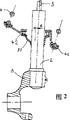
The strut comprises a ball bearing 42 located below the lower retainer 41 of the spring 4. The ball bearing 42 is centered on an eccentric collar 27 in order to shift the center of the ball bearing 42 by a distance e from the axis of the shock absorber. Rotation between the body 2 of the shock absorber and the hub holder 5 displaces the center of the ball bearing 42, which shifts the lower retainer 41 accordingly. Using a suitable measuring bench, the strut is adjusted precisely upon the assembling thereof.
Description
The present invention relates to McPpherson (Macpherson) formula suspension.Fig. 1 represents this suspension.The suspension of known this pattern comprises the pillar 1 that forms bumper basically, and described bumper also is the part of wheel flutter simultaneously.
Bumper comprises main body 2 and bar 3.The upper end 30 of bar depends on vehicle body by a point of connection 31, generally is the resilient connection joint.Helical spring 4 is installed between top race 40 and the bottom race 41.Bottom race 41 depends on the main body 2 of bumper, and top race 40 depends on vehicle body, generally also passes through the filtration in described elastic coupling joint, and in some cases, for spring and bumper, this filtration can be identical.
Have, main body 2 firmly is assemblied on the hub seat 5 again.So between main body 2 and hub seat 5, do not have degree of freedom.One side of underarm 6 and vehicle body connect, and opposite side is bound up on the hub seat 5 by connecting joint 65.Hub seat 5 is supported wheel hub 50, and the wheel flutter 51 of belt wheel tire 52 is housed on the wheel hub 50.
At the main body near zone, 1 pair of main body of shock structure applies from spring with from the power of bumper.Though determine that accurately the point of action of these power is difficult, particularly relevant, but know with the special construction of shock structure 1, for the correct working condition of the suspension of this pattern, grasp the suffered shearing force of bar 3 of bumper, have decisive action.In order to simulate McPpherson (Macpherson) formula suspension, can consider that vehicle body is R to the antagonistic force of shock structure.Its direction is that underarm 6 is applied to power B and the with joint efforts crossplot point of S of ground effects on tire 52 that connects on the joint 65 through some C and put C.In first approximation, vehicle is static, and the described S that makes a concerted effort is the center (when vehicle travelled in the straight line speed stabilizing, the numerical value of this power depended on the characteristic of tire and the adjustment situation of front axle geometrical property) of vertical direction and process tire contact zone.The intersection of B and S provides the C point.The shearing force T that direction on the thrust P that antagonistic force R is decomposed into spring and the bar 3 that acts on bumper and described bar 3 are vertical is so the relational expression that is suitable for is R=T+P (vectorial sum).
In order to obtain shock structure good work status (not having or very little dry friction minimum wearing and tearing or the like),, be considered to favourable to being applied to the in addition strict control of shearing force T on the bar 3.For this purpose, proposed to make of the axle inclination of the axle of spring 4, as shown in drawings with respect to bar 3.Therefore, the spring of in fact current used all McPpherson formula suspensions, its axle are not same with the axle of absorber rod.For reducing the shearing force on the bar 3, the angle of inclination of this spring 4 is calculated.
Have, applicant's research shows again: making a concerted effort of these power that spring applied, can apply a moment Cp around steering shaft, and described steering shaft is to be determined by the center 66 in point of connection 31 and connection joint 65.This torque is influential to stablizing of steering swivel system.In order to make steering swivel system that good work status be arranged, be necessary suitably to control and (for example reduce, from the compound influence of the torque Cp of left suspension and right suspension.
Unfortunately, various vehicles have only more coarse suspension and/or turning efficiency so far.The dynamic property of vehicle depends on a large amount of parameters, wherein has the influence of some parameters to know seldom especially, but is very important.Even consequently the designer gives one's full attention to whole specifications when the design suspension, its result may not embody the contribution in the design.
The present invention proposes some means, can make each car optimization in fact in the volume vehicle.In fact have been found that all parts of suspension, shock structure more precisely, the dispersiveness aspect characteristic is inevitably, this dispersiveness can cause between a car and another car bigger difference on the performance.The present invention proposes the required part of optimization, and makes between the thrust P and the shearing force T on the bar 3 of spring 4, the distribution method for optimizing around the torque Cp that turns to that the distribution of antagonistic force R and spring apply.
The present invention proposes, by remaining shearing force T method for optimizing preliminary evaluation is come out, for example remaining shearing force is as much as possible little for spring in shock structure, its degree of dip, adopt some parts, made and to have adjusted this remaining shearing force T or torque Cp more subtly.In this way, just might consider the dispersiveness of the dispersiveness, particularly spring performance of characteristic, the major cause that it seemingly causes the actual shearing force T of vehicle and torque Cp in batch to disperse very much.
The objective of the invention is, controlling spring is to the center of the thrust of top race and bottom race, direction with described thrust, and can not have influence on the common geom parameter of suspension, these parameters are wheel side inclination angles, the kingpin caster angle of steering shaft leaning angle and vehicle front wheel knuckle pin, these all remain unchanged.
The present invention proposes the shock structure of a kind of McPpherson (MacPherson) formula wheel suspension for McPpherson formula suspension, comprise the bumper that is provided with main body and bar, described shock structure comprises the spiral spring around described bar, it has a bottom race that is bearing on the absorber main body, described bottom race has one following, admit an end of described spring, also has a top race, preparation is placed in vehicle body, described top race has a seat of honour, admit the other end of described spring, described top race is run through by described bar, absorber main body has a surface, be used for joining hub seat to by coupling device, described hub seat is determined the S. A. of described wheel, and the preset bearing between described coupling device domination main body and the hub seat is characterized in that: described shock structure has and is used to adjust the axis of spring with respect to the relative position on described absorber main body surface and the device of keeping described adjustment position at the shock structure on period.
In addition, the invention allows for the shock structure of a kind of McPpherson (MacPherson) formula wheel suspension, comprise the bumper that is provided with main body and bar, described shock structure comprises the spiral spring around described bar, it has a bottom race that is bearing on the absorber main body, described bottom race has one following, admit an end of described spring, also has a top race, preparation is placed in vehicle body, described top race has a seat of honour, admit the other end of described spring, described top race is run through by described bar, and absorber main body has a surface, is used for joining hub seat to by coupling device, described hub seat is determined the S. A. of described wheel, it is characterized in that: one among the described seat of honour and following comprises that ball bearing of main shaft rotates to allow hub seat, the axle and the steering shaft space of described ball bearing of main shaft, and have be used to adjust described ball bearing of main shaft spool and steering shaft between distance and at the device of keeping described adjusting travel at the shock structure on period.
In addition, the invention allows for a kind of test desk that is used for the shock structure of above-mentioned McPpherson (MacPherson) formula suspension, described shock structure comprises :-bumper, comprise main body and bar, and described main body comprises the face of joint of preparing to install on the hub seat;-prepare to install to the coupling compoonent on the vehicle body, this member holds described bar, and is its formation elastic coupling joint;-around the spiral spring of bar;-being installed in the bottom race on the absorber main body and being installed in top race on the described coupling compoonent, described spring is inserted between the described seat ring; Described test desk comprises :-framework;-the first block of plate is equipped with the device that engages coupling compoonent on its face;-axle is suitable for use in and holds described main body;-ensure that axle is towards the device of doing relative motion with deviating from plate;-architectural device between the frame-saw of test desk and first block of plate is used for when being installed on the vehicle of preparing to receive described shock structure the stress of simulation shock structure;-be used to guarantee to obtain at least a device of representing the parameter value of the suffered stress of coupling compoonent; Described shock structure comprises that also one adjusts the axis of spring with respect to the relative position on described absorber main body surface and the device of keeping described adjustment position at the shock structure on period according to measured parameter value.
In addition, the invention allows for a kind of shock structure that is used to measure above-mentioned McPpherson (MacPherson) formula suspension device, it is formed by combining according to the above-mentioned test desk test desk identical with second.
By following description to an example, and with reference to the accompanying drawings, the present invention will be understood better, and the example of being given is with picture specification and be not limited to this, wherein:
Fig. 1 represents McPpherson (Macpherson) formula suspension;
Fig. 2 to 4 and Fig. 8 to 12 explanation bottom race are with respect to the axial translation of absorber rod, formed accentric adjustment;
Fig. 5 to 7 and the adjustment of Figure 13 to 15 explanation bevelled, bottom race is done various inclinations with respect to the direction of absorber rod;
Figure 16 and 17 explanation seat rings are to the adjustment of the different geometries of spring-loaded;
Figure 18 to 21 explanation bottom race is with respect to the translation adjustment of absorber rod axle;
Figure 22,23 and 24 explanations are according to three kinds of test desks of the present invention;
Figure 25 illustrates a two test desk, is the distinctive aspect of the present invention;
The McPpherson formula suspension that Figure 26 and 27 expression wheel flutters are used, front elevation and lateral plan;
Figure 28 and 29 has the main shaft of showing and the main force with scheme drawing;
Figure 30, a kind of possible adjustment situation of 31 and 32 explanations;
The equipment of Figure 33 and the automatically controlled adjustment usefulness of 34 explanations.
Fig. 2 to 7 describes shock structure, and used method of adjustment is that the main body 2 of bumper is done rotation relatively with respect to hub seat 5.Comprise to the coupling device of hub seat indicating mechanism (just with reference to mechanism), be used for the relative orientation of absorber main body with respect to hub seat, described sign mechanism be set at composition surface near.For example, it has a scale area, can indicate and change the relative position between main body 2 and the hub seat 5.Therefore, can control the relative angular position and/or the eccentric throw of bottom race.
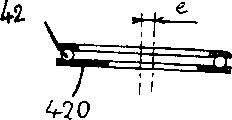
Before the setting device shown in below describing, we point out a bit: with regard to wheel flutter, shock structure comprises ball bearing of main shaft 42, at Fig. 2, and 5,6,8, to 14,22, can see in 23 and 26 to 30, its objective is the obstruction that makes turning to of wheel not be subjected to spring 4.
Ball bearing of main shaft 42 is arranged in the shock structure below the bottom race 41 of spring 4, and ball bearing of main shaft 42 is positioned the center of excentric sleeve 27, and there is a side-play amount e (Fig. 2 to 4) at the center that makes ball bearing of main shaft 42 with respect to the axle of bumper 2.Comparison diagram 3 and 4 as can be seen, absorber main body 2 can make the center displacement of ball bearing of main shaft 42 with respect to angle ε of hub seat 5 rotation, therefore makes bottom race 41 displacements.
The shock structure that Fig. 5 is represented, ball bearing of main shaft 42 also be arranged on bottom race 41 below, ball bearing of main shaft 42 is bevelleds, so the perpendicular line of bottom race areal of support forms a α angle with respect to the axis of bar 3.What Fig. 6 represented is: because main body 2 is rotated with respect to hub seat 5, the axle of ball bearing of main shaft 42 and the attitude of the spring on bottom race 41 4 change to some extent.Eccentric distance e and inclined angle alpha also can be united utilization.
In rear axle shock structure or front axle shock structure, ball bearing of main shaft 42 is arranged under the situation above the top race of spring (Fig. 7), and the bottom race 41 of spring 4 is an integral body with the main body 2 of bumper.The axle of bottom race 41 to be with respect to the axle of the absorber main body 2 β angle that tilts, and/or with respect to the axle of absorber main body 2 eccentric distance e arranged.Here, also can adjust the angle orientation of absorber main body 2 with respect to hub seat 5, the variation of described angle orientation can change the position of bottom race 41 with respect to top race, thereby adjusts the direction of the thrust of spring 4.
The adjustment of the eccentric rotation of Fig. 8 to 12 explanation: bottom race 41 is installed on the absorber main body 2 by the adjustable eccentric 420 of rotation.Eccentric 420 can be the part (Figure 10 and 12) of ball bearing of main shaft 42, perhaps is independent of ball bearing of main shaft (Fig. 8,9 and 11).Eccentric 420 rotates (Fig. 8 and 9) with respect to main body 2, or with respect to seat ring 41 rotations (Figure 11), makes seat ring 41 with respect to main body 2 displacements.Also can top race be installed on the main body by having the coupling compoonent of eccentric.
Figure 13 and 14 is represented to adjust with wedge, this wedge has a maximum ga(u)ge cross section and a radially relative minimum thickness cross section, thickness changes between described cross section continuously, described wedge 71 is with the described bottom race of one surface bearing, in addition, use counterrotating method, can adjust described wedge 71.This set is used to ball bearing of main shaft 42 for example and is contained in the front axle shock structure below the bottom race 41.Certainly, such as described, use wedge supporting top race (not shown) also can work to top race as wedge 71.
Figure 16 illustrates that a ring 78 forms supporting member, is contained in spring 4 and seat ring, here is between the bottom race 41.Described ring 78 forms the seat of a seat ring, be contained in described seat ring 41 around, can do on every side to rotate to move described, described ring forms a supporting member between spring and described seat ring, the recline face of seat ring of described ring is a plane of rotation, described ring has a maximum ga(u)ge cross section and a minimum thickness cross section, and green phase relatively rotates for described seat ring, and described ring can be adjusted.In Figure 17, expression be a kind of distortion, wherein, ring is 79 except variable thickness, it is accentric with respect to the abutment face with seat ring 41 that a seat is arranged, described abutment face is a plane of rotation.In both cases, by encircling 78 or 79, do not have and relatively move, implement to adjust with this and be bearing in spring on the ring with respect to seat ring 41 rotation.If spring allows, the eccentric characteristic of ring also can be independent of the feature of variation in thickness and be used.
At no steering shaft, or the steering shaft upper ball bearing is to be contained under the situation of the shock structure (Figure 18 to 21) above the spring top race, shock structure also can use described method of adjustment, mainly comprise following configuration: bottom race 41 is placed in the main body 2 of bumper to be formed on the axle sleeve 21 of one, described axle sleeve forms ways, guide the translation on the plane that intersects with damper shaft of described seat ring, described shock structure member is provided with mechanism, be used to select the relative position of described bottom race, and be used for described bottom race of locking and described axle sleeve on selected position with respect to described axle sleeve.
In described example, the relative translation between bottom race 41 and the axle sleeve 21 is to carry out on the vertical direction on the plane of Figure 19 to 21.Two of axle sleeve 21 are parallel and opposed edges is provided with tooth 22, and this tooth forms ways (Figure 18 and 19).The tooth on both sides guarantees to guide bottom race 41 translations (by described parallel edge), and this locks on relative position by tooth.
Above-mentioned adjustment element in any method of inspection of vehicle performance deviation, certainly is used for calibration.They can act on separately, wherein some use that also can be bonded to each other.The present invention can be looked after the severe tight tolerance that is contained in the shock structure actual behavior on the vehicle.Adjusting element can use in conjunction with measuring, for example to being added in the shearing force measurement on the bar, its method for example makes the top of bar separate from top race, or more generally the coupling component on the main body is separately, the top that is measured as the maintenance bar is perhaps measured with any suitable method in the required power of original shape.If wish to detect the combined effect of torque, be appropriate to the performance measurement of steering swivel system, so that adjust adjusting element, for example to for keeping vehicle straight-line travelling on given slope, and the torque that is applied on the wheel flutter is measured.Therefore, there are several parameters to measure, for example, the shearing force on the bar, around the rotating torque of steering shaft, or the torque on the wheel flutter, or relevant in the actual use of vehicle with the shock structure operation, representational other direct or indirect parameters.
Therefore, the terminal that can be desirably in manufacturing line is carried out meticulous adjustment.The method of service test is observed the effect of adjusting more, for example each car that shock structure of the present invention is housed is summed up as an experience card, sets up the calibration rule thus.These rules can supply the expert of drive system to be used for vehicle is adjusted in maintenance process especially.
According to another aspect of the present invention, propose in manufacturing process, before being installed on the vehicle, shock structure to be carried out work.Shearing force T and/or torque Cp are measured, as they on the vehicle of shock structure dress in, can on shock structure, show like that.This measurement can be finished on the fabricate block of shock structure.By a kind of device as described below, this measurement can be carried out under the favorable industrial condition, and the characteristic that the structure of described device is controlled as with the vehicle of adorning described shock structure becomes.According to the result who measures, spring is added in the device that the direction of the power of top race is adjusted, a direct acting is to adjusting the blocked corresponding part of element.
Figure 22,23 and 24 is illustrated as the shock structure of McPpherson suspension and the test desk established, and described shock structure comprises:
--prepare to install to the face of joint on the hub seat;
--prepare to be contained in the coupling compoonent on the vehicle body, accept described bar and be its elastic coupling joint of formation;
--around the spiral spring of described bar;
--be contained in the bottom race on the absorber main body and be contained in top race on the described coupling compoonent, described spring is inserted between the described seat ring;
--described test desk comprises and is contained on the framework:
--plate, it simultaneously is furnished with the device that is used to engage coupling compoonent;
--prepare to accept the axle of described main body;
--with axle towards plate or deviate from plate and mobile device;
--the test desk architectural device is used to that test desk is become and is equipped with the feature operation platform of the vehicle of described shock structure;
--be used for measuring at least a device of representing the stress value on the coupling compoonent.
In a certain embodiments (Figure 22), plate 90 is by first group of three connecting rod B1, B2, B3, be installed on the framework 92, mode with ball and socket or Equivalent Elasticity decoupling is installed, and is favourable to measuring like this, promptly do not introduce friction, connecting rod is contained in the surface of plate 90 on the one hand, with accept the surperficial relative of described coupling compoonent, be contained on the framework 92 relative, simultaneously at shapable recess on the other hand with plate 90, use the connecting rod B4 of second group of three coplane, B5, B6 is contained on the described plate face with ball and socket on the one hand, be contained on the other hand on the described framework, make the axis of their plane perpendicular to bar, at least one connecting rod in the described connecting rod comprises a stretching and compressive force sensor (I).Second group of B4 preferably, B5, at least two connecting rods among the B6, perhaps whole three connecting rods are equipped with this sensor I.This test desk might be under the condition near actual conditions, the actual stress of simulation shock structure.For this purpose, with three connecting rod B1, B2, B3 is linked to the E point together and suits.
If wish to measure shearing force T, the desired positions that E is ordered is: when shock structure installs on the car, on the space for shock structure, the position that is determined corresponding to the C point.If wish to measure torque Cp, the desired positions that E order is: when shock structure installs on the car, on the space for shock structure, corresponding to putting 66 positions that are determined.In both cases, measurement can obtain good being similar to, and needn't adjust test desk, that is to say, can carry out two kinds of measurements with a kind of configuration of test desk, as long as test desk is adjusted like this: be about to the E point location on the line segment of connection 66 to C.
In any case, the E point is that complete geometrical property from relevant vehicle draws.The reader is with reference to the preface part of this explanation, and point out the there: where some C and 66 is defined in, and that is and the definite shape of hub seat, connect joint 65, and the size of tire is relevant.The adjustment of test desk is undertaken by machinery, and it can make recessed part move, otherwise test desk can insert test desk apace by means of many casings of adjusting in advance, for example engages with clamp, and each casing is corresponding to a kind of vehicle.
Shock structure is assembling in advance.But, when it is measured on test desk, require the bar of bumper not connect with top race.All are prepared to be contained in shock structure on the main body by top race, and (or taking apart) do not assembled in the end of bar, and bar is pushed main body, and this is just enough.Be contained at top race under the situation of end of bar, feasible is, an adapter part identical shaped with the top of bar is provided, so that shock structure can be installed on the test desk, and the bar of bumper is not stressed, and is pushed the main body of people's bumper.
Shock structure is installed on the plate 90 by its top race 40 (or by adapter part), accurately is installed on the vehicle body as it, in other words, in this way installs: promptly the elastic coupling of absorber rod (point 31) is defined in suitable place.The method that main body 2 usefulness of bumper are inserted is installed on the axle 91.Test desk makes and spring 4 might be compressed to such position: i.e. its due position under the vehicle action of gravity, and this compression method is that axle 91 is done relative motion to plate 90, the axis that is parallel to bumper moves.
Measure then, particularly shearing force is measured.By the suitable processing of signal that one or several sensor is sent here, can obtain acting on the visual reading of power on the point 31 on plate 90 planes.This be the hypothesis bar be anchored on shock structure tighten firmware the time, the shearing force that should be subjected to.Sensor I on the connecting rod B5 if a sensor is provided on the connecting rod B5, also can measure the torque that is applied when a little 31 axis pushes spring 4 around extending to from an E.
The result of these measurements makes and might do meticulous adjustment to the thrust direction of spring, that is to say, by added adjustment element on the shock structure is applied effect, comes calibration vector P.Shearing force on this just possible correcting lever, or any other component of force that coupling compoonent applied on the plate 90.When desirable numerical value obtained, it was locked to adjust element, and shock structure can be with on the vehicle, and be sure of that in fact its elasticity and steering capability are in optimum value.
Figure 23 represents another test desk embodiment, wherein, plate 90 is by the plate P3 by the axle assembling, be installed on the framework 92, plate P3 is contained on the described plate 90 on the one hand and is connected with on the surperficial facing surfaces of described coupling compoonent, be contained on the other hand on the framework 92 (configurable axle) relative with described plate 90 (axle or equivalent spring bar), in addition, connecting rod B3, form one with the determined level crossing of plate P3 in the axis of E, connecting rod B3 on the one hand is contained in described plate and the surperficial facing surfaces that is connected with described coupling compoonent with ball and socket, is contained on the framework 92 relative with described plate 90 at configurable recess on the other hand, state determining of recess and described configurable shaft position, in fact constitute described configuration means, in addition, second connecting rod B4, be contained on the described plate 90 with ball and socket on the one hand, be contained on the other hand on the described framework 92, cause the axis of second connecting rod of institute's art perpendicular to bar, described second connecting rod has a stretching and compressive force sensor I.The test desk of having narrated above the configuration of this test desk is similar to, and be used by identical rule.
Figure 24 represents another variant embodiment of test desk, and wherein, plate 90 comprises a column 900 that is arranged essentially parallel to shock structure.This column is installed on the framework by two connecting rod B1 and B2, and connecting rod B1 and B2 for the shock structure that will measure, are set on the lower suspension triangle projective planum and (see the arm 6 of Fig. 1).Connecting rod B1 and B2 converge at the D point, with the geom beam-focusing of point 66 (Fig. 1 is seen at the center of the ball and socket 65 of arm 6).Plate 90 also is installed on the framework 92 by connecting rod B3, and connecting rod B3 is arranged on the wheel plane, along the direction of load S-.The axis of connecting rod B3 is through the C point.Plate 90 also is installed on the framework 92 by connecting rod B4 and B6, and connecting rod B4 and B6 are arranged on the plane perpendicular to the bumper axis, and they are orthogonal and converge at a little 31.Plate 90 also is installed on the framework by connecting rod B5, and connecting rod B5 is parallel with connecting rod B6.The plane that connecting rod B5 and B6 are determined, perpendicular to steer axis 80, and with this axes intersect in the point 31.Connecting rod B3, B4, B5 and B6 are equipped with sensor I.The bar of bumper does not connect with seat ring 40, and spring is compressed as can being compressed under normal load.This test desk has following several use: B4 directly measures the cross shear of absorber rod, B5 and B6 measure the longitudinal shear power of absorber rod, the torque that the B5 measuring spring is produced around steering shaft 80, B3 measures the vertical load of seeing from pivoted wheels on vehicle under the length of spring compressed state.The test desk shape that has illustrated above the shape of test desk is similar to has influence on the grappling of the different connecting rods of framework.
Therefore, this test desk, the two connecting rod B1 and the B2 that comprise first group of coplane, and the axle consistent with steering shaft 80 arranged, basically at the center of underarm ball and socket, test desk also comprises the two connecting rod B4 and the B6 of second group of coplane, its method to set up is to make the plane at their places perpendicular to the bar axle, is in the height in the described elastic coupling joint that holds described bar, test desk also comprises a connecting rod B5, with the B6 coplane, thereby make connecting rod B5 and the formed plane of B6, and on the height in described elastic coupling joint, intersect with described steering shaft perpendicular to steering shaft 80, also have a connecting rod B3, be positioned on the central plane of wheel.
Further, also may adopt a kind of test desk, have two measuring systems as described above, this just may be accepted as the right shock structure and the left shock structure of same vehicle design.The advantage of this test desk is: can be under condition extremely near actual conditions, and the suitable processing by to the sensor signal of two measuring systems just may obtain the visual reading of these two shock structures to the combined effect that wheel steering system produced.The result of these measurements makes and might adjust the synergy of two shock structures to steering swivel system subtly by the effect of the adjustment element on each post of these two shock structures.
An example of this adjustment platform as shown in figure 25.After adjusting, these two shock structure pairings, and be installed on the car.As can be seen, two positions all with narrated just now the same, all have plate 90 and axle 91 on each position.Connecting rod B1, B2, B3 are adjusted to and converge at an E, and are selected as becoming with the geometrical property of this vehicle that will equip shock structure.Some connecting rod is furnished with above-mentioned tensile/compressive forces sensor.Two axles 91 are installed in can be on the crossbeam 94 that slides on the framework 92, and crossbeam 94 slides at cylinder/piston effect lower edge framework.In this way, test desk just may compress the spring of each pillar component simultaneously.
The present invention also proposes the special adaptation method of steering swivel system, utilizes Figure 26 to 34 to be illustrated.Do in the process of divertical motion at wheel, under the actuating of the steering swivel system that is linked in hub seat 5 by connecting rod 53 with ball and socket, by shock structure, hub seat, the fabricate block that wheel hub and wheel are formed is around being rotated by point 31 and point 66 steering shafts that determined 80.
As seeing in all cases, S. A. 70 is different with steering shaft 80 usually.In all known embodiment, these two axles intersect.In fact, the axle of ball bearing of main shaft is equal to the common axis of bar 3 and absorber main body 2 usually.This structure, make might torque-limiting Cp effect, and torque Cp to be the thrust P of spring apply around steering shaft 80, and have influence on the stable of steering swivel system by connecting rod 53.
Although all these design trial, cause the attention of chaufeur to further improvement performance, be that not only vehicle structure is very reliable, and vehicle should be able to be driven cosily, the turning efficiency of many vehicles is still relatively poor so far.This driving performance in fact depends on many parameters, and the influence of some of them parameter is known little, and unfortunately they may be important.This result is exactly: though the designer has followed all specifications when calculating the steering swivel system scantling of structure, and the such equal effect that the result does not always obtain and has been noted that when designing.
Proposed by the invention, it is the development of shock structure design-calculated, this just might control and adjust more subtly the influence by the torque Cp that centers on steering shaft 80 that thrust produced of spring, thereby just might control shock structure the steering swivel system performance is total to the effect of load, and needn't do further to revise the geom character (feature angle and skew) of preceding axle system.So this invention provides additional Design freedom for the designer of suspension, it is irrelevant with the parameter that will consider in the definition of front axle traditionally fully.This additional design parameters further provides the ability of adjustment, the adjustment of shock structure is become than being easier to, and therefore shorten the development process of following vehicle suspension.
Shock structure according to McPpherson formula wheel suspension of the present invention, a described shock structure of bumper that comprises main body and bar is arranged, spiral spring around described bar is arranged, bottom race by the absorber main body supporting is arranged, described bottom race has following of accepting described spring one end, also has a predetermined top race that is bound up on the vehicle body, described top race has a seat of honour of accepting the described spring other end, described top race is run through by described bar, absorber main body has a surface to engage hub seat with coupling device, described hub seat determines the S. A. of described wheel, in top race and the bottom race one, comprise a ball bearing of main shaft, turn to allow hub seat, it is characterized in that: the axle and the steering shaft of described ball bearing of main shaft are not axles.
Therefore the present invention proposes the shock structure that a kind of McPpherson formula wheel flutter suspension is used, and wherein, the localization method of the S. A. of ball bearing of main shaft 42 is not intersect with steering shaft 80.So this S. A. both can be parallel with steering shaft, also can with steering shaft coplane not.Then just might be in both cases, determine between two axles apart from d.This is a minor increment between detectable two the relevant points of these two axles apart from d.Under the situation on ball bearing of main shaft 42 is contained in top race 40, as shown in Figure 27 or 29, this distance with each all vertical direction on be determined.
Since be a kind of like this structure, just might be to the thrust of spring
 The torque Cp that is applied around steering
 shaft 80 controls, as narration below and with Figure 28 and 29 explanations.Therefore, two the torque Cp that shock structure produced by the right side and the left side cooperate with steering swivel system under the perfect control method.
Spring applies a tool thrust to bottom race 41
 This thrust
Through ball bearing of main shaft 42.The internal friction of this ball bearing of
This thrust
Through ball bearing of main shaft 42.The internal friction of this ball bearing of main shaft 42 is very little, under these conditions, and the thrust of spring
 Axle
Axle 70 added moment of rotation along bearing are zero.This zero moment is due to the fact that: the thrust of spring
Direction and ball bearing of main shaft 42 the axle intersect at the B point, as shown in Figure 28 and 29.If because the adjustment of shock structure, from the thrust of a B
Sensing not with steering shaft 80 intersections, the consequently thrust of spring
Apply a torque Cp around steering shaft 80, this torque is proportional to the described thrust of spring
Perpendicular to the component of steering shaft 80, and foregoing apart from d.The perfect control of the direction of d and the power of adjusting the distance just might provide very accurate torque Cp value.
This can determine in the design of shock structure apart from d, so the torque Cp of shock structure that can control the right side and the left side is to the effect of steering swivel system.
According to another aspect of the present invention, this can be adjusted apart from d.No matter in this case, just become the torque synergy that might regulate two shock structures, so that proofread and correct any defective on the steering swivel system performance of finding onboard, be any method of inspection.Therefore, people can carry out described adjustment in the terminal of assigned line, perhaps, more be experienced, by observing the influence of described adjustment, for example, by means of the experience card of each car that shock structure of the present invention is housed, thereby set up the correction standard that some use for the brainstrust of drive system aspect.Therefore, this adjustment can be utilized, and particularly in the maintenance process of vehicle, is used for turning efficiency is carried out possible correction.Because test desk energy measurement torque Cp, so, also just may in the assembling process of shock structure, adjust.For example, can use in the above-mentioned test desk one.Figure 27, the eccentric ball bearing of main shaft 42 of 30 to 32 explanations.By relatively rotating of the wedge on the supporter that is contained in the direct contact vehicle body 72, to adjust, described wedge 72 has a recess to admit ball bearing of main shaft 42.For example, as can be seen, the axle of the thrust baring among Figure 31 is apart from steering shaft farther than shown in Figure 30.In this example, adjustment is at the automotive servicing station or on test desk, when shock structure is installed, and the operation of being carried out.
Can show as the translation of thrust baring apart from the method for adjustment of d, and not change the orientation of axle, for example, the ring 74 of going up of the thrust baring 42 that is eccentric in absorber rod 3 be adjusted (Figure 30 to 34).This adjustment decides with such method: it will change the thrust performance of spring, and particularly its rigidity is as much as possible little.Therefore, the translation of thrust baring will be preferentially be carried out along the plane of closing perpendicular to the geometrical axis of spring, and its inclination, will around preferably with the geometrical axis of spring intersect spool.
In a single day also can in the vehicle ' process, adjust apart from d,, immediately this defective be proofreaied and correct so that find the defective of turning efficiency.This defective may be noticed by the chaufeur of vehicle.In this case, this correction of being undertaken by adjusting travel d can utilize by the actuating unit of vehicle driver control itself and realize.The detection of defective also can automatically be carried out, and for example torque is measured, and described torque is need be added on the wheel flutter for the rectilinear orbit that keeps vehicle.In this case, can be controlled by full automatic active correction system apart from the adjustment of d.
Figure 33 and 34 one of expression comprise the embodiment that can change apart from the mechanization system of d.Ball holds 42 go up on the lining that ring 74 is mounted on low friction.These ring 74 quilts are handled around axle 73 rotations perpendicular to described plane of a loop, and are located in its periphery a bit, and in addition, this ring comprises and the relative tooth bar 75 of described axle that this tooth bar 75 is actuated by the miniature gears 76 of the axle that is linked in electric-controlled mechanical system 77.This mechanization system 77 has a kind of irreversible property, in other words, is not having under the situation of feed voltage, be added in miniature gears 76 the axle on torque, can not make its rotation.This motorisation unit can be realized, for example, utilizes the electric notor that is connected with retarder such as endless screw system, perhaps utilizes the piezoelectric type motor of direct drive miniature gears 76 to realize.
Claims (16)
1, the shock structure of McPpherson (MacPherson) formula wheel suspension, comprise the bumper that is provided with main body (2) and bar (3), described shock structure comprises the spiral spring (4) around described bar (3), it has a bottom race (41) that is bearing on the absorber main body (2), described bottom race has one following, admit an end of described spring, also has a top race (40), preparation is placed in vehicle body, described top race has a seat of honour, admit the other end of described spring, described top race is run through by described bar, absorber main body has a surface, be used for joining hub seat (5) to by coupling device, described hub seat is determined the S. A. of described wheel, and the preset bearing between described coupling device domination main body and the hub seat is characterized in that: described shock structure has and is used to adjust the axis of spring with respect to the relative position on described absorber main body surface and the device of keeping described adjustment position at the shock structure on period.
2, according to the shock structure of claim 1, it is characterized in that: wherein, described adjustment and adjustment holdout device consist essentially of following arrangement: described bottom race is installed on the absorber main body by an eccentric (420), and the eccentric rotation is adjustable.
3, according to the shock structure of claim 1, it is characterized in that: wherein, described adjustment and adjust holdout device and consist essentially of following arrangement: one of seat ring is placed on the wedge (71) with a pair of surface, wedge comprises a maximum ga(u)ge cross section, with relative with this a cross section diametrically minimum thickness cross section, thickness changes between described cross section continuously, and described wedge supports described seat ring with one surface, and described wedge can be done rotation relatively and adjust.
4, according to the shock structure of claim 3, it is characterized in that: wherein, described seat ring is a bottom race, and described wedge (71) is accepted bottom race (41) with one surface, another surface of described wedge is installed on the supporting sleeve that is integrated with absorber main body.
5, according to the shock structure of claim 1, it is characterized in that: wherein, described adjustment and adjustment holdout device comprise a ring (78) that is used to form the seat of a seat ring, this ring be installed in described seat ring around, and can around described, rotatablely move, described ring forms a upholder that is used at described seat ring upper spring, the surface that described ring is attached on the seat ring is a plane of revolution, described ring has a maximum ga(u)ge cross section and a minimum thickness cross section, and described ring is adjustable with respect to described seat ring rotation.
6, according to the shock structure of claim 1, it is characterized in that: wherein, described adjustment and adjustment holdout device comprise a ring that forms eccentric (79), described ring forms the seat of a seat ring, and an attachment face is arranged, and being placed on the described seat ring, described ring is adjustable with respect to described seat ring rotation.
7, according to the shock structure of claim 1, it is characterized in that: wherein, described adjustment and adjustment holdout device comprise the device of sign absorber main body with respect to the relative direction of hub seat, by the rotation of described absorber main body with respect to hub seat, realize adjusting.
8, according to the shock structure of claim 1, it is characterized in that: wherein, described setting device consists essentially of following arrangement: bottom race (41) is placed on the axle sleeve (22) that is integrated with absorber main body (2), described axle sleeve forms a ways, guide the translation on the plane that intersects with damper shaft of described seat ring, described shock structure comprises: be used to select the device of described bottom race with respect to the relative position of described axle sleeve, and the device that on selected position, locks described bottom race and described axle sleeve.
9, the shock structure of McPpherson (MacPherson) formula wheel suspension, comprise the bumper that is provided with main body (2) and bar (3), described shock structure comprises the spiral spring (4) around described bar (3), it has a bottom race (41) that is bearing on the absorber main body (2), described bottom race has one following, admit an end of described spring, also has a top race (40), preparation is placed in vehicle body, described top race has a seat of honour, admit the other end of described spring, described top race is run through by described bar, absorber main body has a surface, be used for joining hub seat (5) to by coupling device, described hub seat is determined the S. A. of described wheel, it is characterized in that: one among the described seat of honour and following comprises that ball bearing of main shaft (42) is with the rotation of permission hub seat, the axle and steering shaft (80) space of described ball bearing of main shaft, and have the axle that is used to adjust described ball bearing of main shaft and the distance between the steering shaft (80) and at the device of keeping described adjusting travel at the shock structure on period.
10, according to the shock structure of claim 9, it is characterized in that: wherein, described adjustment and adjustment holdout device comprise the upward ring (74) of the ball bearing of main shaft (42) on the lining that is mounted on low friction, ring (74) is handled around axle (73) rotation perpendicular to described plane of a loop, and be located in its periphery a bit, and comprise and the relative tooth bar (75) of described axle that this tooth bar (75) is actuated by the miniature gears (76) of the axle that is linked in irreversible electric-controlled mechanical system (77).
11, a kind of test desk that is used for the shock structure of McPpherson as claimed in claim 1 (MacPherson) formula suspension, described shock structure comprises :-bumper, comprise main body and bar, described main body comprises the face of joint of preparing to install on the hub seat;-prepare to install to the coupling compoonent on the vehicle body, this member holds described bar, and is its formation elastic coupling joint; The spiral spring of-distaff;-being installed in the bottom race on the absorber main body and being installed in top race on the described coupling compoonent, described spring is inserted between the described seat ring;
-described test desk comprises:
-framework (92);
-the first block of plate (90) is equipped with the device that engages coupling compoonent on its face;
-axle (91) is suitable for use in and holds described main body;
-ensure that axle is towards the device of doing relative motion with deviating from plate;
-architectural device between the frame-saw of test desk and first block of plate is used for when being installed on the vehicle of preparing to receive described shock structure the stress of simulation shock structure;
-be used to guarantee to obtain at least a device of representing the parameter value of the suffered stress of coupling compoonent;
Described shock structure comprises that also one adjusts the axis of spring with respect to the relative position on described absorber main body surface and the device of keeping described adjustment position at the shock structure on period according to measured parameter value.
12, test desk according to claim 11, it is characterized in that: wherein, plate is by first group of three connecting rod (B1, B2 B3) is installed on the framework, the axle of these connecting rods, be contained on the one hand on the face of described first block of plate (90) with ball and socket simultaneously, relative one side is connected with described coupling compoonent, on the other hand at configurable recess, is contained in the face of on the framework (92) of described first block of plate, the location of described recess, become the configuration means in fact, simultaneously, plate is by the connecting rod (B4 of second group of three coplane, B5, B6) be installed on the framework, the axle of these connecting rods is contained on described first block of plate on the one hand with ball and socket, be contained on the other hand on the described framework, its bind mode is to make the axle of their plane perpendicular to bar, and at least one connecting rod in the described connecting rod comprises stretching and compressive force sensor.
13, according to the test desk of claim 12, it is characterized in that: wherein, at least two connecting rods in described second group of connecting rod comprise force gauge (I), so that measure the shearing force on the absorber rod.
14, test desk according to claim 11, it is characterized in that: wherein, first block of plate is installed on the framework by another piece plate (P3), described another piece plate, be contained on described first block of plate face relative by configurable axle on the one hand with the face that is associated with described coupling compoonent, be contained on the other hand in the face of on the framework of described first block of plate, first block of plate also is installed on the framework by connecting rod (B3), connecting rod (B3) is contained on described first block of plate face relative with the face that is associated with top race on the one hand with ball and socket, on the other hand at configurable recess, be contained in the face of on the framework of described first block of plate, the adjustment of described recess, become described configuration means in fact, first block of plate also is installed on the framework by second connecting rod (B4), and connecting rod (B4) is contained on described first block of plate on the one hand with ball and socket, is contained on the other hand on the described framework, so that described second connecting rod is perpendicular to the axle of bar, described second connecting rod comprises and stretches and the compressive force sensor.
15, test desk according to claim 11, it is characterized in that: wherein, plate (90) and joint pin (900) assembly, be contained on the framework (92) by six roots of sensation connecting rod (B1 to B6), these connecting rods are contained on the described assembly on the one hand with ball and socket, on the other hand at configurable recess, be contained in the face of on the framework of described assembly, wherein first group of two connecting rod (B1 and B2) are coplanes, the axle of coplane is consistent with steering shaft (80), basically at the joint center of the ball and socket of underarm, wherein second group of two connecting rod (B4 and B6) are coplanes, and arrange like this: make the axle of their plane, and be positioned on the height in the elastic coupling joint that holds described bar, wherein connecting rod (B5) and connecting rod (B6) coplane perpendicular to bar, other discharge method is: the plane that connecting rod (B5 and B6) forms is perpendicular to steering shaft (80), and on the height in described elastic coupling joint, intersect with described steering shaft, wherein connecting rod (B3) is positioned on the central plane of wheel.
16, a kind of shock structure that is used to measure McPpherson as claimed in claim 1 (MacPherson) formula suspension device, it is combined by the test desk according to claim 11 test desk identical with second and forms.
Applications Claiming Priority (4)
| Application Number | Priority Date | Filing Date | Title |
|---|---|---|---|
| FR9515891A FR2742381A1 (en) | 1995-12-19 | 1995-12-19 | Vehicle wheel McPherson=type suspension strut |
| FR9515891 | 1995-12-19 | ||
| FR9603921 | 1996-03-26 | ||
| FR9603921 | 1996-03-26 |
Publications (2)
| Publication Number | Publication Date |
|---|---|
| CN1157226A CN1157226A (en) | 1997-08-20 |
| CN1068835C true CN1068835C (en) | 2001-07-25 |
Family
ID=26232419
Family Applications (1)
| Application Number | Title | Priority Date | Filing Date |
|---|---|---|---|
| CN96114060A Expired - Fee Related CN1068835C (en) | 1995-12-19 | 1996-12-19 | Adjustment Means for shock-absorbing strut and measuring bench |
Country Status (7)
| Country | Link |
|---|---|
| US (2) | US5947459A (en) |
| EP (1) | EP0780250B1 (en) |
| JP (1) | JPH09220918A (en) |
| KR (1) | KR970034054A (en) |
| CN (1) | CN1068835C (en) |
| BR (1) | BR9606068A (en) |
| DE (1) | DE69627116T2 (en) |
Families Citing this family (50)
| Publication number | Priority date | Publication date | Assignee | Title |
|---|---|---|---|---|
| EP0780250B1 (en) * | 1995-12-19 | 2003-04-02 | COMPAGNIE GENERALE DES ETABLISSEMENTS MICHELIN-MICHELIN & CIE | Fine adjustment of a MacPherson suspension strut: means for adjusting on the strut and measuring bench |
| JPH1159155A (en) * | 1997-08-08 | 1999-03-02 | Chuo Spring Co Ltd | Compression coil spring inserted shock absorber |
| JPH11173355A (en) * | 1997-12-11 | 1999-06-29 | Showa Corp | Suspension device |
| DE19806829C1 (en) * | 1998-02-18 | 1999-08-19 | Btr Avs Technical Centre Gmbh | Upper spring plate structure for a suspension strut |
| US6079700A (en) * | 1998-10-09 | 2000-06-27 | Chrysler Corporation | Vehicle shock absorber spring seat pad having a spring--containment peripheral flange |
| FR2789944A1 (en) | 1999-02-19 | 2000-08-25 | Michelin & Cie | MacPherson-type wheel suspension strut has first spiral of spring capable of being fixed in different positions on lower cup |
| FR2790986A1 (en) | 1999-03-19 | 2000-09-22 | Michelin & Cie | METHOD AND DEVICE FOR PRECISE MOUNTING OF A MAC PHERSON SUSPENSION FORCE LEG |
| FR2791608A1 (en) | 1999-03-19 | 2000-10-06 | Michelin & Cie | MAC PHERSON SUSPENSION FORCE LEG AND ADJUSTMENT METHOD THEREOF |
| DE10036048B4 (en) * | 1999-08-18 | 2010-04-22 | Zf Sachs Ag | Suspension strut with a steering knuckle |
| FR2804376A1 (en) | 2000-02-01 | 2001-08-03 | Michelin Ets | COMPENSATION METHOD FOR DRAWING A VEHICLE EQUIPPED WITH MAC PHERSON SUSPENSION AND FORCE LEG FOR COMPENSATION |
| DE10023194B4 (en) * | 2000-05-11 | 2004-10-14 | Dr.Ing.H.C. F. Porsche Ag | Body structure for a motor vehicle with front strut mounts |
| US6382645B1 (en) | 2000-12-04 | 2002-05-07 | Northstar Manufacturing Co., Inc. | Offset upper strut mount |
| JP2002178736A (en) * | 2000-12-14 | 2002-06-26 | Chuo Spring Co Ltd | Suspension coiled spring for automobile and strut type suspension device equipped with the same |
| JP2002234324A (en) * | 2001-02-08 | 2002-08-20 | Chuo Spring Co Ltd | Automobile suspension coil spring and strut suspension system having the suspension coil spring |
| KR100397982B1 (en) * | 2001-02-21 | 2003-09-19 | 현대자동차주식회사 | Device for learning geometric characteristics of automotive suspension |
| NL1017842C2 (en) * | 2001-04-12 | 2002-10-15 | Skf Ab | Shock absorber module. |
| DE10238788B4 (en) * | 2002-08-23 | 2004-07-29 | Lehmann, Bernhard, Dr. | Optimization of the spring characteristic of a spring damper unit for a motor vehicle wheel suspension |
| US6773197B2 (en) * | 2002-10-09 | 2004-08-10 | Trw Inc. | Ball joint |
| FR2847516B1 (en) * | 2002-11-27 | 2005-01-28 | Roulements Soc Nouvelle | SUSPENDED SUSPENSION IN ROTATION TO MEASURE VERTICAL EFFORTS |
| FR2847515B1 (en) * | 2002-11-27 | 2006-07-14 | Roulements Soc Nouvelle | SUSPENSION OF INSTRUMENTED SUSPENSION IN DEFORMATION TO MEASURE EFFORTS |
| DE10258936A1 (en) * | 2002-12-17 | 2004-07-01 | Volkswagen Ag | Suspension strut for a motor vehicle wheel suspension |
| US6843472B2 (en) | 2003-01-21 | 2005-01-18 | The Pullman Company | Upper shock mount isolator with integral air spring housing pivot bearing |
| US20040169323A1 (en) * | 2003-02-28 | 2004-09-02 | Bottene Marlon V. | MacPherson strut spring coil mounts |
| US20040169324A1 (en) * | 2003-02-28 | 2004-09-02 | Bottene Marlon V. | Strut spring seat |
| JP3944907B2 (en) * | 2003-03-14 | 2007-07-18 | マツダ株式会社 | Front suspension device for automobile |
| US7117982B2 (en) * | 2003-06-13 | 2006-10-10 | Kayaba Industry Co., Ltd. | Shock absorber |
| JP4254599B2 (en) * | 2004-04-01 | 2009-04-15 | トヨタ自動車株式会社 | Strut suspension |
| DE102004024089B3 (en) * | 2004-05-14 | 2005-12-08 | Audi Ag | Bearing device for a spring arrangement |
| JP2006088962A (en) * | 2004-09-27 | 2006-04-06 | Toyota Motor Corp | Strut type suspension |
| DE102004058698B3 (en) * | 2004-12-06 | 2006-02-09 | Muhr Und Bender Kg | Adjustable spring wheel suspension for motor vehicle has coil spring arranged with force direction line deviating from geometrical center line of spring |
| DE102005032449A1 (en) * | 2005-07-12 | 2007-01-18 | Zf Friedrichshafen Ag | Spring plate Pad |
| JP4890013B2 (en) * | 2005-12-01 | 2012-03-07 | トヨタ自動車株式会社 | Strut suspension |
| US7677551B2 (en) * | 2006-03-15 | 2010-03-16 | Kyocera Mita Corporation | Document conveying apparatus |
| US7946163B2 (en) | 2007-04-02 | 2011-05-24 | Penske Racing Shocks | Methods and apparatus for developing a vehicle suspension |
| JP4577345B2 (en) | 2007-09-26 | 2010-11-10 | トヨタ自動車株式会社 | Knuckle and knuckle manufacturing method |
| DE102008006087A1 (en) * | 2008-01-25 | 2009-07-30 | Thyssenkrupp Bilstein Suspension Gmbh | Suspension strut with adjustable spring plate |
| DE102008024978B4 (en) * | 2008-05-23 | 2015-07-23 | Bayerische Motoren Werke Aktiengesellschaft | Suspension of a two-lane vehicle |
| DE102009022841B4 (en) * | 2009-05-27 | 2013-08-01 | Anvis Deutschland Gmbh | Elastic strut head bearing for a motor vehicle and method for adjusting a compression preload in an elastic ring body of the shock absorber head bearing |
| US8302980B2 (en) * | 2010-12-23 | 2012-11-06 | GM Global Technology Operations LLC | Eccentric steering axis strut top mount |
| US8696004B2 (en) * | 2011-12-08 | 2014-04-15 | Tenneco Automotive Operating Company Inc. | Spring seat having an installation land/step |
| US9458905B2 (en) * | 2012-09-20 | 2016-10-04 | Steelcase Inc. | Spring assembly and method |
| CN105163962B (en) * | 2013-04-30 | 2017-03-15 | 日产自动车株式会社 | In-wheel motor driving moment draft hitch |
| JP6240442B2 (en) * | 2013-09-06 | 2017-11-29 | 株式会社ショーワ | Spring seat |
| CN104913919B (en) * | 2015-06-16 | 2018-09-07 | 西华大学 | Rubber shock absorber dynamic and static state performance test device |
| JP6613095B2 (en) * | 2015-10-01 | 2019-11-27 | 日本発條株式会社 | Coil spring for suspension |
| JP6871707B2 (en) * | 2016-09-30 | 2021-05-12 | ヤマハ発動機株式会社 | Shock absorbers, vehicles, snow vehicles |
| CN110461629B (en) | 2017-01-19 | 2023-07-14 | 多夫泰克有限公司 | Electromechanical device for controlling a vehicle suspension arrangement |
| CN109520566B (en) * | 2018-11-23 | 2023-12-08 | 中国船舶重工集团公司第七一九研究所 | Vibration isolator capable of displaying stress and deformation |
| DE102019134789B4 (en) * | 2019-12-17 | 2021-07-01 | Audi Ag | Wheel suspension for a vehicle |
| CN112254944A (en) * | 2020-10-19 | 2021-01-22 | 奇瑞商用车(安徽)有限公司 | New energy automobile shock absorber assembly lower mounting bracket welding strength test device and test method |
Citations (2)
| Publication number | Priority date | Publication date | Assignee | Title |
|---|---|---|---|---|
| US3573880A (en) * | 1967-10-28 | 1971-04-06 | Nissan Motor | Front wheel suspension for motor vehicle |
| US4863187A (en) * | 1988-03-28 | 1989-09-05 | Artz William P | Camber adjustment device with finite camber adjustment settings |
Family Cites Families (15)
| Publication number | Priority date | Publication date | Assignee | Title |
|---|---|---|---|---|
| ZA706176B (en) * | 1969-11-13 | 1971-05-27 | Monroe Belgium Nv | Shock absorber testing apparatus |
| US3857276A (en) * | 1969-11-13 | 1974-12-31 | Monroe Belgium Nv | Shock absorber testing apparatus |
| SE377497B (en) * | 1973-01-17 | 1975-07-07 | R P S Graham | |
| DE2445406C2 (en) * | 1974-09-23 | 1980-02-14 | Gebr. Hofmann Gmbh & Co Kg, Maschinenfabrik, 6100 Darmstadt | Method and device for testing vibration dampers in a vehicle |
| US4026578A (en) * | 1976-04-07 | 1977-05-31 | Mattson Charles T | Vehicular wheel adjusting device |
| GB2100681B (en) * | 1981-06-19 | 1984-08-30 | Samefa Ag | Measuring apparatus for checking the spring strut of a vehicle front wheel suspension |
| US4424697A (en) * | 1981-09-25 | 1984-01-10 | Carver James L | Wheel mounting suspension strut camber correcting tool |
| IT1155316B (en) * | 1982-04-21 | 1987-01-28 | Fiat Auto Spa | SUSPENSION FOR A VEHICLE WHEEL |
| DE3312453C2 (en) * | 1983-04-07 | 1996-04-25 | Fichtel & Sachs Ag | Adjustable shock absorber |
| JPS62286816A (en) * | 1986-06-03 | 1987-12-12 | Nissan Motor Co Ltd | Suspension load detecting device |
| JPS6490807A (en) * | 1987-09-30 | 1989-04-07 | Mazda Motor | Strut type suspension of vehicle |
| FR2641741B1 (en) * | 1988-12-28 | 1991-05-03 | Peugeot | SUSPENSION DEVICE FOR MOTOR VEHICLE |
| AT393248B (en) * | 1990-02-01 | 1991-09-10 | Steyr Daimler Puch Ag | WHEEL SUSPENSION |
| US5942673A (en) * | 1996-05-24 | 1999-08-24 | Hitachi, Ltd. | Vehicle testing system and testing method |
| EP0780250B1 (en) * | 1995-12-19 | 2003-04-02 | COMPAGNIE GENERALE DES ETABLISSEMENTS MICHELIN-MICHELIN & CIE | Fine adjustment of a MacPherson suspension strut: means for adjusting on the strut and measuring bench |
-
1996
- 1996-12-05 EP EP96119526A patent/EP0780250B1/en not_active Expired - Lifetime
- 1996-12-05 DE DE69627116T patent/DE69627116T2/en not_active Expired - Fee Related
- 1996-12-18 KR KR1019960067177A patent/KR970034054A/en not_active Application Discontinuation
- 1996-12-18 BR BR9606068A patent/BR9606068A/en not_active IP Right Cessation
- 1996-12-18 US US08/769,713 patent/US5947459A/en not_active Expired - Fee Related
- 1996-12-19 JP JP8339908A patent/JPH09220918A/en active Pending
- 1996-12-19 CN CN96114060A patent/CN1068835C/en not_active Expired - Fee Related
-
1999
- 1999-06-08 US US09/327,988 patent/US6082720A/en not_active Expired - Fee Related
Patent Citations (2)
| Publication number | Priority date | Publication date | Assignee | Title |
|---|---|---|---|---|
| US3573880A (en) * | 1967-10-28 | 1971-04-06 | Nissan Motor | Front wheel suspension for motor vehicle |
| US4863187A (en) * | 1988-03-28 | 1989-09-05 | Artz William P | Camber adjustment device with finite camber adjustment settings |
Also Published As
| Publication number | Publication date |
|---|---|
| KR970034054A (en) | 1997-07-22 |
| MX9606484A (en) | 1998-06-30 |
| EP0780250A3 (en) | 1998-05-06 |
| DE69627116T2 (en) | 2003-12-24 |
| DE69627116D1 (en) | 2003-05-08 |
| EP0780250B1 (en) | 2003-04-02 |
| US5947459A (en) | 1999-09-07 |
| BR9606068A (en) | 1998-09-01 |
| CN1157226A (en) | 1997-08-20 |
| EP0780250A2 (en) | 1997-06-25 |
| JPH09220918A (en) | 1997-08-26 |
| US6082720A (en) | 2000-07-04 |
Similar Documents
| Publication | Publication Date | Title |
|---|---|---|
| CN1068835C (en) | Adjustment Means for shock-absorbing strut and measuring bench | |
| CN1189729C (en) | System for analyzing suspension system | |
| CN1055268C (en) | Self-stabilising directionally controllable vehicle with at least three wheels | |
| RU2517274C2 (en) | Independent suspension of transport facility | |
| CN103121387B (en) | MacPherson air suspension and assembly method thereof | |
| CN107639986B (en) | A kind of Swing Arm Type Balanced Suspension with flare angle adjusting mechanism | |
| CN206710079U (en) | A kind of automobile leaf spring torsional fatigue test device | |
| US20190283575A1 (en) | Floating differential suspension system | |
| US20090102152A1 (en) | Rear radius arm and rear radius arm mount for improved handling of factory and lifted large-scale suspension strokes and articulations for on and off road vehicles | |
| EP1459968B1 (en) | Rocking vehicle | |
| CN1241762C (en) | Zero roll suspension system | |
| CN104995118B (en) | Elevator machine actuating device | |
| CN1146514C (en) | Wiper arm | |
| DE10221993B4 (en) | Arm | |
| CN1894116A (en) | Determining a relative movement of a chassis and a body of a wheeled vehicle | |
| CN1672026A (en) | Position detection device and method for wheel inclination angle adjusting member | |
| CN1890132A (en) | Heavy vehicle | |
| DE202014100803U1 (en) | measuring device | |
| GB2528678A (en) | The fulcrum transport machine | |
| US7021414B2 (en) | Birdcage bearing assembly and suspension connection for a high performance vehicle | |
| KR20160125410A (en) | Couplable motor vehicle with improved coupling | |
| EP1980424A2 (en) | Vehicle suspension system | |
| CN210756575U (en) | Swing arm processing frock on car | |
| CN205575461U (en) | Car lifting devices is put in order to passenger train with adjustable | |
| KR100416516B1 (en) | The Camber And Caster Adjustment Apparatus of Car Suspension Using the Eccentricity of Adjustment Shaft |
Legal Events
| Date | Code | Title | Description |
|---|---|---|---|
| C06 | Publication | ||
| PB01 | Publication | ||
| C10 | Entry into substantive examination | ||
| SE01 | Entry into force of request for substantive examination | ||
| C14 | Grant of patent or utility model | ||
| GR01 | Patent grant | ||
| C19 | Lapse of patent right due to non-payment of the annual fee | ||
| CF01 | Termination of patent right due to non-payment of annual fee |