EP0779998B1 - Process for determining the position of a landmark in the map of the environment of an automotive unit which dynamically determines its distance from the landmark - Google Patents
Process for determining the position of a landmark in the map of the environment of an automotive unit which dynamically determines its distance from the landmark Download PDFInfo
- Publication number
- EP0779998B1 EP0779998B1 EP95929756A EP95929756A EP0779998B1 EP 0779998 B1 EP0779998 B1 EP 0779998B1 EP 95929756 A EP95929756 A EP 95929756A EP 95929756 A EP95929756 A EP 95929756A EP 0779998 B1 EP0779998 B1 EP 0779998B1
- Authority
- EP
- European Patent Office
- Prior art keywords
- landmark
- unit
- distance
- determined
- predicted
- Prior art date
- Legal status (The legal status is an assumption and is not a legal conclusion. Google has not performed a legal analysis and makes no representation as to the accuracy of the status listed.)
- Expired - Lifetime
Links
- 238000000034 method Methods 0.000 title claims description 38
- 238000005259 measurement Methods 0.000 claims description 27
- 239000011159 matrix material Substances 0.000 claims 2
- 230000004888 barrier function Effects 0.000 description 6
- 238000012937 correction Methods 0.000 description 5
- 238000010200 validation analysis Methods 0.000 description 4
- 238000013459 approach Methods 0.000 description 2
- 230000015572 biosynthetic process Effects 0.000 description 2
- 238000004364 calculation method Methods 0.000 description 1
- 230000015556 catabolic process Effects 0.000 description 1
- 238000007796 conventional method Methods 0.000 description 1
- 230000002596 correlated effect Effects 0.000 description 1
- 230000000875 corresponding effect Effects 0.000 description 1
- 230000001419 dependent effect Effects 0.000 description 1
- 238000011161 development Methods 0.000 description 1
- 230000018109 developmental process Effects 0.000 description 1
- 230000002349 favourable effect Effects 0.000 description 1
- 230000004807 localization Effects 0.000 description 1
- 238000004519 manufacturing process Methods 0.000 description 1
- 238000012545 processing Methods 0.000 description 1
- 239000000523 sample Substances 0.000 description 1
Images
Classifications
-
- G—PHYSICS
- G05—CONTROLLING; REGULATING
- G05D—SYSTEMS FOR CONTROLLING OR REGULATING NON-ELECTRIC VARIABLES
- G05D1/00—Control of position, course or altitude of land, water, air, or space vehicles, e.g. automatic pilot
- G05D1/02—Control of position or course in two dimensions
- G05D1/021—Control of position or course in two dimensions specially adapted to land vehicles
- G05D1/0268—Control of position or course in two dimensions specially adapted to land vehicles using internal positioning means
- G05D1/0274—Control of position or course in two dimensions specially adapted to land vehicles using internal positioning means using mapping information stored in a memory device
-
- G—PHYSICS
- G05—CONTROLLING; REGULATING
- G05D—SYSTEMS FOR CONTROLLING OR REGULATING NON-ELECTRIC VARIABLES
- G05D1/00—Control of position, course or altitude of land, water, air, or space vehicles, e.g. automatic pilot
- G05D1/02—Control of position or course in two dimensions
- G05D1/021—Control of position or course in two dimensions specially adapted to land vehicles
- G05D1/0231—Control of position or course in two dimensions specially adapted to land vehicles using optical position detecting means
- G05D1/0238—Control of position or course in two dimensions specially adapted to land vehicles using optical position detecting means using obstacle or wall sensors
- G05D1/024—Control of position or course in two dimensions specially adapted to land vehicles using optical position detecting means using obstacle or wall sensors in combination with a laser
-
- G—PHYSICS
- G05—CONTROLLING; REGULATING
- G05D—SYSTEMS FOR CONTROLLING OR REGULATING NON-ELECTRIC VARIABLES
- G05D1/00—Control of position, course or altitude of land, water, air, or space vehicles, e.g. automatic pilot
- G05D1/02—Control of position or course in two dimensions
- G05D1/021—Control of position or course in two dimensions specially adapted to land vehicles
- G05D1/0255—Control of position or course in two dimensions specially adapted to land vehicles using acoustic signals, e.g. ultra-sonic singals
-
- G—PHYSICS
- G05—CONTROLLING; REGULATING
- G05D—SYSTEMS FOR CONTROLLING OR REGULATING NON-ELECTRIC VARIABLES
- G05D1/00—Control of position, course or altitude of land, water, air, or space vehicles, e.g. automatic pilot
- G05D1/02—Control of position or course in two dimensions
- G05D1/021—Control of position or course in two dimensions specially adapted to land vehicles
- G05D1/0268—Control of position or course in two dimensions specially adapted to land vehicles using internal positioning means
- G05D1/0272—Control of position or course in two dimensions specially adapted to land vehicles using internal positioning means comprising means for registering the travel distance, e.g. revolutions of wheels
Definitions
- the invention has for its object to provide a method with its help an improved allocation of measurement results to the associated landmarks in the area map an autonomous mobile unit is possible and thus the Position determination of the unit in the environment improved becomes.
- a particular advantage of the method according to the invention is that measurements that are not clearly a landmark can be assigned via the system error and a predefined positive barrier with regard to the associated landmark can be discriminated against.
- the positive barrier means here that the predicted value should be less than the current measured value. So is advantageous by the invention Procedure ensures that in dynamic changing environments, for example when between two Intervals of measurement an obstacle between a landmark and the mobile mobile unit, this landmark is not an incorrect value is assigned.
- the method according to the invention from the set of those available in the area map Landmarks only evaluated those that are within a Area in the direction of travel in front of the unit.
- Figure 1 shows a self-moving unit in an environment.
- Figure 2 shows the distribution of the system error.
- the mobile unit E of a position P1K which with a Uncertainty U1K is afflicted.
- This positional uncertainty is represented by an ellipse.
- the unit is at a P2P position.
- This position P2P is a predicted position, i.e. based on the measurements with, for example, an odometer should be in relation to the Starting position P1K the mobile unit is now at position P2P are located. However, this position does not correspond to the real one Location of the unit in the area as the distance measurement is faulty.
- the position P2P is in one, for example Map of the surroundings in a mobile orientation computer Unit saved as current position and as current position entered in the area map. Because of one of the position P1K distance measurement to the landmark in LR, a distance MP is now from the position P2P predicted location LP of the landmark.
- the location LP the landmark L in this case has one with an ellipse represented uncertainty ULP.
- the P2P position is not the real position, which is taken up by the unit. In reality it is located they are at position P2R.
- a Distance measuring device for example a laser radar or The real distance of the unit is now an ultrasonic sensor MR determined the location of the landmark LR. It should be noted here that neither the position P2R nor the position LR of the landmark one Uncertainty as this is the real one Positions. If distance measuring devices, the one If errors are used, it would have to be taken into account here. However, its processing is not necessary for Implementation of the method according to the invention.
- the position of a mobile unit in Form of coordinates and in the form of an orientation in the coordinate system indicates an angle of rotation of the unit. From this you can see that a distance measurement is also dependent from the rotating orientation of the mobile unit in one Coordinate system is. For example, these are rotational orientations and the distance when correcting the position and the Landmark of the mobile unit to be considered.
- the real distance MR is now compared with the predicted one
- the distance is compared and, for example, the difference v formed.
- This difference depends on the Positional uncertainty ULP and positional uncertainty U2P one Uncertainty. For example, it can be divided accordingly the location of the landmark and the respective share and the position of the mobile unit in the area map Getting corrected. You then get for the landmark for example the position LK with an uncertainty ULK, where it should be noted that the uncertainty ULK is less than the uncertainty ULP.
- P2K with an uncertainty U2K which in turn applies that this Uncertainty U2K is less than uncertainty U2P.
- FIG. 2 illustrates the calculation of the system error by the method according to the invention. It is shown that real measurement MR and the predicted distance measurement MP. The The difference between these two distances is, for example, the System error v.
- This system error is now, for example, in split a position correction LKO and a position correction PK.
- the breakdown is based on size, for example the respective uncertainty with which the position determination, or the situation is afflicted.
- With the LKO position correction can correct the position of a landmark and with the position correction PK the position of the mobile unit in the Area map to be redefined. It should be noted here that when correcting both the position of the mobile unit in a coordinate system at a given time, as well the direction of rotation of the mobile unit must be taken into account.
- the correction of the respective positions or location can then by using the appropriate angular functions the coordinate values are done.
- This error is a landmark as a barrier to admissibility an assignment useful. He should, for example initially do not exceed a specified value.
Description
Heutzutage gibt es vielfältige Einsatzmöglichkeiten für autonom operierende mobile Einheiten. Man denke in diesem Zusammenhang an Fernerkundungssonden, an mobile Einheiten, die in Gefahrengebieten operieren, an selbstbewegliche Industriestaubsauger, an Transportfahrzeuge in der Fertigungsindustrie und nicht zuletzt an selbstbewegliche Roboter. Um jedoch eine sinnvolle Aufgabe in einer a priori unbekannten Umgebung erfüllen zu können, muß ein autonomer, mobiler Roboter sowohl schrittweise eine zuverlässige Karte seiner Arbeitsumgebung aufbauen, als auch sich anhand dieser Karte zu jedem gegebenen Zeitpunkt selbst lokalisieren können. Wegen der sehr komplexen und unstrukturierten Umgebungen, in denen solche selbstbeweglichen Einheiten möglicherweise manövrieren, bleiben ihre Einsatzbereiche häufig auf Büro und Haushaltsumgebungen beschränkt. Da im allgemeinen eine a priori Karte nicht verfügbar ist, muß eine solche selbstbewegliche Einheit mit Sensoren ausgestattet sein, welche es der Einheit erlauben, flexibel mit ihrer Umgebung in Wechselwirkung zu treten. Einige solche Sensoren sind Laser-Entfernungsscanner, Videokameras und beispielsweise Ultraschallsensoren.Nowadays there are many possible uses for autonomously operating mobile units. Think in this context on remote sensing probes, on mobile units operating in Operate danger areas, on self-moving industrial vacuum cleaners, on transport vehicles in the manufacturing industry and last but not least, self-moving robots. However, around one perform a meaningful task in an a priori unknown environment To be able to do so must be an autonomous, mobile robot gradually a reliable map of his work environment build up, as well as using this card for each given Localize the time yourself. Because of the very complex and unstructured environments in which such self-moving Units may maneuver, their uses remain often restricted to office and home environments. As an a priori card is generally not available is such a self-moving unit with sensors be equipped, which allow the unit to be flexible with interact with their surroundings. Some of them Sensors are laser distance scanners, video cameras and for example ultrasonic sensors.
Ein besonderes Problem dieser mobilen Einheiten besteht darin, daß die Bildung der Umgebungskarte und die Lokalisierung der mobilen Einheit voneinander abhängen. Es gehen dabei verschiedene Fehler ein. Zum einen vermißt eine solche mobile Einheit ihre von einer Ausgangsposition aus zurückgelegte Wegstrecke, zum anderen vermißt sie mit Entfernungssensoren die Entfernung zu auftretenden Hindernissen und trägt diese als Landmarken in der Umgebungskarte ein. Da sich diese Fehler kummulieren und über längere Strecken aufsummieren, ist ab einer bestimmten Grenze eine sinnvolle Manövrierbarkeit der mobilen Einheit nicht mehr gegeben.There is a particular problem with these mobile units in that the formation of the area map and the localization depend on the mobile unit. There are different options Error. For one, misses such a mobile Unit their distance traveled from a starting position, secondly, it measures the distance sensors Distance to occurring obstacles and carries them as Landmarks in the area map. Because these mistakes accumulate and add up over longer distances is one certain limit a reasonable maneuverability of the mobile Unity no longer existed.
Bisherige Lösungsansätze für dieses Problem beruhen darauf, daß charakteristische Landmarken in der Umgebung erkannt werden und ihre Positionen relativ zur mobilen Einheit vermessen werden. Aus diesen relativen Positionen der Landmarken und der absoluten Position der Einheit werden die absoluten Lagen der Landmarken bestimmt. Alle Sensormessungen sind in der Regel mit Unsicherheiten behaftet. Daher werden Verfahren eingesetzt, mit denen die bestmögliche Schätzung für die Position der mobilen Einheit und die Positionen der Landmarken gleichzeitig gefunden werden. Bisher gibt es verschiedenste Ansätze zur Lösung dieses Problems.Previous approaches to solving this problem are based on that recognized landmarks in the area and measure their positions relative to the mobile unit will. From these relative positions of the landmarks and the absolute positions of the unit become the absolute positions of the landmarks. All sensor measurements are usually uncertain. Therefore, procedures are used with which the best possible estimate for the position of the mobile Unit and the positions of the landmarks found at the same time will. So far there are various approaches to the solution of this problem.
In einem Verfahren von Leonhard und Durrant-Whyte [2] (siehe Literaturverzeichnis) werden die Unsicherheitsrelationen zwischen den Landmarken und der mobilen Einheit nicht berücksichtigt. So wird einerseits die Rechenzeit drastisch reduziert, andererseits können die Fehler zwischen den prädizierten und gemessenen Sensorwerten nicht den jeweiligen Fehlerquellen zugeordnet werden. Um eine Stabilität des Verfahrens zu gewährleisten, muß vorausgesetzt werden, daß die mobile Einheit im Stillstand sehr genau Landmarken detektieren kann. Somit sind sehr genaue Sensoren gefordert, die auch wiederum wegen ihrer hohen Kosten die praktische Verwendung dieses Verfahrens begrenzen.In a procedure by Leonhard and Durrant-Whyte [2] (see bibliography) the uncertainty relations between the landmarks and the mobile unit is not taken into account. So on the one hand computing time drastically reduced, on the other hand, they can Error between the predicted and measured sensor values cannot be assigned to the respective sources of error. To one To ensure stability of the process must be assumed be that the mobile unit at standstill very accurately landmarks can detect. So these are very accurate sensors demanded, which in turn because of their high cost the practical Limit use of this procedure.
Allgemeine Angaben zur Kartenbildung und zur Bewegung von mobilen Einheiten in kartographierten Umgebungen können [1] und [2] (siehe Literaturverzeichnis) entnommen werden.General information about the map formation and the movement of mobile units in mapped environments can [1] and [2] (see bibliography).
Damit ein mobiler Roboter seine Position innerhalb seiner Umgebung bestimmen kann, müssen die aktuellen Sensormessungen mit einer internen Karte korreliert werden, d.h. es muß entschieden werden, welche Messung mit welcher Landmarke der Karte übereinstimmt. Aus der Zuordnung kann dann die aktuelle Roboterposition geschätzt werden. Wenn die verwendeten Lösungen wenig Fehlmessungen ergeben, kann für jede Messung eine Zuordnung gefunden werden. Wenn es jedoch häufig Fehlmessungen gibt, können nur solche Messungen zugeordnet werden, die mit einer hohen Wahrscheinlichkeit mit einer Landmarke übereinstimmen. Dafür wird ein sog. Validation-Gate-Verfahren verwendet [1,2] (siehe Literaturverzeichnis). Dieses Verfahren berechnet aufgrund der Differenz zwischen der Messung und der prädizierten Messung der zugeordneten Landmarke und deren respektiven Unsicherheiten, die Wahrscheinlichkeit, daß die Zuordnung korrekt ist. Beispielsweise werden nur solche Zuordnungen akzeptiert, deren statistischer Abstand unterhalb einer bestimmten Grenze liegt. Ist diese Grenze klein, werden nur statistisch eng benachbarte, und somit extrem sichere, Zuordnungen erlaubt. Wennn die Differenzen zwischen den Messungen und den prädizierten Messungen der zugeordneten Landmarken über die Zeit klein bleiben, funktioniert dieses Recht gut. In einer realen Umgebung aber führt dieses schnell zu Problemen, wenn Landmarken durch unbekannte Objekte verdeckt werden. Solange die Landmarken verdeckt sind, werden korrekterweise keine Zuordnungen gemacht. Wenn im Anschluß die Landmarken wieder sichtbar werden, kann es geschehen, daß die geschätzte Roboterposition aufgrund des Schlupfes der Antriebsräder mittlerweile so fehlerhaft geworden ist, daß es wegen des strengen Kriteriums niemehr zur Zuordnung kommen kann, und die selbstbewegliche mobile Einheit sich endgültig in ihrer Umgebung verirrt. Wird diese Schranke andererseits zu groß gewählt, werden auch unwahrscheinliche Zuordnungen erlaubt. Die Gefahr, daß dann falsche Zuordnungen gemacht werden, ist sehr groß mit der Folge, daß verheerende Fehler bei der Positionsbestimmung der Einheit gemacht werden können, die später nicht wieder behebbar sind. In den zitierten Lösungen wird aufgrund empirischer Erfahrung der Parameter so gewählt, daß in den meisten Fällen eine akzeptable Zuordnung erfolgt. So that a mobile robot holds its position within its Environment can determine the current sensor measurements be correlated with an internal map, i.e. it must be decided which measurement with which landmark of the map matches. The current robot position can then be determined from the assignment to be appreciated. If the solutions used result in few incorrect measurements, one for each measurement Assignment can be found. However, if there are frequent incorrect measurements there can only be assigned those measurements that with are highly likely to match a landmark. A so-called validation gate method is used for this [1,2] (see bibliography). This method calculates based on the difference between the measurement and the predicted measurement of the assigned Landmark and its respective uncertainties that Probability that the assignment is correct. For example only those assignments are accepted whose statistical Distance is below a certain limit. Is this limit is small, only statistically close, and thus extremely secure, assignments allowed. If the differences between the measurements and the predicted measurements of the assigned landmarks remain small over time this right well. In a real environment, however, leads this quickly becomes problems when landmarks by unknown Objects are hidden. As long as the landmarks are covered, no assignments are made correctly. If following the landmarks become visible again, it can happen that the estimated robot position due to the slip the drive wheels has become so faulty that due to the strict criterion, no assignment can be made can, and the mobile mobile unit is finally lost their surroundings. On the other hand, this barrier becomes too large, unlikely assignments are allowed. The danger that incorrect assignments will then be made is very large with the consequence that devastating mistakes in the Positioning of the unit can be made that cannot be remedied later. In the solutions cited based on empirical experience, the parameters are chosen so that in most cases there is an acceptable assignment.
Der Erfindung liegt die Aufgabe zugrunde, ein Verfahren anzugeben, mit dessen Hilfe eine verbesserte Zuordnung von Messergebnissen zu den zugehörigen Landmarken in der Umgebungskarte einer autonomen mobilen Einheit möglich ist und damit die Positionsbestimmung der Einheit in der Umgebung verbessert wird.The invention has for its object to provide a method with its help an improved allocation of measurement results to the associated landmarks in the area map an autonomous mobile unit is possible and thus the Position determination of the unit in the environment improved becomes.
Diese Aufgabe wird gemäß den Merkmalen des Patentanspruchs 1 gelöst.This object is achieved in accordance with the features of patent claim 1 solved.
Weiterbildungen der Erfindung ergeben sich aus den Unteransprüchen.Further developments of the invention result from the subclaims.
Ein besonderer Vorteil des erfindungsgemäßen Verfahrens besteht darin, daß Messungen, die nicht eindeutig einer Landmarke zugeordnet werden können, über den Systemfehler und eine vorgegebene positive Schranke bezüglich der zugehörigen Landmarke diskriminiert werden können. Die positive Schranke bedeutet hierbei, daß der prädizierte Wert kleiner sein sollte als der aktuelle Meßwert. So wird vorteilhaft durch das erfindungsgemäße Verfahren sichergestellt, daß in dynamischen veränderlichen Umgebungen, beispielsweise wenn zwischen zwei Meßintervallen ein Hindernis zwischen einer Landmarke und die selbstbewegliche mobile Einheit gerät, dieser Landmarke nicht ein falscher Wert zugewiesen wird.A particular advantage of the method according to the invention is that measurements that are not clearly a landmark can be assigned via the system error and a predefined positive barrier with regard to the associated landmark can be discriminated against. The positive barrier means here that the predicted value should be less than the current measured value. So is advantageous by the invention Procedure ensures that in dynamic changing environments, for example when between two Intervals of measurement an obstacle between a landmark and the mobile mobile unit, this landmark is not an incorrect value is assigned.
Vorteilhafterweise werden durch das erfindungsgemäße Verfahren aus der Menge der in der Umgebungskarte vorhandenen Landmarken nur jene ausgewertet, welche sich innerhalb eines Bereiches in Fahrtrichtung vor der Einheit befinden.Advantageously, the method according to the invention from the set of those available in the area map Landmarks only evaluated those that are within a Area in the direction of travel in front of the unit.
Besonders vorteilthaft wird durch das erfindungsgemäße Verfahren dem Systemfehler keine fixe Grenze gesetzt, sondern vielmehr ist diese Schranke dynamisiert. So kann die Position von ungenau bestimmbaren Landmarken immer noch einem Objekt in der Umgebungskarte zugeordnet werden.Is particularly advantageous by the invention Process the system error not a fixed limit, but rather, this barrier is dynamic. So the position of inaccurately determinable landmarks still in an object be assigned to the area map.
Besonders vorteilhaft wird die Ungenauigkeit, die durch die Erhöhung der Schranke im erfindungsgemäßen Verfahren für den Selbstsystemfehler erzeugt wird, dadurch beschränkt, daß ständig überprüft wird, wie sich die Zahl der bestimmten Landmarken zu der Zahl der prädizierten Landmarken verhält. Ein Anstieg der Zahl von bestimmten Landmarken könnte z.B. Zweifachzuordnungen bedeuten. Solche werden dadurch vorteilhaft vermieden. Um das Verfahren beenden zu können, wenn keinerlei Positionsbestimmung einer Landmarke möglich ist, wird vorteilhaft für dessen Zyklenzahl eine Schranke vorgegeben.The inaccuracy caused by the increase in the barrier in the inventive method for the self-system error is generated, limited by the fact that it is constantly checked how the number of certain landmarks is related to the number of predicted landmarks. A For example, an increase in the number of certain landmarks could Double assignments mean. This makes them advantageous avoided. To be able to end the procedure if none Position determination of a landmark is possible, will be advantageous a limit is set for the number of cycles.
Der Einsatz eines Odometers als Wegmeßgerät für das erfindungsgemäße Verfahren ist besonders günstig bei radgetriebenen Fahrzeugen.The use of an odometer as a position measuring device for the invention The process is particularly favorable for wheel-driven ones Vehicles.
Günstigerweise kann für das erfindungsgemäße Verfahren je nach Einsatzbereich der mobilen Einheit ein kostengünstiges Entfernungsmeßgerät verwendet werden, mit dem Landmarken erkannt werden.Conveniently, for the method according to the invention an economical one depending on the area of application of the mobile unit Distance measuring device can be used with the landmarks recognized will.
Vorteilhaft ist es, die Meßunsicherheit des Sensors für die Entfernungsmessung zu berücksichtigen, da so die aktuelle Position bzw. deren Unsicherheit einer Landmarke genauer erkannt werden kann.It is advantageous to measure the uncertainty of the sensor for to take the distance measurement into account, since it is the current one Position or its uncertainty of a landmark recognized more precisely can be.
Besonders vorteilhaft bezieht man für die obere Schranke von γ die Zahl der möglichen Iterationen n mit ein, um eine sinnvolle Genauigkeit bei der Positionsbestimmung der Landmarken zu erzielen. Vorteilhaft ist es für Büroumgebungen für γmin 2, γmax 4, nmax 3, und das Zulässigkeitsverhältnis 1,49 als Werte zu wählen.It is particularly advantageous to include the number of possible iterations n for the upper bound of γ in order to achieve meaningful accuracy in determining the position of the landmarks. For office environments, it is advantageous to select γ min 2, γ max 4, n max 3, and the admissibility ratio 1.49 as values.
Im folgenden wird die Erfindung anhand von Figuren weiter erläutert.
Figur 1 zeigt dabei eine selbstbewegliche Einheit in einer Umgebung.
Figur 2 zeigt die Aufteilung des Systemfehlers.The invention is explained in more detail below with reference to figures.
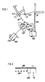
Figure 1 shows a self-moving unit in an environment.
Figure 2 shows the distribution of the system error.
In Figur 1 sind zur Begriffsklärung Grundlagen des erfindungsgemäßen Verfahrens dargestellt. Es ist eine mobile Einheit E auf verschiedenen Positionen dargestellt, die für das erfindungsgemäße Verfahren charakteristisch sind. Weiterhin ist eine Landmarke L zu erkennen, deren Lage bestimmt wird.In Figure 1, the basics of the invention for clarifying the term Procedure illustrated. It is a mobile unit E shown in different positions for the Methods according to the invention are characteristic. Still is to recognize a landmark L, the location of which is determined.
Zur Beginn ihrer Bewegung befindet sich hier beispielsweise die mobile Einheit E einer Position P1K, die mit einer Unsicherheit U1K behaftet ist. Diese Positionsunsicherheit ist durch eine Ellipse dargestellt. Nach einem Bewegungsvorgang befindet sich die Einheit an einer Position P2P. Diese Position P2P ist eine prädizierte Position, d.h. aufgrund der Messungen mit beispielsweise einem Odometer sollte sich in Relation zur Ausgangsposition P1K die mobile Einheit nun an der Position P2P befinden. Diese Position entspricht jedoch nicht dem realen Aufenthaltsort der Einheit in der Umgebung, da die Wegmessung fehlerbehaftet ist. Die Position P2P ist beispielsweise in einer Umgebungskarte in einem Orientierungsrechner der mobilen Einheit als aktuelle Position gespeichert und als aktuelle Position in der Umgebungskarte eingetragen. Aufgrund einer von der Position P1K durchgeführten Entfernungsmessung zur Landmarke in LR, wird nun von der Position P2P ein Abstand MP zur vermeintlichen Lage LP der Landmarke prädiziert. Die Lage LP der Landmarke L weist in diesem Fall eine mit einer Ellipse dargestellte Unsicherheit ULP auf.At the beginning of their movement, for example, is here the mobile unit E of a position P1K, which with a Uncertainty U1K is afflicted. This positional uncertainty is represented by an ellipse. After a movement the unit is at a P2P position. This position P2P is a predicted position, i.e. based on the measurements with, for example, an odometer should be in relation to the Starting position P1K the mobile unit is now at position P2P are located. However, this position does not correspond to the real one Location of the unit in the area as the distance measurement is faulty. The position P2P is in one, for example Map of the surroundings in a mobile orientation computer Unit saved as current position and as current position entered in the area map. Because of one of the position P1K distance measurement to the landmark in LR, a distance MP is now from the position P2P predicted location LP of the landmark. The location LP the landmark L in this case has one with an ellipse represented uncertainty ULP.
Die Position P2P ist jedoch nicht die reale Position, welche von der Einheit eingenommen wird. In Wirklichkeit befindet sie sich an der Position P2R. Durch eine Messung mit einem Entfernungsmessgerät, beispielsweise einem Laserradar oder einem Ultraschallsensor wird nun der reale Abstand der Einheit MR zur Lage der Landmarke LR bestimmt. Hierbei ist zu beachten, daß weder die Position P2R, noch die Lage LR der Landmarke eine Unsicherheit aufweisen, da es sich hierbei um die realen Positionen handelt. Falls Entfernungsmeßgeräte, die einen Fehler aufweisen, verwendet werden, wäre er hier zu berücksichtigen. Seine Verarbeitung ist jedoch nicht notwendig zur Durchführung des erfindungsgemäßen Verfahrens.However, the P2P position is not the real position, which is taken up by the unit. In reality it is located they are at position P2R. By measuring with a Distance measuring device, for example a laser radar or The real distance of the unit is now an ultrasonic sensor MR determined the location of the landmark LR. It should be noted here that neither the position P2R nor the position LR of the landmark one Uncertainty as this is the real one Positions. If distance measuring devices, the one If errors are used, it would have to be taken into account here. However, its processing is not necessary for Implementation of the method according to the invention.
Wie das in der zitierten Literatur genauer beschrieben ist, wird beispielsweise die Position einer mobilen Einheit in Form von Koordinaten und in Form einer Orientierung, die im Koordinatensystem einen Drehwinkel der Einheit angibt, beschrieben. Daraus kann man ersehen, daß eine Abstandsmessung auch abhängig von der Drehorientierung der mobilen Einheit in einem Koordinatensystem ist. Beispielsweise sind diese Drehorientierungen und der Abstand bei der Korrektur der Position und der Landmarke der mobilen Einheit zu berücksichtigen.As described in more detail in the literature cited is, for example, the position of a mobile unit in Form of coordinates and in the form of an orientation in the coordinate system indicates an angle of rotation of the unit. From this you can see that a distance measurement is also dependent from the rotating orientation of the mobile unit in one Coordinate system is. For example, these are rotational orientations and the distance when correcting the position and the Landmark of the mobile unit to be considered.
Da nun die Größen, die für das erfindungsgemäße Verfahren Voraussetzung sind, zur Verfügung stehen, kann es durchgeführt werden.Now that the sizes for the inventive method Prerequisite are available, it can be done will.
Das heißt, nun wird der reale Abstand MR mit dem prädizierten Abstand verglichen und es wird beispielsweise die Differenz v gebildet. Diese Differenz weist in Abhängigkeit der Lageunsicherheit ULP und der Positionsunsicherheit U2P eine Unsicherheit auf. Sie kann beispielsweise entsprechend aufgeteilt werden und mit dem jeweiligen Anteil die Lage der Landmarke und die Position der mobilen Einheit in der Umgebungskarte korrigiert werden. Man erhält für die Landmarke dann beispielsweise die Position LK mit einer Unsicherheit ULK, wobei zu beachten ist, daß die Unsicherheit ULK kleiner ist als die Unsicherheit ULP. Für die mobile Einheit erhält man nach der Durchführung des erfindungsgemäßen Verfahrens die Position P2K mit einer Unsicherheit U2K, wobei wiederum gilt, daß diese Unsicherheit U2K geringer ist als die Unsicherheit U2P.That is, the real distance MR is now compared with the predicted one The distance is compared and, for example, the difference v formed. This difference depends on the Positional uncertainty ULP and positional uncertainty U2P one Uncertainty. For example, it can be divided accordingly the location of the landmark and the respective share and the position of the mobile unit in the area map Getting corrected. You then get for the landmark for example the position LK with an uncertainty ULK, where it should be noted that the uncertainty ULK is less than the uncertainty ULP. For the mobile unit you get the implementation of the method according to the invention P2K with an uncertainty U2K, which in turn applies that this Uncertainty U2K is less than uncertainty U2P.
Bei einer Verwendung dieser neuen Werte für einen weiteren Schritt des erfindungsgemäßen Verfahrens in der Startkarte, kann man auf einer geringeren Unsicherheit aufsetzen und somit neue Positionen der Einheit und neue Lagen von Landmarken mit einer größeren Genauigkeit bestimmen.When using these new values for another Step of the method according to the invention in the start card, can be based on less uncertainty and thus new positions of the unit and new locations of landmarks determine with greater accuracy.
Figur 2 veranschaulicht die Berechnung des Systemfehlers nach dem erfindungsgemäßen Verfahren. Es sind dargestellt, die reale Messung MR und die prädizierte Abstandsmessung MP. Die Differenz aus diesen beiden Abständen ergibt beispielsweise den Systemfehler v. Dieser Systemfehler wird nun beispielsweise in eine Lagekorrektur LKO und eine Positionskorrektur PK aufgeteilt. Die Aufteilung erfolgt beispielsweise nach der Größe der jeweiligen Unsicherheit, mit der die Positionsbestimmung, bzw. die Lagebestimmung behaftet ist. Mit der Lagekorrektur LKO kann die Lage einer Landmarke korrigiert und mit der Positionskorrektur PK die Position der mobilen Einheit in der Umgebungskarte neu festgelegt werden. Hierbei ist zu beachten, daß bei der Korrektur sowohl die Position der mobilen Einheit in einem Koordinatensystem zu einer bestimmten Zeit, als auch die Drehrichtung der mobilen Einheit zu berücksichtigen ist.Figure 2 illustrates the calculation of the system error by the method according to the invention. It is shown that real measurement MR and the predicted distance measurement MP. The The difference between these two distances is, for example, the System error v. This system error is now, for example, in split a position correction LKO and a position correction PK. The breakdown is based on size, for example the respective uncertainty with which the position determination, or the situation is afflicted. With the LKO position correction can correct the position of a landmark and with the position correction PK the position of the mobile unit in the Area map to be redefined. It should be noted here that when correcting both the position of the mobile unit in a coordinate system at a given time, as well the direction of rotation of the mobile unit must be taken into account.
Die Korrektur der jeweiligen Positionen bzw. Lage kann dann durch Anwendung der entsprechenden Winkelfunktionen auf die Koordinatenwerte erfolgen. Bei der Zuordnung eines Meßwertes von einer Landmarke zu einer in der Umgebungskarte vorhanden Landmarke ist dieser Fehler als Schranke für die Zulässigkeit einer Zuordnung nützlich. Er sollte dabei beispielsweise zunächst einen festgelegten Wert nicht überschreiten. The correction of the respective positions or location can then by using the appropriate angular functions the coordinate values are done. When assigning a measured value from a landmark to one on the map This error is a landmark as a barrier to admissibility an assignment useful. He should, for example initially do not exceed a specified value.
Das erfindungsgemäße Verfahren geht von einer dynamisch
variierten Validation-Gate Größe aus. Zuerst wird versucht,
anhand eines strengen Kriteriums die Messungen den Landmarken
zuzuordnen und damit deren Position in der Umgebungskarte und
in Relation dazu die Position der mobilen Einheit zu bestimmen.
Werden genügend Zuordnungen gefunden, z.B. ein gewisser
Prozentsatz der prädizierten Zuordnungen werden tatsächlich
akzeptiert, dann werden nur die Zuordnungen gewählt, die dieses
strenge Kriterium erfüllen. Ist dies aus einem der eingangs
geschilderten Gründe nicht möglich, wird das Validation-Gate
etwas vergrößert, um auch etwas unsichere Zuordnungen zu
erlauben. Dieser Vorgang wird solange fortgeführt, bis beispielsweise
die erlaubten Zuordnungen einen gewissen Prozentsatz
der prädizierten Zuordnungen überschreiben, oder aber eine
maximale Anzahl an Schritten durchgeführt ist. Letzteres ist
auch nötig, da es in bestimmten Situationen, wenn z.B. ein
Gebiet völlig verändert wurde, nie möglich ist, das Prozentsatzkriterium
zu erfüllen. Beispielsweise wird für den Zusammennhang
zwischen der anfänglichen Größe γmin, der maximalen
Größe γmax und der maximalen Anzahl der Iterationen folgende
Formel gewählt:

Beispielsweise ergeben in ganz normalen Büroumgebungen Wert von γmin = 2, γmax = 4, nmax = 3 und T = 0,67 eine Steigerung von bis zu 200% in der Genauigkeit der Positionsbestimmung von Landmarken gegenüber herkömmlichen Verfahren.
For example, in normal office environments values of γ min = 2, γ max = 4, n max = 3 and T = 0.67 result in an increase of up to 200% in the accuracy of the position determination of landmarks compared to conventional methods.
Claims (12)
- Method of determining the position of a landmark in the environment map of a self-propelled unit, the distance of the landmark from the unit being determined dynamically by the latter,a) in which, at least by the unit (E), a position change is determined by at least one first measuring means arranged on the unit,b) in which, by the unit, at least one distance (MR) of a first obstacle in the environment relative to the unit (E) is determined by at least one second measuring means arranged on the unit, and is entered in the environment map as first landmark (L),c) in which, at least at a starting position, the position (P1K) of the unit (E) and the location (LR) of the first landmark (L) in the environment map correspond to the real relationships in the environment,d) in which, after a movement away of the unit, at least one first own position (P2P) of the unit (E) relative to the starting position (P1K) is determined with a position uncertainty (U2P),e) in which, from the first own position (P2P), at least one first distance (MP) to the first obstacle is determined with a position uncertainty (ULP) and a first distance to a suspected second obstacle, a determining landmark, is measured,f) in which, from a second own position, at least one second distance to the suspected second obstacle is measured,g) in which, for the second own position, using the first distance (MP) and the position change between the first own position and the second own position, a predicted second distance to the first and to the second obstacle is calculated,h) in which, as the first and second system error (v), at least the difference between the measured second distance to the suspected second obstacle and the calculated predicted second distance to the first and to the suspected second obstacle is determined,i) and in which, for determining the position of the first landmark, the latter is allocated the position of the suspected second obstacle in the environment map if the magnitude of the second system error falls below a fixed unit and is positive.
- Method according to Claim 1, in which, from at least two chronologically successive system errors, a probability is calculated for the size of the system error, and in which only such landmarks as are located in front of the unit in the direction of travel are determined.
- Method according to one of Claims 1 and 2, in which, in the event that the position of a landmark can no longer be determined, since the system error is becoming too large, the limit is raised.
- Method according to one of Claims 1 to 3, in which the raising of the limit can be carried out only to the extent to which the ratio of the number of determined landmarks to the number of predicted landmarks does not exceed a fixed value, the reliability limit.
- Method according to one of the preceding claims, which is carried out repeatedly and in which, for the case in which no location of a landmark can be determined, the number of repetitions is restricted.
- Method according to one of the preceding claims, in which an oedometer is used as first measuring means.
- Method according to one of the preceding claims, in which a distance meter is used as second measuring means.
- Method according to one of the preceding claims, in which the measurement inaccuracy of at least one measuring means is added to the system error.
- Method according to one of the preceding claims, in which the measurement inaccuracy of at least one measuring means is partitioned and one part is added to the position uncertainty and another part to the location uncertainty.
- Method according to one of the preceding claims,a) in which the system error at time k is determined to befrom which the statistical distance between the measurement and the predicted measurement is derived as

with γ max = γ min + n max as prescribed range, where n is the maximum number of possible iterations,
with a measurement error R(k+1) and with- v(k+1) :
- System error at time k+1
- z and(k+1|k) :
- Calculated predicted landmark distance at time k+1 with z and(k +1|k)= h(x and(k +1|k),p andt (k +1|k))
- x and(k+1|k) :
- Predicted own position of the unit at time k+1
- p andt (k+1|k) :
- Predicted landmark position of the unit at time k+1
- ▿:

- Jacobean Jacobean of the function h, modulus p andt (k+1|k)
- ▿:

- Jacobean of the function h, modulus x and(k+1|k)
- P(k+1|k) :
- Covariance matrix of x and(k+1|k) at time k+1
- Λt(k+1|k) :
- Covariance matrix of p andt (k+1|k) at time k+1
- Indices ^ :
- Predicted value
- Method according to Claim 10, in which R(k+1) = 0 applies.
- Method according to one of Claims 10 and 11, in which the following limits apply:
γmax = 4, γmin = 2 n max = 3 and, as reliability limit, 1.5.
Applications Claiming Priority (3)
| Application Number | Priority Date | Filing Date | Title |
|---|---|---|---|
| DE4431752 | 1994-09-06 | ||
| DE4431752 | 1994-09-06 | ||
| PCT/DE1995/001204 WO1996007959A1 (en) | 1994-09-06 | 1995-09-05 | Process for determining the position of a landmark in the map of the environment of an automotive unit which dynamically determines its distance from the landmark |
Publications (2)
| Publication Number | Publication Date |
|---|---|
| EP0779998A1 EP0779998A1 (en) | 1997-06-25 |
| EP0779998B1 true EP0779998B1 (en) | 1998-03-25 |
Family
ID=6527570
Family Applications (1)
| Application Number | Title | Priority Date | Filing Date |
|---|---|---|---|
| EP95929756A Expired - Lifetime EP0779998B1 (en) | 1994-09-06 | 1995-09-05 | Process for determining the position of a landmark in the map of the environment of an automotive unit which dynamically determines its distance from the landmark |
Country Status (5)
| Country | Link |
|---|---|
| US (1) | US5957984A (en) |
| EP (1) | EP0779998B1 (en) |
| JP (1) | JP3770909B2 (en) |
| DE (1) | DE59501731D1 (en) |
| WO (1) | WO1996007959A1 (en) |
Families Citing this family (22)
| Publication number | Priority date | Publication date | Assignee | Title |
|---|---|---|---|---|
| DE10004409A1 (en) * | 2000-02-02 | 2001-09-06 | Siemens Ag | Method for computer-aided processing of a structure comprising a first element and a second element |
| WO2003026474A2 (en) * | 2001-09-26 | 2003-04-03 | Friendly Robotics Ltd. | Robotic vacuum cleaner |
| IL145680A0 (en) | 2001-09-26 | 2002-06-30 | Friendly Robotics Ltd | Robotic vacuum cleaner |
| US7015831B2 (en) | 2002-12-17 | 2006-03-21 | Evolution Robotics, Inc. | Systems and methods for incrementally updating a pose of a mobile device calculated by visual simultaneous localization and mapping techniques |
| US7689321B2 (en) * | 2004-02-13 | 2010-03-30 | Evolution Robotics, Inc. | Robust sensor fusion for mapping and localization in a simultaneous localization and mapping (SLAM) system |
| US8996172B2 (en) | 2006-09-01 | 2015-03-31 | Neato Robotics, Inc. | Distance sensor system and method |
| US8213706B2 (en) * | 2008-04-22 | 2012-07-03 | Honeywell International Inc. | Method and system for real-time visual odometry |
| DE102008055159A1 (en) * | 2008-12-29 | 2010-07-01 | Robert Bosch Gmbh | Adaptive angle and power adjustment for 3D micromirror lidar |
| CA2772636A1 (en) | 2009-08-31 | 2011-03-03 | Neato Robotics, Inc. | Method and apparatus for simultaneous localization and mapping of mobile robot environment |
| AU2011305154B2 (en) | 2010-09-24 | 2015-02-05 | Irobot Corporation | Systems and methods for VSLAM optimization |
| US9182235B2 (en) * | 2011-05-20 | 2015-11-10 | Hitachi, Ltd. | Locus correcting method, locus correcting apparatus, and mobile object equipment |
| US8798840B2 (en) | 2011-09-30 | 2014-08-05 | Irobot Corporation | Adaptive mapping with spatial summaries of sensor data |
| US9223312B2 (en) | 2012-06-08 | 2015-12-29 | Irobot Corporation | Carpet drift estimation using differential sensors or visual measurements |
| US9020637B2 (en) | 2012-11-02 | 2015-04-28 | Irobot Corporation | Simultaneous localization and mapping for a mobile robot |
| EP2749982B1 (en) * | 2012-11-12 | 2020-01-01 | Einhell Germany AG | Generation and updating of reference models |
| US9251587B2 (en) | 2013-04-05 | 2016-02-02 | Caterpillar Inc. | Motion estimation utilizing range detection-enhanced visual odometry |
| US9037396B2 (en) | 2013-05-23 | 2015-05-19 | Irobot Corporation | Simultaneous localization and mapping for a mobile robot |
| US10725478B2 (en) * | 2013-07-02 | 2020-07-28 | The Boeing Company | Robotic-mounted monument system for metrology systems |
| GB2538779B (en) | 2015-05-28 | 2017-08-30 | Dyson Technology Ltd | A method of controlling a mobile robot |
| US10761541B2 (en) * | 2017-04-21 | 2020-09-01 | X Development Llc | Localization with negative mapping |
| EP3454079B1 (en) * | 2017-09-12 | 2023-11-01 | Aptiv Technologies Limited | Method to determine the suitablility of a radar target as a positional landmark |
| DE102019205247A1 (en) * | 2019-04-11 | 2020-10-15 | Kuka Deutschland Gmbh | Method for controlling a mobile robot |
Family Cites Families (9)
| Publication number | Priority date | Publication date | Assignee | Title |
|---|---|---|---|---|
| US4751658A (en) * | 1986-05-16 | 1988-06-14 | Denning Mobile Robotics, Inc. | Obstacle avoidance system |
| US4809178A (en) * | 1986-05-22 | 1989-02-28 | Kabushiki Kaisha Toyota Chuo Kenkyusho | Obstacle data processing system for unmanned vehicle |
| DE3709627A1 (en) * | 1987-03-24 | 1988-10-13 | Fraunhofer Ges Forschung | SELF-DRIVING VEHICLE |
| JPH04227507A (en) * | 1990-07-02 | 1992-08-17 | Nec Corp | Method for forming and keeping map for moving robot |
| DE4138270C2 (en) * | 1991-11-21 | 1996-10-02 | Rheinmetall Ind Gmbh | Method for navigating a self-propelled land vehicle |
| JPH0680203A (en) * | 1992-03-24 | 1994-03-22 | East Japan Railway Co | Control method for floor surface cleaning robot |
| DE4324531C1 (en) * | 1993-07-21 | 1994-12-01 | Siemens Ag | Method for constructing an environmental map and for determining an individual position in the environment by a self-propelled unit |
| DE4408329C2 (en) * | 1994-03-11 | 1996-04-18 | Siemens Ag | Method for building up a cellular structured environment map of a self-moving mobile unit, which is oriented with the help of sensors based on wave reflection |
| DE4408328C2 (en) * | 1994-03-11 | 2002-09-26 | Siemens Ag | Method for setting up a cellularly structured environment map of a self-moving mobile unit, which is oriented with the aid of sensors based on wave reflection |
-
1995
- 1995-09-05 EP EP95929756A patent/EP0779998B1/en not_active Expired - Lifetime
- 1995-09-05 DE DE59501731T patent/DE59501731D1/en not_active Expired - Lifetime
- 1995-09-05 WO PCT/DE1995/001204 patent/WO1996007959A1/en active IP Right Grant
- 1995-09-05 JP JP50912296A patent/JP3770909B2/en not_active Expired - Fee Related
- 1995-09-05 US US08/809,276 patent/US5957984A/en not_active Expired - Lifetime
Also Published As
| Publication number | Publication date |
|---|---|
| EP0779998A1 (en) | 1997-06-25 |
| DE59501731D1 (en) | 1998-04-30 |
| US5957984A (en) | 1999-09-28 |
| JP3770909B2 (en) | 2006-04-26 |
| JPH10505177A (en) | 1998-05-19 |
| WO1996007959A1 (en) | 1996-03-14 |
Similar Documents
| Publication | Publication Date | Title |
|---|---|---|
| EP0779998B1 (en) | Process for determining the position of a landmark in the map of the environment of an automotive unit which dynamically determines its distance from the landmark | |
| DE4408328C2 (en) | Method for setting up a cellularly structured environment map of a self-moving mobile unit, which is oriented with the aid of sensors based on wave reflection | |
| EP3376933B1 (en) | Robot-assisted machining of a surface using a robot | |
| EP3329216A1 (en) | Determining arrangement information for a vehicle | |
| EP3662229B1 (en) | Method for determining the orientation of a robot, orientation determination apparatus of a robot, and robot | |
| EP1748301A2 (en) | Method for determining a relative position of a mobile unit by comparing with scans of a surrounding area and mobile unit | |
| WO2019072674A1 (en) | Method and device for creating an inverse sensor model and method for detecting obstacles | |
| EP3430423B1 (en) | Method for improving detection of at least one object in an environment of a motor vehicle by means of an indirect measurement using sensors, control device, driver assistance system, and motor vehicle | |
| WO2016124490A1 (en) | Processing sensor measurements of a vehicle environment with low transverse resolution | |
| EP0635773B1 (en) | Method for producing an environment card and for determining a position in the environment by an automotive unit | |
| DE102016003261A1 (en) | Method for self-localization of a vehicle in a vehicle environment | |
| DE102018209607A1 (en) | Method and device for determining a position of a motor vehicle | |
| DE102010011982A1 (en) | Method for the computer-aided creation and / or updating of a reference map for a satellite-based location of an object | |
| DE102019132150A1 (en) | Method for automatically calibrating an environment sensor, in particular a lidar sensor, of a vehicle on the basis of occupancy cards and computing device | |
| DE102017108107A1 (en) | METHOD, DEVICE AND COMPUTER READABLE STORAGE MEDIUM WITH INSTRUCTIONS FOR ESTIMATING A POSE OF A MOTOR VEHICLE | |
| EP3875908B1 (en) | Vehicle navigation and virtual track guidance device | |
| WO2006079439A2 (en) | Position determination by means of a radio locating system, in particular by means of lpr, despite time limiting failure of the radio locating components | |
| EP4148386A1 (en) | Determination of an absolute initial position of a vehicle | |
| EP4004491A1 (en) | Method for locating a vehicle | |
| DE102016223526A1 (en) | Method and device for determining a first highly accurate position of a vehicle | |
| DE102020116225B3 (en) | Method for radar-based tracking of objects external to the vehicle, object tracking device and motor vehicle | |
| DE102016222664A1 (en) | Method for installing a localization system | |
| WO2022069088A1 (en) | Map plausibility test method | |
| EP4009072A1 (en) | Method, control device and vehicle for validating the localization of a vehicle by referencing to static objects in the environment | |
| DE102021214763A1 (en) | Method and control device for controlling an automated vehicle |
Legal Events
| Date | Code | Title | Description |
|---|---|---|---|
| PUAI | Public reference made under article 153(3) epc to a published international application that has entered the european phase |
Free format text: ORIGINAL CODE: 0009012 |
|
| 17P | Request for examination filed |
Effective date: 19970206 |
|
| AK | Designated contracting states |
Kind code of ref document: A1 Designated state(s): CH DE FR GB LI |
|
| GRAG | Despatch of communication of intention to grant |
Free format text: ORIGINAL CODE: EPIDOS AGRA |
|
| GRAG | Despatch of communication of intention to grant |
Free format text: ORIGINAL CODE: EPIDOS AGRA |
|
| GRAH | Despatch of communication of intention to grant a patent |
Free format text: ORIGINAL CODE: EPIDOS IGRA |
|
| 17Q | First examination report despatched |
Effective date: 19970908 |
|
| GRAH | Despatch of communication of intention to grant a patent |
Free format text: ORIGINAL CODE: EPIDOS IGRA |
|
| GRAA | (expected) grant |
Free format text: ORIGINAL CODE: 0009210 |
|
| AK | Designated contracting states |
Kind code of ref document: B1 Designated state(s): CH DE FR GB LI |
|
| REG | Reference to a national code |
Ref country code: CH Ref legal event code: NV Representative=s name: SIEMENS SCHWEIZ AG Ref country code: CH Ref legal event code: EP |
|
| REF | Corresponds to: |
Ref document number: 59501731 Country of ref document: DE Date of ref document: 19980430 |
|
| ET | Fr: translation filed | ||
| GBT | Gb: translation of ep patent filed (gb section 77(6)(a)/1977) |
Effective date: 19980528 |
|
| PLBE | No opposition filed within time limit |
Free format text: ORIGINAL CODE: 0009261 |
|
| STAA | Information on the status of an ep patent application or granted ep patent |
Free format text: STATUS: NO OPPOSITION FILED WITHIN TIME LIMIT |
|
| 26N | No opposition filed | ||
| REG | Reference to a national code |
Ref country code: GB Ref legal event code: IF02 |
|
| REG | Reference to a national code |
Ref country code: CH Ref legal event code: PCAR Free format text: SIEMENS SCHWEIZ AG;INTELLECTUAL PROPERTY FREILAGERSTRASSE 40;8047 ZUERICH (CH) |
|
| PGFP | Annual fee paid to national office [announced via postgrant information from national office to epo] |
Ref country code: CH Payment date: 20091208 Year of fee payment: 15 |
|
| REG | Reference to a national code |
Ref country code: CH Ref legal event code: PL |
|
| PG25 | Lapsed in a contracting state [announced via postgrant information from national office to epo] |
Ref country code: LI Free format text: LAPSE BECAUSE OF NON-PAYMENT OF DUE FEES Effective date: 20100930 Ref country code: CH Free format text: LAPSE BECAUSE OF NON-PAYMENT OF DUE FEES Effective date: 20100930 |
|
| PGFP | Annual fee paid to national office [announced via postgrant information from national office to epo] |
Ref country code: GB Payment date: 20130911 Year of fee payment: 19 Ref country code: FR Payment date: 20130924 Year of fee payment: 19 |
|
| PGFP | Annual fee paid to national office [announced via postgrant information from national office to epo] |
Ref country code: DE Payment date: 20131120 Year of fee payment: 19 |
|
| REG | Reference to a national code |
Ref country code: DE Ref legal event code: R119 Ref document number: 59501731 Country of ref document: DE |
|
| GBPC | Gb: european patent ceased through non-payment of renewal fee |
Effective date: 20140905 |
|
| REG | Reference to a national code |
Ref country code: FR Ref legal event code: ST Effective date: 20150529 |
|
| PG25 | Lapsed in a contracting state [announced via postgrant information from national office to epo] |
Ref country code: DE Free format text: LAPSE BECAUSE OF NON-PAYMENT OF DUE FEES Effective date: 20150401 Ref country code: GB Free format text: LAPSE BECAUSE OF NON-PAYMENT OF DUE FEES Effective date: 20140905 |
|
| PG25 | Lapsed in a contracting state [announced via postgrant information from national office to epo] |
Ref country code: FR Free format text: LAPSE BECAUSE OF NON-PAYMENT OF DUE FEES Effective date: 20140930 |