EP0779998B1 - Procede de determination de la position d'un point de repere dans la carte de l'environnement d'une unite automobile qui determine dynamiquement la distance qui la separe du point de repere - Google Patents
Procede de determination de la position d'un point de repere dans la carte de l'environnement d'une unite automobile qui determine dynamiquement la distance qui la separe du point de repere Download PDFInfo
- Publication number
- EP0779998B1 EP0779998B1 EP95929756A EP95929756A EP0779998B1 EP 0779998 B1 EP0779998 B1 EP 0779998B1 EP 95929756 A EP95929756 A EP 95929756A EP 95929756 A EP95929756 A EP 95929756A EP 0779998 B1 EP0779998 B1 EP 0779998B1
- Authority
- EP
- European Patent Office
- Prior art keywords
- landmark
- unit
- distance
- determined
- predicted
- Prior art date
- Legal status (The legal status is an assumption and is not a legal conclusion. Google has not performed a legal analysis and makes no representation as to the accuracy of the status listed.)
- Expired - Lifetime
Links
- 238000000034 method Methods 0.000 title claims description 38
- 238000005259 measurement Methods 0.000 claims description 27
- 239000011159 matrix material Substances 0.000 claims 2
- 230000004888 barrier function Effects 0.000 description 6
- 238000012937 correction Methods 0.000 description 5
- 238000010200 validation analysis Methods 0.000 description 4
- 238000013459 approach Methods 0.000 description 2
- 230000015572 biosynthetic process Effects 0.000 description 2
- 238000004364 calculation method Methods 0.000 description 1
- 230000015556 catabolic process Effects 0.000 description 1
- 238000007796 conventional method Methods 0.000 description 1
- 230000002596 correlated effect Effects 0.000 description 1
- 230000000875 corresponding effect Effects 0.000 description 1
- 230000001419 dependent effect Effects 0.000 description 1
- 238000011161 development Methods 0.000 description 1
- 230000018109 developmental process Effects 0.000 description 1
- 230000002349 favourable effect Effects 0.000 description 1
- 230000004807 localization Effects 0.000 description 1
- 238000004519 manufacturing process Methods 0.000 description 1
- 238000012545 processing Methods 0.000 description 1
- 239000000523 sample Substances 0.000 description 1
Images
Classifications
-
- G—PHYSICS
- G05—CONTROLLING; REGULATING
- G05D—SYSTEMS FOR CONTROLLING OR REGULATING NON-ELECTRIC VARIABLES
- G05D1/00—Control of position, course or altitude of land, water, air, or space vehicles, e.g. automatic pilot
- G05D1/02—Control of position or course in two dimensions
- G05D1/021—Control of position or course in two dimensions specially adapted to land vehicles
- G05D1/0268—Control of position or course in two dimensions specially adapted to land vehicles using internal positioning means
- G05D1/0274—Control of position or course in two dimensions specially adapted to land vehicles using internal positioning means using mapping information stored in a memory device
-
- G—PHYSICS
- G05—CONTROLLING; REGULATING
- G05D—SYSTEMS FOR CONTROLLING OR REGULATING NON-ELECTRIC VARIABLES
- G05D1/00—Control of position, course or altitude of land, water, air, or space vehicles, e.g. automatic pilot
- G05D1/02—Control of position or course in two dimensions
- G05D1/021—Control of position or course in two dimensions specially adapted to land vehicles
- G05D1/0231—Control of position or course in two dimensions specially adapted to land vehicles using optical position detecting means
- G05D1/0238—Control of position or course in two dimensions specially adapted to land vehicles using optical position detecting means using obstacle or wall sensors
- G05D1/024—Control of position or course in two dimensions specially adapted to land vehicles using optical position detecting means using obstacle or wall sensors in combination with a laser
-
- G—PHYSICS
- G05—CONTROLLING; REGULATING
- G05D—SYSTEMS FOR CONTROLLING OR REGULATING NON-ELECTRIC VARIABLES
- G05D1/00—Control of position, course or altitude of land, water, air, or space vehicles, e.g. automatic pilot
- G05D1/02—Control of position or course in two dimensions
- G05D1/021—Control of position or course in two dimensions specially adapted to land vehicles
- G05D1/0255—Control of position or course in two dimensions specially adapted to land vehicles using acoustic signals, e.g. ultra-sonic singals
-
- G—PHYSICS
- G05—CONTROLLING; REGULATING
- G05D—SYSTEMS FOR CONTROLLING OR REGULATING NON-ELECTRIC VARIABLES
- G05D1/00—Control of position, course or altitude of land, water, air, or space vehicles, e.g. automatic pilot
- G05D1/02—Control of position or course in two dimensions
- G05D1/021—Control of position or course in two dimensions specially adapted to land vehicles
- G05D1/0268—Control of position or course in two dimensions specially adapted to land vehicles using internal positioning means
- G05D1/0272—Control of position or course in two dimensions specially adapted to land vehicles using internal positioning means comprising means for registering the travel distance, e.g. revolutions of wheels
Definitions
- the invention has for its object to provide a method with its help an improved allocation of measurement results to the associated landmarks in the area map an autonomous mobile unit is possible and thus the Position determination of the unit in the environment improved becomes.
- a particular advantage of the method according to the invention is that measurements that are not clearly a landmark can be assigned via the system error and a predefined positive barrier with regard to the associated landmark can be discriminated against.
- the positive barrier means here that the predicted value should be less than the current measured value. So is advantageous by the invention Procedure ensures that in dynamic changing environments, for example when between two Intervals of measurement an obstacle between a landmark and the mobile mobile unit, this landmark is not an incorrect value is assigned.
- the method according to the invention from the set of those available in the area map Landmarks only evaluated those that are within a Area in the direction of travel in front of the unit.
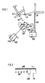
- Figure 1 shows a self-moving unit in an environment.
- Figure 2 shows the distribution of the system error.
- the mobile unit E of a position P1K which with a Uncertainty U1K is afflicted.
- This positional uncertainty is represented by an ellipse.
- the unit is at a P2P position.
- This position P2P is a predicted position, i.e. based on the measurements with, for example, an odometer should be in relation to the Starting position P1K the mobile unit is now at position P2P are located. However, this position does not correspond to the real one Location of the unit in the area as the distance measurement is faulty.
- the position P2P is in one, for example Map of the surroundings in a mobile orientation computer Unit saved as current position and as current position entered in the area map. Because of one of the position P1K distance measurement to the landmark in LR, a distance MP is now from the position P2P predicted location LP of the landmark.
- the location LP the landmark L in this case has one with an ellipse represented uncertainty ULP.
- the P2P position is not the real position, which is taken up by the unit. In reality it is located they are at position P2R.
- a Distance measuring device for example a laser radar or The real distance of the unit is now an ultrasonic sensor MR determined the location of the landmark LR. It should be noted here that neither the position P2R nor the position LR of the landmark one Uncertainty as this is the real one Positions. If distance measuring devices, the one If errors are used, it would have to be taken into account here. However, its processing is not necessary for Implementation of the method according to the invention.
- the position of a mobile unit in Form of coordinates and in the form of an orientation in the coordinate system indicates an angle of rotation of the unit. From this you can see that a distance measurement is also dependent from the rotating orientation of the mobile unit in one Coordinate system is. For example, these are rotational orientations and the distance when correcting the position and the Landmark of the mobile unit to be considered.
- the real distance MR is now compared with the predicted one
- the distance is compared and, for example, the difference v formed.
- This difference depends on the Positional uncertainty ULP and positional uncertainty U2P one Uncertainty. For example, it can be divided accordingly the location of the landmark and the respective share and the position of the mobile unit in the area map Getting corrected. You then get for the landmark for example the position LK with an uncertainty ULK, where it should be noted that the uncertainty ULK is less than the uncertainty ULP.
- P2K with an uncertainty U2K which in turn applies that this Uncertainty U2K is less than uncertainty U2P.
- FIG. 2 illustrates the calculation of the system error by the method according to the invention. It is shown that real measurement MR and the predicted distance measurement MP. The The difference between these two distances is, for example, the System error v.
- This system error is now, for example, in split a position correction LKO and a position correction PK.
- the breakdown is based on size, for example the respective uncertainty with which the position determination, or the situation is afflicted.
- With the LKO position correction can correct the position of a landmark and with the position correction PK the position of the mobile unit in the Area map to be redefined. It should be noted here that when correcting both the position of the mobile unit in a coordinate system at a given time, as well the direction of rotation of the mobile unit must be taken into account.
- the correction of the respective positions or location can then by using the appropriate angular functions the coordinate values are done.
- This error is a landmark as a barrier to admissibility an assignment useful. He should, for example initially do not exceed a specified value.
Claims (12)
- Procédé de détermination de la position d'un point de repère dans la carte de l'environnement d'une unité automobile dont la distance par rapport à l'unité est déterminée dynamiquement par cette dernière,a) dans lequel au moins l'unité (E) détermine un changement de position grâce à au moins un premier dispositif de mesure placé sur ladite unité,b) dans lequel ladite unité détermine au moins une distance (MR) d'un premier obstacle dans l'environnement par rapport à l'unité (E) grâce à au moins un deuxième dispositif de mesure placé sur ladite unité et l'inscrit comme premier point de repère (L) dans la carte de l'environnement,c) dans lequel, à au moins une position de départ, la position (P1K) de l'unité (E) et la situation (LR) du premier point de repère (L) dans la carte de l'environnement correspondent aux conditions réelles dans l'environnement,d) dans lequel, après le déplacement de l'unité, au moins une première position propre (P2P) de l'unité (E) par rapport à la position de départ (P1K) est déterminée avec une incertitude de position (U2P),e) dans lequel à partir de la première position propre (P2P), au moins une première distance (MP) du premier obstacle est déterminée avec une incertitude de situation (ULP) et une première distance d'un présumé deuxième obstacle d'un point de repère signalétique est mesuré,f) dans lequel à partir d'une deuxième position propre, au moins une deuxième distance du présumé deuxième obstacle est mesurée,g) dans lequel est calculée pour la deuxième position propre, avec la première distance (MP) et le changement de position entre la première position propre et la deuxième position propre, une deuxième distance prédite par rapport au premier et deuxième obstacle,h) dans lequel est calculée comme première et deuxième erreur système (v) au moins la différence entre la deuxième distance mesurée du présumé deuxième obstacle et la deuxième distance prédite calculée du premier et du présumé deuxième obstacle, eti) dans lequel, pour déterminer la position du premier point de repère, celui-ci se voit affecter la position du présumé deuxième obstacle dans la carte de l'environnement, si la valeur de la deuxième erreur système est inférieure à une barrière définie et si elle est positive.
- Procédé selon la revendication 1, dans lequel est calculée à partir de deux erreurs système successives dans le temps, une probabilité de l'importance de l'erreur système et dans lequel ne sont déterminés que les points de repère qui se trouvent avant l'unité dans le sens de la marche.
- Procédé selon l'une des revendications 1 à 2, dans lequel, si la position d'un point de repère ne peut plus être déterminée du fait que l'erreur système devient trop importante, la barrière est augmentée.
- Procédé selon l'une des revendications 1 à 3, dans lequel la barrière ne peut être augmentée que dans la mesure où le rapport entre le nombre des points de repère déterminés et le nombre des points de repère prédits ne dépasse pas une valeur définie, la barrière d'admissibilité.
- Procédé selon l'une quelconque des revendications précédentes, qui est répété et dans lequel le nombre de répétitions est limité, si aucune situation d'un point de repère ne peut être déterminée.
- Procédé selon l'une quelconque des revendications précédentes, dans lequel un odomètre est utilisé comme premier dispositif de mesure.
- Procédé selon l'une quelconque des revendications précédentes, dans lequel un dispositif de mesure de distance est utilisé comme deuxième dispositif de mesure.
- Procédé selon l'une quelconque des revendications précédentes, dans lequel l'imprécision de mesure d'au moins un dispositif de mesure est ajoutée à l'erreur système.
- Procédé selon l'une quelconque des revendications précédentes, dans lequel l'imprécision de mesure d'au moins un dispositif de mesure est partagée, une part étant ajoutée à l'incertitude de position et une autre part à l'incertitude de situation.
- Procédé selon l'une quelconque des revendications précédentes,a) dans lequel l'erreur système à l'instant k est déterminée par :d'où se déduit la distance statistique entre la mesure et la mesure prédite, notée :

avec une erreur de mesure R (k+1)
et avec :- v(k +1):
- erreur système à l'instant k+1
- z and(k + 1|k):
- distance prédite entre points de repère calculée à l'instant k + 1 avec z and(k +1|k)= h(x and(k +1|k),p andt (k +1|k))
- x and(k+1|k):
- position propre prédite de l'unité à l'instand k+1
- p andt (k +1|k):
- position prédite des points de repère de l'unité à l'instant k+1
- ▿:

- jacobien de la fonction h selon p andt (k + 1|k)
- ▿:

- jacobien de la fonction h selon x and(k+1|k)
- P(k + 1|k):
- matrice de covariance de x and(k+1|k) à l'instant k+1
- Λt (k + 1|k):
- matrice de covariance de p andt (k + 1|k)à l'instant k+1
- indices ^ :
- valeur prédite.
- Procédé selon la revendication 10, dans lequel R (k+1) = 0.
- Procédé selon la revendication 10 ou 11, dans lequel s'appliquent les barrières suivantes :
γmax = 4 γmin = 2n max = 3 et la barrière d'admissibilité 1,5.
Applications Claiming Priority (3)
| Application Number | Priority Date | Filing Date | Title |
|---|---|---|---|
| DE4431752 | 1994-09-06 | ||
| DE4431752 | 1994-09-06 | ||
| PCT/DE1995/001204 WO1996007959A1 (fr) | 1994-09-06 | 1995-09-05 | Procede de determination de la position d'un point de repere dans la carte de l'environnement d'une unite automobile qui determine dynamiquement la distance qui la separe du point de repere |
Publications (2)
| Publication Number | Publication Date |
|---|---|
| EP0779998A1 EP0779998A1 (fr) | 1997-06-25 |
| EP0779998B1 true EP0779998B1 (fr) | 1998-03-25 |
Family
ID=6527570
Family Applications (1)
| Application Number | Title | Priority Date | Filing Date |
|---|---|---|---|
| EP95929756A Expired - Lifetime EP0779998B1 (fr) | 1994-09-06 | 1995-09-05 | Procede de determination de la position d'un point de repere dans la carte de l'environnement d'une unite automobile qui determine dynamiquement la distance qui la separe du point de repere |
Country Status (5)
| Country | Link |
|---|---|
| US (1) | US5957984A (fr) |
| EP (1) | EP0779998B1 (fr) |
| JP (1) | JP3770909B2 (fr) |
| DE (1) | DE59501731D1 (fr) |
| WO (1) | WO1996007959A1 (fr) |
Families Citing this family (22)
| Publication number | Priority date | Publication date | Assignee | Title |
|---|---|---|---|---|
| DE10004409A1 (de) * | 2000-02-02 | 2001-09-06 | Siemens Ag | Verfahren zum rechnergestützten Bearbeiten einer Struktur umfassend ein erstes Element und ein zweites Element |
| EP1441632B1 (fr) * | 2001-09-26 | 2013-05-01 | F. Robotics Acquisitions Ltd. | Aspirateur robot |
| IL145680A0 (en) | 2001-09-26 | 2002-06-30 | Friendly Robotics Ltd | Robotic vacuum cleaner |
| US7015831B2 (en) | 2002-12-17 | 2006-03-21 | Evolution Robotics, Inc. | Systems and methods for incrementally updating a pose of a mobile device calculated by visual simultaneous localization and mapping techniques |
| US7689321B2 (en) * | 2004-02-13 | 2010-03-30 | Evolution Robotics, Inc. | Robust sensor fusion for mapping and localization in a simultaneous localization and mapping (SLAM) system |
| US8996172B2 (en) | 2006-09-01 | 2015-03-31 | Neato Robotics, Inc. | Distance sensor system and method |
| US8213706B2 (en) * | 2008-04-22 | 2012-07-03 | Honeywell International Inc. | Method and system for real-time visual odometry |
| DE102008055159A1 (de) * | 2008-12-29 | 2010-07-01 | Robert Bosch Gmbh | Adaptive Winkel- und Leistungsanpassung bei 3D-Mikrospiegel-Lidar |
| CN104699099B (zh) * | 2009-08-31 | 2018-03-23 | Neato机器人技术公司 | 移动机器人环境的同时定位和地图绘制的方法和设备 |
| CA2812723C (fr) | 2010-09-24 | 2017-02-14 | Evolution Robotics, Inc. | Systemes et procedes pour une optimisation vslam |
| JP5852645B2 (ja) * | 2011-05-20 | 2016-02-03 | 株式会社日立製作所 | 軌跡補正方法、軌跡補正装置および移動体装置 |
| US8798840B2 (en) | 2011-09-30 | 2014-08-05 | Irobot Corporation | Adaptive mapping with spatial summaries of sensor data |
| AU2013270671B2 (en) | 2012-06-08 | 2016-05-26 | Irobot Corporation | Carpet drift estimation using differential sensors or visual measurements |
| US9020637B2 (en) | 2012-11-02 | 2015-04-28 | Irobot Corporation | Simultaneous localization and mapping for a mobile robot |
| PL2749982T3 (pl) * | 2012-11-12 | 2020-06-29 | Einhell Germany Ag | Wytwarzanie i aktualizacja modelu odniesienia |
| US9251587B2 (en) | 2013-04-05 | 2016-02-02 | Caterpillar Inc. | Motion estimation utilizing range detection-enhanced visual odometry |
| US9037396B2 (en) | 2013-05-23 | 2015-05-19 | Irobot Corporation | Simultaneous localization and mapping for a mobile robot |
| US10725478B2 (en) * | 2013-07-02 | 2020-07-28 | The Boeing Company | Robotic-mounted monument system for metrology systems |
| GB2538779B (en) | 2015-05-28 | 2017-08-30 | Dyson Technology Ltd | A method of controlling a mobile robot |
| US10761541B2 (en) * | 2017-04-21 | 2020-09-01 | X Development Llc | Localization with negative mapping |
| EP3454079B1 (fr) * | 2017-09-12 | 2023-11-01 | Aptiv Technologies Limited | Procédé permettant de déterminer l'adaptabilité d'une cible radar en tant que repère de position |
| DE102019205247A1 (de) * | 2019-04-11 | 2020-10-15 | Kuka Deutschland Gmbh | Verfahren zum Steuern eines mobilen Roboters |
Family Cites Families (9)
| Publication number | Priority date | Publication date | Assignee | Title |
|---|---|---|---|---|
| US4751658A (en) * | 1986-05-16 | 1988-06-14 | Denning Mobile Robotics, Inc. | Obstacle avoidance system |
| US4809178A (en) * | 1986-05-22 | 1989-02-28 | Kabushiki Kaisha Toyota Chuo Kenkyusho | Obstacle data processing system for unmanned vehicle |
| DE3709627A1 (de) * | 1987-03-24 | 1988-10-13 | Fraunhofer Ges Forschung | Selbstfahrendes fahrzeug |
| JPH04227507A (ja) * | 1990-07-02 | 1992-08-17 | Nec Corp | 移動ロボット用のマップを作成し保持する方法 |
| DE4138270C2 (de) * | 1991-11-21 | 1996-10-02 | Rheinmetall Ind Gmbh | Verfahren zur Navigation eines selbstfahrenden Landfahrzeugs |
| JPH0680203A (ja) * | 1992-03-24 | 1994-03-22 | East Japan Railway Co | 床面洗浄ロボットの制御方法 |
| DE4324531C1 (de) * | 1993-07-21 | 1994-12-01 | Siemens Ag | Verfahren zur Erstellung einer Umgebungskarte und zur Bestimmung einer Eigenposition in der Umgebung durch eine selbstbewegliche Einheit |
| DE4408329C2 (de) * | 1994-03-11 | 1996-04-18 | Siemens Ag | Verfahren zum Aufbau einer zellular strukturierten Umgebungskarte von einer selbstbeweglichen mobilen Einheit, welche sich mit Hilfe von auf Wellenreflexion basierenden Sensoren orientiert |
| DE4408328C2 (de) * | 1994-03-11 | 2002-09-26 | Siemens Ag | Verfahren zum Aufbau einer zellular strukturierten Umgebungskarte von einer selbstbeweglichen mobilen Einheit, welche sich mit Hilfe von auf Wellenreflexion basierenden Sensoren orientiert |
-
1995
- 1995-09-05 EP EP95929756A patent/EP0779998B1/fr not_active Expired - Lifetime
- 1995-09-05 WO PCT/DE1995/001204 patent/WO1996007959A1/fr active IP Right Grant
- 1995-09-05 US US08/809,276 patent/US5957984A/en not_active Expired - Lifetime
- 1995-09-05 JP JP50912296A patent/JP3770909B2/ja not_active Expired - Fee Related
- 1995-09-05 DE DE59501731T patent/DE59501731D1/de not_active Expired - Lifetime
Also Published As
| Publication number | Publication date |
|---|---|
| WO1996007959A1 (fr) | 1996-03-14 |
| JPH10505177A (ja) | 1998-05-19 |
| EP0779998A1 (fr) | 1997-06-25 |
| DE59501731D1 (de) | 1998-04-30 |
| US5957984A (en) | 1999-09-28 |
| JP3770909B2 (ja) | 2006-04-26 |
Similar Documents
| Publication | Publication Date | Title |
|---|---|---|
| EP0779998B1 (fr) | Procede de determination de la position d'un point de repere dans la carte de l'environnement d'une unite automobile qui determine dynamiquement la distance qui la separe du point de repere | |
| DE4408328C2 (de) | Verfahren zum Aufbau einer zellular strukturierten Umgebungskarte von einer selbstbeweglichen mobilen Einheit, welche sich mit Hilfe von auf Wellenreflexion basierenden Sensoren orientiert | |
| EP3376933B1 (fr) | Usinage d'une surface assisté par robot | |
| EP3329216A1 (fr) | Détermination d'une information de disposition pour un véhicule | |
| EP3662229B1 (fr) | Procédé de détermination de la position d'un robot, dispositif de détermination de la position d'un robot et robot | |
| EP1748301A2 (fr) | Procédé destiné à la détermination d'une position relative d'une unité mobile par la comparaison de scans d'un environnement et unité mobile | |
| WO2019072674A1 (fr) | Procédé et dispositif de génération d'un modèle de capteur inverse et procédé de détection d'obstacles | |
| EP3430423B1 (fr) | Procédé d'amélioration d'une détection d'au moins un objet dans un environnement d'un véhicule automobile par une mesure indirecte avec des capteurs, dispositif de commande, système d'assistance à la conduite ainsi que véhicule automobile | |
| WO2016124490A1 (fr) | Traitement de mesures de détection de l'environnement d'un véhicule à moindre résolution transversale | |
| EP0635773B1 (fr) | Procédé d'établissement d'une carte de l'environnement et de détermination d'une position dans l'environnement au moyen d'un appareil automoteur | |
| DE102016003261A1 (de) | Verfahren zur Selbstlokalisierung eines Fahrzeugs in einer Fahrzeugumgebung | |
| DE102018209607A1 (de) | Verfahren und Vorrichtung zum Bestimmen einer Position eines Kraftfahrzeugs | |
| DE102010011982A1 (de) | Verfahren zum rechnergestützten Erstellen und/oder Aktualisieren einer Referenzkarte für eine satellitengestützte Ortung eines Objekts | |
| DE102019132150A1 (de) | Verfahren zum automatischen Kalibrieren eines Umfeldsensors, insbesondere eines Lidar-Sensors, eines Fahrzeugs auf Grundlage von Belegungskarten sowie Recheneinrichtung | |
| DE102017108107A1 (de) | Verfahren, vorrichtung und computerlesbares speichermedium mit instruktionen zur schätzung einer pose eines kraftfahrzeugs | |
| DE102019101405A1 (de) | Verfahren zum Bewerten einer Positionsinformation einer Landmarke in einer Umgebung eines Kraftfahrzeugs, Bewertungssystem, Fahrerassistenzsystem und Kraftfahrzeug | |
| EP3875908B1 (fr) | Navigation d'un véhicule et dispositif de guidage virtuel | |
| WO2006079439A2 (fr) | Determination de position au moyen d'un systeme de localisation radio, notamment par radar de positionnement local, en depit de defaillance a temps limite des composants de localisation radio | |
| EP4148386A1 (fr) | Détermination d'une position initiale absolue d'un véhicule | |
| EP4004491A1 (fr) | Procédé de localisation d'un véhicule | |
| DE102016223526A1 (de) | Verfahren und Vorrichtung zum Bestimmen einer ersten hochgenauen Position eines Fahrzeugs | |
| DE102020116225B3 (de) | Verfahren zum radarbasierten Nachverfolgen von fahrzeugexternen Objekten, Objektnachverfolgungseinrichtung und Kraftfahrzeug | |
| DE102016222664A1 (de) | Verfahren zur Installation eines Lokalisierungssystems | |
| WO2022069088A1 (fr) | Procédé d'essai de plausibilité de cartes | |
| EP4009072A1 (fr) | Procédé, appareil de commande et véhicule destinés à la validation de la localisation d'un véhicule par référencement à des objets statiques dans la zone environnante |
Legal Events
| Date | Code | Title | Description |
|---|---|---|---|
| PUAI | Public reference made under article 153(3) epc to a published international application that has entered the european phase |
Free format text: ORIGINAL CODE: 0009012 |
|
| 17P | Request for examination filed |
Effective date: 19970206 |
|
| AK | Designated contracting states |
Kind code of ref document: A1 Designated state(s): CH DE FR GB LI |
|
| GRAG | Despatch of communication of intention to grant |
Free format text: ORIGINAL CODE: EPIDOS AGRA |
|
| GRAG | Despatch of communication of intention to grant |
Free format text: ORIGINAL CODE: EPIDOS AGRA |
|
| GRAH | Despatch of communication of intention to grant a patent |
Free format text: ORIGINAL CODE: EPIDOS IGRA |
|
| 17Q | First examination report despatched |
Effective date: 19970908 |
|
| GRAH | Despatch of communication of intention to grant a patent |
Free format text: ORIGINAL CODE: EPIDOS IGRA |
|
| GRAA | (expected) grant |
Free format text: ORIGINAL CODE: 0009210 |
|
| AK | Designated contracting states |
Kind code of ref document: B1 Designated state(s): CH DE FR GB LI |
|
| REG | Reference to a national code |
Ref country code: CH Ref legal event code: NV Representative=s name: SIEMENS SCHWEIZ AG Ref country code: CH Ref legal event code: EP |
|
| REF | Corresponds to: |
Ref document number: 59501731 Country of ref document: DE Date of ref document: 19980430 |
|
| ET | Fr: translation filed | ||
| GBT | Gb: translation of ep patent filed (gb section 77(6)(a)/1977) |
Effective date: 19980528 |
|
| PLBE | No opposition filed within time limit |
Free format text: ORIGINAL CODE: 0009261 |
|
| STAA | Information on the status of an ep patent application or granted ep patent |
Free format text: STATUS: NO OPPOSITION FILED WITHIN TIME LIMIT |
|
| 26N | No opposition filed | ||
| REG | Reference to a national code |
Ref country code: GB Ref legal event code: IF02 |
|
| REG | Reference to a national code |
Ref country code: CH Ref legal event code: PCAR Free format text: SIEMENS SCHWEIZ AG;INTELLECTUAL PROPERTY FREILAGERSTRASSE 40;8047 ZUERICH (CH) |
|
| PGFP | Annual fee paid to national office [announced via postgrant information from national office to epo] |
Ref country code: CH Payment date: 20091208 Year of fee payment: 15 |
|
| REG | Reference to a national code |
Ref country code: CH Ref legal event code: PL |
|
| PG25 | Lapsed in a contracting state [announced via postgrant information from national office to epo] |
Ref country code: LI Free format text: LAPSE BECAUSE OF NON-PAYMENT OF DUE FEES Effective date: 20100930 Ref country code: CH Free format text: LAPSE BECAUSE OF NON-PAYMENT OF DUE FEES Effective date: 20100930 |
|
| PGFP | Annual fee paid to national office [announced via postgrant information from national office to epo] |
Ref country code: GB Payment date: 20130911 Year of fee payment: 19 Ref country code: FR Payment date: 20130924 Year of fee payment: 19 |
|
| PGFP | Annual fee paid to national office [announced via postgrant information from national office to epo] |
Ref country code: DE Payment date: 20131120 Year of fee payment: 19 |
|
| REG | Reference to a national code |
Ref country code: DE Ref legal event code: R119 Ref document number: 59501731 Country of ref document: DE |
|
| GBPC | Gb: european patent ceased through non-payment of renewal fee |
Effective date: 20140905 |
|
| REG | Reference to a national code |
Ref country code: FR Ref legal event code: ST Effective date: 20150529 |
|
| PG25 | Lapsed in a contracting state [announced via postgrant information from national office to epo] |
Ref country code: DE Free format text: LAPSE BECAUSE OF NON-PAYMENT OF DUE FEES Effective date: 20150401 Ref country code: GB Free format text: LAPSE BECAUSE OF NON-PAYMENT OF DUE FEES Effective date: 20140905 |
|
| PG25 | Lapsed in a contracting state [announced via postgrant information from national office to epo] |
Ref country code: FR Free format text: LAPSE BECAUSE OF NON-PAYMENT OF DUE FEES Effective date: 20140930 |