EP0779400B1 - Schraube zum Befestigen von Dämmplatten an einer Unterkonstruktion - Google Patents
Schraube zum Befestigen von Dämmplatten an einer Unterkonstruktion Download PDFInfo
- Publication number
- EP0779400B1 EP0779400B1 EP96119968A EP96119968A EP0779400B1 EP 0779400 B1 EP0779400 B1 EP 0779400B1 EP 96119968 A EP96119968 A EP 96119968A EP 96119968 A EP96119968 A EP 96119968A EP 0779400 B1 EP0779400 B1 EP 0779400B1
- Authority
- EP
- European Patent Office
- Prior art keywords
- collar
- screw
- inlet
- parts
- ramp
- Prior art date
- Legal status (The legal status is an assumption and is not a legal conclusion. Google has not performed a legal analysis and makes no representation as to the accuracy of the status listed.)
- Expired - Lifetime
Links
- 238000010276 construction Methods 0.000 title 1
- 239000002184 metal Substances 0.000 claims description 24
- 238000009413 insulation Methods 0.000 description 8
- 238000004519 manufacturing process Methods 0.000 description 2
- 238000012986 modification Methods 0.000 description 2
- 230000004048 modification Effects 0.000 description 2
- 238000005096 rolling process Methods 0.000 description 2
- 230000009286 beneficial effect Effects 0.000 description 1
- 230000015572 biosynthetic process Effects 0.000 description 1
- 238000003780 insertion Methods 0.000 description 1
- 230000037431 insertion Effects 0.000 description 1
- 239000012774 insulation material Substances 0.000 description 1
- 239000012528 membrane Substances 0.000 description 1
Images

Classifications
-
- E—FIXED CONSTRUCTIONS
- E04—BUILDING
- E04D—ROOF COVERINGS; SKY-LIGHTS; GUTTERS; ROOF-WORKING TOOLS
- E04D3/00—Roof covering by making use of flat or curved slabs or stiff sheets
- E04D3/36—Connecting; Fastening
- E04D3/3601—Connecting; Fastening of roof covering supported by the roof structure with interposition of a insulating layer
- E04D3/3603—Connecting; Fastening of roof covering supported by the roof structure with interposition of a insulating layer the fastening means being screws or nails
-
- F—MECHANICAL ENGINEERING; LIGHTING; HEATING; WEAPONS; BLASTING
- F16—ENGINEERING ELEMENTS AND UNITS; GENERAL MEASURES FOR PRODUCING AND MAINTAINING EFFECTIVE FUNCTIONING OF MACHINES OR INSTALLATIONS; THERMAL INSULATION IN GENERAL
- F16B—DEVICES FOR FASTENING OR SECURING CONSTRUCTIONAL ELEMENTS OR MACHINE PARTS TOGETHER, e.g. NAILS, BOLTS, CIRCLIPS, CLAMPS, CLIPS OR WEDGES; JOINTS OR JOINTING
- F16B5/00—Joining sheets or plates, e.g. panels, to one another or to strips or bars parallel to them
- F16B5/02—Joining sheets or plates, e.g. panels, to one another or to strips or bars parallel to them by means of fastening members using screw-thread
- F16B5/0275—Joining sheets or plates, e.g. panels, to one another or to strips or bars parallel to them by means of fastening members using screw-thread the screw-threaded element having at least two axially separated threaded portions
Definitions
- the invention is based on a screw for fastening Insulation boards on a substructure, especially a house wall or a roof structure, with a screw head, one on these subsequent thread-free shaft section and one within the Shaft section arranged, designed as a collar for Support of a sheet metal part covering an insulation board, which with a the opening allowing the screw to be pushed through is provided, whose diameter is about that of the thread-free shaft section corresponds.
- Such a screw is known from DE-PS 34 20 863.
- the stop specified namely a projecting collar, a single projection, the end of the thread of the screw and a sleeve.
- the stop for supporting the sheet metal part the is formed by a large washer, the must Opening in the sheet metal part so small that e.g. the thread or the Can sit behind the sheet metal part.
- the diameter of the bundle must exceed Go beyond the diameter of the opening so that the insertion of the Screw through the washer is only possible if doing so Washer can yield to the federal government without the Washer is deformed so that it is no longer supported by the federal government can be.
- the opening so that its diameter is smaller than the outside diameter of the thread is what screwing the washer on on the thread until the washer allows the thread-free Shaft section reached.
- the last thread turn is made delimits a plane running transversely to the screw axis, but with that Because of the thread pitch, there is only a relatively short contact area.
- the invention has for its object in a division of the federal government in at least two parts of the collar parts and the inlet ramps connected to them to be designed so that the sliding of a sheet metal part over the collar allows easily. According to the invention, this is done in that the infeed ramps of different lengths adjoining the collar parts exhibit. In the case of an advantageously designed screw, the collar is in two parts divided up.
- the sheet metal part can be a larger sheet of metal, such as they with so-called sandwich components (insulation board with mutual Metal sheets) or around a larger washer the opposite of an insulation board arranged below this necessary pressing force is exerted over a large area.
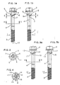
- FIG. 1a shows a screw 1 with a screw head 2, a Thread section 3 and a thread-free shaft section 4 shown, which has the shortened collar 5 in the region of this shaft section.
- the collar 5 here extends over a circumferential angle around the shaft section 4 of 180 °, as in particular from the closer below illustrated Figure 2 can be seen.
- the Bund 5 joins the Inlet ramp 6, which is parallel to the screw head 2 itself extending position of the federal government 5 runs in an inclined position, so that between the end 7 of the inlet ramp 6 and the collar 5 of the Inlet gap E results in the opening edge of a not shown here Sheet metal part can be inserted (see Figure 5).
- the Cross section of the collar 5 and the inlet ramp 6 is designed here that it is essentially a triangle with the one pointing outward Forms apex 8, the side 9 facing the screw head 2 (see Figure 1b) substantially perpendicular to the dash-dotted line Screw axis 10 runs.
- the threadless shaft section 4 is through the collar 5 with the Inlet ramp 6 divided into two parts, namely a part between Collar 5 and screw head 2 and another part between collar 5 and the threaded section 3. These two parts are the same here Diameter drawn. However, it should be noted that the Diameters can also be different, in particular it is possible the part lying between collar 5 and screw head 2 larger diameter than the other part. This can be turn out to be cheap for manufacturing and application reasons.
- FIGS. 3a and 3b a representation similar to that according to FIG Figure 1a and 1b shown a screw 12, in contrast to Screw 1 according to Figure 1a and 1b of the federal government divided into two parts is, namely in federal part 13 and in federal part 14. To the federal part 14 joins the inlet ramp 15, which belong to the collar part 13 Inlet ramp 16 (see Figure 4) is not in Figures 3a and 3b visible.
- a section along the line IV-IV of Figure 3a represents a division of the federal government into the two federal parts 13 and 14, to which the entry ramps 15 and 16 are connected. Since the two collar parts 13 and 14 are diametrically opposed, there is symmetrical support for a sheet metal part lying against it.
- a screw 18 is shown (only screw head 2 and thread-free shaft section 4), the design of which in principle corresponds to Figure 1.
- the collar 19 has its entry ramp 20 shows a cross section with an isosceles triangle corresponds radially outward apex 21.
- Such Design is particularly suitable for rolling or rolling in the Production of the collar 19 and the entry ramp 20.
- Screw here the screw 18, furthermore the sheet metal part 22 and shown a piece of an insulating plate 23 covered therefrom.
- the Sheet metal part 22 sits between the screw head 2 and the collar 19 and is therefore drawn by this according to the direction of the Arrows acting pressure on the collar 19, which is Sheet metal part 22 is supported on the collar 19.
- Such pressure can e.g. arise when a person stands on the sheet metal part 22 that together with the insulation board 23 e.g. forms the insulation of a roof.
- the Collar 19 prevents this pressure on the sheet metal part 22 Compressing the comparatively soft insulation board 23 causes what could result in the absence of a federal 19 attack, that the screw head 2 comes out far from the sheet metal part 22.
- FIGS. 6a, 6b and 7 show a variant of the design according to Figures 3a, 3b and 4, which are different Lengths of the inlet ramps adjoining two collar parts 24 and 25 26 and 27 acts, which can be clearly seen from FIG. 7.
- the Inlet ramp 26 following the collar part 24 extends only over an angle of 90 °, while the entry ramp 27 in the connection extends to the collar part 25 over an angle of 180 °.
- the latter can also be clearly seen from FIG. 6a, according to which the entry ramp 27 the relevant end of the federal government 24 overlaps.
- FIG. 6b The illustration of the screw 28 according to FIG. 6b is a rotation of the screw according to Figure 6a by 90 °, the collar 24, which extends over 90 ° (like the collar 25) from the left Side of the screw 28 migrates to the right side, the entry ramp 26 according to FIG. 7 is now visible and the entry ramp 27 partially disappears.
- the end face also appears in FIG. 6b 29 of the federal government 25, which is not visible in Figure 6a.
- the special feature of the screw 28 is that there is an entry ramp 26 extend over 90 ° and their other inlet ramp 27 over 180 °.
Landscapes
- Engineering & Computer Science (AREA)
- Mechanical Engineering (AREA)
- General Engineering & Computer Science (AREA)
- Architecture (AREA)
- Civil Engineering (AREA)
- Structural Engineering (AREA)
- Connection Of Plates (AREA)
- Roof Covering Using Slabs Or Stiff Sheets (AREA)
Description
- Fig. 1a
- eine Schraube mit verkürztem Bund in Seitensicht,
- Fig. 1b
- die gleiche Schraube um 90° gedreht,
- Fig. 2
- einen Schnitt längs der Linie II-II aus Figur 1a,
- Fig. 3a und 3b
- eine Abwandlung der Schraube gemäß Figur 1a und 1b und zwar derart, daß der Bund auf zwei Teile aufgeteilt ist,
- Fig. 4
- einen Schnitt längs der Linie IV-IV aus Figur 3a,
- Fig. 5
- eine Schraube (dargestellt ohne Gewinde) mit einem im Querschnitt einem gleichschenkligen Dreieck bildenden Bund,
- Fig. 6a und 6b
- eine Abwandlung der Schraube gemäß Figuren 3a und 3b, und zwar in dem Sinne, daß die Einlauframpen unterschiedliche Länge aufweisen,
- Fig. 7
- einen Schnitt längs der Linie VII-VII aus Figur 6a.
Claims (4)
- Schraube (28) zum Befestigen von Dämmplatten (23) an einer Unterkonstruktion, insbesondere einer Hauswand oder einer Dachkonstruktion, mit einem Schraubenkopf (2), einem an diesen anschließenden gewindefreien Schaftabschnitt (4) und einem innerhalb des Schaftabschnitts (4) angeordneten, als Bund (24/25) ausgebildeten Anschlag zur Abstützung eines eine Dämmplatte (23) abdeckenden Blechteils (22), das mit einer das Hindurchstecken der Schraube (28) ermöglichenden Öffnung versehen ist, deren Durchmesser etwa demjenigen des gewindefreien Schaftabschnitts (4) entspricht, wobei der Bund (24/25) den Schaftabschnitt (4) nur teilweise umläuft und sich an dessen einem Ende eine schräge Einlauframpe (26/27) derart anschließt, daß zwischen dem anderen Ende des Bundes (24/25) und dem Beginn der Einlauframpe (26/27) ein Einlaufspalt (E) für den Öffnungsrand des Blechteils (22) frei bleibt, in dessen Bereich die Einlauframpe (26/27) sich an die Oberfläche des Schaftabschnitts (4) annähert, und der Bund (24/25) mit seiner Einlauframpe (26/27) in mindestens zwei Teile aufgeteilt ist, wobei der Bund (24/25) in jedem seiner Teile auf gleichem Abstand zum Schraubenkopf (2) liegt, dadurch gekennzeichnet, daß die sich an die Bundteile (24,25) anschließenden Einlauframpen (26,27) unterschiedliche Längen aufweisen.
- Schraube (28) nach Anspruch 1, dadurch gekennzeichnet, daß der Bund (24/25) in zwei Bundteile aufgeteilt ist.
- Schraube nach Anspruch 2, dadurch gekennzeichnet, daß sich die eine Einlauframpe (26) über einen Winkel von 90° und die andere Einlauframpe (27) über einen Winkel von 180° erstreckt.
- Schraube nach Anspruch 2, dadurch gekennzeichnet, daß sich die beiden Bundteile (24,25) jeweils über 90° erstrecken.
Applications Claiming Priority (2)
| Application Number | Priority Date | Filing Date | Title |
|---|---|---|---|
| DE19546574 | 1995-12-13 | ||
| DE19546574A DE19546574A1 (de) | 1995-12-13 | 1995-12-13 | Schraube zum Befestigen von Dämmplatten an einer Unterkonstruktion |
Publications (2)
| Publication Number | Publication Date |
|---|---|
| EP0779400A1 EP0779400A1 (de) | 1997-06-18 |
| EP0779400B1 true EP0779400B1 (de) | 2001-11-14 |
Family
ID=7780038
Family Applications (1)
| Application Number | Title | Priority Date | Filing Date |
|---|---|---|---|
| EP96119968A Expired - Lifetime EP0779400B1 (de) | 1995-12-13 | 1996-12-12 | Schraube zum Befestigen von Dämmplatten an einer Unterkonstruktion |
Country Status (6)
| Country | Link |
|---|---|
| EP (1) | EP0779400B1 (de) |
| CZ (1) | CZ289529B6 (de) |
| DE (2) | DE19546574A1 (de) |
| HU (1) | HU219790B (de) |
| PL (1) | PL317412A1 (de) |
| TR (1) | TR199600989A2 (de) |
Cited By (1)
| Publication number | Priority date | Publication date | Assignee | Title |
|---|---|---|---|---|
| EP2278171A2 (de) | 2009-07-16 | 2011-01-26 | EJOT Baubefestigungen GmbH | Befestigungselement und -system für Anbauteile |
Families Citing this family (6)
| Publication number | Priority date | Publication date | Assignee | Title |
|---|---|---|---|---|
| DE19921542C1 (de) * | 1999-05-11 | 2001-06-28 | Duve Umformtechnik Gmbh | Befestigungsschraube |
| DE10128633C1 (de) * | 2001-06-13 | 2002-07-18 | Zahn Harald Gmbh | Trittfestes Befestigungselement |
| DE20213858U1 (de) | 2002-09-07 | 2002-11-21 | Duve Umformtechnik GmbH, 58809 Neuenrade | Schraube |
| DE102004064114B4 (de) * | 2004-12-23 | 2009-04-09 | Fischerwerke Gmbh & Co. Kg | Befestigungselement für Dämmstoffplatten |
| PL3415773T3 (pl) * | 2017-06-15 | 2020-06-29 | Sfs Intec Holding Ag | Wkręt z wielozwojowym gwintem i układ mocujący |
| DE102021117723A1 (de) | 2021-07-08 | 2023-01-12 | Ejot Se & Co. Kg | Distanzbefestiger |
Family Cites Families (6)
| Publication number | Priority date | Publication date | Assignee | Title |
|---|---|---|---|---|
| US2321378A (en) * | 1942-02-03 | 1943-06-08 | Emmet M Green | Combination screw and rivet |
| AT380051B (de) | 1983-06-22 | 1986-04-10 | Sfs Stadler Ag | Vorrichtung zum befestigen von dachbahnen auf weichem isoliermaterial an einer festen unterlage |
| DE8403242U1 (de) * | 1984-02-04 | 1984-05-03 | Schurr, Karl-Heinz, 7320 Göppingen | Senkkopf-Schraube, insbesondere zum Befestigen von hölzernen Unterkonstruktions-Teilen für Verkleidungen auf tragenden Bauteilen mit unebenen Oberflächen |
| AT380546B (de) * | 1984-06-05 | 1986-06-10 | Pointner Josef | Schraubenverbindung |
| DE9105683U1 (de) * | 1991-05-07 | 1991-08-01 | EJOT Baubefestigungen GmbH, 5928 Bad Laasphe | Befestigungselement, insbesondere zum Fixieren von Dachbahnen auf weichem Isoliermaterial an einer festen Unterlage |
| DE29608583U1 (de) * | 1996-05-14 | 1996-08-01 | Harald Zahn GmbH, 69168 Wiesloch | Trittsicheres Befestigungselement |
-
1995
- 1995-12-13 DE DE19546574A patent/DE19546574A1/de not_active Withdrawn
-
1996
- 1996-12-04 HU HU9603348A patent/HU219790B/hu not_active IP Right Cessation
- 1996-12-10 CZ CZ19963632A patent/CZ289529B6/cs not_active IP Right Cessation
- 1996-12-10 PL PL96317412A patent/PL317412A1/xx unknown
- 1996-12-11 TR TR96/00989A patent/TR199600989A2/xx unknown
- 1996-12-12 EP EP96119968A patent/EP0779400B1/de not_active Expired - Lifetime
- 1996-12-12 DE DE59608193T patent/DE59608193D1/de not_active Expired - Fee Related
Cited By (2)
| Publication number | Priority date | Publication date | Assignee | Title |
|---|---|---|---|---|
| EP2278171A2 (de) | 2009-07-16 | 2011-01-26 | EJOT Baubefestigungen GmbH | Befestigungselement und -system für Anbauteile |
| DE102010031473A1 (de) | 2009-07-16 | 2011-02-03 | Ejot Baubefestigungen Gmbh | Befestigungselement und -system für Anbauteile |
Also Published As
| Publication number | Publication date |
|---|---|
| DE59608193D1 (de) | 2001-12-20 |
| HUP9603348A1 (en) | 1997-12-29 |
| CZ363296A3 (en) | 1997-07-16 |
| CZ289529B6 (cs) | 2002-02-13 |
| TR199600989A2 (tr) | 1997-06-21 |
| DE19546574A1 (de) | 1997-06-19 |
| HU9603348D0 (en) | 1997-01-28 |
| HU219790B (hu) | 2001-08-28 |
| PL317412A1 (en) | 1997-06-23 |
| EP0779400A1 (de) | 1997-06-18 |
Similar Documents
| Publication | Publication Date | Title |
|---|---|---|
| DE102011080505B4 (de) | Befestigungselement | |
| EP0394719A1 (de) | Gewindeformende Schraube | |
| EP3097313B1 (de) | Schraube, befestigungsanordnung und verwendung einer schraube | |
| EP1961976A2 (de) | Befestigungseinheit | |
| EP1064466B1 (de) | Stanzniet | |
| DE102017100373A1 (de) | Vorrichtung zur Sicherung von Personen gegen Absturz | |
| DE102009038119B4 (de) | Befestigen von Plattenelementen | |
| EP0273863A1 (de) | Bolzen und Gegenstück | |
| EP3569880A1 (de) | Schwimmende, verliergesicherte anordnung eines verbindungselementes an einem bauteil | |
| EP0628734B1 (de) | Befestigungselement zum lösbaren Verbinden eines Mehrkantrohres, vorzugsweise eines Vierkantrohres | |
| AT407539B (de) | Einrichtung zur distanzierten befestigung von wärmedämmplatten an wänden oder decken | |
| EP0319812A1 (de) | Selbstbohrende Schraube | |
| EP1813827B1 (de) | Schraube und Verfahren zum Herstellen einer Schraube | |
| DE19546574A1 (de) | Schraube zum Befestigen von Dämmplatten an einer Unterkonstruktion | |
| DE2639446C2 (de) | ||
| DE102009049091A1 (de) | Befestigungselement | |
| EP2119918B1 (de) | Befestigung eines Pumpenlaufrades | |
| DE29503767U1 (de) | Befestigungselement | |
| EP1577571B1 (de) | Befestigungselement, Unterlegscheibe sowie Befestigungsmittel hieraus | |
| DE102005041586A1 (de) | Gewindefurchende Schraube | |
| WO2017102376A1 (de) | Gewindeelement | |
| DE3403128A1 (de) | Schraubverbindung | |
| DE19708286B4 (de) | Blechteil | |
| DE102020207059A1 (de) | Gefälledämmungsschraube zur einstellbaren Befestigung einer Dachbahn auf einem Stahlblech | |
| EP4256210B1 (de) | Unterlegscheibe zur abdeckung von langlöchern |
Legal Events
| Date | Code | Title | Description |
|---|---|---|---|
| PUAI | Public reference made under article 153(3) epc to a published international application that has entered the european phase |
Free format text: ORIGINAL CODE: 0009012 |
|
| AK | Designated contracting states |
Kind code of ref document: A1 Designated state(s): CH DE FR GB IT LI NL SE |
|
| 17P | Request for examination filed |
Effective date: 19971119 |
|
| 17Q | First examination report despatched |
Effective date: 20010126 |
|
| GRAG | Despatch of communication of intention to grant |
Free format text: ORIGINAL CODE: EPIDOS AGRA |
|
| GRAG | Despatch of communication of intention to grant |
Free format text: ORIGINAL CODE: EPIDOS AGRA |
|
| GRAH | Despatch of communication of intention to grant a patent |
Free format text: ORIGINAL CODE: EPIDOS IGRA |
|
| GRAH | Despatch of communication of intention to grant a patent |
Free format text: ORIGINAL CODE: EPIDOS IGRA |
|
| GRAA | (expected) grant |
Free format text: ORIGINAL CODE: 0009210 |
|
| AK | Designated contracting states |
Kind code of ref document: B1 Designated state(s): CH DE FR GB IT LI NL SE |
|
| PG25 | Lapsed in a contracting state [announced via postgrant information from national office to epo] |
Ref country code: NL Free format text: LAPSE BECAUSE OF FAILURE TO SUBMIT A TRANSLATION OF THE DESCRIPTION OR TO PAY THE FEE WITHIN THE PRESCRIBED TIME-LIMIT Effective date: 20011114 Ref country code: IT Free format text: LAPSE BECAUSE OF FAILURE TO SUBMIT A TRANSLATION OF THE DESCRIPTION OR TO PAY THE FEE WITHIN THE PRE;WARNING: LAPSES OF ITALIAN PATENTS WITH EFFECTIVE DATE BEFORE 2007 MAY HAVE OCCURRED AT ANY TIME BEFORE 2007. THE CORRECT EFFECTIVE DATE MAY BE DIFFERENT FROM THE ONE RECORDED.SCRIBED TIME-LIMIT Effective date: 20011114 |
|
| REG | Reference to a national code |
Ref country code: CH Ref legal event code: EP |
|
| GBT | Gb: translation of ep patent filed (gb section 77(6)(a)/1977) |
Effective date: 20011114 |
|
| REF | Corresponds to: |
Ref document number: 59608193 Country of ref document: DE Date of ref document: 20011220 |
|
| PG25 | Lapsed in a contracting state [announced via postgrant information from national office to epo] |
Ref country code: LI Free format text: LAPSE BECAUSE OF NON-PAYMENT OF DUE FEES Effective date: 20011231 Ref country code: CH Free format text: LAPSE BECAUSE OF NON-PAYMENT OF DUE FEES Effective date: 20011231 |
|
| REG | Reference to a national code |
Ref country code: GB Ref legal event code: IF02 |
|
| PG25 | Lapsed in a contracting state [announced via postgrant information from national office to epo] |
Ref country code: SE Free format text: LAPSE BECAUSE OF FAILURE TO SUBMIT A TRANSLATION OF THE DESCRIPTION OR TO PAY THE FEE WITHIN THE PRESCRIBED TIME-LIMIT Effective date: 20020214 |
|
| ET | Fr: translation filed | ||
| NLV1 | Nl: lapsed or annulled due to failure to fulfill the requirements of art. 29p and 29m of the patents act | ||
| REG | Reference to a national code |
Ref country code: CH Ref legal event code: PL |
|
| PLBE | No opposition filed within time limit |
Free format text: ORIGINAL CODE: 0009261 |
|
| STAA | Information on the status of an ep patent application or granted ep patent |
Free format text: STATUS: NO OPPOSITION FILED WITHIN TIME LIMIT |
|
| 26N | No opposition filed | ||
| REG | Reference to a national code |
Ref country code: FR Ref legal event code: ST |
|
| REG | Reference to a national code |
Ref country code: FR Ref legal event code: RN |
|
| REG | Reference to a national code |
Ref country code: FR Ref legal event code: FC |
|
| PGFP | Annual fee paid to national office [announced via postgrant information from national office to epo] |
Ref country code: GB Payment date: 20071212 Year of fee payment: 12 Ref country code: FR Payment date: 20071210 Year of fee payment: 12 |
|
| PGFP | Annual fee paid to national office [announced via postgrant information from national office to epo] |
Ref country code: DE Payment date: 20081219 Year of fee payment: 13 |
|
| GBPC | Gb: european patent ceased through non-payment of renewal fee |
Effective date: 20081212 |
|
| REG | Reference to a national code |
Ref country code: FR Ref legal event code: ST Effective date: 20090831 |
|
| PG25 | Lapsed in a contracting state [announced via postgrant information from national office to epo] |
Ref country code: GB Free format text: LAPSE BECAUSE OF NON-PAYMENT OF DUE FEES Effective date: 20081212 |
|
| PG25 | Lapsed in a contracting state [announced via postgrant information from national office to epo] |
Ref country code: DE Free format text: LAPSE BECAUSE OF NON-PAYMENT OF DUE FEES Effective date: 20100701 |
|
| PG25 | Lapsed in a contracting state [announced via postgrant information from national office to epo] |
Ref country code: FR Free format text: LAPSE BECAUSE OF NON-PAYMENT OF DUE FEES Effective date: 20081231 |