EP0779249B1 - Actuating assembly for moving glass articles - Google Patents
Actuating assembly for moving glass articles Download PDFInfo
- Publication number
- EP0779249B1 EP0779249B1 EP96119889A EP96119889A EP0779249B1 EP 0779249 B1 EP0779249 B1 EP 0779249B1 EP 96119889 A EP96119889 A EP 96119889A EP 96119889 A EP96119889 A EP 96119889A EP 0779249 B1 EP0779249 B1 EP 0779249B1
- Authority
- EP
- European Patent Office
- Prior art keywords
- assembly
- passages
- pneumatic actuator
- conduits
- pairs
- Prior art date
- Legal status (The legal status is an assumption and is not a legal conclusion. Google has not performed a legal analysis and makes no representation as to the accuracy of the status listed.)
- Expired - Lifetime
Links
- 239000011521 glass Substances 0.000 title claims description 7
- 230000001419 dependent effect Effects 0.000 claims 1
- 230000013011 mating Effects 0.000 claims 1
- 230000000712 assembly Effects 0.000 description 15
- 238000000429 assembly Methods 0.000 description 15
- 239000003638 chemical reducing agent Substances 0.000 description 3
- 238000001816 cooling Methods 0.000 description 3
- 230000006870 function Effects 0.000 description 3
- 230000004323 axial length Effects 0.000 description 2
- 230000005540 biological transmission Effects 0.000 description 2
- 238000004519 manufacturing process Methods 0.000 description 2
- 230000003213 activating effect Effects 0.000 description 1
- 230000015572 biosynthetic process Effects 0.000 description 1
- 238000006243 chemical reaction Methods 0.000 description 1
- 239000012809 cooling fluid Substances 0.000 description 1
- 230000006386 memory function Effects 0.000 description 1
- 230000008520 organization Effects 0.000 description 1
- 230000000284 resting effect Effects 0.000 description 1
- 239000007787 solid Substances 0.000 description 1
- 230000001360 synchronised effect Effects 0.000 description 1
Images




Classifications
-
- C—CHEMISTRY; METALLURGY
- C03—GLASS; MINERAL OR SLAG WOOL
- C03B—MANUFACTURE, SHAPING, OR SUPPLEMENTARY PROCESSES
- C03B9/00—Blowing glass; Production of hollow glass articles
- C03B9/30—Details of blowing glass; Use of materials for the moulds
- C03B9/44—Means for discharging combined with glass-blowing machines, e.g. take-outs
- C03B9/453—Means for pushing newly formed glass articles onto a conveyor, e.g. sweep-out mechanisms; Dead-plate mechanisms
Definitions
- the present invention relates to an actuating assembly for moving glass articles, in particular, hollow glass articles, to which the following description refers purely by way of example.
- the articles are formed inside respective aligned, adjacent molds, and are removed from the molds and deposited on to respective supporting surfaces on which they remain for a given length of time before being transferred on to a linear conveyor by which they are fed successively to the output of the system.
- Each article is transferred from the supporting surface to the linear conveyor by means of a respective actuating assembly, which comprises a gripping member for positively engaging at least one article for transfer; a pneumatic linear actuator for moving the gripping member to and from the article for transfer; and an angular actuator for rotating the linear actuator, and hence the gripping member, about a rotation axis and between two angular limit positions.
- a respective actuating assembly which comprises a gripping member for positively engaging at least one article for transfer; a pneumatic linear actuator for moving the gripping member to and from the article for transfer; and an angular actuator for rotating the linear actuator, and hence the gripping member, about a rotation axis and between two angular limit positions.
- the linear actuator is connected to a compressed air source by means of a pneumatic circuit comprising a distribution device for supplying compressed air to the linear actuator regardless of the angular position of the linear actuator about the rotation axis.
- the compressed air distribution device comprises a distribution plate on which are formed two cavities communicating with the compressed air source and closed by a movable rotary plate facing the distribution plate to define respective separate intermediate air chambers.
- the movable plate is fitted integrally with the linear actuator, the variable-volume chambers of which are each connected to a respective intermediate chamber by a respective conduit formed through the movable plate.
- Known actuating assemblies also comprise a pair of fixed mechanical limit stops, which, in use, arrest rotation of the movable plate, and hence of the gripping member, in two angular limit positions: a pickup position in which the article is removed off the supporting surface; and a release position in which the article is deposited on to the linear conveyor.
- each assembly is constructed as a function of the characteristics of the system to which it is eventually fitted, and more specifically as a function of the precise location of the assembly in relation to the respective supporting surface, the length of the path along which the articles are to be fed, and the rotation direction (clockwise or anticlockwise) of the gripping member to feed the article along the path.
- the rotation direction of the gripping member and the length of the path in fact, determine the size and location of the intermediate chambers partly defined by the distribution plate, as well as the location of the mechanical limit stops.
- actuating assemblies of the above type also fail to provide for fast, troublefree, and hence low-cost, routine production change setup to adapt the assembly to articles of different shapes and sizes.
- an actuating assembly for moving glass articles comprising a gripping member for positively engaging an article for transfer; a pneumatic actuator for moving the gripping member, in use, to and from the article; and an angular actuator for rotating the pneumatic actuator about a rotation axis; circuit means being provided for connecting said pneumatic actuator to a source of compressed air regardless of the position of the pneumatic actuator about said rotation axis; characterized in that said circuit means comprise two pairs of passages for the compressed air; first selecting means for selectively connecting said two pairs of passages to said source of compressed air; and second selecting means for selectively connecting said two pairs of passages to the pneumatic actuator.
- Number 1 in Figure 1 indicates an actuating assembly for transferring hollow glass articles 2, in this case bottles, from a supporting surface (not shown), located adjacent to a finishing mold, on to a linear conveyor (not shown) for conveying articles 2.
- Assembly 1 comprises a frame 3 fittable integrally to a fixed body (not shown) and supporting an actuating device 3a for activating a known gripping member 5 (not described in detail) for positively engaging article 2 for transfer.
- Device 3a comprises a known electric angular actuator 4, and a pneumatic linear actuator 6.
- Linear actuator 6 is connected to and rotated by angular actuator 4 about a substantially vertical rotation axis 7 between a pickup and a release position wherein article 2 is respectively picked up and released, and comprises a body 8, and an output rod 9 to which gripping member 5 is connected integrally.
- frame 3 comprises a plate 12 to which are connected integrally the ends of four arms 13, the opposite ends of which are connected integrally, in use, to said fixed body (not shown).
- Plate 12 comprises an integral elongated intermediate body 14 extending on the opposite side of plate 12 to arms 13, and defined, on the side facing pneumatic actuator 6, by a flat surface 14a perpendicular to axis 7.
- Body 14 comprises three vertical through holes 15, 16, 17 having respective threaded bottom end portions and respective axes 18 parallel to one another and to axis 7; a further two threaded holes 19 (Figures 5 and 8) parallel to axis 7 and formed on the opposite side of holes 15, 16, 17 to plate 12; and a pair of opposite appendixes 20 extending parallel to plate 12 and forming a guide, parallel to axis 7, of a guide-slide assembly 21.
- Assembly 21 also comprises a C-shaped slide 22 connected positively and in axially-sliding manner to appendixes 20, and connected integrally to a rigid structure 23 of angular actuator 4 by means of a number of screws ( Figure 1).
- Angular actuator 4 comprises an electric step motor 24 connected to structure 23 and coaxial with axis 7; and a known speed reducer 25 (shown partially in Figure 1) connected to the shaft of motor 24, and having a respective output shaft 25a extending upwards and coaxial with axis 7.
- Motor 24 and reducer 25 are housed inside a cup-shaped casing 26 comprising an open top end portion, which is connected to an intermediate portion of structure 23 by means of a number of known elastic toggle devices 27 defining an assembly for fast-fit connecting casing 26 to rigid structure 23.
- Shaft 25a of reducer 25 is fitted with a bottom end portion 28 of a transmission member 29 connected to rigid structure 23 in axially-fixed manner and so as to rotate about axis 7 by means of a pair of bearings 30.
- Bottom portion 28 is fitted integrally with one end of an arm 31 projecting perpendicularly to axis 7, and which is rotated by motor 24 between two angular limit positions: a lateral limit position (shown by the dotted line in Figures 5 and 8) corresponding to the release position of member 5, and wherein arm 31 rests against a mechanical limit stop defined by a threaded pin 32 having a seat for an Allen wrench and screwed inside one of four threaded holes 33 formed in structure 23; and a central limit position (shown by the continuous line in Figures 2, 5 and 8) corresponding to the pickup position of member 5, and wherein arm 31 rests against a further mechanical limit stop defined by a further threaded pin 34, similar to pin 32, screwed inside one of two threaded holes 35 formed in structure 23,
- Sensor 36 comprises an externally-threaded end portion 37, and extends loosely inside a vertical through hole formed in structure 23, and into casing 26.
- Sensor 36 is connected adjustably to structure 23 by means of a retaining member 38 connected integrally to structure 23 by means of screws, and which comprises an elastic portion 39 having a threaded hole engaged by said threaded portion 37, and a screw 40 extending crosswise to the threaded hole and for elastically deforming portion 39 to clamp sensor 36 inside the threaded hole.
- transmission member 29 extends upwards through an opening 41 formed in a distribution plate 42 connected to structure 23 by means of a number of screws 42a (only one shown in Figure 1), and comprises a top end portion connected integrally to a movable plate 43 supporting linear actuator 6.
- Plate 42 extends crosswise to axis 7, and comprises an end portion 44 located over body 14 of frame 3 and in turn comprising three dead holes 45 (only one shown in Figure 1) coaxial with, and having respective inlets communicating with, respective holes 15, 16, 17.
- An end portion of a respective tubular sleeve 47, 48, 49 ( Figures 1, 8, 18) is housed inside each dead hole 45 and locked in position coaxial with respective axis 18 by a respective pin 46, and an opposite end portion of respective tubular sleeve 47, 48, 49 engages an end portion of respective hole 15, 16, 17 in axially-sliding, fluidtight manner.
- sleeves 47, 48, 49 and respective holes 15, 16, 17, together with guide-slide assembly 21, form a device 50 for connecting actuating device 3a to frame 3.
- device 50 has no guide-slide assembly 21, and only comprises sleeves 47, 48, 49 connected telescopically to respective holes 15, 16, 17.
- sleeve 48 also forms part of an air cooling circuit 50a, which, as shown, particularly in Figures 4 and 7, also comprises a conduit 51 formed in plate 42 and communicating, at one end, with hole 16 through an opening formed in the lateral wall of the portion of sleeve 48, and, at the other end, with the inside of structure 23 and casing 26 through a curved passage defined by a screw element 52 ( Figures 1 and 13).
- Element 52 is housed inside a cylindrical through seat 53 formed in plate 42 in such a position that a respective axis 53a ( Figures 1 and 13) extends parallel to axis 7 and intersects a circumference 54 coaxial with axis 7 ( Figures 3, 4, 6, 7).
- seat 53 comprises an open-topped cavity 55, and a threaded through hole 56 extending from the bottom wall of cavity 55; hole 56 is engaged by a threaded shank 57 of element 52; and a socket head 58 of element 52 extends inside cavity 55, and comprises a radial outer flange 59 resting on the bottom wall of cavity 55, and an end portion 60 extending upwards with ample radial clearance inside cavity 55 and having a socket for an Allen wrench.
- sleeves 47, 49 and respective holes 15, 17 also form part of an adaptable pneumatic circuit 61 for supplying and distributing compressed air to linear actuator 6, and, together with sleeve 48 and respective hole 16, a fast-fit connecting device 61a for simultaneously connecting, in one operation, both linear actuator 6 to its compressed air source, and the whole of device 3a to a cooling fluid circulating unit (not shown), simultaneously with connection of device 3a to frame 3.
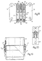
- pneumatic circuit 61 also comprises two conduits 62 ( Figure 18) connected at one end to the compressed air source in known manner, and the respective end portions of which are defined by holes 15 and 17.
- Circuit 61 also comprises a conduit 63 formed inside plate 42 and in turn comprising three straight portions 64, 65, 66, the respective axes 67 of which extend perpendicularly to axis 7, intersect one another at two points P1, P2, and intersect said circumference at three points L1, L2, L3.
- portions 64 and 66 communicate, at one end, with the inside of respective sleeves 47 and 49 through respective openings formed in the lateral walls of respective sleeves 47, 49, and, at the other end, with respective internally-threaded end portions 69 and 70 of portion 65; and threaded portions 69 and 70 comprise respective inner portions 71 extending between points of intersection P1 and P2, and respective outer portions 72 extending outwards of points P1 and P2 and communicating with the outside.
- threaded portions 69 and 70 are engaged by one or the other of two threaded pins 73 and 74, which have different axial lengths and, as described more clearly later on, are fitted to one or the other of threaded portions 69 and 70 to form assemblies 1 of different characteristics.
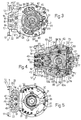
- circuit 61 also comprises a substantially annular cavity 75 formed in the surface of plate 42 facing movable plate 43 and substantially along said circumference 54; cavity 75 is defined by an annular bottom wall in which are formed three seats 76, 77, 78 of the same shape and size as seat 53, and which have respective axes 76a, 77a, 78a extending through respective points L1, L2, L3, and communicate with respective portions 64, 65, 66; seats 76 and 78 house respective screw type compressed air supply elements, which, as described more clearly later on, are selectable from two distribution elements 79 and 80 ( Figures 4 and 7) similar to element 52 and shown in Figures 11 and 12; while seat 77 permanently houses element 80.
- element 79 differs from element 52 in that threaded shank 57 is a solid shank, and comprises a through hole 81 perpendicular to the axis of shank 57 and for ensuring the continuity of portion 64, 66 through which seat 76, 78 is formed.
- element 80 differs from element 52 by comprising a dead hole 83 coaxial with the axis of element 80 and extending through head 60 and partly inside shank 57; shank 57 comprises four lateral passages 84 by which the inside of dead hole 83 communicates with respective conduit portion 64, 66; and the axial length of head 60 is greater than that of head 60 of element 52.
- annular cavity 75 houses, coaxially with axis 7, two half-rings 86 (Figure 9), each of which has the same curvature as circumference 54 and comprises a respective circumferential face groove 87 formed in the surface of the respective half-ring facing movable plate 43.
- Half-rings 86 also comprise respective through holes 88 formed along respective grooves 87 and so located that their respective axes extend through points L1 and L2 as shown in Figure 6, or through points L2 and L3 as shown in Figure 3.
- head 60 of each element 52, 79, 80 is fitted with a respective coil spring 90 extending between flange 59 of the respective distribution element and a respective half-ring 86.
- Half-ring 86 is movable between a raised assembly position ( Figure 15) and a lowered operating position ( Figure 14) in which each half-ring 86 is pushed by respective spring 90 into sliding and fluidtight contact with movable plate 43, and defines, together with movable plate 43, a respective chamber 92 ( Figure 1).
- Each chamber 92 communicates with one end (not shown) of a respective supply conduit 91 ( Figure 1) formed in movable plate 43, and the opposite end of which communicates with a respective chamber (not shown) of linear actuator 6.
- assembly 1 also comprises a screw-nut screw actuating device 93, which is operated externally to adjust the position of actuating device 3a, and hence gripping member 5, in a direction parallel to axis 7, and to disconnect device 3a from fixed supporting frame 3.
- device 93 comprises a socket-head screw 94 having a respective threaded shank 95 engaging respective hole 19; and an end portion or head 96, which engages in axially-sliding manner a cylindrical seat formed in portion 44 of fixed plate 42.
- each cylindrical seat comprises an end wall defining an axial shoulder for head 96 of respective screw 94, and communicating externally through an opening 97 formed in fixed plate 42 and for enabling screw 94 to be operated from the outside.
- fixed plate 42 also comprises a number of further openings 98, each of which, when arm 31 is set to the central position, extends coaxially with a respective threaded hole 33, 35 to enable pins 32, 34 to be moved externally from one threaded hole 33, 35 to the other.
- Assembly 1 also comprises a known electronic control unit 100, which, as shown particularly in Figure 21, comprises a known microcontroller 101 in turn comprising a memory block 102 for storing both the program and operating data, and a processing block 103.
- Microcontroller 101 comprises a number of inputs 104 for entering external drive data, e.g. an external start pulse, a manual start pulse, a stop signal, and possibly a signal for expelling article 2; and a number of outputs 105, 106, of which outputs 106 are those of processing block 103 by which to emit signals for controlling, for example, an electrovalve (if any) of pneumatic circuit 61, cooling of article 2 for transfer, and possibly an expelling device (not shown) for expelling article 2.
- Unit 100 also comprises a power module 107, preferably a bipolar chopper guide module, for controlling motor 24, and which is connected to and supplied by outputs 106 of processing block 103 with the processed control signals; a known sensor 108 for detecting the presence of gripping member 5 in the article 2 pickup position; and sensor 36 for detecting the presence of gripping member 5 in the article 2 release position.
- processing block 103 calculates in known manner the motion profile to be followed by motor 24 to move gripping member 5 between the article 2 pickup and release positions, and controls power block 107 to drive motor 24 accordingly.
- the control signals from processing block 103 are synchronized with the external signals supplied to microcontroller 101 by inputs 104.
- assembly 1 may be assembled, as required, to form left-hand actuating assemblies ( Figures 2, 6, 7 and 8) in which gripping member 5 rotates clockwise (in Figure 8) into the release position, or right-hand actuating assemblies ( Figures 3, 4 and 5) in which gripping member 5 rotates anticlockwise (in Figure 5) into the release position.
- Conduit 63 is thus divided into two separate branches A and B, which, on the one hand, communicate with the inside of respective sleeves 47 and 49, and, on the other, communicate with respective chambers 92 via respective elements 80 housed inside seats 77 and 78, and, consequently, with a respective chamber (not shown) of linear actuator 6 via respective conduit 91.
- element 79 inside seat 76 ensures the continuity of portion 64 to prevent any air leakage
- holes 83 of the two elements 80 define a pair of compressed air passages or inlet/outlet ports 83a.
- element 80 is left inside seat 77; elements 79 and 80 are inserted respectively inside seats 78 and 76; half-rings 86 are so positioned that the axes of holes 88 are aligned with points L1 and L2; and pins 73 and 74 are fitted respectively to portion 72 of portion 70 and to portion 71 of portion 69.
- Conduit 63 is thus divided into two separate branches C and D, which, on the one hand, communicate with the inside of respective sleeves 47 and 49, and, on the other, communicate with respective chamber 92, but this time via elements 80 inside seats 76 and 77.
- element 79 inside seat 78 ensures the continuity of portion 66 to prevent any air leakage
- holes 83 of elements 80 define another pair of compressed air passages or inlet/outlet ports 83b.
- Assembly 1 as described is therefore an adaptable modular assembly, i.e. enabling, at the assembly stage, the formation of a "right-hand” or “left-hand” actuating assembly using the same components but simply arranged differently, and may therefore be produced independently of its application, i.e. independently of the characteristics of the system to which it is eventually fitted.
- assembly 1 provides for quickly and easily converting a right-hand to a left-hand assembly, and vice versa, by simply rotating the two half-rings 86 substantially 90° about axis 7, switching elements 79, 80 inside seats 76, 78 and pins 73, 74 inside threaded portions 69, 70, and, depending on the length of the path of articles 2, shifting pins 32, 34 defining the mechanical limit stops inside respective holes 33, 35. Conversion is further simplified by elements 79, 80, pins 73, 74, and pins 32, 34 all being removable and replaceable using a straightforward Allen wrench.
- pins 32 and 34 being accessible directly from the outside through a number of openings 98 formed in plate 42, and by pin 34 simply being fitted inside one of the two threaded holes 35, and pin 32 inside one of the four threaded holes 33.
- assembly 1 therefore provides for drastically reducing storage, enabling immediate supply by the maker, and enabling assemblies 1 to be produced regardless of the exact configuration of the system or even exact arrangement of assembly 1 within the system itself.
- the design of assembly 1 also provides for continuous accurate adjustment of the position of gripping member 5 in relation to frame 3 and, in use, in relation to the supporting surface of article 2.
- Screw-nut screw device 93 in fact provides for both disconnecting device 3a from supporting frame 3, i.e. withdrawing device 3a gradually with practically no physical effort required, and for accurately adjusting the position of gripping member 5 working directly from the outside with an ordinary Allen wrench.
- Using a pair of screws 94 both cooperating with fixed frame 3, particularly simplifies reconnection of device 3a to frame 3 by greatly reducing the time required. That is, while one of screws 94 is used as a means for extracting device 3a, the other remains fixed and is used as a reference or locator, with a memory function, when reconnecting device 3a, which is thus automatically assembled in the previously set position.
- assembly 1 and, in particular, the provision of quick-change device 61a, and the arrangement of screw-nut screw device 93 provide for achieving highly compact assemblies.
- assembly 1 as described is relatively lightweight, thus further simplifying any handling operations.
Landscapes
- Engineering & Computer Science (AREA)
- Chemical & Material Sciences (AREA)
- Manufacturing & Machinery (AREA)
- Materials Engineering (AREA)
- Organic Chemistry (AREA)
- Manipulator (AREA)
- Re-Forming, After-Treatment, Cutting And Transporting Of Glass Products (AREA)
Applications Claiming Priority (2)
| Application Number | Priority Date | Filing Date | Title |
|---|---|---|---|
| ITTO950996 | 1995-12-12 | ||
| IT95TO000996A IT1281067B1 (it) | 1995-12-12 | 1995-12-12 | Gruppo attuatore per lo spostamento di articoli di vetro. |
Publications (2)
| Publication Number | Publication Date |
|---|---|
| EP0779249A1 EP0779249A1 (en) | 1997-06-18 |
| EP0779249B1 true EP0779249B1 (en) | 2001-08-22 |
Family
ID=11414022
Family Applications (1)
| Application Number | Title | Priority Date | Filing Date |
|---|---|---|---|
| EP96119889A Expired - Lifetime EP0779249B1 (en) | 1995-12-12 | 1996-12-11 | Actuating assembly for moving glass articles |
Country Status (4)
| Country | Link |
|---|---|
| EP (1) | EP0779249B1 (it) |
| DE (1) | DE69614652T2 (it) |
| ES (1) | ES2161322T3 (it) |
| IT (1) | IT1281067B1 (it) |
Families Citing this family (2)
| Publication number | Priority date | Publication date | Assignee | Title |
|---|---|---|---|---|
| ES2167136B1 (es) * | 1999-01-28 | 2003-10-16 | Vidrala Sa | Sacador de botellas para maquinas de moldeo de vidrio hueco. |
| US6264023B1 (en) * | 1999-03-12 | 2001-07-24 | Vidrala, S.A. | Bottle extractor for hollow glass moulding machines |
Family Cites Families (3)
| Publication number | Priority date | Publication date | Assignee | Title |
|---|---|---|---|---|
| US3559537A (en) * | 1968-06-17 | 1971-02-02 | C S S Machine & Tool Co | Push out for glassware forming machinery |
| DE2746675C2 (de) * | 1977-10-18 | 1979-10-04 | Hermann Heye, 3063 Obernkirchen | Glasformmaschine mit mehreren Stationen |
| US5160015A (en) * | 1991-09-09 | 1992-11-03 | Owens-Brockway Glass Container Inc. | Sweepout apparatus and method |
-
1995
- 1995-12-12 IT IT95TO000996A patent/IT1281067B1/it active IP Right Grant
-
1996
- 1996-12-11 ES ES96119889T patent/ES2161322T3/es not_active Expired - Lifetime
- 1996-12-11 EP EP96119889A patent/EP0779249B1/en not_active Expired - Lifetime
- 1996-12-11 DE DE69614652T patent/DE69614652T2/de not_active Expired - Lifetime
Also Published As
| Publication number | Publication date |
|---|---|
| DE69614652D1 (de) | 2001-09-27 |
| EP0779249A1 (en) | 1997-06-18 |
| DE69614652T2 (de) | 2002-07-04 |
| ITTO950996A0 (it) | 1995-12-12 |
| ES2161322T3 (es) | 2001-12-01 |
| ITTO950996A1 (it) | 1997-06-12 |
| IT1281067B1 (it) | 1998-02-11 |
Similar Documents
| Publication | Publication Date | Title |
|---|---|---|
| JP5739330B2 (ja) | プラスチック容器、特にボトルをブロー成形するためのプラント | |
| JP5557119B2 (ja) | プラスチック容器、特にボトルをブロー成形するためのプラント用成形ユニット | |
| KR102191380B1 (ko) | 인서트와 취출을 동시에 하는 사출성형기용 취출로봇장치 | |
| US6349571B1 (en) | Pushout mechanism for I.S. machine | |
| EP1112835B1 (en) | Rotary machine for making blow molded plastic vessels or bottles from a molded preform and mold therefor | |
| EP0779249A1 (en) | Actuating assembly for moving glass articles | |
| EP0779250B1 (en) | Actuating assembly for moving glass articles | |
| JP5440816B2 (ja) | プラスチック容器、特にボトルをブロー成形するためのプラント用の成形ユニット | |
| WO2004007170A1 (en) | Apparatus for handling injection molded preforms | |
| KR20110042040A (ko) | 플라스틱 용기, 특히 병을 중공 성형하기 위한 설비 | |
| EP0081560A4 (en) | TURNING CASTING MACHINE BY THE MODULAR SYSTEM. | |
| US20090025429A1 (en) | Mold actuating and cooling assembly for a glassware molding machine | |
| JP4937432B2 (ja) | I.s.機械の搬出機構 | |
| JP2011529410A (ja) | プラスチック容器、特にボトルをブロー成形するためのプラント | |
| GB2310929A (en) | Supporting fixture for a measuring machine | |
| US5969793A (en) | Transfer and centering system for contact lenses | |
| CA2806503C (en) | Turning plate injection molding machine comprising a decentralized control device | |
| JPH0339463Y2 (it) | ||
| CN101511556B (zh) | 设备和方法 | |
| WO2019166974A1 (en) | Shells for defining guide channels for feeding a bar to an automatic lathe | |
| EP0136046A1 (en) | Take-out mechanism for a glassware forming machine | |
| CZ357998A3 (cs) | Mechanismus pro otevírání a uzavírání forem v IS stroji | |
| CZ298029B6 (cs) | Stroj s individuálními sekcemi | |
| CN110461779B (zh) | 用于玻璃制品成形机的料滴分配器 | |
| CZ299056B6 (cs) | Mechanismus pro obracení a držení kruhových ústí v IS stroji |
Legal Events
| Date | Code | Title | Description |
|---|---|---|---|
| PUAI | Public reference made under article 153(3) epc to a published international application that has entered the european phase |
Free format text: ORIGINAL CODE: 0009012 |
|
| AK | Designated contracting states |
Kind code of ref document: A1 Designated state(s): DE ES FR GB |
|
| 17P | Request for examination filed |
Effective date: 19970916 |
|
| 17Q | First examination report despatched |
Effective date: 19990813 |
|
| GRAG | Despatch of communication of intention to grant |
Free format text: ORIGINAL CODE: EPIDOS AGRA |
|
| GRAG | Despatch of communication of intention to grant |
Free format text: ORIGINAL CODE: EPIDOS AGRA |
|
| GRAH | Despatch of communication of intention to grant a patent |
Free format text: ORIGINAL CODE: EPIDOS IGRA |
|
| GRAH | Despatch of communication of intention to grant a patent |
Free format text: ORIGINAL CODE: EPIDOS IGRA |
|
| GRAA | (expected) grant |
Free format text: ORIGINAL CODE: 0009210 |
|
| AK | Designated contracting states |
Kind code of ref document: B1 Designated state(s): DE ES FR GB |
|
| REF | Corresponds to: |
Ref document number: 69614652 Country of ref document: DE Date of ref document: 20010927 |
|
| REG | Reference to a national code |
Ref country code: ES Ref legal event code: FG2A Ref document number: 2161322 Country of ref document: ES Kind code of ref document: T3 |
|
| REG | Reference to a national code |
Ref country code: GB Ref legal event code: IF02 |
|
| ET | Fr: translation filed | ||
| PLBE | No opposition filed within time limit |
Free format text: ORIGINAL CODE: 0009261 |
|
| STAA | Information on the status of an ep patent application or granted ep patent |
Free format text: STATUS: NO OPPOSITION FILED WITHIN TIME LIMIT |
|
| 26N | No opposition filed | ||
| PGFP | Annual fee paid to national office [announced via postgrant information from national office to epo] |
Ref country code: ES Payment date: 20091203 Year of fee payment: 14 |
|
| PGFP | Annual fee paid to national office [announced via postgrant information from national office to epo] |
Ref country code: GB Payment date: 20091125 Year of fee payment: 14 |
|
| PGFP | Annual fee paid to national office [announced via postgrant information from national office to epo] |
Ref country code: FR Payment date: 20100115 Year of fee payment: 14 |
|
| PGFP | Annual fee paid to national office [announced via postgrant information from national office to epo] |
Ref country code: DE Payment date: 20091204 Year of fee payment: 14 |
|
| GBPC | Gb: european patent ceased through non-payment of renewal fee |
Effective date: 20101211 |
|
| REG | Reference to a national code |
Ref country code: FR Ref legal event code: ST Effective date: 20110831 |
|
| PG25 | Lapsed in a contracting state [announced via postgrant information from national office to epo] |
Ref country code: FR Free format text: LAPSE BECAUSE OF NON-PAYMENT OF DUE FEES Effective date: 20110103 |
|
| REG | Reference to a national code |
Ref country code: DE Ref legal event code: R119 Ref document number: 69614652 Country of ref document: DE Effective date: 20110701 |
|
| PG25 | Lapsed in a contracting state [announced via postgrant information from national office to epo] |
Ref country code: GB Free format text: LAPSE BECAUSE OF NON-PAYMENT OF DUE FEES Effective date: 20101211 Ref country code: DE Free format text: LAPSE BECAUSE OF NON-PAYMENT OF DUE FEES Effective date: 20110701 |
|
| REG | Reference to a national code |
Ref country code: ES Ref legal event code: FD2A Effective date: 20120206 |
|
| PG25 | Lapsed in a contracting state [announced via postgrant information from national office to epo] |
Ref country code: ES Free format text: LAPSE BECAUSE OF NON-PAYMENT OF DUE FEES Effective date: 20101212 |