EP0778682A2 - Optical fiber amplifier repeating system - Google Patents
Optical fiber amplifier repeating system Download PDFInfo
- Publication number
- EP0778682A2 EP0778682A2 EP97101954A EP97101954A EP0778682A2 EP 0778682 A2 EP0778682 A2 EP 0778682A2 EP 97101954 A EP97101954 A EP 97101954A EP 97101954 A EP97101954 A EP 97101954A EP 0778682 A2 EP0778682 A2 EP 0778682A2
- Authority
- EP
- European Patent Office
- Prior art keywords
- light
- subcarrier
- signal
- pumping
- amplifier
- Prior art date
- Legal status (The legal status is an assumption and is not a legal conclusion. Google has not performed a legal analysis and makes no representation as to the accuracy of the status listed.)
- Granted
Links
Images


Classifications
-
- H—ELECTRICITY
- H04—ELECTRIC COMMUNICATION TECHNIQUE
- H04B—TRANSMISSION
- H04B10/00—Transmission systems employing electromagnetic waves other than radio-waves, e.g. infrared, visible or ultraviolet light, or employing corpuscular radiation, e.g. quantum communication
- H04B10/60—Receivers
- H04B10/66—Non-coherent receivers, e.g. using direct detection
-
- H—ELECTRICITY
- H01—ELECTRIC ELEMENTS
- H01S—DEVICES USING THE PROCESS OF LIGHT AMPLIFICATION BY STIMULATED EMISSION OF RADIATION [LASER] TO AMPLIFY OR GENERATE LIGHT; DEVICES USING STIMULATED EMISSION OF ELECTROMAGNETIC RADIATION IN WAVE RANGES OTHER THAN OPTICAL
- H01S3/00—Lasers, i.e. devices using stimulated emission of electromagnetic radiation in the infrared, visible or ultraviolet wave range
- H01S3/09—Processes or apparatus for excitation, e.g. pumping
- H01S3/091—Processes or apparatus for excitation, e.g. pumping using optical pumping
- H01S3/094—Processes or apparatus for excitation, e.g. pumping using optical pumping by coherent light
- H01S3/094003—Processes or apparatus for excitation, e.g. pumping using optical pumping by coherent light the pumped medium being a fibre
-
- H—ELECTRICITY
- H01—ELECTRIC ELEMENTS
- H01S—DEVICES USING THE PROCESS OF LIGHT AMPLIFICATION BY STIMULATED EMISSION OF RADIATION [LASER] TO AMPLIFY OR GENERATE LIGHT; DEVICES USING STIMULATED EMISSION OF ELECTROMAGNETIC RADIATION IN WAVE RANGES OTHER THAN OPTICAL
- H01S3/00—Lasers, i.e. devices using stimulated emission of electromagnetic radiation in the infrared, visible or ultraviolet wave range
- H01S3/10—Controlling the intensity, frequency, phase, polarisation or direction of the emitted radiation, e.g. switching, gating, modulating or demodulating
- H01S3/13—Stabilisation of laser output parameters, e.g. frequency or amplitude
- H01S3/1301—Stabilisation of laser output parameters, e.g. frequency or amplitude in optical amplifiers
- H01S3/13013—Stabilisation of laser output parameters, e.g. frequency or amplitude in optical amplifiers by controlling the optical pumping
-
- H—ELECTRICITY
- H04—ELECTRIC COMMUNICATION TECHNIQUE
- H04B—TRANSMISSION
- H04B10/00—Transmission systems employing electromagnetic waves other than radio-waves, e.g. infrared, visible or ultraviolet light, or employing corpuscular radiation, e.g. quantum communication
- H04B10/29—Repeaters
- H04B10/291—Repeaters in which processing or amplification is carried out without conversion of the main signal from optical form
- H04B10/293—Signal power control
- H04B10/2933—Signal power control considering the whole optical path
- H04B10/2935—Signal power control considering the whole optical path with a cascade of amplifiers
-
- H—ELECTRICITY
- H04—ELECTRIC COMMUNICATION TECHNIQUE
- H04B—TRANSMISSION
- H04B10/00—Transmission systems employing electromagnetic waves other than radio-waves, e.g. infrared, visible or ultraviolet light, or employing corpuscular radiation, e.g. quantum communication
- H04B10/50—Transmitters
- H04B10/501—Structural aspects
- H04B10/503—Laser transmitters
-
- H—ELECTRICITY
- H01—ELECTRIC ELEMENTS
- H01S—DEVICES USING THE PROCESS OF LIGHT AMPLIFICATION BY STIMULATED EMISSION OF RADIATION [LASER] TO AMPLIFY OR GENERATE LIGHT; DEVICES USING STIMULATED EMISSION OF ELECTROMAGNETIC RADIATION IN WAVE RANGES OTHER THAN OPTICAL
- H01S3/00—Lasers, i.e. devices using stimulated emission of electromagnetic radiation in the infrared, visible or ultraviolet wave range
- H01S3/05—Construction or shape of optical resonators; Accommodation of active medium therein; Shape of active medium
- H01S3/06—Construction or shape of active medium
- H01S3/063—Waveguide lasers, i.e. whereby the dimensions of the waveguide are of the order of the light wavelength
- H01S3/067—Fibre lasers
- H01S3/06754—Fibre amplifiers
-
- H—ELECTRICITY
- H01—ELECTRIC ELEMENTS
- H01S—DEVICES USING THE PROCESS OF LIGHT AMPLIFICATION BY STIMULATED EMISSION OF RADIATION [LASER] TO AMPLIFY OR GENERATE LIGHT; DEVICES USING STIMULATED EMISSION OF ELECTROMAGNETIC RADIATION IN WAVE RANGES OTHER THAN OPTICAL
- H01S3/00—Lasers, i.e. devices using stimulated emission of electromagnetic radiation in the infrared, visible or ultraviolet wave range
- H01S3/09—Processes or apparatus for excitation, e.g. pumping
- H01S3/091—Processes or apparatus for excitation, e.g. pumping using optical pumping
- H01S3/094—Processes or apparatus for excitation, e.g. pumping using optical pumping by coherent light
- H01S3/094003—Processes or apparatus for excitation, e.g. pumping using optical pumping by coherent light the pumped medium being a fibre
- H01S3/094011—Processes or apparatus for excitation, e.g. pumping using optical pumping by coherent light the pumped medium being a fibre with bidirectional pumping, i.e. with injection of the pump light from both two ends of the fibre
-
- H—ELECTRICITY
- H01—ELECTRIC ELEMENTS
- H01S—DEVICES USING THE PROCESS OF LIGHT AMPLIFICATION BY STIMULATED EMISSION OF RADIATION [LASER] TO AMPLIFY OR GENERATE LIGHT; DEVICES USING STIMULATED EMISSION OF ELECTROMAGNETIC RADIATION IN WAVE RANGES OTHER THAN OPTICAL
- H01S3/00—Lasers, i.e. devices using stimulated emission of electromagnetic radiation in the infrared, visible or ultraviolet wave range
- H01S3/09—Processes or apparatus for excitation, e.g. pumping
- H01S3/091—Processes or apparatus for excitation, e.g. pumping using optical pumping
- H01S3/094—Processes or apparatus for excitation, e.g. pumping using optical pumping by coherent light
- H01S3/09408—Pump redundancy
-
- H—ELECTRICITY
- H01—ELECTRIC ELEMENTS
- H01S—DEVICES USING THE PROCESS OF LIGHT AMPLIFICATION BY STIMULATED EMISSION OF RADIATION [LASER] TO AMPLIFY OR GENERATE LIGHT; DEVICES USING STIMULATED EMISSION OF ELECTROMAGNETIC RADIATION IN WAVE RANGES OTHER THAN OPTICAL
- H01S3/00—Lasers, i.e. devices using stimulated emission of electromagnetic radiation in the infrared, visible or ultraviolet wave range
- H01S3/09—Processes or apparatus for excitation, e.g. pumping
- H01S3/091—Processes or apparatus for excitation, e.g. pumping using optical pumping
- H01S3/094—Processes or apparatus for excitation, e.g. pumping using optical pumping by coherent light
- H01S3/094096—Multi-wavelength pumping
-
- H—ELECTRICITY
- H01—ELECTRIC ELEMENTS
- H01S—DEVICES USING THE PROCESS OF LIGHT AMPLIFICATION BY STIMULATED EMISSION OF RADIATION [LASER] TO AMPLIFY OR GENERATE LIGHT; DEVICES USING STIMULATED EMISSION OF ELECTROMAGNETIC RADIATION IN WAVE RANGES OTHER THAN OPTICAL
- H01S3/00—Lasers, i.e. devices using stimulated emission of electromagnetic radiation in the infrared, visible or ultraviolet wave range
- H01S3/23—Arrangements of two or more lasers not provided for in groups H01S3/02 - H01S3/22, e.g. tandem arrangements of separate active media
- H01S3/2383—Parallel arrangements
-
- H—ELECTRICITY
- H04—ELECTRIC COMMUNICATION TECHNIQUE
- H04B—TRANSMISSION
- H04B2210/00—Indexing scheme relating to optical transmission systems
- H04B2210/003—Devices including multiple stages, e.g., multi-stage optical amplifiers or dispersion compensators
Definitions
- This invention relates to an optical-fiber amplifier which is to be used in a light communication system and uses an optical fiber doped of a rare earth element.
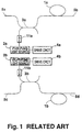
- FIG. 1 of the accompanying drawings shows a conventional optical-fiber amplifier of the type described above, the amplifier being to be used for a two-system signal line.
- reference numerals 1a, 1b designate first and second rare-earth-doped optical fibers
- 2a, 2b first and second pumping light sources
- 3a, 3b first and second multiwave-length combining and dividing devices
- 4a, 4b first and second pumping light source drive circuits
- 5a, 5b, 5c, 5d input and output terminals for signal light
- 11a, 11b first and second isolators.
- each of the first and second rare-earth-doped optical fibers 1a, 1b is a single-mode optical fiber doped of a rare earth element such as erbium (Er) and having a length of several meters to several tens meters.
- the first wavelength division multi/demultiplexing (WDM) device 3a is connected to the first rare-earth-doped optical fiber 1a.
- the wavelength division multi/demultiplexing (WDM) devices may be optical couplers.
- the first and second pumping light source 2a, 2b are semiconductor lasers having a wavelength of, for example, 1.48 ⁇ m and are driven the first and second pumping light source drive circuits 4a, 4b, respectively.
- the first rare-earth-doped optical fiber 1a assumes an inverted distribution state so that the signal light having a wavelength of 1.53 or 1.55 ⁇ m and inputted from the input and output terminal 5a for the signal light is amplified by the action of induced emission for output to the input and output terminal 5b.
- WDM wavelength division multi/demultiplexing
- the second rare-earth-doped optical fiber 1b assumes a population inversion state so that the signal light inputted from the input and output terminal 5c is amplified for output to the input and output terminal 5d.
- WDM wavelength division multi/demultiplexing
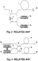
- the simplest popular optical-fiber amplifier for a single-system signal has a construction such as shown in FIG. 2.
- This known art is exemplified by Japanese Patent Laid-Open Publication No. Hei 2-241073.
- this light amplifier two sources for pumping light are combined by a combining device.
- reference numeral 1 designates a rare-earth-doped optical fiber; 2a, 2b, first and second pumping light sources; 3, a multiwavelength combining device for combining pumping light and signal light; and 8, a combining device for combining the first pumping light and the second pumping light.
- the combined light power will be 1/2 of the total light power of the first and second pumping light emitted from the first and second sources 2a, 2b. Further, since the first pumping light and the second pumping light interfere with one another, the output power of the combining device tends to fluctuate and hence to be non-stable.
- FIG. 3 shows a conventional optical amplifier for a double-system signal, which is a natural expansion of the construction of FIG. 2.
- First pumping light and second pumping light outputted from the first and second sources 2a, 2b are combined and then divided by a combining and dividing device 8, and the resulting separate parts of pumping light are inputted to first and second rare-earth-doped optical fibers 1a, 1b via first and second multiwavelength combining devices 3a, 3b.
- the output of the combining device 8 is non-stable so that the amplifying characteristic of the rare-earth-doped optical fibers 1a, 1b will not be stable.
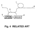
- FIG. 4 shows another conventional light amplifier, which is disclosed in "The Impact That An Er-doped Optical-Fiber Amplifier Contributes To Light Communication" by T. Shimada, Oplus E, No. 113, pp. 75-82, 1989.
- reference numeral 1 designates a rare-earth doped optical fiber; 2, a pumping light source; 3, a combining and dividing device; 4, a pumping light source drive circuit; and 5, an optical fiber serving as a signal transmission path.
- the rare-earth-doped optical fiber 1 is a single-mode optical fiber doped of a rare earth element such as erbium (Er and having a length of several meters to several tens meters.
- the combining and dividing device 3a is connected to the rare-earth-doped optical fiber 1.
- the combining and dividing device may be an optical coupler.
- the pumping light source 2 is a semiconductor laser having a wavelength of, for example, 1.48 ⁇ m and is driven the pumping light source drive circuit 4.
- the rare-earth-doped optical fiber 1 assumes an inverted distribution state so that the signal light having a wavelength of 1.53 or 1.55 ⁇ m and inputted from the optical fiber 5 is amplified by the action of induced emission.
- the rare-earth-doped optical fiber 1, the pumping light source 2, the combining and dividing device 3 and the pumping light source drive circuit 4 jointly constitute a light amplifying means.
- spontaneous emission light is emitted along with the action of light amplification.
- This spontaneous emission light produces noise, which deteriorates the signal-to-noise rate of signal light.
- the noise resulting from spontaneous emission light is exemplified by shot noise due to spontaneous emission light, beat noise between signal light and spontaneous emission light, and beat noise between one spontaneous emission light and another natural emission light.
- Spontaneous emission light is free of polarization dependency and has the component parallel to the polarization plane of signal light and that perpendicular thereto.
- the noise resulting from spontaneous emission light would deteriorate the signal-to-noise ratio of signal light. If two or more of the conventional light amplifiers are used as connected in tandem, accumulation of spontaneous emission light would bring down the saturation level of signal gain of the individual light amplifier.
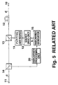
- FIG. 5 shows a convention light amplification repeating system, which is disclosed in Japanese Patent Laid-Open Publication No. Hei 3-214936.
- a subcarrier generator 15 generates a subcarrier b based on the subcarrier a, and a pumping light source drive circuit 18 drives a pumping light source 19, and a rare-earth-doped optical fiber 12 modulates, in intensity, main signal light c, whereupon main signal light d, on which the subcarrier b is superposed, is transmitted to the repeating system at the subsequent stage.
- the subcarrier b to be superposed has a frequency different from the subcarrier a.
- the subcarrier to be processed by the subcarrier processing circuit must have a different frequency for every light repeating system.
- FIG. 6 shows a typical light amplification repeating system equipped with light amplifiers and utilizing light pumping.
- the technology of this kind is disclosed in detail in, for example, Japanese Patent Laid-Open Publication No. Hei 3-214936.
- reference numerals 100a, 100b designate light end offices; 101c, 101d, 101e, light amplification repeaters; 102b, 104a light-to-electric converters; 103a, 103b, subcarrier terminals; 102 a, 104b, electric-to-light converters; 105c, 105d, 105e, 107c, 107d, 107e, light amplifiers; and 106c, 106d, 106e, subcarrier transmitters.
- the subcarrier transmitter 106c In the conventional supervisory method, assuming that an abnormality, such as a fiber breakage between the light amplifiers 105c, 105d or a fault of the light amplifier occurs, the subcarrier transmitter 106c generates a subcarrier to modulate the light amplifier 105d, which is a pumping LD, and transmits the subcarrier to the downstream side.
- the subcarrier terminal 103b discriminates the context of the transmitted subcarrier and issues an appropriate command.
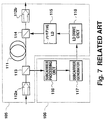
- FIG. 7 shows the conventional light amplifier and subcarrier transmitter which are shown in Japanese Patent Laid-Open-Publication No. Hei 3-214936.
- reference numeral 105 designates a light amplifier; 106, a subcarrier transmitter; 111, an erbium-doped fiber; 112a, 112b, light isolators; 113, a light branching device; 114, a light combining device; 115, an excitation LD; 116, a subcarrier processing circuit; 117, a subcarrier generator; and 118, a pumping LD drive circuit.
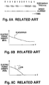
- FIGS. 8A, 8B and 8C show the signal and spectrums of the system of FIG. 7.
- the signal light is inputted to the light branching device 113 via the isolator 112a.
- the light branching device 113 branches a small quantity of the power to the subcarrier processing circuit 116 and most of the remaining power to the erbium-doped fiber 111.
- the subcarrier processing circuit 116 the state of light input to the light amplifier is detected.
- a subcarrier is generated based on information from the subcarrier processing circuit 116 and the state of operation of the light amplifier.
- the information from the subcarrier processing circuit is a breakage of input to the light amplifier when, for example, the upstream fiber happened to be cut off. What to be supervised while the light amplifier is operative may be a fault of the pumping LD.
- the pumping LD drive circuit drives the pumping LD by a current obtained by superposing the subcarrier on a bias current.
- the pumping light is modulated in intensity by the subcarrier.
- FIG. 8A schematically shows the output light from the pumping LD 115 to the light combining device 114 in FIG. 7; a signal slightly modulated by 1 to several % is superposed on a direct current.
- the gain of the light amplifier is very dependent on the pumping light power, it will be modulated as the pumping light is modulated in intensity. Consequently the envelope of signal light is modulated in intensity by the subcarrier.
- the transmission characteristic of the light amplification repeating and transmission system is a band pass characteristic; it has therefore been customary to premodulate the subcarrier by a sine wave having predetermined binary information. This concept is discussed in detail in, for example, Japanese Patent Laid-Open Publication No. Hei 3-252231 and "Control of Supervision in Light Amplification Repeating and Transmission Method" by Imai et al., Electronic Information Communication Society Spring Meeting B-944, 1992.
- FIG. 8B shows a frequency spectrum of electric power density of the output light from the pumping LD 115 in FIG. 7.
- noise would occur chiefly at the low-frequency side so that the output of the light amplifier 112b of FIG. 7 will be as indicated by the frequency spectrum of FIG. 8C. Consequently the frequency of the subcarrier deteriorates the C/N ratio.
- FIG. 9 shows the result of calculation of the C/N ratio when the modulation indices of the subcarrier is varied.
- RIN is ⁇
- the C/N ratio is determined by the spontaneous emission light of the light amplifier; thus 90 dB is obtained with a modulation index of 1%.
- the C/N ratio varies markably, compared to RIN.
- the measurement of RIN of the output light from the light amplifier shows that RIN at 5 kHz was -82 dB/Hz. Calculating the C/N ratio using this value, the C/N ratio at a modulation index of, for example, 1 %, was only 20 dB. Consequently an adequate code error cannot be achieved.
- the light power will be lowered to start generating a subcarrier, but the light power outputted from the upstream light amplifier 105d is increased progressively (the time constant at this time depends on the relaxation time of spontaneous emission from the light amplifier) so that the subcarrier processing circuit in the light amplification repeater 101e at the next stage will stop transmission of the carrier signal soon.
- the subcarrier terminal 103b When detecting any breakage of signal channel, the subcarrier terminal 103b will receive a subcarrier, indicating the fact "input is cut off", not only from the light amplification repeater 101c but also the light amplification repeater 101d. Consequently it was impossible to discriminate as to which information is correct.
- a second object of the invention is to provide an optical-fiber amplifier which can retard deterioration of the signal-to-noise ratio, causing only a limited extent of lowering of saturation level due to the cascade connection.
- a third object of the invention is to provide a light repeating system which can demodulate and sample a first subcarrier from level fluctuation of main signal light, on which the first subcarrier was superposed from the front stage, when received the main signal light and which can superpose a second subcarrier of an arbitrary frequency (including the same frequency as the first subcarrier) on main signal light or spontaneous emission light for transmission.
- a fourth object of the invention is to improve the C/N ratio of a subcarrier at the output stage of a light amplification repeater.
- a fifth object of the invention is to make it possible to detect one of light amplification repeaters at which a signal-line breakage has occured.
- an optical-fiber amplifier comprising: error-signal-generating means for inputting a light signal, on which a first subcarrier is superposed, and generating an error signal according to the difference between the level of the light signal and a predetermined reference level; constant level means for maintaining the level of the light signal at a constant level, based on the error signal outputted from the error-signal-generating means; subcarrier-processing means for detecting and processing the first subcarrier based on the error signal; and subcarrier-superposing means for generating a second subcarrier based on the process of the subcarrier processing means and for superposing the second subcarrier on the light signal maintained at the constant level by the constant level means.
- the constant level means eliminates the intensity modulation due to the first subcarrier and samples the first subcarrier from the error-signal-generating means. Since the subcarrier-superposing means superposes the second subcarrier on the main signal light, which has become to have a constant level, it is possible to superpose the second subcarrier, whose arbitrary frequency (of course, may be equal to the first subcarrier) is regardless of the frequency of the first subcarrier of the main signal light, on the main signal for transmission.
- a light amplification repeating system with a monitoring function using a light amplifier, the system comprising: error-signal-generating means for inputting a light signal, on which a first subcarrier is superposed, and for generating an error signal according to the difference between the level of the light signal and a predetermined reference level; subcarrier-processing means for detecting and processing the first subcarrier based on the error signal; and subcarrier-superposing means for generating a second subcarrier based on the process of the subcarrier-processing means and for superposing the second subcarrier on spontaneous emission light from the light amplifier.
- the spontaneous emission light from the light amplifier is utilized as the subcarrier for a supervisory signal, it is possible to transmit the subcarrier to the subsequent stage even when the main signal light is not inputted such as due to a circuit breakage.
- a light repeating system comprising: subcarrier-transmitting means for inputting part of a light signal on which a first subcarrier is superposed and for generating a second subcarrier from the first subcarrier; pumping-light-source-driving means for outputting a driving signal based on the second subcarrier outputted from the subcarrier-transmitting means; means for modulating the driving signal, which is outputted from the pumping-light-source-driving means, with a signal whose frequency is higher than that of the second subcarrier; an pumping light source to be driven by a modified driving signal outputted from the modulating means; and amplifying means for superposing the second subcarrier on the light signal, on which the first subcarrier is superposed, by pumping light from the pumping light source.
- the pumping light source is driven by the signal modulated by a frequency adequately higher than the subcarrier, it is possible to reduce the noise due to mode hopping.
- a light repeating system with a monitoring function comprising: subcarrier-transmitting means for inputting part of a light signal on which a first subcarrier is superposed and for generating a second subcarrier from the first subcarrier; pumping-light-source-driving means for outputting a driving signal based on the second subcarrier outputted from the subcarrier-transmitting means; a self-oscillation pumping light source to be driven by the driving signal outputted from the pumping-light-source-driving means; and amplifying means for superposing the second subcarrier on the light signal, on which the first subcarrier is superposed, by pumping light from the self-oscillation pumping light source.
- the pumping light having a frequency adequately higher than the subcarrier is outputted from the self-oscillating pumping light source, it is possible to reduce the noise due to mode hopping.
- a light repeating system composed of a plurality of light repeaters, each with a monitoring function, and a light end office, the sytem comprising: demodulating means located in the light end office for demodulating subcarriers transmitted from the individual light repeaters; and judging means located in the light end office for judging it abnormal when abnormal information contained in the subcarrier demodulated by the demodulating means continues for a predetermined time period or appears a predetermined number of occasions.
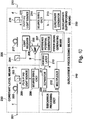
- FIG. 10 shows a light repeating system according to an embodiment using the optical fiber amplifier of the invention.
- reference numeral 201 designates an input terminal for main signal light; 202, 217, rare-earth-doped optical fibers; 203, 216, WDM optical coupler; 204, a light branching coupler; 205, a light receiver; 206, a differential amplifier; 207, a reference potential generator 208; 214, a pumping light source drive circuit; 215, a pumping light source; 210, a demodulator; 211, a separator; 212, a multiplexer; 213, a subcarrier generator; 218, an output terminal for main signal light; a, a first subcarrier; b, a second subcarrier; c, main signal light on which the first subcarrier is superposed; d, main signal light on which the second subcarrier is superposed; e, pumping light; g, a level error signal; and h, amplified light
- 225 designates an error signal generating means for inputting the light signal, on which the first subcarrier is superposed, to compare it with a predetermined reference value and for generating an error signal based on the result of comparison; 230, a constant level circuit for making an inputted light signal to be a constant level, based on the error signal; 240, a subcarrier processing means for detecting and processing the first carrier based on the error signal generated from the error signal generator 225; and 250, a subcarrier superposing means for generating a second subcarrier based on the process of the subcarrier processing means 240 and for superposing the second subcarrier on the light signal.
- the operation of the light repeating system of this embodiment will now be described with reference to FIG. 10.
- the main signal light c on which the first subcarrier a as a low-frequency signal is superposed, is inputted to the input terminal 201 from the front-stage light amplification repeating system.
- the light-branching coupler 204 branches part of the main signal light c, on which the first carrier signal a is superposed, from the input terminal 201; one of the branched output sides is connected to the rare-earth-doped optical fiber 217, while the other output side is connected to the light receiver 205 which receives part of the main signal light c.
- the light output of the pumping light source 209 is regulated by the pumping light source drive circuit 208 so as to be a predetermined constant value.
- the constant level amplifying means 230 operates so as to make the light level constant.
- the light level at the light receiver 205 also varies.
- the light receiver 205 converts the light level photo- electrically.
- the differential amplifier 206 compares the light level with the level of the reference potential generator 207 and outputs the difference in level as a level error signal g resulting from the first subcarrier a superposed on the main signal light.
- the pumping light source drive circuit 208 regulates the output level of the pumping light e of the pumping light source 209 based on the level error signal g, and the regulated light enters the rare-earth-doped optical fiber 202 from the WDM optical coupler 203.
- the rare-earth-doped optical fiber 202 is a single-mode fiber having a length of several meters to several tens of meters and doped of a rare earth element such as erbium (Er), and partly since the pumping light e of the pumping light source 209 is excited behind the WDM optical coupler 203, the rare-earth-doped optical fiber 202 causes inverted distribution so that the main signal light from the input terminal 201 is amplified by stimulated emission.
- the pumping light source drive circuit 208 of the constant level amplifying means 230 controls the pumping light source 209 in such a manner that the first subcarrier a and the level error signal g are inverted in phase, and the pumping light e is excited at the rare-earth-doped optical fiber 202, thus obtaining the amplified light h whose light level is stable.
- the subcarrier processing means 240 controls the light repeating system using the first subcarrier a, as the level error signal g of the differential amplifier 206 is demodulated by the demodulator 210, is separated by the separator 211 and is processed by the subcarrier processing circuit 220.
- the multiplexer 212 inputs the signal from the separator 211, the first subcarrier a and the signal from the subcarrier processing circuit 220, and then multiplexes these signals over the signal from the light repeating system.
- the subcarrier superposing means 250 outputs the main signal light, which the second subcarrier b is superposed on the second amplified light h stabled in a constant level in the fiber, by the same action as mentioned above, as the first subcarrier b is generated from the subcarrier generator 213 by the repeating system, as the pumping light source 215 is controlled by the pumping light source drive circuit 214 and as the pumping light f of the pumping light source 215 is excited at the rare-earth-doped optical fiber 217 behind the WDM optical coupler 216.
- the light amplification repeating system equipped with light amplifier comprises: a first optical fiber, which is doped of a light amplifying medium, for inputting main signal light, on which a first subcarrier is superposed, and for outputting a first amplified light; a first pumping light source for generating first pumping light to excite the first optical fiber; a first WDM optical coupler connected to the first optical fiber to multiplex wavelength; a first pumping light source drive circuit for driving the first pumping light source; a light-branching coupler for branching the first amplified light; a light receiver for converting the branched output light of the light-branching coupler photoelectrically; a reference potential generator for selecting a reference potential to compare an electrical signal from the light receiver with the predetermined reference value; a differential amplifier for comparing the output signals from the light receiver and the reference potential generator and for outputting a level error signal based on the result of comparison; a demodulator for inputting the level error signal, i
- the first subcarrier sampled, from the differential amplifier and for demodulating the inputted signal a second optical fiber doped of a light amplifying medium for inputting the first amplified light and for outputting second amplified light; a second pumping light source for generating second pumping light to excite the second optical fiber; a second WDM optical coupler connected to the second optical fiber for multiplexing the second excitation light over the first amplified light; a second pumping light source drive circuit for driving the second pumping light source; and a subcarrier generator connected to the second pumping light source drive circuit for superposing the second subcarrier on the second pumping light from the second pumping light source.
- the first subcarrier a and the second subcarrier b may have a common carrier frequency.
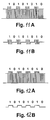
- Each of the first and second subcarriers a and b may be a carrier wave modified with supervisory information (in this case, 1, 0, 1, 0, 1...) by amplitude shift keying, as shown in FIG. 11A.
- the demodulator for demodulating the subcarrier samples a modulated signal of FIG. 11B by inputting the main signal light, on which the subcarrier is superposed, by the light receiver, then converting the inputted main signal light photoelectrically and finally transmitting the converted signal through a band-pass filter which permits only the modulated-frequency component of the subcarrier to pass. Then when the modulated signal is square-law-detected or synchronous-detected, the light amplification repeating system can obtain supervisory information.
- an alternative modulation e.g., FSK or PSK
- FSK FSK
- PSK a modulation
- FIGS. 12A and 12B show supervisory information directly modulated by PCM.
- the light amplification repeating system can obtain supervisory information in the same method as the ASK modulation.
- the subcarrier b outputted from the subcarrier generator 213 can control the pumping light source 215, totally regardless of the index of modulation of the front-stage subcarrier a.
- the main signal light c is inputted in the light amplification repeating system all the time. However, if breakage of the fiber happens to occur upstream of the light amplification repeating system or the upstream light amplification repeating system happens to be faulty, the main signal light c cannot be inputted to the light amplification repeating system. In this instance, with the system having the same construction as the previous embodiment, assuming that the pumping light from the pumping light source 215 is modulated and that the second subcarrier b is transferred with spontaneous emission light as a carrier wave, it is possible to transfer the subcarrier even in the absence of the main signal light c.
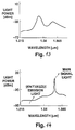
- FIG. 13 shows a spontaneous emission light spectrum of the light amplifier, when the main signal light c is not inputted
- FIG. 14 shows a spontaneous emission light spectrum of the light amplifier when the main signal light c is inputted.
- the level of the spontaneous emission light is low. But in the absence of the main signal light c inputted, no stimulated emission occurs to increase the level of the spontaneous emission light.
- the second subcarrier b should be transferred with this high-label spontaneous emission light as a carrier wave.
- the rare-earth-doped optical fiber 202, 217 is excited by backward pumping.
- the same result as this embodiment can be expected also in the case of forward pumping as shown in FIG. 15.
- Designated by 219 is a band-pass filter.
- the present inventors discovered that the intensity noise observed in the output of the light amplifier was chiefly caused by the intensity noise generated from the pumping LD.
- the intensity noise of the pumping LD modulates the gain of the light amplifier, and as a result, the intensity noise observed in the output of the light amplifier will increase.
- the main cause for the intensity noise of the pumping LD is the mode hopping noise.
- the present inventors discovered that it is possible to reduce the intensity noise of a light amplifier if this technology is adopted in the pumping LD. Specifically they discovered that there existed a great intensity noise in the pumping LD used in the conventional light amplifier and that this intensity noise modulated the gain of the light amplifier, thus causing the intensity noise of the light amplifier. If the intensity noise of the pumping LD itself is reduced, the intensity of the light amplifier will be reduced.
- FIG. 17 shows a further embodiment of this invention.
- reference numeral 301 designates an erbium-doped fiber; 302a, 302b, optical isolators; 303, a light dividing device; 304, a light combining device; 305, a pumping LD; 306, a subcarrier processing circuit; 307, a subcarrier generator; 318, a pumping light drive circuit; 309, a high-frequency oscillator; and 310, an adder.
- This binary information is premodulated by a subcarrier S c (t) expressed by equation (1) and yields a subcarrier S v (t) expressed by equation (2).
- S c (t) A cos (2pf s t + H)
- S v (t) A x a(t) cos (2pf s t + H)
- H(t) B cos (2pf r t + w)
- H(t) is a high-frequency (usually over 600 MHz) near the relaxation oscillation frequency.
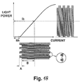
- FIG. 18 shows the relation between current and output light power of the pumping LD.
- the premodulated subcarrier is only superposed on the biasing current Ib, which is a direct current, of the pumping LD.
- the biasing current Ib which is a direct current
- a high-frequency signal far higher than the subcarrier is superposed.
- the amplitude of a high-frequency signal to be superposed should be preset in such a manner that the maximal value of the current is below the threshold current Ith of the pumping LD.
- FIG. 19A is a diagram showing the output light of a pumping LD 305 of this embodiment in comparison with the output light of the conventional pumping LD.
- the output will be as shown in FIG. 18 as excited by the current expressed by equation (4), and the relation of the typical frequency will be as shown in FIG. 19A.
- the pumping LD oscillates in various modes when the current flowing the pumping LD crosses the threshold, the average vertical mode spectrum will be in a multimode. Therefore the maximal value of intensity noise of the pumping LD is reduced, so that the intensity noise of the light amplifier also will be reduced.
- FIG. 19B shows a frequency spectrum of the output light of the pumping LD, from which it turns out that the low-frequency noise is lowered, compared to the corresponding spectrum of the conventional art.
- the spectrum of the output of the light amplification repeater will be as shown in FIG. 19C.
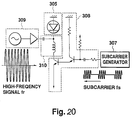
- the pumping LD 305, the subcarrier generator 307, the pumping LD drive circuit 308, the high-frequency oscillator 309 and the adder 310, all shown in FIG. 17 may be in concrete forms as shown in FIG. 20.
- the adder 310 has a T biasing
- the pumping LD drive circuit 308 is a current amplifier circuit with a Darlington transistor pair.
- FIG. 21 shows the results of measurement of relative intensity noise (RIN) of the pumping LD when a large-amplitude high-frequency modulation (superposition) takes place by a sine wave signal of 800 MHz.
- RIN relative intensity noise
- FIG. 21 shows the results of measurement of relative intensity noise (RIN) of the pumping LD when a large-amplitude high-frequency modulation (superposition) takes place by a sine wave signal of 800 MHz.
- the relative intensity noise at 5 kHz is -82 dB/Hz, which is very poor.
- by high-frequency superposition it is possible to improve the relative intensity noise at low-frequency area, i.e. -122 dB/Hz at 5 kHz.
- FIG. 22 shows the results of measurement of C/N ratio at that time.
- the modulation index was 1%
- the C/N ratio was 20 dB; but high-frequency superposition improved to 50 dB, which is enough to secure transmission quality.
- FIG. 23 shows the results of measurement of code error rate during high-frequency superposition.
- the modulation index of the subcarrier was 0.1%, an adequate code error rate of less than 10 -12 was achieved.
- the signal to superpose was a sine wave signal.
- the superposing signal may be a pulse signal with totally the same results. Since a pulse signal generator can be realized more easily than a sine wave generator, it is preferable to use a pulse signal from a view point of reducing the cost of production.
- the pulse-driving is used to save electric energy consumption, the purpose for which the frequency of a pulse signal is preset to a low value. There was proposed no technical concept suggesting the amplitude of a pulse signal. Also no report was made on the concept that the pulse-driving retards noise.
- the object of this invention is to reduce noise of the light amplifier, the purpose for which the frequency of a superposing pulse (or sine wave) signal is preset to a high-frequency (usually over 600 MHz) near relaxation oscillation of the LD. What this invention calls for is that the minimal value of the amplitude of a pulse signal is below a threshold of the pumping LD. Further in this invention, it is possible to reduce noise of the light amplifier in the low-frequence area.
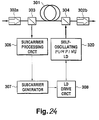
- FIG. 24 shows a further embodiment of this invention.
- Designated by 320 in FIG. 24 is a self-oscillating pumping LD, which is different from the conventional art.
- This self-oscillation phenomenon in which the LD oscillates by itself at high-frequency in the absence of a signal, was discussed in, for example, "Factor Control and Noise Reduction of Self-Oscillation in VSIS Laser” by Hayashi et al., the collection of preparatory papers for the 31st Liaison Conference on Applied Physics, page 29 M4, 1984.
- Using a self-oscillating LD it is possible to achieve the same results as those with high-frequency superposition at a frequency of several GHz, causing stable multimode oscillation.
- the output light of the self-oscillating pumping LD 320 will have the waveform of FIG. 19 according to a control signal from the pumping LD drive circuit 304 so that the intensity noise of the pumping LD is reduced to improve the transmission quality of the subcarrier. Since it does not require any high-frequency superposing circuit, simplification of the system can be realized.
- FIG. 25 shows a light end office 103b according to a fourteenth embodiment of this embodiment.
- the subcarrier converted into an electrical signal by a photoelectric converter 102b is synchronous-detected by a detector 81 and is then converted into binary information by a demodulator 82.
- a detector 83a of a decoder 83 detects carrier information bits to report to a discriminator 83b that an abnormal signal has been received.
- the discriminator 83b discriminates whether or not the number of subcarrier information bits continue for a predetermined period, or counts whether or not they continue for a predetermined number of successive frames or for a predetermined time period.
- FIG. 26 shows one example of frame format of binary information. 1 frame consists of 16 bits, every fourth bits of which are frame synchronizing bits. The subcarrier information bits are indicated by A and B in FIG. 26, and each bit will be "0" to indicate an abnormality for the fact "input is cut off". The decoder 83 judges the fact as "input is cut off" from this binary information to issue an alarm.
- FIGS. 28A through 28E are timing diagrams of individual signals of various parts of the system when the fact "input is cut off” occured.
- the input light power of the light amplifier #1 (FIG. 4) varies as shown in FIG. 28A.
- the output power of the light amplifier #1 falls instantly and then rises slowly as spontaneous emission light increases gradually, as shown in FIG. 28B.
- the rising time is determined by a relaxation time constant of spontaneous emission of the light amplifier. Having a threshold level preset between the output light power at the time of normal and the output light power at the time of "input is cut off", the light amplifier #1 detects the fact "input is cut off".
- the output light power of the next-stage light amplifier #2 of FIG. 28C varies very similary to that of FIG. 28B. In this case, since the spontaneous emission light generated from the light amplifier #1 is inputted, the output of the light amplifier #2 will become much larger than the output of the light amplifier #1, exceeding the threshold.
- the subcarrier transferred from the light amplifier #1 and decoded at its terminal portion will become “HI” when it is below the threshold level, as shown in FIG. 28D.
- the subcarrier transferred from the light amplifier #2 and decoded will produce "HI” and will then return to "LO” when it restores over the threshold, as shown in FIG. 28E. According to the measurement, this time period was about 3 ms.
- the discriminator 83b of the decoder 83 will not issue an alarm until the subcarrier information bit A will become, for example, "0" three consecutive times; this is, the result of judgement will not be issued in the absence of three consecutive coincidences. If the transmission rate of binary information is 1200 bits/s, it will take the time of 16x3 bits, i.e. 40 ms, until an alarm is issued. Even when an error subcarrier has arrived from light amplifier #2 for a period of about 3 ms, the decoder does not judge it as error. It is therefore possible to judge the light amplifier #1 correctly as having issued "input is cut off".
- the subcarriers are digital.
- analog subcarrier may be used.
- a circuit-breakage-detecting-signal separator for analog signal separates a circuit-breakage signal in response to the sampling of subcarrier information bits at the decoder of FIG. 25. Unlike the case of digital sub-carriers, only when the separated analog circuit-breakage signal has continued for a predetermined time period, it will be judged that there has occured a fault.
- the system since the system includes the excitation signal driving and adding means for modulating a bias signal, whose intensity is modulated by a subcarrier, with a high-frequency sine wave or pulse, and the pumping light means for generating pumping light to be excited to be by the output of the pumping signal driving and adding means, or since the system includes the pumping signal driving means for generating a bias signal whose intensity is modulated by a subcarrier, and the self-oscillating pumping light generating means for generating pumping light to be modulated by the output of the pumping signal driving means, it is possible to reduce noise contained in the carrier signal and also to reduce intensity noise of the light amplification repeater.
- the decoder for decoding a subcarrier from each light amplification repeater includes the discriminating means for detecting a plurality of successive codes from information bits of the subcarriers from the individual amplification repeaters to judge it as back error, it is possible to detect an abnormal with improved accuracy.
Abstract
error-signal-generating means for inputting a light signal, on which a first subcarrier is superposed, and generating an error signal according to the difference between the level of the light signal and a predetermined reference level; constant level means for maintaining the level of the light signal at a constant level, based on the error signal outputted from the error-signal-generating means; subcarrier-processing means for detecting and processing the first subcarrier based on the error signal; and subcarrier-superposing means for generating a second subcarrier based on the process of the subcarrier processing means and for superposing the second subcarrier on the light signal maintained at the constant level by the constant level means.
Description
- This invention relates to an optical-fiber amplifier which is to be used in a light communication system and uses an optical fiber doped of a rare earth element.
- FIG. 1 of the accompanying drawings shows a conventional optical-fiber amplifier of the type described above, the amplifier being to be used for a two-system signal line. In FIG. 1,
reference numerals - In operation, each of the first and second rare-earth-doped
optical fibers device 3a is connected to the first rare-earth-dopedoptical fiber 1a. The wavelength division multi/demultiplexing (WDM) devices may be optical couplers. The first and secondpumping light source source drive circuits pumping light source 2a is inputted to the first rare-earth-dopedoptical fiber 1a via the first wavelength division multi/demultiplexing (WDM)device 3a, the first rare-earth-dopedoptical fiber 1a assumes an inverted distribution state so that the signal light having a wavelength of 1.53 or 1.55 µm and inputted from the input andoutput terminal 5a for the signal light is amplified by the action of induced emission for output to the input andoutput terminal 5b. Likewise, when the second pumping light outputted from the secondpumping light source 2b is inputted to the second rare-earth-dopedoptical fiber 1b via the second wavelength division multi/demultiplexing (WDM)device 3b, the second rare-earth-dopedoptical fiber 1b assumes a population inversion state so that the signal light inputted from the input and output terminal 5c is amplified for output to the input andoutput terminal 5d. With this conventional arrangement, it is impossible to improve the reliability of this type optical-fiber light amplifier. - The simplest popular optical-fiber amplifier for a single-system signal has a construction such as shown in FIG. 2. This known art is exemplified by Japanese Patent Laid-Open Publication No. Hei 2-241073. In this light amplifier, two sources for pumping light are combined by a combining device. In FIG. 2,
reference numeral 1 designates a rare-earth-doped optical fiber; 2a, 2b, first and second pumping light sources; 3, a multiwavelength combining device for combining pumping light and signal light; and 8, a combining device for combining the first pumping light and the second pumping light. However, when the first pumping light and the second pumping light are combined by the combiningdevice 8, the combined light power will be 1/2 of the total light power of the first and second pumping light emitted from the first andsecond sources - FIG. 3 shows a conventional optical amplifier for a double-system signal, which is a natural expansion of the construction of FIG. 2. First pumping light and second pumping light outputted from the first and
second sources device 8, and the resulting separate parts of pumping light are inputted to first and second rare-earth-dopedoptical fibers multiwavelength combining devices device 8 is non-stable so that the amplifying characteristic of the rare-earth-dopedoptical fibers - With this conventional arrangement, the level of pumping light to be inputted to the amplifying media will not be stable.
- FIG. 4 shows another conventional light amplifier, which is disclosed in "The Impact That An Er-doped Optical-Fiber Amplifier Contributes To Light Communication" by T. Shimada, Oplus E, No. 113, pp. 75-82, 1989. In FIG. 4,
reference numeral 1 designates a rare-earth doped optical fiber; 2, a pumping light source; 3, a combining and dividing device; 4, a pumping light source drive circuit; and 5, an optical fiber serving as a signal transmission path. - In operation, the rare-earth-doped
optical fiber 1 is a single-mode optical fiber doped of a rare earth element such as erbium (Er and having a length of several meters to several tens meters. The combining and dividingdevice 3a is connected to the rare-earth-dopedoptical fiber 1. The combining and dividing device may be an optical coupler. Thepumping light source 2 is a semiconductor laser having a wavelength of, for example, 1.48 µm and is driven the pumping lightsource drive circuit 4. When several mW to several tens mW of pumping light outputted from the pumpinglight source 2 is inputted to the rare-earth-dopedoptical fiber 1 via the combining and dividingdevice 3, the rare-earth-dopedoptical fiber 1 assumes an inverted distribution state so that the signal light having a wavelength of 1.53 or 1.55 µm and inputted from theoptical fiber 5 is amplified by the action of induced emission. The rare-earth-dopedoptical fiber 1, the pumpinglight source 2, the combining and dividingdevice 3 and the pumping lightsource drive circuit 4 jointly constitute a light amplifying means. - In the light amplifier utilizing the action of stimulated emission, spontaneous emission light is emitted along with the action of light amplification. This spontaneous emission light produces noise, which deteriorates the signal-to-noise rate of signal light. The noise resulting from spontaneous emission light is exemplified by shot noise due to spontaneous emission light, beat noise between signal light and spontaneous emission light, and beat noise between one spontaneous emission light and another natural emission light. Spontaneous emission light is free of polarization dependency and has the component parallel to the polarization plane of signal light and that perpendicular thereto.
- Further, when two or more light amplifiers are to be used as connected in tandem, accumulation of spontaneous emission light brings down the saturation level of signal gain of the light amplifier.
- With the conventional light amplifier, the noise resulting from spontaneous emission light would deteriorate the signal-to-noise ratio of signal light. If two or more of the conventional light amplifiers are used as connected in tandem, accumulation of spontaneous emission light would bring down the saturation level of signal gain of the individual light amplifier.
- FIG. 5 shows a convention light amplification repeating system, which is disclosed in Japanese Patent Laid-Open Publication No. Hei 3-214936.
- In this conventional light amplification repeating system, when the main signal light c, on which a subcarrier a is superposed, is inputted from a main signal
light input terminal 11, the main signal light c is branched by alight branching coupler 14. Part of the branched main signal light c is inputted to asubcarrier processing circuit 20 where a process takes place based on the subcarrier a. Asubcarrier generator 15 generates a subcarrier b based on the subcarrier a, and a pumping lightsource drive circuit 18 drives apumping light source 19, and a rare-earth-dopedoptical fiber 12 modulates, in intensity, main signal light c, whereupon main signal light d, on which the subcarrier b is superposed, is transmitted to the repeating system at the subsequent stage. At that time the subcarrier b to be superposed has a frequency different from the subcarrier a. - With this arrangement, the subcarrier to be processed by the subcarrier processing circuit must have a different frequency for every light repeating system.
- FIG. 6 shows a typical light amplification repeating system equipped with light amplifiers and utilizing light pumping. The technology of this kind is disclosed in detail in, for example, Japanese Patent Laid-Open Publication No. Hei 3-214936. In FIG. 6,
reference numerals - In the conventional supervisory method, assuming that an abnormality, such as a fiber breakage between the
light amplifiers subcarrier transmitter 106c generates a subcarrier to modulate thelight amplifier 105d, which is a pumping LD, and transmits the subcarrier to the downstream side. Thesubcarrier terminal 103b discriminates the context of the transmitted subcarrier and issues an appropriate command. - FIG. 7 shows the conventional light amplifier and subcarrier transmitter which are shown in Japanese Patent Laid-Open-Publication No. Hei 3-214936. In FIG. 7,
reference numeral 105 designates a light amplifier; 106, a subcarrier transmitter; 111, an erbium-doped fiber; 112a, 112b, light isolators; 113, a light branching device; 114, a light combining device; 115, an excitation LD; 116, a subcarrier processing circuit; 117, a subcarrier generator; and 118, a pumping LD drive circuit. FIGS. 8A, 8B and 8C show the signal and spectrums of the system of FIG. 7. - In operation, the signal light is inputted to the
light branching device 113 via theisolator 112a. Thelight branching device 113 branches a small quantity of the power to thesubcarrier processing circuit 116 and most of the remaining power to the erbium-dopedfiber 111. In thesubcarrier processing circuit 116, the state of light input to the light amplifier is detected. In thesubcarrier generator 117, a subcarrier is generated based on information from thesubcarrier processing circuit 116 and the state of operation of the light amplifier. The information from the subcarrier processing circuit is a breakage of input to the light amplifier when, for example, the upstream fiber happened to be cut off. What to be supervised while the light amplifier is operative may be a fault of the pumping LD. The pumping LD drive circuit drives the pumping LD by a current obtained by superposing the subcarrier on a bias current. The pumping light is modulated in intensity by the subcarrier. - FIG. 8A schematically shows the output light from the pumping
LD 115 to thelight combining device 114 in FIG. 7; a signal slightly modulated by 1 to several % is superposed on a direct current. - Since the gain of the light amplifier is very dependent on the pumping light power, it will be modulated as the pumping light is modulated in intensity. Consequently the envelope of signal light is modulated in intensity by the subcarrier.
- The transmission characteristic of the light amplification repeating and transmission system is a band pass characteristic; it has therefore been customary to premodulate the subcarrier by a sine wave having predetermined binary information. This concept is discussed in detail in, for example, Japanese Patent Laid-Open Publication No. Hei 3-252231 and "Control of Supervision in Light Amplification Repeating and Transmission Method" by Imai et al., Electronic Information Communication Society Spring Meeting B-944, 1992.
- Transmission of a subcarrier requires a high transmission quality. On many occasions the quality of signal is evaluated on the carrier/noise ratio (C/N ratio). The present inventors discovered that the main factor to deteriorate the C/N ratio of a subcarrier is the intensity noise produced from the light amplifier. The intensity noise is expressed quantitatively by relative intensity noise (RIN).
- FIG. 8B shows a frequency spectrum of electric power density of the output light from the pumping
LD 115 in FIG. 7. As shown in FIG. 8B, in the conventional excitation in which a direct current is modulated by a subcarrier, noise would occur chiefly at the low-frequency side so that the output of thelight amplifier 112b of FIG. 7 will be as indicated by the frequency spectrum of FIG. 8C. Consequently the frequency of the subcarrier deteriorates the C/N ratio. - FIG. 9 shows the result of calculation of the C/N ratio when the modulation indices of the subcarrier is varied. When RIN is α, the C/N ratio is determined by the spontaneous emission light of the light amplifier; thus 90 dB is obtained with a modulation index of 1%. However, the C/N ratio varies markably, compared to RIN. In fact, the measurement of RIN of the output light from the light amplifier shows that RIN at 5 kHz was -82 dB/Hz. Calculating the C/N ratio using this value, the C/N ratio at a modulation index of, for example, 1 %, was only 20 dB. Consequently an adequate code error cannot be achieved.
- The mode of supervising operation for any breakage of communication channel in the foregoing circuit will now be discussed.
- Assuming that the fiber between the
light amplifiers device 113 in thesubcarrier transmitter 106d of thelight amplification repeater 101d is lowered from a threshold preset in thesubcarrier processing circuit 116. Instantly thesubcarrier generator 117 generates a subcarrier, which will modulate the pumping LD of thelight amplifier 105d and will then be transmitted to the downstream side. - Also in the
light amplification repeater 101e at the next stage, the light power will be lowered to start generating a subcarrier, but the light power outputted from the upstreamlight amplifier 105d is increased progressively (the time constant at this time depends on the relaxation time of spontaneous emission from the light amplifier) so that the subcarrier processing circuit in thelight amplification repeater 101e at the next stage will stop transmission of the carrier signal soon. - With this light amplification repeater, the C/N ratio of a supervisory signal would be lowered to deteriorate the quality of the supervisory signal.
- When detecting any breakage of signal channel, the
subcarrier terminal 103b will receive a subcarrier, indicating the fact "input is cut off", not only from thelight amplification repeater 101c but also thelight amplification repeater 101d. Consequently it was impossible to discriminate as to which information is correct. - It is therefore a first object of this invention to provide a high-reliability optical-fiber amplifier which does not cause fluctuation of light power level of an output signal even when output light level fluctuation of pumping light sources or cutting-off of one of the pumping light sources occurs.
- A second object of the invention is to provide an optical-fiber amplifier which can retard deterioration of the signal-to-noise ratio, causing only a limited extent of lowering of saturation level due to the cascade connection.
- A third object of the invention is to provide a light repeating system which can demodulate and sample a first subcarrier from level fluctuation of main signal light, on which the first subcarrier was superposed from the front stage, when received the main signal light and which can superpose a second subcarrier of an arbitrary frequency (including the same frequency as the first subcarrier) on main signal light or spontaneous emission light for transmission.
- A fourth object of the invention is to improve the C/N ratio of a subcarrier at the output stage of a light amplification repeater.
- A fifth object of the invention is to make it possible to detect one of light amplification repeaters at which a signal-line breakage has occured.
- According to an aspect of the invention, there is provided an optical-fiber amplifier comprising: error-signal-generating means for inputting a light signal, on which a first subcarrier is superposed, and generating an error signal according to the difference between the level of the light signal and a predetermined reference level; constant level means for maintaining the level of the light signal at a constant level, based on the error signal outputted from the error-signal-generating means; subcarrier-processing means for detecting and processing the first subcarrier based on the error signal; and subcarrier-superposing means for generating a second subcarrier based on the process of the subcarrier processing means and for superposing the second subcarrier on the light signal maintained at the constant level by the constant level means.
- The constant level means eliminates the intensity modulation due to the first subcarrier and samples the first subcarrier from the error-signal-generating means. Since the subcarrier-superposing means superposes the second subcarrier on the main signal light, which has become to have a constant level, it is possible to superpose the second subcarrier, whose arbitrary frequency (of course, may be equal to the first subcarrier) is regardless of the frequency of the first subcarrier of the main signal light, on the main signal for transmission.
- According to a further aspect of the invention, there is provided a light amplification repeating system with a monitoring function using a light amplifier, the system comprising: error-signal-generating means for inputting a light signal, on which a first subcarrier is superposed, and for generating an error signal according to the difference between the level of the light signal and a predetermined reference level; subcarrier-processing means for detecting and processing the first subcarrier based on the error signal; and subcarrier-superposing means for generating a second subcarrier based on the process of the subcarrier-processing means and for superposing the second subcarrier on spontaneous emission light from the light amplifier.
- Since the spontaneous emission light from the light amplifier is utilized as the subcarrier for a supervisory signal, it is possible to transmit the subcarrier to the subsequent stage even when the main signal light is not inputted such as due to a circuit breakage.
- According to a still further aspect of the invention, there is provided a light repeating system comprising: subcarrier-transmitting means for inputting part of a light signal on which a first subcarrier is superposed and for generating a second subcarrier from the first subcarrier; pumping-light-source-driving means for outputting a driving signal based on the second subcarrier outputted from the subcarrier-transmitting means; means for modulating the driving signal, which is outputted from the pumping-light-source-driving means, with a signal whose frequency is higher than that of the second subcarrier; an pumping light source to be driven by a modified driving signal outputted from the modulating means; and amplifying means for superposing the second subcarrier on the light signal, on which the first subcarrier is superposed, by pumping light from the pumping light source.
- Since the pumping light source is driven by the signal modulated by a frequency adequately higher than the subcarrier, it is possible to reduce the noise due to mode hopping.
- According to still further aspect of the invention, there is provided a light repeating system with a monitoring function, comprising: subcarrier-transmitting means for inputting part of a light signal on which a first subcarrier is superposed and for generating a second subcarrier from the first subcarrier; pumping-light-source-driving means for outputting a driving signal based on the second subcarrier outputted from the subcarrier-transmitting means; a self-oscillation pumping light source to be driven by the driving signal outputted from the pumping-light-source-driving means; and amplifying means for superposing the second subcarrier on the light signal, on which the first subcarrier is superposed, by pumping light from the self-oscillation pumping light source.
- Since the pumping light having a frequency adequately higher than the subcarrier is outputted from the self-oscillating pumping light source, it is possible to reduce the noise due to mode hopping.
- According to a still further aspect of the invention, there is provided a light repeating system composed of a plurality of light repeaters, each with a monitoring function, and a light end office, the sytem comprising: demodulating means located in the light end office for demodulating subcarriers transmitted from the individual light repeaters; and judging means located in the light end office for judging it abnormal when abnormal information contained in the subcarrier demodulated by the demodulating means continues for a predetermined time period or appears a predetermined number of occasions.
-
- FIG. 1 is a diagram showing an optical-fiber amplifier of the related art;
- FIG. 2 is a diagram showing a first system of optical-fiber amplifier of the related art;
- FIG. 3 is a diagram showing a second system of optical-fiber amplifier of the related art;
- FIG. 4 is a diagram showing another optical-fiber amplifier of the related art;
- FIG. 5 is a light repeating system of the related art;
- FIG. 6 is a block diagram showing a light amplification repeating and transmitting system of the related art;
- FIG. 7 is a block diagram showing a light amplification repeater of the related art;
- FIG. 8A is a diagram showing the output light of an excitation laser diode (LD) of the related art;
- FIGS. 8B and 8C are graphs showing output light spectrums of pumping LD of the related art;
- FIG. 9 is a graph showing the C/N ratio of a subcarrier according to the related art;
- FIG. 10 is a block diagram showing a light repeating system using an optical fiber amplifier according to an embodiment of the invention;
- FIGS. 11A and 11B are diagrams illustrating the operation of the light repeating system when a subcarrier is modulated by amplitude shift keying;
- FIGS. 12A and 12B are diagrams illustrating the operation of the light repeating system when a subcarrier is a base-band PCM signal;
- FIG. 13 is a graph showing a spontaneous emission light spectrum of the light amplifier when a main signal is not inputted;
- FIG. 14 is a graph showing a spontaneous emission light spectrum of the light amplifier when a main signal is inputted;
- FIG. 15 is a block diagram showing a modified light repeating system of the embodiment of the invention;
- FIG. 16 is a block diagram showing another modified light repeating system of the embodiment of the invention;
- FIG. 17 is a diagram showing a pumping LD according to a further embodiment of the invention;
- FIG. 18 is a graph showing an input/output characteristic of the pumping LD of the embodiment according to FIG. 17;
- FIG. 19A is a diagram showing output light of the pumping LD of the embodiment according to FIG. 17;
- FIGS. 19B and 19C are graphs showing output light spectrums of the pumping LD of the embodiment according to FIG. 17;
- FIG. 20 is a circuit diagram showing the details of the pumping LD of the embodiment according to FIG. 17;
- FIG. 21 is a graph showing the result of measurement of intensity noise according to the pumping LD of the embodiment according to FIG. 17;
- FIG. 22 is a graph showing the C/N ratio of subcarrier according to the pumping LD of the embodiment according to FIG. 17;
- FIG. 23 is a graph showing the code error rate of subcarrier according to the pumping LD of the embodiment according to FIG. 17;
- FIG. 24 is a diagram showing a pumping LD according to a further embodiment of the invention;
- FIG. 25 is a block diagram showing a light end office according to a further embodiment of the invention;
- FIG. 26 is a diagram showing a frame format of binary information according to the light end office of the embodiment according to FIG. 25;
- FIG. 27 is a system diagram of the light end office of the embodiment according to FIG. 25; and
- FIGS. 28A through 28E are timing diagrams of the light end office of the embodiment according to FIG. 25.
- Fig. 10 shows a light repeating system according to an embodiment using the optical fiber amplifier of the invention. In FIG. 10,
reference numeral 201 designates an input terminal for main signal light; 202, 217, rare-earth-doped optical fibers; 203, 216, WDM optical coupler; 204, a light branching coupler; 205, a light receiver; 206, a differential amplifier; 207, a referencepotential generator 208; 214, a pumping light source drive circuit; 215, a pumping light source; 210, a demodulator; 211, a separator; 212, a multiplexer; 213, a subcarrier generator; 218, an output terminal for main signal light; a, a first subcarrier; b, a second subcarrier; c, main signal light on which the first subcarrier is superposed; d, main signal light on which the second subcarrier is superposed; e, pumping light; g, a level error signal; and h, amplified light. - Further, 225 designates an error signal generating means for inputting the light signal, on which the first subcarrier is superposed, to compare it with a predetermined reference value and for generating an error signal based on the result of comparison; 230, a constant level circuit for making an inputted light signal to be a constant level, based on the error signal; 240, a subcarrier processing means for detecting and processing the first carrier based on the error signal generated from the
error signal generator 225; and 250, a subcarrier superposing means for generating a second subcarrier based on the process of the subcarrier processing means 240 and for superposing the second subcarrier on the light signal. - The operation of the light repeating system of this embodiment will now be described with reference to FIG. 10. The main signal light c, on which the first subcarrier a as a low-frequency signal is superposed, is inputted to the
input terminal 201 from the front-stage light amplification repeating system. The light-branchingcoupler 204 branches part of the main signal light c, on which the first carrier signal a is superposed, from theinput terminal 201; one of the branched output sides is connected to the rare-earth-dopedoptical fiber 217, while the other output side is connected to thelight receiver 205 which receives part of the main signal light c. When the light level of the main signal light c, on which the first subcarrier a is superposed, is constant, the light output of the pumpinglight source 209 is regulated by the pumping lightsource drive circuit 208 so as to be a predetermined constant value. But, for example, when the main signal light c is modified intensely with the first subcarrier a, i.e. a low-frequency signal, the light level of the main signal light c will not be constant; in this instance, the constant level amplifying means 230 operates so as to make the light level constant. As the light level varies, the light level at thelight receiver 205 also varies. Thelight receiver 205 converts the light level photo- electrically. Meanwhile thedifferential amplifier 206 compares the light level with the level of the referencepotential generator 207 and outputs the difference in level as a level error signal g resulting from the first subcarrier a superposed on the main signal light. - The pumping light
source drive circuit 208 regulates the output level of the pumping light e of the pumpinglight source 209 based on the level error signal g, and the regulated light enters the rare-earth-dopedoptical fiber 202 from the WDMoptical coupler 203. Partly since the rare-earth-dopedoptical fiber 202 is a single-mode fiber having a length of several meters to several tens of meters and doped of a rare earth element such as erbium (Er), and partly since the pumping light e of the pumpinglight source 209 is excited behind the WDMoptical coupler 203, the rare-earth-dopedoptical fiber 202 causes inverted distribution so that the main signal light from theinput terminal 201 is amplified by stimulated emission. As a result, the pumping lightsource drive circuit 208 of the constant level amplifying means 230 controls the pumpinglight source 209 in such a manner that the first subcarrier a and the level error signal g are inverted in phase, and the pumping light e is excited at the rare-earth-dopedoptical fiber 202, thus obtaining the amplified light h whose light level is stable. - The subcarrier processing means 240 controls the light repeating system using the first subcarrier a, as the level error signal g of the
differential amplifier 206 is demodulated by thedemodulator 210, is separated by theseparator 211 and is processed by thesubcarrier processing circuit 220. - The
multiplexer 212 inputs the signal from theseparator 211, the first subcarrier a and the signal from thesubcarrier processing circuit 220, and then multiplexes these signals over the signal from the light repeating system. - The subcarrier superposing means 250 outputs the main signal light, which the second subcarrier b is superposed on the second amplified light h stabled in a constant level in the fiber, by the same action as mentioned above, as the first subcarrier b is generated from the
subcarrier generator 213 by the repeating system, as the pumpinglight source 215 is controlled by the pumping lightsource drive circuit 214 and as the pumping light f of the pumpinglight source 215 is excited at the rare-earth-dopedoptical fiber 217 behind the WDMoptical coupler 216. - As mentioned above, according to this embodiment, the light amplification repeating system equipped with light amplifier comprises: a first optical fiber, which is doped of a light amplifying medium, for inputting main signal light, on which a first subcarrier is superposed, and for outputting a first amplified light; a first pumping light source for generating first pumping light to excite the first optical fiber; a first WDM optical coupler connected to the first optical fiber to multiplex wavelength; a first pumping light source drive circuit for driving the first pumping light source; a light-branching coupler for branching the first amplified light; a light receiver for converting the branched output light of the light-branching coupler photoelectrically; a reference potential generator for selecting a reference potential to compare an electrical signal from the light receiver with the predetermined reference value; a differential amplifier for comparing the output signals from the light receiver and the reference potential generator and for outputting a level error signal based on the result of comparison; a demodulator for inputting the level error signal, i.e. the first subcarrier sampled, from the differential amplifier and for demodulating the inputted signal; a second optical fiber doped of a light amplifying medium for inputting the first amplified light and for outputting second amplified light; a second pumping light source for generating second pumping light to excite the second optical fiber; a second WDM optical coupler connected to the second optical fiber for multiplexing the second excitation light over the first amplified light; a second pumping light source drive circuit for driving the second pumping light source; and a subcarrier generator connected to the second pumping light source drive circuit for superposing the second subcarrier on the second pumping light from the second pumping light source.
- In this case, the first subcarrier a and the second subcarrier b may have a common carrier frequency.
- Each of the first and second subcarriers a and b may be a carrier wave modified with supervisory information (in this case, 1, 0, 1, 0, 1...) by amplitude shift keying, as shown in FIG. 11A. The demodulator for demodulating the subcarrier samples a modulated signal of FIG. 11B by inputting the main signal light, on which the subcarrier is superposed, by the light receiver, then converting the inputted main signal light photoelectrically and finally transmitting the converted signal through a band-pass filter which permits only the modulated-frequency component of the subcarrier to pass. Then when the modulated signal is square-law-detected or synchronous-detected, the light amplification repeating system can obtain supervisory information. Of course, an alternative modulation (e.g., FSK or PSK) may be used.
- FIGS. 12A and 12B show supervisory information directly modulated by PCM. The light amplification repeating system can obtain supervisory information in the same method as the ASK modulation.
- According to this embodiment, since the light repeating system has a second light amplifier for modulation, the subcarrier b outputted from the
subcarrier generator 213 can control the pumpinglight source 215, totally regardless of the index of modulation of the front-stage subcarrier a. - In this embodiment, the main signal light c is inputted in the light amplification repeating system all the time. However, if breakage of the fiber happens to occur upstream of the light amplification repeating system or the upstream light amplification repeating system happens to be faulty, the main signal light c cannot be inputted to the light amplification repeating system. In this instance, with the system having the same construction as the previous embodiment, assuming that the pumping light from the pumping
light source 215 is modulated and that the second subcarrier b is transferred with spontaneous emission light as a carrier wave, it is possible to transfer the subcarrier even in the absence of the main signal light c. - FIG. 13 shows a spontaneous emission light spectrum of the light amplifier, when the main signal light c is not inputted, and FIG. 14 shows a spontaneous emission light spectrum of the light amplifier when the main signal light c is inputted. In the presence of the main signal light c inputted, since the energy of the light amplifier is used in amplification of the main signal light c, the level of the spontaneous emission light is low. But in the absence of the main signal light c inputted, no stimulated emission occurs to increase the level of the spontaneous emission light. When the main signal light c is cut off, the second subcarrier b should be transferred with this high-label spontaneous emission light as a carrier wave.
- In this embodiment, the rare-earth-doped
optical fiber - Further, in this embodiment, two WDM couplers are used. Alternatively the same result can be expected even with a single WDM coupler.
- It is a common knowledge that it is possible to reduce the intensity noise, which is due to the mode hopping, of an LD by superposing a large-amplitude high-frequency signal on the LD. This concept utilizes the characteristic that the LD oxcillates pulses when the bias current of the LD crosses a threshold; at that time, the LD oscillates in various modes so that the mode hopping is retarded.
- The present inventors discovered that the intensity noise observed in the output of the light amplifier was chiefly caused by the intensity noise generated from the pumping LD. The intensity noise of the pumping LD modulates the gain of the light amplifier, and as a result, the intensity noise observed in the output of the light amplifier will increase. The main cause for the intensity noise of the pumping LD is the mode hopping noise.
- As the vertical mode of an LD hops to the next mode due to the change such as of temperature, various modes oscillate competively, causing the intensity noise. This phenomenon was discussed in detail in, for example, "Fundamentals of Semiconductor Laser" edited by the Japan Applied Physics Society, published 1987 from Ohm Co., Ltd. Mode hopping noise occurs markably in the low-frequency area in particular. Since the subcarrier has only a very low-frequency band of 1 to 100 kHz, it will be affected very much by this kind of intensity noise.
- The present inventors discovered that it is possible to reduce the intensity noise of a light amplifier if this technology is adopted in the pumping LD. Specifically they discovered that there existed a great intensity noise in the pumping LD used in the conventional light amplifier and that this intensity noise modulated the gain of the light amplifier, thus causing the intensity noise of the light amplifier. If the intensity noise of the pumping LD itself is reduced, the intensity of the light amplifier will be reduced.
- Following are embodiments described in connection with these discoveries.
- FIG. 17 shows a further embodiment of this invention. In FIG. 17,
reference numeral 301 designates an erbium-doped fiber; 302a, 302b, optical isolators; 303, a light dividing device; 304, a light combining device; 305, a pumping LD; 306, a subcarrier processing circuit; 307, a subcarrier generator; 318, a pumping light drive circuit; 309, a high-frequency oscillator; and 310, an adder. - In operation, the
subcarrier generator 307 generates binary information a(t) [= 1 or 0] upon receipt of information from thesubcarrier processing circuit 306. This binary information is premodulated by a subcarrier Sc(t) expressed by equation (1) and yields a subcarrier Sv(t) expressed by equation (2).
- The subcarrier Sv(t), which is the output of the pumping LD drive circuit of FIG. 17, is added to the output waveform of the high-frequency oscillator, which generates a large-width high-frequency expressed by equation (3), by an
adder 310.
- H(t) is a high-frequency (usually over 600 MHz) near the relaxation oscillation frequency.
- The high-frequency-modulated wave, which is the output of the
adder 310, is superposed on the bias current Ib of thepumping LD 305. Finally a current I(t) flowing in the pumping LD is expressed by equation (4).
- The maximal value of the bias current is below a threshold current of the pumping LD. This condition is expressed by equation (5).

- FIG. 18 shows the relation between current and output light power of the pumping LD. In the conventional art, the premodulated subcarrier is only superposed on the biasing current Ib, which is a direct current, of the pumping LD. Whereas in this embodiment, a high-frequency signal far higher than the subcarrier is superposed. The amplitude of a high-frequency signal to be superposed should be preset in such a manner that the maximal value of the current is below the threshold current Ith of the pumping LD.
- FIG. 19A is a diagram showing the output light of a
pumping LD 305 of this embodiment in comparison with the output light of the conventional pumping LD. The output will be as shown in FIG. 18 as excited by the current expressed by equation (4), and the relation of the typical frequency will be as shown in FIG. 19A. - As mentioned above, since the pumping LD oscillates in various modes when the current flowing the pumping LD crosses the threshold, the average vertical mode spectrum will be in a multimode. Therefore the maximal value of intensity noise of the pumping LD is reduced, so that the intensity noise of the light amplifier also will be reduced.
- FIG. 19B shows a frequency spectrum of the output light of the pumping LD, from which it turns out that the low-frequency noise is lowered, compared to the corresponding spectrum of the conventional art. As a result, the spectrum of the output of the light amplification repeater will be as shown in FIG. 19C.
- The
pumping LD 305, thesubcarrier generator 307, the pumpingLD drive circuit 308, the high-frequency oscillator 309 and theadder 310, all shown in FIG. 17 may be in concrete forms as shown in FIG. 20. In the circuit of FIG. 20, theadder 310 has a T biasing, and the pumpingLD drive circuit 308 is a current amplifier circuit with a Darlington transistor pair. - FIG. 21 shows the results of measurement of relative intensity noise (RIN) of the pumping LD when a large-amplitude high-frequency modulation (superposition) takes place by a sine wave signal of 800 MHz. In the absence of high-frequency modulation (superposition), the relative intensity noise at 5 kHz is -82 dB/Hz, which is very poor. Whereas, by high-frequency superposition, it is possible to improve the relative intensity noise at low-frequency area, i.e. -122 dB/Hz at 5 kHz.
- FIG. 22 shows the results of measurement of C/N ratio at that time. When the modulation index was 1%, the C/N ratio was 20 dB; but high-frequency superposition improved to 50 dB, which is enough to secure transmission quality.
- FIG. 23 shows the results of measurement of code error rate during high-frequency superposition. When the modulation index of the subcarrier was 0.1%, an adequate code error rate of less than 10-12 was achieved.
- Thus the usefulness of this invention was demonstrated.
- In this embodiment, the signal to superpose was a sine wave signal. But the superposing signal may be a pulse signal with totally the same results. Since a pulse signal generator can be realized more easily than a sine wave generator, it is preferable to use a pulse signal from a view point of reducing the cost of production.
- It is currently known to drive the pumping LD by pulses at a frequency of about 100 kHz. This embodiment utilizes a technical concept that is totally different from this known art. The pulse-driving is used to save electric energy consumption, the purpose for which the frequency of a pulse signal is preset to a low value. There was proposed no technical concept suggesting the amplitude of a pulse signal. Also no report was made on the concept that the pulse-driving retards noise. Whereas the object of this invention is to reduce noise of the light amplifier, the purpose for which the frequency of a superposing pulse (or sine wave) signal is preset to a high-frequency (usually over 600 MHz) near relaxation oscillation of the LD. What this invention calls for is that the minimal value of the amplitude of a pulse signal is below a threshold of the pumping LD. Further in this invention, it is possible to reduce noise of the light amplifier in the low-frequence area.
- FIG. 24 shows a further embodiment of this invention. Designated by 320 in FIG. 24 is a self-oscillating pumping LD, which is different from the conventional art. This self-oscillation phenomenon, in which the LD oscillates by itself at high-frequency in the absence of a signal, was discussed in, for example, "Factor Control and Noise Reduction of Self-Oscillation in VSIS Laser" by Hayashi et al., the collection of preparatory papers for the 31st Liaison Conference on Applied Physics, page 29 M4, 1984. Using a self-oscillating LD, it is possible to achieve the same results as those with high-frequency superposition at a frequency of several GHz, causing stable multimode oscillation. As a result, the output light of the self-oscillating
pumping LD 320 will have the waveform of FIG. 19 according to a control signal from the pumpingLD drive circuit 304 so that the intensity noise of the pumping LD is reduced to improve the transmission quality of the subcarrier. Since it does not require any high-frequency superposing circuit, simplification of the system can be realized. - FIG. 25 shows a
light end office 103b according to a fourteenth embodiment of this embodiment. The subcarrier converted into an electrical signal by aphotoelectric converter 102b is synchronous-detected by adetector 81 and is then converted into binary information by ademodulator 82. - A
detector 83a of adecoder 83 detects carrier information bits to report to adiscriminator 83b that an abnormal signal has been received. Thediscriminator 83b discriminates whether or not the number of subcarrier information bits continue for a predetermined period, or counts whether or not they continue for a predetermined number of successive frames or for a predetermined time period. FIG. 26 shows one example of frame format of binary information. 1 frame consists of 16 bits, every fourth bits of which are frame synchronizing bits. The subcarrier information bits are indicated by A and B in FIG. 26, and each bit will be "0" to indicate an abnormality for the fact "input is cut off". Thedecoder 83 judges the fact as "input is cut off" from this binary information to issue an alarm. - FIGS. 28A through 28E are timing diagrams of individual signals of various parts of the system when the fact "input is cut off" occured. Assuming that the breakage of the fiber occured at a particular time, the input light power of the light amplifier #1 (FIG. 4) varies as shown in FIG. 28A. The output power of the
light amplifier # 1 falls instantly and then rises slowly as spontaneous emission light increases gradually, as shown in FIG. 28B. The rising time is determined by a relaxation time constant of spontaneous emission of the light amplifier. Having a threshold level preset between the output light power at the time of normal and the output light power at the time of "input is cut off", thelight amplifier # 1 detects the fact "input is cut off". - The output light power of the next-stage
light amplifier # 2 of FIG. 28C varies very similary to that of FIG. 28B. In this case, since the spontaneous emission light generated from thelight amplifier # 1 is inputted, the output of thelight amplifier # 2 will become much larger than the output of thelight amplifier # 1, exceeding the threshold. - The subcarrier transferred from the
light amplifier # 1 and decoded at its terminal portion will become "HI" when it is below the threshold level, as shown in FIG. 28D. The subcarrier transferred from thelight amplifier # 2 and decoded will produce "HI" and will then return to "LO" when it restores over the threshold, as shown in FIG. 28E. According to the measurement, this time period was about 3 ms. - In the conventional art, since the fact "input is cut off" will be regarded as having occured from both the
light amplifiers # 1 and #2, it is impossible to judge as to which is correct. Whereas in this invention, thediscriminator 83b of thedecoder 83 will not issue an alarm until the subcarrier information bit A will become, for example, "0" three consecutive times; this is, the result of judgement will not be issued in the absence of three consecutive coincidences. If the transmission rate of binary information is 1200 bits/s, it will take the time of 16x3 bits, i.e. 40 ms, until an alarm is issued. Even when an error subcarrier has arrived fromlight amplifier # 2 for a period of about 3 ms, the decoder does not judge it as error. It is therefore possible to judge thelight amplifier # 1 correctly as having issued "input is cut off". - In this embodiment, the subcarriers are digital. Alternatively analog subcarrier may be used.
- In the case of analog subcarrier, a circuit-breakage-detecting-signal separator for analog signal separates a circuit-breakage signal in response to the sampling of subcarrier information bits at the decoder of FIG. 25. Unlike the case of digital sub-carriers, only when the separated analog circuit-breakage signal has continued for a predetermined time period, it will be judged that there has occured a fault.
- As described above, according to this invention, since the system includes the excitation signal driving and adding means for modulating a bias signal, whose intensity is modulated by a subcarrier, with a high-frequency sine wave or pulse, and the pumping light means for generating pumping light to be excited to be by the output of the pumping signal driving and adding means, or since the system includes the pumping signal driving means for generating a bias signal whose intensity is modulated by a subcarrier, and the self-oscillating pumping light generating means for generating pumping light to be modulated by the output of the pumping signal driving means, it is possible to reduce noise contained in the carrier signal and also to reduce intensity noise of the light amplification repeater.
- Further in the light end office, since the decoder for decoding a subcarrier from each light amplification repeater includes the discriminating means for detecting a plurality of successive codes from information bits of the subcarriers from the individual amplification repeaters to judge it as back error, it is possible to detect an abnormal with improved accuracy.
Claims (1)
- A light repeating system composed of a plurality of light repeaters, each with a monitoring function, and a light end office, said system comprising:(a) demodulating means (82) located in the light end office for demodulating subcarriers transmitted from the individual light repeaters; and(b) judging means (83) located in the light end office for judging it abnormal when abnormal information contained in said subcarrier demodulated by said demodulating means continues for a predetermined time period or appears a predetermined number of occasions.
Applications Claiming Priority (14)
| Application Number | Priority Date | Filing Date | Title |
|---|---|---|---|
| JP29286591 | 1991-11-08 | ||
| JP29286591A JP3137391B2 (en) | 1991-11-08 | 1991-11-08 | Fiber optical amplifier |
| JP292865/91 | 1991-11-08 | ||
| JP31846/92 | 1992-02-19 | ||
| JP3184692A JPH05235442A (en) | 1992-02-19 | 1992-02-19 | Optical amplifier |
| JP3184692 | 1992-02-19 | ||
| JP8551892 | 1992-04-07 | ||
| JP8551892A JP3010897B2 (en) | 1992-04-07 | 1992-04-07 | Optical repeater |
| JP85518/92 | 1992-04-07 | ||
| JP16278692 | 1992-06-22 | ||
| JP4162786A JP3008673B2 (en) | 1992-06-22 | 1992-06-22 | Monitoring method of optical amplification repeater |
| JP162786/92 | 1992-06-22 | ||
| EP94116464A EP0652613B1 (en) | 1991-11-08 | 1992-11-04 | Optical-fiber amplifier |
| EP92118891A EP0541061B1 (en) | 1991-11-08 | 1992-11-04 | Optical-fiber light amplifier |
Related Parent Applications (3)
| Application Number | Title | Priority Date | Filing Date |
|---|---|---|---|
| EP94116464A Division EP0652613B1 (en) | 1991-11-08 | 1992-11-04 | Optical-fiber amplifier |
| EP92118891.8 Division | 1992-11-04 | ||
| EP94116464.2 Division | 1994-10-19 |
Publications (3)
| Publication Number | Publication Date |
|---|---|
| EP0778682A2 true EP0778682A2 (en) | 1997-06-11 |
| EP0778682A3 EP0778682A3 (en) | 1997-10-22 |
| EP0778682B1 EP0778682B1 (en) | 2000-07-12 |
Family
ID=27459510
Family Applications (5)
| Application Number | Title | Priority Date | Filing Date |
|---|---|---|---|
| EP94116464A Expired - Lifetime EP0652613B1 (en) | 1991-11-08 | 1992-11-04 | Optical-fiber amplifier |
| EP92118891A Expired - Lifetime EP0541061B1 (en) | 1991-11-08 | 1992-11-04 | Optical-fiber light amplifier |
| EP97101954A Expired - Lifetime EP0778682B1 (en) | 1991-11-08 | 1992-11-04 | Optical fiber amplifier repeating system |
| EP95120727A Withdrawn EP0712217A3 (en) | 1991-11-08 | 1992-11-04 | Optical-fiber amplifier comprising polarization limiting means |
| EP96118886A Expired - Lifetime EP0768766B1 (en) | 1991-11-08 | 1992-11-04 | Optical fiber amplifier repeating system |
Family Applications Before (2)
| Application Number | Title | Priority Date | Filing Date |
|---|---|---|---|
| EP94116464A Expired - Lifetime EP0652613B1 (en) | 1991-11-08 | 1992-11-04 | Optical-fiber amplifier |
| EP92118891A Expired - Lifetime EP0541061B1 (en) | 1991-11-08 | 1992-11-04 | Optical-fiber light amplifier |
Family Applications After (2)
| Application Number | Title | Priority Date | Filing Date |
|---|---|---|---|
| EP95120727A Withdrawn EP0712217A3 (en) | 1991-11-08 | 1992-11-04 | Optical-fiber amplifier comprising polarization limiting means |
| EP96118886A Expired - Lifetime EP0768766B1 (en) | 1991-11-08 | 1992-11-04 | Optical fiber amplifier repeating system |
Country Status (3)
| Country | Link |
|---|---|
| US (1) | US5367587A (en) |
| EP (5) | EP0652613B1 (en) |
| DE (4) | DE69231919T2 (en) |
Families Citing this family (25)
| Publication number | Priority date | Publication date | Assignee | Title |
|---|---|---|---|---|
| GB9217706D0 (en) * | 1992-08-20 | 1992-09-30 | Bt & D Technologies Ltd | Multistage fibre amplifier |
| JPH06318754A (en) * | 1993-05-10 | 1994-11-15 | Matsushita Electric Ind Co Ltd | Optical fiber amplifier and light signal transmission system |
| JP3247919B2 (en) * | 1993-07-19 | 2002-01-21 | 三菱電機株式会社 | Optical amplifier |
| GB2280560B (en) * | 1993-07-31 | 1997-09-03 | Northern Telecom Ltd | Communications system |
| JPH07176813A (en) * | 1993-12-17 | 1995-07-14 | Fujitsu Ltd | Optical fiber amplifier |
| DE4409444A1 (en) * | 1994-03-19 | 1995-09-21 | Sel Alcatel Ag | Optically pumped bistable laser |
| JP3250428B2 (en) * | 1995-09-28 | 2002-01-28 | 三菱電機株式会社 | Optical amplifier |
| US5808770A (en) * | 1995-12-29 | 1998-09-15 | Lucent Technologies, Inc. | Method and apparatus for using on-off-keying using laser relaxation oscillation |
| JP3730299B2 (en) * | 1996-02-07 | 2005-12-21 | 富士通株式会社 | Optical equalization amplifier and optical equalization amplification method |
| CA2172873C (en) * | 1996-03-28 | 2002-03-12 | Kim Byron Roberts | Method of determining optical amplifier failures |
| GB2354367B (en) * | 1996-06-26 | 2001-04-25 | Fujitsu Ltd | Method of and apparatus for controlling an optical amplifier |
| JPH1012954A (en) | 1996-06-26 | 1998-01-16 | Fujitsu Ltd | Optical amplifier |
| JP3652804B2 (en) | 1996-09-06 | 2005-05-25 | 富士通株式会社 | Optical transmission equipment |
| JP3327148B2 (en) * | 1996-11-21 | 2002-09-24 | ケイディーディーアイ株式会社 | Optical amplifier and laser light generator |
| US6211985B1 (en) * | 1997-08-08 | 2001-04-03 | Tyco Submarine Systems Ltd. | Remote monitoring of an optical transmission system using line monitoring signals |
| US6327077B1 (en) * | 1998-09-29 | 2001-12-04 | Nec Corporation | Optical direct amplifier device and bidirectionally pumped optical direct amplifier device |
| JP2000150992A (en) * | 1998-11-11 | 2000-05-30 | Nec Corp | Optical amplifier |
| JP2001356377A (en) * | 2000-06-16 | 2001-12-26 | Kdd Submarine Cable Systems Inc | Pump light generator and fiber raman amplifier |
| US20030011878A1 (en) * | 2001-07-11 | 2003-01-16 | Maas Steven J. | Remote pumping of optical amplifier system and method |
| US20030081307A1 (en) * | 2001-09-28 | 2003-05-01 | Fludger Christopher R. | Raman amplification |
| US7245423B1 (en) | 2006-07-24 | 2007-07-17 | Itt Manufacturing Enterprises, Inc. | Reducing noise in a fiber amplifier using a cleaning optical signal |
| EP2294729B1 (en) * | 2008-05-21 | 2016-01-06 | Silicon Line GmbH | Circuit arrangement and method for controlling light emitting components |
| JP5614327B2 (en) * | 2011-02-24 | 2014-10-29 | 日本電気株式会社 | Optical amplifier controller |
| CN109075857B (en) | 2016-03-30 | 2021-07-06 | 日本电气株式会社 | Signal loopback circuit and signal loopback method |
| WO2020004224A1 (en) * | 2018-06-28 | 2020-01-02 | 日本電気株式会社 | Light source device and optical amplifier |
Citations (1)
| Publication number | Priority date | Publication date | Assignee | Title |
|---|---|---|---|---|
| EP0449475A2 (en) * | 1990-03-26 | 1991-10-02 | AT&T Corp. | Telemetry for optical fiber amplifier repeater |
Family Cites Families (22)
| Publication number | Priority date | Publication date | Assignee | Title |
|---|---|---|---|---|
| EP0042229B1 (en) * | 1980-06-16 | 1984-11-14 | The Post Office | Digital transmission systems |
| JPS59101629A (en) * | 1982-12-01 | 1984-06-12 | Nec Corp | Optical amplifying device in fiber |
| JPS59200486A (en) * | 1983-04-27 | 1984-11-13 | Nippon Telegr & Teleph Corp <Ntt> | Light amplifying device by optical fiber |
| JPS6035344A (en) * | 1983-08-08 | 1985-02-23 | Hitachi Tobu Semiconductor Ltd | Light emitting device and optical signal processor using light emitting device |
| US4554510A (en) * | 1983-09-12 | 1985-11-19 | The Board Of Trustees Of Leland Stanford Junior University | Switching fiber optic amplifier |
| JPS61133688A (en) * | 1984-12-03 | 1986-06-20 | Fujitsu Ltd | Semiconductor laser-wavelength controller |
| JPH0738474B2 (en) | 1989-03-15 | 1995-04-26 | 国際電信電話株式会社 | Redundant system of light source for pumping light |
| US5005937A (en) * | 1989-04-14 | 1991-04-09 | Nippon Telegraph And Telephone Corporation | Optical branching equipment and optical network using the same |
| CA2019253C (en) * | 1989-06-23 | 1994-01-11 | Shinya Inagaki | Optical fiber amplifier |
| JP3137632B2 (en) * | 1989-08-31 | 2001-02-26 | 富士通株式会社 | Optical communication system with optical fiber amplifier |
| US5058974A (en) * | 1989-10-06 | 1991-10-22 | At&T Bell Laboratories | Distributed amplification for lightwave transmission system |
| JPH03127886A (en) * | 1989-10-13 | 1991-05-30 | Mitsubishi Cable Ind Ltd | Light amplifier |
| JP2951985B2 (en) | 1990-01-19 | 1999-09-20 | 日本電信電話株式会社 | Supervisory signal transfer device for optical repeaters |
| JPH03215982A (en) * | 1990-01-19 | 1991-09-20 | Mitsubishi Electric Corp | Fiber type light amplifier |
| DE4005867A1 (en) * | 1990-02-24 | 1991-08-29 | Standard Elektrik Lorenz Ag | Fibre=optical amplifier with two=way coupler - connected to each end of fibre and to light pump |
| US5015054A (en) * | 1990-02-26 | 1991-05-14 | The United States Of America As Represented By The Department Of Energy | Apparatus and method for increasing the bandwidth of a laser beam |
| JPH0834454B2 (en) * | 1990-03-01 | 1996-03-29 | 国際電信電話株式会社 | Optical repeater monitoring system |
| CA2037350C (en) * | 1990-03-02 | 1994-11-08 | Kenichi Abe | Optical coupler |
| DE4006867A1 (en) * | 1990-03-05 | 1991-09-12 | Reutlinger & Soehne Gmbh U Co | DEVICE FOR TURNING A BALANCE BODY INTO A MACHINING POSITION |
| US5115338A (en) * | 1990-05-30 | 1992-05-19 | At&T Bell Laboratories | Multi-stage optical amplifier |
| US5216728A (en) * | 1991-06-14 | 1993-06-01 | Corning Incorporated | Optical fiber amplifier with filter |
| US5187759A (en) * | 1991-11-07 | 1993-02-16 | At&T Bell Laboratories | High gain multi-mode optical amplifier |
-
1992
- 1992-11-04 DE DE69231919T patent/DE69231919T2/en not_active Expired - Lifetime
- 1992-11-04 EP EP94116464A patent/EP0652613B1/en not_active Expired - Lifetime
- 1992-11-04 EP EP92118891A patent/EP0541061B1/en not_active Expired - Lifetime
- 1992-11-04 DE DE69231259T patent/DE69231259T2/en not_active Expired - Lifetime
- 1992-11-04 EP EP97101954A patent/EP0778682B1/en not_active Expired - Lifetime
- 1992-11-04 DE DE69220648T patent/DE69220648T2/en not_active Expired - Fee Related
- 1992-11-04 DE DE69228393T patent/DE69228393T2/en not_active Expired - Fee Related
- 1992-11-04 EP EP95120727A patent/EP0712217A3/en not_active Withdrawn
- 1992-11-04 EP EP96118886A patent/EP0768766B1/en not_active Expired - Lifetime
-
1994
- 1994-02-09 US US08/193,721 patent/US5367587A/en not_active Expired - Lifetime
Patent Citations (1)
| Publication number | Priority date | Publication date | Assignee | Title |
|---|---|---|---|---|
| EP0449475A2 (en) * | 1990-03-26 | 1991-10-02 | AT&T Corp. | Telemetry for optical fiber amplifier repeater |
Also Published As
| Publication number | Publication date |
|---|---|
| DE69228393D1 (en) | 1999-03-18 |
| DE69220648T2 (en) | 1997-12-18 |
| EP0778682A3 (en) | 1997-10-22 |
| EP0768766B1 (en) | 2001-07-04 |
| EP0652613A3 (en) | 1995-08-16 |
| EP0712217A2 (en) | 1996-05-15 |
| DE69231259D1 (en) | 2000-08-17 |
| EP0652613B1 (en) | 1999-02-03 |
| EP0541061B1 (en) | 1997-07-02 |
| US5367587A (en) | 1994-11-22 |
| EP0541061A3 (en) | 1994-01-12 |
| DE69231919T2 (en) | 2002-04-04 |
| EP0768766A3 (en) | 1998-01-21 |
| EP0652613A2 (en) | 1995-05-10 |
| EP0778682B1 (en) | 2000-07-12 |
| DE69231259T2 (en) | 2001-01-04 |
| DE69231919D1 (en) | 2001-08-09 |
| DE69228393T2 (en) | 1999-06-17 |
| EP0541061A2 (en) | 1993-05-12 |
| EP0768766A2 (en) | 1997-04-16 |
| EP0712217A3 (en) | 1996-08-07 |
| DE69220648D1 (en) | 1997-08-07 |
Similar Documents
| Publication | Publication Date | Title |
|---|---|---|
| EP0768766B1 (en) | Optical fiber amplifier repeating system | |
| US5455704A (en) | Optical-fiber light amplifier | |
| EP1439654B1 (en) | Optical communication system and optical amplifier | |
| EP0963065B1 (en) | Control signal superimposing system with Raman amplifier | |
| US5485299A (en) | Communications system | |
| EP0896444B1 (en) | Remote monitoring of an optical transmission system using line monitoring signals | |
| JPH0387727A (en) | Optical communication system equipped with optical fiber amplifier | |
| US6137605A (en) | Output power control system for optical amplification repeater | |
| JPH11238927A (en) | Multistage optical fiber amplifier | |
| EP1441452B1 (en) | Raman amplification system | |
| JP3008673B2 (en) | Monitoring method of optical amplification repeater | |
| JP3010897B2 (en) | Optical repeater | |
| JP3016307B2 (en) | Optical direct amplifier | |
| JPH07154330A (en) | Optical repeater | |
| KR970000067B1 (en) | Optical repeater | |
| JPH02252330A (en) | Wavelength multiplex coherent optical transmission system | |
| JPH0964437A (en) | Rare-earth element-doped optical fiber amplifier | |
| JENSEN et al. | Elimination of polarization dependent gain using polarization scrambling | |
| JPH08331059A (en) | Optical transmitter, optical communication system and method for amplifying optical signal | |
| JPH04280520A (en) | Alarm transfer device for optical relay system | |
| JPH08321808A (en) | Light transmission device, optical communication system and transmitting method for input light signal | |
| JPH05336047A (en) | Alc signal transmission system for optical amplification repeater | |
| JPH05199183A (en) | Fiber light amplifier repeater | |
| JPH08331058A (en) | Optical transmitter, optical communication system and method for amplifying optical signal | |
| JPH0746192A (en) | Light amplification repeater |
Legal Events
| Date | Code | Title | Description |
|---|---|---|---|
| PUAI | Public reference made under article 153(3) epc to a published international application that has entered the european phase |
Free format text: ORIGINAL CODE: 0009012 |
|
| AC | Divisional application: reference to earlier application |
Ref document number: 652613 Country of ref document: EP |
|
| AK | Designated contracting states |
Kind code of ref document: A2 Designated state(s): DE FR GB |
|
| PUAL | Search report despatched |
Free format text: ORIGINAL CODE: 0009013 |
|
| AK | Designated contracting states |
Kind code of ref document: A3 Designated state(s): DE FR GB |
|
| 17P | Request for examination filed |
Effective date: 19971104 |
|
| GRAG | Despatch of communication of intention to grant |
Free format text: ORIGINAL CODE: EPIDOS AGRA |
|
| 17Q | First examination report despatched |
Effective date: 19990923 |
|
| GRAG | Despatch of communication of intention to grant |
Free format text: ORIGINAL CODE: EPIDOS AGRA |
|
| GRAH | Despatch of communication of intention to grant a patent |
Free format text: ORIGINAL CODE: EPIDOS IGRA |
|
| GRAH | Despatch of communication of intention to grant a patent |
Free format text: ORIGINAL CODE: EPIDOS IGRA |
|
| GRAA | (expected) grant |
Free format text: ORIGINAL CODE: 0009210 |
|
| AC | Divisional application: reference to earlier application |
Ref document number: 652613 Country of ref document: EP Ref document number: 541061 Country of ref document: EP |
|
| AK | Designated contracting states |
Kind code of ref document: B1 Designated state(s): DE FR GB |
|
| REF | Corresponds to: |
Ref document number: 69231259 Country of ref document: DE Date of ref document: 20000817 |
|
| ET | Fr: translation filed | ||
| PLBE | No opposition filed within time limit |
Free format text: ORIGINAL CODE: 0009261 |
|
| STAA | Information on the status of an ep patent application or granted ep patent |
Free format text: STATUS: NO OPPOSITION FILED WITHIN TIME LIMIT |
|
| 26N | No opposition filed | ||
| REG | Reference to a national code |
Ref country code: GB Ref legal event code: IF02 |
|
| REG | Reference to a national code |
Ref country code: GB Ref legal event code: 746 Effective date: 20070416 |
|
| PGFP | Annual fee paid to national office [announced via postgrant information from national office to epo] |
Ref country code: DE Payment date: 20091029 Year of fee payment: 18 |
|
| PGFP | Annual fee paid to national office [announced via postgrant information from national office to epo] |
Ref country code: FR Payment date: 20101123 Year of fee payment: 19 |
|
| PGFP | Annual fee paid to national office [announced via postgrant information from national office to epo] |
Ref country code: GB Payment date: 20101103 Year of fee payment: 19 |
|
| REG | Reference to a national code |
Ref country code: DE Ref legal event code: R119 Ref document number: 69231259 Country of ref document: DE Effective date: 20110601 Ref country code: DE Ref legal event code: R119 Ref document number: 69231259 Country of ref document: DE Effective date: 20110531 |
|
| PG25 | Lapsed in a contracting state [announced via postgrant information from national office to epo] |
Ref country code: DE Free format text: LAPSE BECAUSE OF NON-PAYMENT OF DUE FEES Effective date: 20110531 |
|
| GBPC | Gb: european patent ceased through non-payment of renewal fee |
Effective date: 20111104 |
|
| REG | Reference to a national code |
Ref country code: FR Ref legal event code: ST Effective date: 20120731 |
|
| PG25 | Lapsed in a contracting state [announced via postgrant information from national office to epo] |
Ref country code: GB Free format text: LAPSE BECAUSE OF NON-PAYMENT OF DUE FEES Effective date: 20111104 |
|
| PG25 | Lapsed in a contracting state [announced via postgrant information from national office to epo] |
Ref country code: FR Free format text: LAPSE BECAUSE OF NON-PAYMENT OF DUE FEES Effective date: 20111130 |