EP0778655A2 - Displacing device for the carbon brushes in an electrical motor - Google Patents
Displacing device for the carbon brushes in an electrical motor Download PDFInfo
- Publication number
- EP0778655A2 EP0778655A2 EP96118969A EP96118969A EP0778655A2 EP 0778655 A2 EP0778655 A2 EP 0778655A2 EP 96118969 A EP96118969 A EP 96118969A EP 96118969 A EP96118969 A EP 96118969A EP 0778655 A2 EP0778655 A2 EP 0778655A2
- Authority
- EP
- European Patent Office
- Prior art keywords
- contact
- carrier
- carbon brushes
- contacts
- electric motor
- Prior art date
- Legal status (The legal status is an assumption and is not a legal conclusion. Google has not performed a legal analysis and makes no representation as to the accuracy of the status listed.)
- Granted
Links
Images


Classifications
-
- H—ELECTRICITY
- H02—GENERATION; CONVERSION OR DISTRIBUTION OF ELECTRIC POWER
- H02K—DYNAMO-ELECTRIC MACHINES
- H02K23/00—DC commutator motors or generators having mechanical commutator; Universal AC/DC commutator motors
- H02K23/66—Structural association with auxiliary electric devices influencing the characteristic of, or controlling, the machine, e.g. with impedances or switches
-
- H—ELECTRICITY
- H02—GENERATION; CONVERSION OR DISTRIBUTION OF ELECTRIC POWER
- H02K—DYNAMO-ELECTRIC MACHINES
- H02K23/00—DC commutator motors or generators having mechanical commutator; Universal AC/DC commutator motors
- H02K23/02—DC commutator motors or generators having mechanical commutator; Universal AC/DC commutator motors characterised by arrangement for exciting
- H02K23/18—DC commutator motors or generators having mechanical commutator; Universal AC/DC commutator motors characterised by arrangement for exciting having displaceable main or auxiliary brushes
-
- H—ELECTRICITY
- H02—GENERATION; CONVERSION OR DISTRIBUTION OF ELECTRIC POWER
- H02K—DYNAMO-ELECTRIC MACHINES
- H02K5/00—Casings; Enclosures; Supports
- H02K5/04—Casings or enclosures characterised by the shape, form or construction thereof
- H02K5/14—Means for supporting or protecting brushes or brush holders
- H02K5/143—Means for supporting or protecting brushes or brush holders for cooperation with commutators
- H02K5/148—Slidably supported brushes
-
- H—ELECTRICITY
- H02—GENERATION; CONVERSION OR DISTRIBUTION OF ELECTRIC POWER
- H02K—DYNAMO-ELECTRIC MACHINES
- H02K11/00—Structural association of dynamo-electric machines with electric components or with devices for shielding, monitoring or protection
- H02K11/02—Structural association of dynamo-electric machines with electric components or with devices for shielding, monitoring or protection for suppression of electromagnetic interference
Definitions
- the invention relates to a device for adjusting the carbon brushes for a reversible electric motor according to the preamble of claim 1.
- Electric hand tools such as drills, screwdrivers or the like, are often designed for operation in both clockwise and counter-clockwise rotation, with an electrical switch for the polarity of the connections of the electric motor being arranged on the power tool.
- the carbon brushes can also be adjusted to the optimum position when the direction of rotation is switched.
- an electric hand tool with a reversible electric motor on which a device for adjusting the carbon brushes while switching over the Direction of rotation of the electric motor is arranged.
- This device consists of a fixed contact plate attached to the stator of the electric motor and a carrier which in turn can be pivoted on the contact plate.
- the brush holders for the carbon brushes grinding on the collector of the electric motor are attached to the carrier.
- the carrier is designed with a cavity in which switching contacts which are in electrical connection with the carbon brushes are arranged.
- the contact plate serves to accommodate fixed contacts, which in turn are connected to the connections for the field windings of the electric motor.
- the fixed contacts have contact surfaces which interact with the switching contacts as counter-contacts in an alternating contacting of the carbon brushes when the carrier is pivoted, which reverses the direction of rotation of the electric motor.
- a disadvantage of the known device for adjusting the carbon brushes and for switching the direction of rotation of the electric motor is that the switching and fixed contacts are complex. Furthermore, an additional effort is to be seen in the fact that a separate electrical connection between the carbon brushes and the switch contacts is necessary. This makes the device more expensive to manufacture and complicates its assembly. In addition, due to the additional electrical connections and the complex arrangement of the contacts, there is a high risk that incorrect switching and circuit failures occur. The known device is therefore not functionally reliable.
- the known device cannot be completely preassembled. So the carbon brushes can only be used during assembly on the electric motor. The assembly is complex due to several individual parts to be assembled simultaneously. Subsequent replacement of the carbon brushes, which are wearing parts on the electric motor, is only possible by disassembling and disassembling the device. As a result, this device also lacks serviceability.
- the invention is based on the object of designing a device for adjusting the carbon brushes and for switching the direction of rotation of an electric motor in such a way that the contact and functional reliability is improved.
- a simplified assembly of the device on the electric motor should be ensured.
- the device can be configured as a compact component, the component consisting of a carrier and a contact plate which can be assembled by means of snap and / or guide hooks.
- the contact system for the changeover switch is encapsulated by the component, so that particularly good dust protection, as is required in particular when used in electric hand tools, can be achieved.
- the contact surfaces of the fixed contacts are designed as elastically reproduced end sections of contact strips.
- the contact strips can be located in a groove in the contact plate, which is arranged on the side facing the carrier.
- the part of the free surface of the brush holder facing the contact plate which acts as a switching contact, is formed so as to protrude from the free surface, and it can be bent in one piece from the free surface.
- the switch contact is approximately perpendicular to the free surface and runs in the axial direction with respect to the electric motor.
- the fixed contacts are arranged approximately parallel to the switching contact, running in the axial direction in the groove, the contact surfaces having an elasticity in the radial direction. As a result, the switching contacts interact with the contact surfaces of the fixed contacts in the radial direction for making contact.
- the switch positions that can be set when the carrier is pivoted by the interaction of the switch contacts and the fixed contacts are detent positions.
- the detent spring can be formed in one piece with the free surface of the brush holder, for example as a stamped and bent part.
- a chamber open on both sides in the radial direction for receiving the brush holders can be integrally formed on the carrier.
- a retaining hook is formed on the chamber, which in turn engages in the manner of a snap element in a recess on the brush holder.
- the carbon brushes can be retained in the brush holder for securing transportation.
- these holding elements serve as an aid for mounting the device on the electric motor, since it is then possible to plug it onto the electric motor without the carbon brushes interfering.
- the holding element can be removed, for example by being broken off.
- connections for the field windings are exposed on the side of the contact plate facing away from the carrier, so that the electrical connection between the connections and the field windings can be established when the device is placed on the stator of the electric motor.
- the connections can be designed in a wide variety of ways, for example as a plug-in terminal, plug, wire connection, sleeve connection or the like.
- a receptacle for a radio interference suppression choke is arranged on the side of the contact plate facing away from the carrier.
- Radio interference suppression chokes with different diameters can be held in the receptacle by means of a clip.
- the radio interference suppression chokes are plugged into terminal contacts, which in turn are in electrical connection with the connections.
- the electrical connection bridging the clamping contacts can subsequently be separated by a cutting tool or the like.
- the advantages achieved by the invention are, in particular, that the contact system for the changeover switch is simple in construction and therefore inexpensive to manufacture. Furthermore, the contact reliability is improved, so that the risk of failures is reduced and the functional reliability of the device is increased.
- the device according to the invention is a compact component that can be completely preassembled.
- the component can be transported safely, in particular damage caused by the carbon brushes jumping out during transport is effectively prevented.
- the component can be easily mounted on the electric motor by simply plugging it on, which results in savings in assembly costs.
- the carbon brushes can be replaced easily and without disassembling the electrical device for service purposes.
- Electric hand tools for network operation such as drilling machines, screwing machines or the like, generally have a universal motor as an electric motor, which is often designed for operation in both clockwise and counterclockwise rotation.
- the polarity of the connections for the electric motor must be reversed.
- the carbon brushes of the electric motor can be adjusted at the same time in order to align the carbon brushes in an optimal position on the collector with respect to the respective running direction.
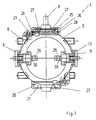
- a device according to the invention for adjusting the carbon brushes with an integrated changeover switch for such a reversible electric motor can be seen in more detail in FIG. 1 in a side view, the electric motor being shown only schematically.
- the device is designed as a flat component 1, which can be placed on the stator 4 of the electric motor in the axial direction 36.
- component 1 is used, for example, for fastening screwed, fixed with connector parts 13 or attached in a similar manner.
- the component 1 surrounds the collector 3 in a ring in the radial direction 37 on the rotor 2 of the electric motor.
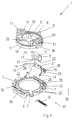
- the component 1 consists of a carrier 5 and a contact plate 6, as can be seen in particular in FIG. 4, in which the component 1 is shown in an exploded perspective view.
- the carrier 5 and the contact plate 6 can be assembled into component 1 by means of snap hooks 7 or other guide hooks projecting from the contact plate 6 in the axial direction 36.
- the snap hooks 7 can also be reversed on the carrier 5.
- the carrier 5 can be pivoted on the contact plate 6 by means of a handle 8, while the contact plate 6 is fixed in place on the stator 4 of the electric motor, as can be seen from FIG. 1.
- the carrier 5 and the contact plate 6 are made of plastic and are produced, for example, by injection molding.
- the chambers 10 each hold a brush holder 9, only one brush holder 9 being shown in FIG. 4.
- a molded hook on the chamber 10 engages by means of a pin 38 in a recess 12 on the brush holder 9 for fastening it in the chamber 10.
- the carbon brush 34 is in turn arranged, which rubs under spring pressure on the collector 3 of the electric motor when the component 1 is on Electric motor is mounted. Since the chamber 10 is open in the radial direction 37, there is thus the possibility of changing the brush holder 9 together with the carbon brush 34 in the installed state of the component 1 on the electric motor, without further disassembly of the component 1 being necessary.
- a pivoting of the carrier 5 by means of the handle 8 consequently leads to a pivoting of the carbon brushes 34 on the collector 3, as can be seen, for example, from FIG. 1.
- the contact system for this switch is located in component 1.
- the contact system consists of fixed contacts and switch contacts, the fixed contacts with the field windings on the stator 4 and the switch contacts with the carbon brushes 34 in the brush holder 9 being in electrical connection.
- the fixed contacts interact with the switching contacts as counter contacts in an alternate contacting of the carbon brushes 34 to reverse the direction of rotation of the electric motor when the carrier 5 is pivoted on the contact plate 6.
- the fixed contacts consist of two contact strips 19, only one of which is shown in FIG. 4.
- the contact strip 19 has, as contact surfaces 14 of the fixed contacts, end sections which are elastic in the radial direction 37, so that two contact surfaces 14 are located on each contact strip 19.
- In the contact plate 6 there is a groove 20 on the side facing the carrier 5, in which the two contact strips 19 are arranged opposite one another.
- On each contact strip 19, a line web 21 extends approximately centrally between the two contact surfaces 14.
- the land bridge 21 serves for the electrical connection of the contact strip 19 to the respective connection 16 for the field winding on the stator 4 of the electric motor.
- the contact strip 19, the line bridge 21 and the connection 16 for the field winding can be designed as a one-piece, metallic stamped part.
- the brush holder 9 located in the chamber 10 is arranged on the carrier 5 such that a surface 17 of the brush holder 9 faces the contact plate 6. A part 15 protrudes from this surface 17.
- This protruding part 15 projects into the area of the fixed contacts located in the groove 20 of the contact plate 6 and serves as a switching contact for direct contacting with the contact surfaces 14 on the contact strips 19.
- the protruding part 15 located on the brush holder 9 is preferably approximately perpendicular to the surface 17 and thus extends essentially in the axial direction 36.
- the contact strips 19 are in turn arranged approximately parallel to the protruding part 15 and thus also essentially in the axial direction 36 in the groove 20, the contact surfaces 14 on the contact strip 19 having an elasticity approximately in the radial direction Own direction 37.
- the switch contacts thus interact with the fixed contacts essentially in the radial direction 37 for making contact. This advantageously gives reliable contact, even with vibrations and Like., Which can occur in particular when used in power tools.
- the chamber 10 is particularly preferably designed to be open in the axial direction 36 on the side facing the contact plate 6.
- the surface 17 then represents a free surface 17 with respect to the carrier 5, which faces the contact plate 6.
- the brush holder 9 is made of metal, for example copper, so that the free surface 17 consists of electrically conductive material.
- the part 15 can, for example, be cut free from the free surface 17 and bent in one piece from the free surface 17, as can be seen in particular from FIG. 5.
- the electrical connection between the projecting part 15, which acts as a switching contact, and the carbon brush 34 is established via the surface 17.
- the switching positions of the component 1 used to switch the direction of rotation of the electric motor which can be adjusted when the support 5 is pivoted on the contact plate 6 by the interaction of the protruding parts 15 on the two brush holders 9 as switching contacts and the respective contact surfaces 14 of the two contact strips 19 as fixed contacts are shown in more detail in FIG. 6.
- the pair of brush holders 9 with the reference numerals 9a, 9b, the protruding parts 15 with the reference numerals 15a, 15b and the contact strips 19 with the reference numerals 19a, 19b are designated in more detail.
- the paired contact surfaces 14 are designated in greater detail on the contact strip 19a with the reference symbols 14a, 14c and on the contact strip 19b with 14b, 14d.
- the brush holder 9a contacts the contact surface 14b on the contact strip 19b by means of the part 15a and the brush holder 9b contacts the contact surface 14c on the contact strip 19a by means of the part 15b.
- the handle 8 in FIG. 6 is pivoted to the right according to the arrow 41, so that the brush holder 9a contacts the contact surface 14a on the contact strip 19a and the brush holder 9b contacts the contact surface 14d on the contact strip 19b.
- the contact strips 19a, 19b are thus alternately contacted by the brush holders 9a, 9b in the two switching positions, so that the polarity of the brush holders 9a, 9b is reversed in relation to the connections 16.
- the latching positions are determined in the present case by the interaction of a latching curve 22, which is located in the contact plate 6, with a latching spring 23, which is connected to the carrier 5.
- the detent spring 23 is preferably an axially Elastic element in the direction 36 on the surface 17 of the brush holder 9.
- the locking spring 23 can expediently be formed in one piece with the surface 17, as can be seen in particular in FIG. 5.
- the contact system consisting of the contact surfaces 14 and the protruding parts 15 is largely encapsulated by the component 1.
- a shoulder-shaped edge 18 on the carrier 5 covers the contact system upwards in the view according to FIG. 4.
- the contact system located in the groove 20 is further covered by the contact plate 6 downwards and laterally. This provides good protection against the effects of dust or the like in the electric hand tool.
- connection 16 for the field winding of the stator 4 is advantageously arranged in a receptacle 35 on the contact plate 6.
- the receptacle 35 can be designed such that the connection 16 is exposed on the side of the contact plate 6 facing away from the carrier 5.
- the connections 16 and the counter connections on the field windings can be designed in the most varied of forms, for example as plug connections, wire connections, sleeve connections or the like. Due to the simplification of the assembly, it is particularly preferred to design the connections 16 in the manner of plug-in cutting terminals 24.
- the line web 21 can also be designed such that it is possible to make contact with a radio interference suppression choke 25 for the electric motor, as is shown schematically in the illustration in FIG. 3.
- a receptacle 26 is arranged for the radio interference suppression choke 25 on the side of the contact plate 6 facing away from the carrier 5. With this receptacle 26 a clasp 27 located on the contact plate 6 interacts to hold the radio interference suppressor 25. This enables a holder that is independent of the diameter of the radio interference suppression choke 25.
- clamp contacts 28 which are in electrical connection with the connections 16 via the line web 21 for plugging in the radio interference suppressor 25.
- component 1 can optionally be equipped with or without radio interference suppression choke 25. If the radio interference suppression choke 25 is inserted, the bridging connection on the line web 21 is broken, since the electrical connection to the connections 16 is then established via the radio interference suppression choke 25.
- component 1 is manufactured separately and is only attached to the electric motor by the manufacturer of the power tool.
- a holding element that can be removed subsequently is arranged in the region of the chambers 10. At the same time this holding element serves as an aid for the assembly of the Component 1 on the electric motor, since the carbon brushes 34 cannot collide with parts of the electric motor when the component 1 is placed on it.
- the holding element consists of webs 31 arranged in a star shape, which are molded onto the carrier 5. Between the webs 31, holding surfaces 32 are fastened in the region of the brush holder 9 located in the chambers 10, so that the carbon brushes 34 are retained in the brush holder 9. After assembly of the component 1 on the electric motor, the webs 31 are broken off and removed from the carrier 5 at the injection points 33, so that the carbon brushes 34 contact the collector 3 of the electric motor due to the spring pressure of the compression spring 39 acting on them.
- the webs 31 can be broken off together with the carbon brushes 34 into the chambers 10 at the injection points 33 already after the brush holders 9 have been inserted, since in this case the webs 31 still bear against the carrier 5 for securing transport. Then the webs 31 with the holding surfaces 32 are automatically pushed out of the carrier 5 during the assembly of the component 1 on the electric motor.
- the holding element consists of individual holding tabs 29 located on the chamber 10, which retain the carbon brush 34 in the brush holder 9 by means of a pin 30. After assembly, the retaining tabs 29 are broken off, so that the carbon brushes 34 under the Action of a compression spring 39 or the like. Step out of the brush holder 9 and lie on the collector 3 of the electric motor.
- the invention is not restricted to the exemplary embodiments described and illustrated. Rather, it also includes all professional training within the scope of the inventive concept.
- the device according to the invention for adjusting the carbon brushes can be used not only in power tools but also in other devices with electric motors, for example in kitchen work tools or the like.
Abstract
Description
Die Erfindung betrifft eine Vorrichtung zur Verstellung der Kohlebürsten für einen reversiblen Elektromotor nach dem Oberbegriff des Patentanspruchs 1.The invention relates to a device for adjusting the carbon brushes for a reversible electric motor according to the preamble of
Elektrohandwerkzeuge, wie Bohrmaschinen, Schrauber o. dgl., sind häufig für einen Betrieb sowohl im Rechts- als auch im Linkslauf ausgestaltet, wobei am Elektrowerkzeug ein elektrischer Umschalter für die Polarität der Anschlüsse des Elektromotors angeordnet ist. Zur Verbesserung des Wirkungsgrads des Elektromotors in beiden Drehrichtungen kann bei der Umschaltung der Drehrichtung zusätzlich eine Verstellung der Kohlebürsten in die jeweils optimale Stellung vorgenommen werden.Electric hand tools, such as drills, screwdrivers or the like, are often designed for operation in both clockwise and counter-clockwise rotation, with an electrical switch for the polarity of the connections of the electric motor being arranged on the power tool. To improve the efficiency of the electric motor in both directions of rotation, the carbon brushes can also be adjusted to the optimum position when the direction of rotation is switched.
Aus der EP-B-0 208 137 ist ein Elektrohandwerkzeug mit einem reversiblen Elektromotor bekannt, an dem eine Vorrichtung zur Verstellung der Kohlebürsten unter gleichzeitiger Umschaltung der Drehrichtung des Elektromotors angeordnet ist. Diese Vorrichtung besteht aus einer ortsfesten, am Stator des Elektromotors angesteckten Kontaktplatte und einem Träger, der seinerseits an der Kontaktplatte verschwenkbar ist. Am Träger sind die Bürstenhalter für die auf dem Kollektor des Elektromotors schleifenden Kohlebürsten befestigt. Der Träger ist mit einem Hohlraum ausgestaltet, in der mit den Kohlebürsten in elektrischer Verbindung stehende Schaltkontakte angeordnet sind. Die Kontaktplatte dient zur Aufnahme von Festkontakten, die wiederum mit den Anschlüssen für die Feldwicklungen des Elektromotors in Verbindung stehen. Die Festkontakte besitzen Kontaktflächen, die mit den Schaltkontakten als Gegenkontakte in einer wechselweisen Kontaktierung der Kohlebürsten bei Verschwenkung des Trägers zusammenwirken, womit eine Drehrichtungsumkehr des Elektromotors erfolgt.From EP-B-0 208 137 an electric hand tool with a reversible electric motor is known, on which a device for adjusting the carbon brushes while switching over the Direction of rotation of the electric motor is arranged. This device consists of a fixed contact plate attached to the stator of the electric motor and a carrier which in turn can be pivoted on the contact plate. The brush holders for the carbon brushes grinding on the collector of the electric motor are attached to the carrier. The carrier is designed with a cavity in which switching contacts which are in electrical connection with the carbon brushes are arranged. The contact plate serves to accommodate fixed contacts, which in turn are connected to the connections for the field windings of the electric motor. The fixed contacts have contact surfaces which interact with the switching contacts as counter-contacts in an alternating contacting of the carbon brushes when the carrier is pivoted, which reverses the direction of rotation of the electric motor.
Nachteilig bei der bekannten Vorrichtung zur Verstellung der Kohlebürsten und zur Umschaltung der Drehrichtung des Elektromotors ist, daß die Schalt- und Festkontakte aufwendig ausgestaltet sind. Weiter ist ein zusätzlicher Aufwand darin zu sehen, daß eine separate elektrische Verbindung zwischen den Kohlebürsten und den Schaltkontakten notwendig ist. Dies verteuert die Fertigung der Vorrichtung und kompliziert deren Montage. Außerdem ist aufgrund der zusätzlichen elektrischen Verbindungen und der komplexen Anordnung der Kontakte die Gefahr groß, daß Fehlschaltungen und Schaltungsausfälle auftreten. Damit ist die bekannte Vorrichtung nicht funktionssicher.A disadvantage of the known device for adjusting the carbon brushes and for switching the direction of rotation of the electric motor is that the switching and fixed contacts are complex. Furthermore, an additional effort is to be seen in the fact that a separate electrical connection between the carbon brushes and the switch contacts is necessary. This makes the device more expensive to manufacture and complicates its assembly. In addition, due to the additional electrical connections and the complex arrangement of the contacts, there is a high risk that incorrect switching and circuit failures occur. The known device is therefore not functionally reliable.
Die bekannte Vorrichtung ist nicht komplett vormontierbar. So können die Kohlebürsten erst bei der Montage am Elektromotor eingesetzt werden. Dabei gestaltet sich die Montage aufgrund mehrerer gleichzeitig zu montierender Einzelteile aufwendig. Ein nachträgliches Auswechseln der Kohlebürsten, die ein Verschleißteil am Elektromotor darstellen, ist nur durch Demontage und Zerlegen der Vorrichtung möglich. Folglich mangelt es dieser Vorrichtung auch an Servicefreundlichkeit.The known device cannot be completely preassembled. So the carbon brushes can only be used during assembly on the electric motor. The assembly is complex due to several individual parts to be assembled simultaneously. Subsequent replacement of the carbon brushes, which are wearing parts on the electric motor, is only possible by disassembling and disassembling the device. As a result, this device also lacks serviceability.
Der Erfindung liegt die Aufgabe zugrunde, eine Vorrichtung zur Verstellung der Kohlebürsten und zur Umschaltung der Drehrichtung eines Elektromotors derart auszugestalten, daß die Kontakt- und Funktionssicherheit verbessert ist. Zudem soll eine vereinfachte Montage der Vorrichtung am Elektromotor gewährleistet sein.The invention is based on the object of designing a device for adjusting the carbon brushes and for switching the direction of rotation of an electric motor in such a way that the contact and functional reliability is improved. In addition, a simplified assembly of the device on the electric motor should be ensured.
Diese Aufgabe wird bei einer gattungsgemäßen Vorrichtung durch die kennzeichnenden Merkmale des Anspruchs 1 gelöst.This object is achieved in a generic device by the characterizing features of
Weitere Ausgestaltungen der Erfindung sind Gegenstand der Unteransprüche.Further embodiments of the invention are the subject of the dependent claims.
Die Vorrichtung ist als kompaktes Bauteil ausgestaltbar, wobei das Bauteil aus einem Träger und einer Kontaktplatte besteht, die mittels Schnapp- und/oder Führungshaken zusammensetzbar sind. Dadurch ist das Kontaktsystem für den Umschalter durch das Bauteil gekapselt, so daß ein besonders guter Staubschutz, wie er insbesondere beim Einsatz in Elektrohandwerkzeugen erforderlich ist, erzielbar ist.The device can be configured as a compact component, the component consisting of a carrier and a contact plate which can be assembled by means of snap and / or guide hooks. As a result, the contact system for the changeover switch is encapsulated by the component, so that particularly good dust protection, as is required in particular when used in electric hand tools, can be achieved.
In einer weiteren Ausführung sind die Kontaktflächen der Festkontakte als elastisch absgebildete Endabschnitte von Kontaktbändern ausgebildet. In der Vorrichtung befinden sich zwei Kontaktbänder mit je zwei Kontaktflächen, wobei ein Leitungssteg zur elektrischen Verbindung des Kontaktbandes zum jeweiligen Anschluß für die Feldwicklungen ungefähr mittig zwischen den Kontaktflächen vom Kontaktband abgeht. Es bietet sich an, das Kontaktband, den Leitungssteg und den Anschluß für die Feldwicklung als einstückiges Stanzteil auszubilden. Die Kontaktbänder können sich in einer Nut in der Kontaktplatte, die an der dem Träger zugewandten Seite angeordnet ist, befinden.In a further embodiment, the contact surfaces of the fixed contacts are designed as elastically reproduced end sections of contact strips. There are two contact strips in the device, each with two contact surfaces, with a line web for the electrical connection of the contact strip to the respective connection for the field windings extending approximately centrally between the contact surfaces from the contact strip. It is advisable to design the contact strip, the line bridge and the connection for the field winding as a one-piece stamped part. The contact strips can be located in a groove in the contact plate, which is arranged on the side facing the carrier.
In Weiterbildung der Erfindung ist der als Schaltkontakt wirkende Teil der der Kontaktplatte zugewandten, freien Fläche des Bürstenhalters von der freien Fläche abstehend ausgebildet, wobei dieser einstückig von der freien Fläche abgebogen sein kann. Dabei steht der Schaltkontakt ungefähr senkrecht zur freien Fläche und verläuft in Bezug auf den Elektromotor in achsialer Richtung. Die Festkontakte sind ungefähr parallel zum Schaltkontakt, in achsialer Richtung in der Nut verlaufend angeordnet, wobei die Kontaktflächen eine Elastizität in radialer Richtung besitzen. Dadurch wirken die Schaltkontakte mit den Kontaktflächen der Festkontakte in radialer Richtung zur Kontaktgabe zusammen.In a further development of the invention, the part of the free surface of the brush holder facing the contact plate, which acts as a switching contact, is formed so as to protrude from the free surface, and it can be bent in one piece from the free surface. The switch contact is approximately perpendicular to the free surface and runs in the axial direction with respect to the electric motor. The fixed contacts are arranged approximately parallel to the switching contact, running in the axial direction in the groove, the contact surfaces having an elasticity in the radial direction. As a result, the switching contacts interact with the contact surfaces of the fixed contacts in the radial direction for making contact.
Es bietet sich an, die bei Verschwenkung des Trägers durch das Zusammenwirken der Schaltkontakte und der Festkontakte einstellbaren Schaltstellungen als Raststellungen auszubilden. Dazu befindet sich in der Kontaktplatte eine Rastkurve und an dem Bürstenhalter eine Rastfeder, die in achsialer Richtung elastisch ist. Die Rastfeder kann einstückig mit der freien Fläche des Bürstenhalters, beispielsweise als Stanzbiegeteil, ausgebildet sein.It is advisable to design the switch positions that can be set when the carrier is pivoted by the interaction of the switch contacts and the fixed contacts as detent positions. For this purpose there is a locking curve in the contact plate and a locking spring on the brush holder, which is elastic in the axial direction. The detent spring can be formed in one piece with the free surface of the brush holder, for example as a stamped and bent part.
Um eine einfache Möglichkeit zum Wechseln der Kohlebürsten zu gewährleisten, kann am Träger eine in radialer Richtung beidseitig offene Kammer zur Aufnahme der Bürstenhalter angeformt sein. Zur Befestigung der Bürstenhalter in der Kammer dient ein an der Kammer angeformter Haltehaken, der wiederum in der Art eines Schnappelementes in eine Ausnehmung am Bürstenhalter eingreift.In order to ensure a simple possibility of changing the carbon brushes, a chamber open on both sides in the radial direction for receiving the brush holders can be integrally formed on the carrier. To hold the brush holder in the chamber, a retaining hook is formed on the chamber, which in turn engages in the manner of a snap element in a recess on the brush holder.
Mittels an dem Träger angeordneter Halteelemente können die Kohlebürsten zur Transportsicherung im Bürstenhalter zurückgehalten sein. Gleichzeitig dienen diese Halteelemente als Hilfe für die Montage der Vorrichtung am Elektromotor, da dann deren Aufstecken am Elektromotor möglich ist, ohne daß die Kohlebürsten stören. Nach der Montage der Vorrichtung ist das Halteelement entfernbar, beispielsweise indem es abgebrochen wird.By means of holding elements arranged on the carrier, the carbon brushes can be retained in the brush holder for securing transportation. At the same time, these holding elements serve as an aid for mounting the device on the electric motor, since it is then possible to plug it onto the electric motor without the carbon brushes interfering. After the device has been installed, the holding element can be removed, for example by being broken off.
Es ist weiter vorteilhaft, wenn die Anschlüsse für die Feldwicklungen an der dem Träger abgewandten Seite der Kontaktplatte frei liegen, so daß beim Aufsetzen der Vorrichtung auf den Stator des Elektromotors die elektrische Verbindung zwischen den Anschlüssen und den Feldwicklungen herstellbar ist. Die Anschlüsse können auf unterschiedlichste Art, beispielsweise als Steckschneid-Klemme, Stecker, Drahtanschluß, Hülsenanschluß o. dgl. ausgebildet sein.It is further advantageous if the connections for the field windings are exposed on the side of the contact plate facing away from the carrier, so that the electrical connection between the connections and the field windings can be established when the device is placed on the stator of the electric motor. The connections can be designed in a wide variety of ways, for example as a plug-in terminal, plug, wire connection, sleeve connection or the like.
In noch weiterer Ausbildung ist an der dem Träger abgewandten Seite der Kontaktplatte eine Aufnahme für eine Funkentstördrossel angeordnet. Mittels einer Spange können in der Aufnahme Funkentstördrosseln mit verschiedenen Durchmessern gehalten werden. Die Funkentstördrosseln werden in Klemmkontakte eingesteckt, die wiederum mit den Anschlüssen in elektrischer Verbindung stehen. Um die Vorrichtung wahlweise mit oder ohne Funkentstördrossel herstellen zu können, ist die die Klemmkontakte überbrückende elektrische Verbindung durch ein Schneidwerkzeug o. dgl. nachträglich auftrennbar.In yet another embodiment, a receptacle for a radio interference suppression choke is arranged on the side of the contact plate facing away from the carrier. Radio interference suppression chokes with different diameters can be held in the receptacle by means of a clip. The radio interference suppression chokes are plugged into terminal contacts, which in turn are in electrical connection with the connections. In order to be able to produce the device either with or without radio interference suppression choke, the electrical connection bridging the clamping contacts can subsequently be separated by a cutting tool or the like.
Die mit der Erfindung erzielten Vorteile bestehen insbesondere darin, daß das Kontaktsystem für den Umschalter einfach aufgebaut und damit kostengünstig herzustellen ist. Weiter ist die Kontaktsicherheit verbessert, so daß die Gefahr von Ausfällen vermindert und die Funktionssicherheit der Vorrichtung erhöht ist.The advantages achieved by the invention are, in particular, that the contact system for the changeover switch is simple in construction and therefore inexpensive to manufacture. Furthermore, the contact reliability is improved, so that the risk of failures is reduced and the functional reliability of the device is increased.
Bei der Vorrichtung nach der Erfindung handelt es sich um ein kompaktes Bauteil, das komplett vormontierbar ist. Das Bauteil läßt sich sicher transportieren, insbesondere ist eine Beschädigung durch Herausspringen der Kohlenbürsten während des Transports wirksam verhindert. Weiter läßt sich das Bauteil durch einfaches Aufstecken leicht am Elektromotor montieren, wodurch eine Ersparnis bei den Montagekosten resultiert. Zudem ist für Servicefälle auch ein Auswechseln der Kohlebürsten auf einfache Weise und ohne Demontage des Elektrogeräts möglich.The device according to the invention is a compact component that can be completely preassembled. The component can be transported safely, in particular damage caused by the carbon brushes jumping out during transport is effectively prevented. Furthermore, the component can be easily mounted on the electric motor by simply plugging it on, which results in savings in assembly costs. In addition, the carbon brushes can be replaced easily and without disassembling the electrical device for service purposes.
Ausführungsbeispiele der Erfindung sind in den Zeichnungen dargestellt und werden im folgenden näher beschrieben. Es zeigen
- Fig. 1
- eine an einem Elektromotor angeordnete Vorrichtung zur Verstellung der Kohlebürsten in Seitenansicht,
- Fig. 2
- die Draufsicht in Richtung gemäß dem
Pfeil 36 auf die in Fig. 1 gezeigte Vorrichtung ohne Elektromotor, - Fig. 3
- die Draufsicht in Gegenrichtung zum Pfeil 36 aus Fig. 1 auf eine Vorrichtung in weiterer Ausführungsform, wobei der Elektromotor wiederum weggelassen ist,
- Fig. 4
- die Vorrichtung zur Verstellung der Kohlebürsten in Explosiv-Darstellung,
- Fig. 5
- die Seitenansicht eines Bürstenhalters für die Kohlebürste und
- Fig. 6
- eine Darstellung wie in Fig. 2 gemäß der weiteren Ausführungsform, jedoch derart aufgebrochen, daß das Kontaktsystem sichtbar ist.
- Fig. 1
- a device arranged on an electric motor for adjusting the carbon brushes in side view,
- Fig. 2
- the top view in the direction according to
arrow 36 on the device shown in Fig. 1 without an electric motor, - Fig. 3
- the plan view in the opposite direction to the
arrow 36 from FIG. 1 of a device in a further embodiment, the electric motor again being omitted, - Fig. 4
- the device for adjusting the carbon brushes in Exploded view,
- Fig. 5
- the side view of a brush holder for the carbon brush and
- Fig. 6
- a representation as in Fig. 2 according to the further embodiment, but broken away such that the contact system is visible.
Elektrohandwerkzeuge für den Netzbetrieb, wie Bohrmaschinen, Schraubmaschinen o. dgl., besitzen in der Regel einen Universalmotor als Elektromotor, der oft für einen Betrieb sowohl im Rechts- als auch im Linkslauf ausgestaltet ist. Zur Umschaltung zwischen Rechts- und Linkslauf ist die Polarität der Anschlüsse für den Elektromotor zu vertauschen. Es kann bei einer derartigen Umschaltung gleichzeitig eine Verstellung der Kohlebürsten des Elektromotors vorgenommen werden, um die Kohlebürsten in eine optimale Stellung am Kollektor in Bezug auf die jeweilige Laufrichtung auszurichten. Eine erfindungsgemäße Vorrichtung zur Verstellung der Kohlebürsten mit integriertem Umschalter für einen derartigen reversiblen Elektromotor ist in Fig. 1 in Seitenansicht näher zu sehen, wobei der Elektromotor lediglich schematisch dargestellt ist.Electric hand tools for network operation, such as drilling machines, screwing machines or the like, generally have a universal motor as an electric motor, which is often designed for operation in both clockwise and counterclockwise rotation. To switch between clockwise and counterclockwise rotation, the polarity of the connections for the electric motor must be reversed. With such a changeover, the carbon brushes of the electric motor can be adjusted at the same time in order to align the carbon brushes in an optimal position on the collector with respect to the respective running direction. A device according to the invention for adjusting the carbon brushes with an integrated changeover switch for such a reversible electric motor can be seen in more detail in FIG. 1 in a side view, the electric motor being shown only schematically.
Die Vorrichtung ist als flaches Bauteil 1 ausgebildet, das auf den Stator 4 des Elektromotors in achsialer Richtung 36 aufsetzbar ist. Am Stator 4 wird das Bauteil 1 beispielsweise zur Befestigung angeschraubt, mit Steckverbindungsteilen 13 fixiert oder in ähnlicher Weise befestigt. Das Bauteil 1 umgibt den Kollektor 3 am Rotor 2 des Elektromotors ringförmig in radialer Richtung 37.The device is designed as a
Das Bauteil 1 besteht aus einem Träger 5 und einer Kontaktplatte 6, wie man insbesondere der Fig. 4 entnehmen kann, in der das Bauteil 1 in explosionsartiger Perspektivdarstellung gezeigt ist. Der Träger 5 und die Kontaktplatte 6 sind mittels in achsialer Richtung 36 von der Kontaktplatte 6 abstehender Schnapphaken 7 oder sonstiger Führungshaken zum Bauteil 1 zusammensetzbar. Selbstverständlich können die Schnapphaken 7 auch umgekehrt am Träger 5 angebracht sein. Mittels eines Griffs 8 ist der Träger 5 auf der Kontaktplatte 6 verschwenkbar, während die Kontaktplatte 6 ortsfest am Stator 4 des Elektromotors befestigt ist, wie man anhand der Fig. 1 erkennt.The
Der Träger 5 und die Kontaktplatte 6 bestehen aus Kunststoff und sind beispielsweise im Spritzgießverfahren hergestellt. Wie weiter aus Fig. 4 hervorgeht, sind am Träger 5 zwei einander diametral gegenüberstehende, in radialer Richtung 37 beidseitig offene Kammern 10 angeformt. Die Kammern 10 dienen zur Aufnahme jeweils eines Bürstenhalters 9, wobei in Fig. 4 nur ein Bürstenhalter 9 gezeigt ist. Dabei greift ein an der Kammer 10 angeformter Haltehaken 11 mittels eines Zapfens 38 in eine Ausnehmung 12 am Bürstenhalter 9 zu dessen Befestigung in der Kammer 10 ein. Im Bürstenhalter 9 ist wiederum die Kohlebürste 34 angeordnet, die unter Federdruck auf dem Kollektor 3 des Elektromotors schleift, wenn das Bauteil 1 am Elektromotor montiert ist. Da die Kammer 10 in radialer Richtung 37 offen ist, besteht somit die Möglichkeit, den Bürstenhalter 9 mitsamt der Kohlebürste 34 in eingebautem Zustand des Bauteils 1 am Elektromotor zu wechseln, ohne daß eine weitergehende Zerlegung des Bauteils 1 notwendig wäre.The
Eine Verschwenkung des Trägers 5 mittels des Griffs 8 führt folglich zu einer Verschwenkung der Kohlebürsten 34 am Kollektor 3, wie man beispielsweise anhand der Fig. 1 erkennt. Gleichzeitig erfolgt bei der Verschwenkung des Trägers 5 eine Umschaltung zwischen den beiden Drehrichtungen des Elektromotors. Dazu befindet sich im Bauteil 1 weiter das Kontaktsystem für diesen Umschalter. Das Kontaktsystem besteht aus Festkontakten und Schaltkontakten, wobei die Festkontakte mit den Feldwicklungen am Stator 4 und die Schaltkontakte mit den Kohlebürsten 34 im Bürstenhalter 9 in elektrischer Verbindung stehen. Die Festkontakte wirken mit den Schaltkontakten als Gegenkontakte in einer wechselweisen Kontaktierung der Kohlebürsten 34 zur Drehrichtungsumkehr des Elektromotors bei Verschwenkung des Trägers 5 auf der Kontaktplatte 6 zusammen. Die Ausbildung des Kontaktsystems soll im folgenden näher erläutert werden.A pivoting of the
Die Festkontakte bestehen aus zwei Kontaktbändern 19, von denen in Fig. 4 nur eines gezeigt ist. Das Kontaktband 19 besitzt als Kontaktflächen 14 der Festkontakte dienende, in radialer Richtung 37 elastisch ausgebildete Endabschnitte, so daß an jedem Kontaktband 19 jeweils zwei Kontaktflächen 14 befindlich sind. In der Kontaktplatte 6 befindet sich an der dem Träger 5 zugewandten Seite eine Nut 20, in der die zwei Kontaktbänder 19 einander gegenüberliegend angeordnet sind. An jedem Kontaktband 19 geht ungefähr mittig zwischen den beiden Kontaktflächen 14 ein Leitungssteg 21 ab. Der Leitungssteg 21 dient zur elektrischen Verbindung des Kontaktbandes 19 mit dem jeweiligen Anschluß 16 für die Feldwicklung am Stator 4 des Elektromotors. Vorteilhafterweise kann das Kontaktband 19, der Leitungssteg 21 und der Anschluß 16 für die Feldwicklung als einstückiges, metallisches Stanzteil ausgebildet sein.The fixed contacts consist of two
Der in der Kammer 10 befindliche Bürstenhalter 9 ist derart am Träger 5 angeordnet, daß eine Fläche 17 des Bürstenhalters 9 der Kontaktplatte 6 zugewandt ist. Ein Teil 15 steht von dieser Fläche 17 ab. Dieser abstehende Teil 15 ragt in den Bereich der in der Nut 20 der Kontaktplatte 6 befindlichen Festkontakte hinein und dient als Schaltkontakt zur direkten Kontaktierung mit den Kontaktflächen 14 an den Kontaktbändern 19. Der am Bürstenhalter 9 befindliche abstehende Teil 15 steht vorzugsweise ungefähr senkrecht zur Fläche 17 und verläuft somit im wesentlichen in achsialer Richtung 36. Die Kontaktbänder 19 sind wiederum ungefähr parallel zum abstehenden Teil 15 und damit ebenfalls im wesentlichen in achsialer Richtung 36 in der Nut 20 verlaufend angeordnet, wobei die Kontaktflächen 14 an dem Kontaktband 19 eine Elastizität ungefähr in radialer Richtung 37 besitzen. Damit wirken die Schaltkontakte mit den Festkontakten im wesentlichen in radialer Richtung 37 zur Kontaktgabe zusammen. Dadurch erhält man vorteilhafterweise eine zuverlässige Kontaktgabe, selbst bei Erschütterungen u. dgl., die insbesondere beim Einsatz in Elektrowerkzeugen auftreten können.The
Besonders bevorzugterweise ist die Kammer 10 in achsialer Richtung 36, an der der Kontaktplatte 6 zugewandten Seite ebenfalls offen ausgebildet. Die Fläche 17 stellt dann im Hinblick auf den Träger 5 eine freie Fläche 17 dar, die der Kontaktplatte 6 zugewandt ist. Der Bürstenhalter 9 ist aus Metall hergestellt, beispielsweise aus Kupfer, so daß die freie Fläche 17 aus elektrisch leitfähigem Material besteht. Der Teil 15 kann beispielsweise aus der freien Fläche 17 freigeschnitten und einstückig von der freien Fläche 17 abgebogen sein, wie insbesondere aus der Fig. 5 entnommen werden kann. Wie weiter aus der Fig. 5 hervorgeht, wird die elektrische Verbindung zwischen dem als Schaltkontakt wirkenden abstehenden Teil 15 und der Kohlebürste 34 über die Fläche 17 hergestellt. Zur Erzeugung der Kraft in radialer Richtung 37, mit der sich die Kohlebürste 34 am Kollektor 3 des Elektromotors anlegt, befindet sich im Bürstenhalter 9 eine auf die Kohlebürste 34 einwirkende Druckfeder 39, die sich an der Rückwand 40 des Bürstenhalters 9 abstützt.The
Die zum Umschalten der Drehrichtung des Elektromotors dienenden Schaltstellungen des Bauteils 1, die bei Verschwenkung des Trägers 5 auf der Kontaktplatte 6 durch das Zusammenwirken der abstehenden Teile 15 an den beiden Bürstenhaltern 9 als Schaltkontakte und der jeweiligen Kontaktflächen 14 der beiden Kontaktbänder 19 als Festkontakte einstellbar sind, gehen näher aus Fig. 6 hervor. Dort sind zur besseren Verdeutlichung die jeweils paarweise vorhandenen Bürstenhalter 9 mit den Bezugszeichen 9a, 9b, die abstehenden Teile 15 mit den Bezugszeichen 15a, 15b und die Kontaktbänder 19 mit den Bezugszeichen 19a, 19b näher bezeichnet. Die paarweisen Kontaktflächen 14 sind am Kontaktband 19a mit den Bezugszeichen 14a, 14c und am Kontaktband 19b mit 14b, 14d näher bezeichnet. In Fig. 6 ist eine erste Schaltstellung gezeigt, die beispielsweise dem Rechtslauf des Elektromotors entspricht. In der ersten Schaltstellung kontaktiert der Bürstenhalter 9a mittels des Teils 15a die Kontaktfläche 14b am Kontaktband 19b und der Bürstenhalter 9b mittels des Teils 15b die Kontaktfläche 14c am Kontaktband 19a. Zum Einschalten der zweiten Schaltstellung wird der Griff 8 in Fig. 6 gemäß dem Pfeil 41 nach rechts verschwenkt, so daß der Bürstenhalter 9a die Kontaktfläche 14a am Kontaktband 19a und der Bürstenhalter 9b die Kontaktfläche 14d am Kontaktband 19b kontaktieren. Wie man sieht, findet in den beiden Schaltstellungen somit eine wechselweise Kontaktierung der Kontaktbänder 19a, 19b durch die Bürstenhalter 9a, 9b statt, womit die Polarität der Bürstenhalter 9a, 9b gegenüber den Anschlüssen 16 jeweils vertauscht wird.The switching positions of the
Es ist nun weiter zweckmäßig, diese beiden Schaltstellungen als Raststellungen auszubilden. Wie in Fig. 4 gezeigt ist, sind die Raststellungen vorliegend durch das Zusammenwirken einer Rastkurve 22, die sich in der Kontaktplatte 6 befindet, mit einer Rastfeder 23, die mit dem Träger 5 in Verbindung steht, festgelegt. Bei der Rastfeder 23 handelt es sich vorzugsweise um ein in achsialer Richtung 36 elastisches Element an der Fläche 17 der Bürstenhalterung 9. Zweckmäßigerweise kann die Rastfeder 23 einstückig mit der Fläche 17 ausgebildet sein, wie insbesondere der Fig. 5 zu entnehmen ist.It is now further expedient to design these two switching positions as locking positions. As shown in FIG. 4, the latching positions are determined in the present case by the interaction of a
Wie man anhand der Fig. 4 sieht, ist das aus den Kontaktflächen 14 und den abstehenden Teilen 15 bestehende Kontaktsystem durch das Bauteil 1 weitgehend gekapselt. Dabei deckt insbesondere ein absatzförmiger Rand 18 am Träger 5 das Kontaktsystem in der Ansicht gemäß Fig. 4 nach oben ab. Das in der Nut 20 befindliche Kontaktsystem ist weiter durch die Kontaktplatte 6 nach unten sowie seitlich abgedeckt. Somit ist ein guter Schutz vor Staubeinflüssen o. dgl. im Elektrohandwerkzeug gegeben.As can be seen from FIG. 4, the contact system consisting of the contact surfaces 14 and the protruding
Vorteilhafterweise ist der Anschluß 16 für die Feldwicklung des Stators 4 in einer Aufnahme 35 an der Kontaktplatte 6 angeordnet. Dabei kann die Aufnahme 35 derart ausgebildet sein, daß der Anschluß 16 an der dem Träger 5 abgewandten Seite der Kontaktplatte 6 frei liegt. Dadurch ist beim Aufsetzen des Bauteils 1 auf den Stator 4 des Elektromotors gleichzeitig die elektrische Verbindung zwischen den Anschlüssen 16 und den Feldwicklungen herstellbar. Die Anschlüsse 16 sowie die Gegenanschlüsse an den Feldwicklungen können hierzu in verschiedenster Form, beispielsweise als Steckanschlüsse, Drahtanschlüsse, Hülsenanschlüsse o. dgl. ausgebildet sein. Besonders bevorzugt aufgrund der Vereinfachung der Montage ist, die Anschlüsse 16 in der Art von Steckschneid-Klemmen 24 auszubilden.The
Der Leitungssteg 21 kann weiter derart ausgebildet sein, daß eine Kontaktgabe zu einer Funkentstördrossel 25 für den Elektromotor, wie sie in der Darstellung der Fig. 3 schematisch gezeigt ist, ermöglicht ist. Für die Funkentstördrossel 25 ist an der dem Träger 5 abgewandten Seite der Kontaktplatte 6 eine Aufnahme 26 angeordnet. Mit dieser Aufnahme 26 wirkt eine an der Kontaktplatte 6 befindliche Spange 27 zur Halterung der Funkentstördrossel 25 zusammen. Dadurch ist eine vom Durchmesser der Funkentstördrossel 25 unabhängige Halterung ermöglicht. In der Aufnahme 26 befinden sich mit den Anschlüssen 16 über den Leitungssteg 21 in elektrischer Verbindung stehende Klemmkontakte 28 zum Aufstecken der Funkentstördrossel 25. Die elektrische Überbrückung durch den Leitungssteg 21 zwischen den beiden Klemmkontakten 28 ist nachträglich mittels eines Schneidwerkzeugs, beispielsweise eines Schneidmessers, auftrennbar. Dadurch ist das Bauteil 1 wahlweise mit oder ohne Funkentstördrossel 25 ausrüstbar. Ist die Funkentstördrossel 25 eingesetzt, so wird die überbrückende Verbindung am Leitungssteg 21 aufgetrennt, da dann über die Funkentstördrossel 25 die elektrische Verbindung zu den Anschlüssen 16 hergestellt ist.The
Im allgemeinen wird das Bauteil 1 separat hergestellt und erst beim Hersteller des Elektrowerkzeugs am Elektromotor angebracht. Zur Transportsicherung für die Kohlebürsten 34 ist im Bereich der Kammern 10 ein nachträglich entfernbares Halteelement angeordnet. Gleichzeitig dient dieses Halteelement als Hilfe für die Montage des Bauteils 1 am Elektromotor, da dadurch beim Aufsetzen des Bauteils 1 die Kohlebürsten 34 nicht mit Teilen des Elektromotors kollidieren können.In general,
In einem ersten Ausführungsbeispiel gemäß Fig. 2 besteht das Halteelement aus sternförmig angeordneten Stegen 31, die am Träger 5 angespritzt sind. Zwischen den Stegen 31 sind Halteflächen 32 im Bereich der in den Kammern 10 befindlichen Bürstenhalter 9 befestigt, so daß die Kohlebürsten 34 im Bürstenhalter 9 zurückgehalten sind. Nach der Montage des Bauteils 1 am Elektromotor werden die Stege 31 an den Anspritzstellen 33 vom Träger 5 abgebrochen und entfernt, so daß die Kohlebürsten 34 aufgrund des einwirkenden Federdrucks der Druckfeder 39 sich am Kollektor 3 des Elektromotors anlegen. Gegebenenfalls können die Stege 31 bereits nach Einlegen der Bürstenhalter 9 mitsamt den Kohlebürsten 34 in die Kammern 10 an den Anspritzstellen 33 abgebrochen werden, da die Stege 31 in diesem Fall zur Transportsicherung noch abstützend am Träger 5 anliegen. Dann werden die Stege 31 mit den Halteflächen 32 bei der Montage des Bauteils 1 am Elektromotor von selbst aus dem Träger 5 herausgeschoben.In a first exemplary embodiment according to FIG. 2, the holding element consists of
In einem weiteren Ausführungsbeispiel, das in Fig. 3 gezeigt ist, besteht das Halteelement aus einzelnen, an der Kammer 10 befindlichen Haltelappen 29, die mittels eines Zapfens 30 die Kohlebürste 34 in dem Bürstenhalter 9 zurückhalten. Nach der Montage werden die Haltelappen 29 abgebrochen, so daß die Kohlebürsten 34 unter der Einwirkung einer Druckfeder 39 o. dgl. aus der Bürstenhalterung 9 heraustreten und sich am Kollektor 3 des Elektromotors anlegen.In a further exemplary embodiment, which is shown in FIG. 3, the holding element consists of
Die Erfindung ist nicht auf die beschriebenen und dargestellten Ausführungsbeispiele beschränkt. Sie umfaßt vielmehr auch alle fachmännischen Weiterbildungen im Rahmen des Erfindungsgedankens. So kann die erfindungsgemäße Vorrichtung zur Verstellung der Kohlebürsten nicht nur bei Elektrowerkzeugen sondern auch an sonstigen Geräten mit Elektromotoren, beispielsweise in Küchenarbeitsgeräten o. dgl. Verwendung finden.The invention is not restricted to the exemplary embodiments described and illustrated. Rather, it also includes all professional training within the scope of the inventive concept. Thus, the device according to the invention for adjusting the carbon brushes can be used not only in power tools but also in other devices with electric motors, for example in kitchen work tools or the like.
- 1:1:
- BauteilComponent
- 2:2:
- Rotorrotor
- 3:3:
- Kollektorcollector
- 4:4:
- Statorstator
- 5:5:
- Trägercarrier
- 6:6:
- KontaktplatteContact plate
- 7:7:
- SchnapphakenSnap hook
- 8:8th:
- GriffHandle
- 9:9:
- BürstenhalterBrush holder
- 10:10:
- Kammerchamber
- 11:11:
- HaltehakenRetaining hook
- 12:12:
- Ausnehmung (in Bürstenhalter)Recess (in brush holder)
- 13:13:
- SteckverbindungsteilConnector part
- 14:14:
- KontaktflächeContact area
- 15:15:
- abstehender Teil (der freien Fläche)protruding part (of the free area)
- 16:16:
- Anschluß (für Feldwicklung)Connection (for field winding)
- 17:17:
- Fläche (an Bürstenhalter, dem Träger zugewandt)Surface (on the brush holder, facing the carrier)
- 18:18:
- absatzförmiger Randshoulder-shaped edge
- 19:19:
- KontaktbandContact tape
- 20:20:
- NutGroove
- 21:21:
- LeitungsstegCable bridge
- 22:22:
- RastkurveRest curve
- 23:23:
- RastfederDetent spring
- 24:24:
- Steckschneid-KlemmePush-in clamp
- 25:25:
- FunkentstördrosselRadio interference suppression choke
- 26:26:
- Aufnahme (für Funkentstördrossel)Holder (for radio interference suppression choke)
- 27:27:
- SpangeClasp
- 28:28:
- KlemmkontaktTerminal contact
- 29:29:
- HaltelappenHolding tab
- 30:30:
- Zapfen (an Haltelappen)Pin (on holding tab)
- 31:31:
- Stegweb
- 32:32:
- HalteflächeHolding surface
- 33:33:
- AnspritzstelleInjection point
- 34:34:
- KohlebürsteCarbon brush
- 35:35:
- Aufnahme (für Anschluß zur Feldwicklung)Holder (for connection to field winding)
- 36:36:
- achsiale Richtungaxial direction
- 37:37:
- radiale Richtungradial direction
- 38:38:
- Zapfen (an Haltehaken)Pin (on retaining hook)
- 39:39:
- DruckfederCompression spring
- 40:40:
- Rückwand (des Bürstenhalters)Rear wall (of the brush holder)
- 41:41:
- Pfeil (entsprechend Verschwenkrichtung)Arrow (corresponding to swivel direction)
Claims (11)
Applications Claiming Priority (2)
| Application Number | Priority Date | Filing Date | Title |
|---|---|---|---|
| DE19545651 | 1995-12-07 | ||
| DE19545651A DE19545651A1 (en) | 1995-12-07 | 1995-12-07 | Adjustment device for the carbon brushes on an electric motor |
Publications (3)
| Publication Number | Publication Date |
|---|---|
| EP0778655A2 true EP0778655A2 (en) | 1997-06-11 |
| EP0778655A3 EP0778655A3 (en) | 1998-04-01 |
| EP0778655B1 EP0778655B1 (en) | 2001-06-27 |
Family
ID=7779441
Family Applications (1)
| Application Number | Title | Priority Date | Filing Date |
|---|---|---|---|
| EP96118969A Expired - Lifetime EP0778655B1 (en) | 1995-12-07 | 1996-11-27 | Displacing device for the carbon brushes in an electrical motor |
Country Status (3)
| Country | Link |
|---|---|
| US (1) | US5753993A (en) |
| EP (1) | EP0778655B1 (en) |
| DE (2) | DE19545651A1 (en) |
Cited By (8)
| Publication number | Priority date | Publication date | Assignee | Title |
|---|---|---|---|---|
| EP0924842A2 (en) * | 1997-12-19 | 1999-06-23 | Black & Decker Inc. | Reversing mechanism for electric motors |
| EP1515414A2 (en) * | 2003-09-15 | 2005-03-16 | Shop Vac Corporation | Electric motor |
| EP1843452A1 (en) * | 2006-04-06 | 2007-10-10 | HILTI Aktiengesellschaft | Brush holder device |
| DE102010005333A1 (en) | 2009-01-24 | 2010-07-29 | Marquardt Gmbh | Power adjusting ring for e.g. adjustment of carbon brushes of reversible electric motor of drilling machine, has mating contacts arranged as switching contacts such that fixed contacts exert force against both sides of mating contacts |
| WO2010083814A2 (en) | 2009-01-24 | 2010-07-29 | Marquardt Gmbh | Adjusting device for an electric motor |
| DE102010005332A1 (en) | 2009-01-24 | 2010-07-29 | Marquardt Gmbh | Adjusting ring for reversion of rotation direction and/or adjustment of carbon brushes for brushless reversible electric motor for e.g. drilling machine, has power electronic circuit partially arranged at base and/or at carrier |
| CN107834923A (en) * | 2017-10-26 | 2018-03-23 | 夏丰收 | A kind of adjustable automatic coupling voltage regulator of carbon brush arm for rotating regulation |
| CN112953130A (en) * | 2021-03-11 | 2021-06-11 | 中国计量大学 | Carbon brush installation device of direct current motor |
Families Citing this family (16)
| Publication number | Priority date | Publication date | Assignee | Title |
|---|---|---|---|---|
| DE19654352A1 (en) * | 1996-12-24 | 1998-06-25 | Bosch Gmbh Robert | Collector machine with housing contact |
| JPH1158264A (en) * | 1997-08-25 | 1999-03-02 | Makita Corp | Electric leakage preventive structure of power tool |
| DE19909854A1 (en) * | 1998-03-11 | 1999-09-16 | Marquardt Gmbh | Electrical switch, esp. for electric hand tools |
| JP2000116072A (en) * | 1998-10-01 | 2000-04-21 | Makita Corp | Mounting structure for brush holder |
| US6759822B2 (en) * | 2001-12-20 | 2004-07-06 | Southern Illinois University | Methods and apparatus to improve the performance of universal electric motors |
| DE102004036805A1 (en) * | 2004-07-29 | 2006-03-23 | Robert Bosch Gmbh | Power tool with inner fastening element |
| DE102004041486A1 (en) * | 2004-08-27 | 2006-03-02 | Robert Bosch Gmbh | Brush holder with spring elements |
| DE102004041488A1 (en) * | 2004-08-27 | 2006-03-02 | Robert Bosch Gmbh | Brush holder and brush holder with different dimensions |
| DE102004041485A1 (en) * | 2004-08-27 | 2006-03-02 | Robert Bosch Gmbh | Brush holder for an electric machine |
| DE102005000084A1 (en) * | 2005-07-04 | 2007-01-18 | Hilti Ag | Adjustment device for reversing the direction of rotation |
| CN102594035B (en) * | 2011-01-07 | 2017-05-10 | 德昌电机(深圳)有限公司 | Motor |
| DE102011005593A1 (en) * | 2011-03-16 | 2012-09-20 | Hilti Aktiengesellschaft | Hand tool |
| CN103326498A (en) * | 2012-03-20 | 2013-09-25 | 博世汽车部件(长沙)有限公司 | Electric brush support supporting device and motor |
| DE102012014453A1 (en) * | 2012-07-21 | 2014-01-23 | Audi Ag | Electric machine and motor vehicle with such an electric machine |
| CN103944028A (en) * | 2014-05-07 | 2014-07-23 | 上海东洋炭素工业有限公司 | Rotary carbon brush holder |
| CN104410215B (en) * | 2014-11-05 | 2017-01-11 | 西安航天精密机电研究所 | Brush motor brush pressure adjustment method and assisting tool |
Citations (5)
| Publication number | Priority date | Publication date | Assignee | Title |
|---|---|---|---|---|
| EP0236254A2 (en) * | 1986-03-07 | 1987-09-09 | United Technologies Motor Systems, Inc. | Brush holder for dynamoelectric machines |
| EP0208137B1 (en) * | 1985-07-10 | 1989-05-17 | Robert Bosch Gmbh | Hand-held machine tool for clockwise and anti-clockwise operation |
| EP0329249A1 (en) * | 1988-02-15 | 1989-08-23 | Emerson Electric Co. | Mounting device for brushes in a reversible commutator motor |
| DE8908646U1 (en) * | 1989-07-15 | 1989-10-05 | Kress-Elektrik Gmbh & Co, Elektromotorenfabrik, 7457 Bisingen, De | |
| DE3834609A1 (en) * | 1988-10-11 | 1990-04-12 | Schunk Motorensysteme | Electric motor |
Family Cites Families (8)
| Publication number | Priority date | Publication date | Assignee | Title |
|---|---|---|---|---|
| GB642006A (en) * | 1947-04-26 | 1950-08-23 | Ingersoll Rand Co | Improvements in reversing mechanism for electric motors |
| US3440465A (en) * | 1965-10-01 | 1969-04-22 | Millers Falls Co | Reversing mechanism for electric motors |
| US4587384A (en) * | 1984-07-12 | 1986-05-06 | Black & Decker, Inc. | Sub-assembly for electric motor including reversing switch |
| JPS62118793A (en) * | 1985-11-14 | 1987-05-30 | Matsushita Electric Ind Co Ltd | Commutator motor |
| DE3731079A1 (en) * | 1987-09-16 | 1989-03-30 | Metabowerke Kg | ELECTRIC HAND TOOL WITH A UNIVERSAL MOTOR WITH RIGHT AND LEFT ROTATION |
| DE3943651C2 (en) * | 1989-07-15 | 1993-01-28 | Kress-Elektrik Gmbh & Co. Elektromotorenfabrik, 7457 Bisingen, De | |
| DE3923421A1 (en) * | 1989-07-15 | 1991-01-24 | Kress Elektrik Gmbh & Co | UNIVERSAL ELECTRIC MOTOR |
| DE4004464A1 (en) * | 1989-07-15 | 1991-01-24 | Kress Elektrik Gmbh & Co | Compact electric hand tool |
-
1995
- 1995-12-07 DE DE19545651A patent/DE19545651A1/en not_active Withdrawn
-
1996
- 1996-11-27 DE DE59607166T patent/DE59607166D1/en not_active Expired - Lifetime
- 1996-11-27 EP EP96118969A patent/EP0778655B1/en not_active Expired - Lifetime
- 1996-12-03 US US08/758,940 patent/US5753993A/en not_active Expired - Lifetime
Patent Citations (5)
| Publication number | Priority date | Publication date | Assignee | Title |
|---|---|---|---|---|
| EP0208137B1 (en) * | 1985-07-10 | 1989-05-17 | Robert Bosch Gmbh | Hand-held machine tool for clockwise and anti-clockwise operation |
| EP0236254A2 (en) * | 1986-03-07 | 1987-09-09 | United Technologies Motor Systems, Inc. | Brush holder for dynamoelectric machines |
| EP0329249A1 (en) * | 1988-02-15 | 1989-08-23 | Emerson Electric Co. | Mounting device for brushes in a reversible commutator motor |
| DE3834609A1 (en) * | 1988-10-11 | 1990-04-12 | Schunk Motorensysteme | Electric motor |
| DE8908646U1 (en) * | 1989-07-15 | 1989-10-05 | Kress-Elektrik Gmbh & Co, Elektromotorenfabrik, 7457 Bisingen, De |
Non-Patent Citations (1)
| Title |
|---|
| PATENT ABSTRACTS OF JAPAN vol. 11, no. 338 (E-553), 5.November 1987 & JP 62 118793 A (MATSUSHITA ELECTRIC IND CO LTD), 30.Mai 1987, * |
Cited By (16)
| Publication number | Priority date | Publication date | Assignee | Title |
|---|---|---|---|---|
| EP0924842A2 (en) * | 1997-12-19 | 1999-06-23 | Black & Decker Inc. | Reversing mechanism for electric motors |
| EP0924842A3 (en) * | 1997-12-19 | 2000-03-22 | Black & Decker Inc. | Reversing mechanism for electric motors |
| EP1583207A2 (en) * | 1997-12-19 | 2005-10-05 | BLACK & DECKER INC. | Reversing mechanism for electric motors |
| EP1583207A3 (en) * | 1997-12-19 | 2005-11-23 | BLACK & DECKER INC. | Reversing mechanism for electric motors |
| EP1515414A2 (en) * | 2003-09-15 | 2005-03-16 | Shop Vac Corporation | Electric motor |
| EP1515414A3 (en) * | 2003-09-15 | 2007-07-04 | Shop Vac Corporation | Electric motor |
| US8141231B2 (en) | 2003-09-15 | 2012-03-27 | Shop Vac | Electric motor |
| EP1843452A1 (en) * | 2006-04-06 | 2007-10-10 | HILTI Aktiengesellschaft | Brush holder device |
| WO2010083814A2 (en) | 2009-01-24 | 2010-07-29 | Marquardt Gmbh | Adjusting device for an electric motor |
| DE102010005332A1 (en) | 2009-01-24 | 2010-07-29 | Marquardt Gmbh | Adjusting ring for reversion of rotation direction and/or adjustment of carbon brushes for brushless reversible electric motor for e.g. drilling machine, has power electronic circuit partially arranged at base and/or at carrier |
| DE102010005333A1 (en) | 2009-01-24 | 2010-07-29 | Marquardt Gmbh | Power adjusting ring for e.g. adjustment of carbon brushes of reversible electric motor of drilling machine, has mating contacts arranged as switching contacts such that fixed contacts exert force against both sides of mating contacts |
| US9071119B2 (en) | 2009-01-24 | 2015-06-30 | Marquardt Gmbh | Adjusting device for an electric motor |
| US10033256B2 (en) | 2009-01-24 | 2018-07-24 | Marquardt Gmbh | Adjusting device for an electric motor |
| CN107834923A (en) * | 2017-10-26 | 2018-03-23 | 夏丰收 | A kind of adjustable automatic coupling voltage regulator of carbon brush arm for rotating regulation |
| CN112953130A (en) * | 2021-03-11 | 2021-06-11 | 中国计量大学 | Carbon brush installation device of direct current motor |
| CN112953130B (en) * | 2021-03-11 | 2023-09-15 | 中国计量大学 | Carbon brush installation device of direct current motor |
Also Published As
| Publication number | Publication date |
|---|---|
| EP0778655A3 (en) | 1998-04-01 |
| DE19545651A1 (en) | 1997-06-12 |
| DE59607166D1 (en) | 2001-08-02 |
| EP0778655B1 (en) | 2001-06-27 |
| US5753993A (en) | 1998-05-19 |
Similar Documents
| Publication | Publication Date | Title |
|---|---|---|
| EP0778655A2 (en) | Displacing device for the carbon brushes in an electrical motor | |
| DE19938068C2 (en) | Power distribution center | |
| DE3629634C2 (en) | ||
| DE3912873C2 (en) | ||
| DE3404973C2 (en) | ||
| DE19938342A1 (en) | Brush holder for electric motor, e.g. used in electrical appliance; has frame receiving brush casings provided with fixing lugs fitting through frame for connection to field terminal | |
| EP0098991A1 (en) | Brush holder device for electric machines | |
| EP0225978A2 (en) | Brush device for electrical motors | |
| EP1717931A2 (en) | Motor switching device for hand held power tool | |
| DE19902433C1 (en) | Commutator motor has brush bridge with holder slot for capacitor connecting wire connected to housing via contact element with plate with slot as part of clamp blade connector | |
| EP0224054B1 (en) | Electric motor for a small electric tool | |
| WO2006117265A1 (en) | Connecting device | |
| EP1763109A1 (en) | Holding and contacting clip for assembling for a bus bar and holding such contacting clip arrangement | |
| DE2458991A1 (en) | BRUSH ARRANGEMENT FOR A MINIATURE ENGINE | |
| DE102004039611B4 (en) | Electrically operated tool device | |
| DE3614970A1 (en) | Arrangement for producing electrical connections in an electric motor | |
| EP0655173B1 (en) | Device for connecting a motor to at least two electrical conductor tracks | |
| DE3538941A1 (en) | Field plug for an electric motor | |
| DE3314412A1 (en) | Small commutator machine, especially a motor | |
| EP0568899A2 (en) | Multipole cable plug | |
| DE2230806C2 (en) | Assembly on a small electrical machine | |
| DE2757451A1 (en) | Electric switch for household appliances - has stationary contact made integral with wire crimping sleeve for subsequent mounting in housing | |
| WO2010133391A1 (en) | Brush holder with modular base body, electric machine and mounting method | |
| DE19810873A1 (en) | Electric motor esp. for mixer device | |
| DE3409084C2 (en) | Method for wiring electrical devices, in particular power tools, and also electrical device, in particular power tools |
Legal Events
| Date | Code | Title | Description |
|---|---|---|---|
| PUAI | Public reference made under article 153(3) epc to a published international application that has entered the european phase |
Free format text: ORIGINAL CODE: 0009012 |
|
| AK | Designated contracting states |
Kind code of ref document: A2 Designated state(s): CH DE ES GB LI NL |
|
| PUAL | Search report despatched |
Free format text: ORIGINAL CODE: 0009013 |
|
| AK | Designated contracting states |
Kind code of ref document: A3 Designated state(s): CH DE ES GB LI NL |
|
| 17P | Request for examination filed |
Effective date: 19980729 |
|
| 17Q | First examination report despatched |
Effective date: 19990429 |
|
| GRAG | Despatch of communication of intention to grant |
Free format text: ORIGINAL CODE: EPIDOS AGRA |
|
| GRAG | Despatch of communication of intention to grant |
Free format text: ORIGINAL CODE: EPIDOS AGRA |
|
| GRAG | Despatch of communication of intention to grant |
Free format text: ORIGINAL CODE: EPIDOS AGRA |
|
| GRAH | Despatch of communication of intention to grant a patent |
Free format text: ORIGINAL CODE: EPIDOS IGRA |
|
| GRAH | Despatch of communication of intention to grant a patent |
Free format text: ORIGINAL CODE: EPIDOS IGRA |
|
| GRAA | (expected) grant |
Free format text: ORIGINAL CODE: 0009210 |
|
| AK | Designated contracting states |
Kind code of ref document: B1 Designated state(s): CH DE ES GB LI NL |
|
| REG | Reference to a national code |
Ref country code: CH Ref legal event code: EP |
|
| GBT | Gb: translation of ep patent filed (gb section 77(6)(a)/1977) |
Effective date: 20010627 |
|
| REF | Corresponds to: |
Ref document number: 59607166 Country of ref document: DE Date of ref document: 20010802 |
|
| REG | Reference to a national code |
Ref country code: CH Ref legal event code: NV Representative=s name: KELLER & PARTNER PATENTANWAELTE AG |
|
| PG25 | Lapsed in a contracting state [announced via postgrant information from national office to epo] |
Ref country code: ES Free format text: LAPSE BECAUSE OF FAILURE TO SUBMIT A TRANSLATION OF THE DESCRIPTION OR TO PAY THE FEE WITHIN THE PRESCRIBED TIME-LIMIT Effective date: 20011220 |
|
| REG | Reference to a national code |
Ref country code: GB Ref legal event code: IF02 |
|
| PLBE | No opposition filed within time limit |
Free format text: ORIGINAL CODE: 0009261 |
|
| STAA | Information on the status of an ep patent application or granted ep patent |
Free format text: STATUS: NO OPPOSITION FILED WITHIN TIME LIMIT |
|
| 26N | No opposition filed | ||
| PGFP | Annual fee paid to national office [announced via postgrant information from national office to epo] |
Ref country code: CH Payment date: 20141119 Year of fee payment: 19 Ref country code: GB Payment date: 20141119 Year of fee payment: 19 |
|
| PGFP | Annual fee paid to national office [announced via postgrant information from national office to epo] |
Ref country code: NL Payment date: 20141119 Year of fee payment: 19 |
|
| REG | Reference to a national code |
Ref country code: CH Ref legal event code: PCAR Free format text: NEW ADDRESS: EIGERSTRASSE 2 POSTFACH, 3000 BERN 14 (CH) |
|
| PGFP | Annual fee paid to national office [announced via postgrant information from national office to epo] |
Ref country code: DE Payment date: 20151221 Year of fee payment: 20 |
|
| REG | Reference to a national code |
Ref country code: CH Ref legal event code: PL |
|
| GBPC | Gb: european patent ceased through non-payment of renewal fee |
Effective date: 20151127 |
|
| PG25 | Lapsed in a contracting state [announced via postgrant information from national office to epo] |
Ref country code: CH Free format text: LAPSE BECAUSE OF NON-PAYMENT OF DUE FEES Effective date: 20151130 Ref country code: LI Free format text: LAPSE BECAUSE OF NON-PAYMENT OF DUE FEES Effective date: 20151130 |
|
| REG | Reference to a national code |
Ref country code: NL Ref legal event code: MM Effective date: 20151201 |
|
| PG25 | Lapsed in a contracting state [announced via postgrant information from national office to epo] |
Ref country code: NL Free format text: LAPSE BECAUSE OF NON-PAYMENT OF DUE FEES Effective date: 20151201 |
|
| PG25 | Lapsed in a contracting state [announced via postgrant information from national office to epo] |
Ref country code: GB Free format text: LAPSE BECAUSE OF NON-PAYMENT OF DUE FEES Effective date: 20151127 |
|
| REG | Reference to a national code |
Ref country code: DE Ref legal event code: R071 Ref document number: 59607166 Country of ref document: DE |