EP0777926B1 - Junction of power cables - Google Patents
Junction of power cables Download PDFInfo
- Publication number
- EP0777926B1 EP0777926B1 EP96924014A EP96924014A EP0777926B1 EP 0777926 B1 EP0777926 B1 EP 0777926B1 EP 96924014 A EP96924014 A EP 96924014A EP 96924014 A EP96924014 A EP 96924014A EP 0777926 B1 EP0777926 B1 EP 0777926B1
- Authority
- EP
- European Patent Office
- Prior art keywords
- layer
- splice
- plate
- stripped
- composite plate
- Prior art date
- Legal status (The legal status is an assumption and is not a legal conclusion. Google has not performed a legal analysis and makes no representation as to the accuracy of the status listed.)
- Expired - Lifetime
Links
Images
Classifications
-
- H—ELECTRICITY
- H02—GENERATION; CONVERSION OR DISTRIBUTION OF ELECTRIC POWER
- H02G—INSTALLATION OF ELECTRIC CABLES OR LINES, OR OF COMBINED OPTICAL AND ELECTRIC CABLES OR LINES
- H02G15/00—Cable fittings
- H02G15/08—Cable junctions
- H02G15/10—Cable junctions protected by boxes, e.g. by distribution, connection or junction boxes
- H02G15/103—Cable junctions protected by boxes, e.g. by distribution, connection or junction boxes with devices for relieving electrical stress
-
- H—ELECTRICITY
- H02—GENERATION; CONVERSION OR DISTRIBUTION OF ELECTRIC POWER
- H02G—INSTALLATION OF ELECTRIC CABLES OR LINES, OR OF COMBINED OPTICAL AND ELECTRIC CABLES OR LINES
- H02G15/00—Cable fittings
- H02G15/08—Cable junctions
- H02G15/18—Cable junctions protected by sleeves, e.g. for communication cable
- H02G15/184—Cable junctions protected by sleeves, e.g. for communication cable with devices for relieving electrical stress
-
- Y—GENERAL TAGGING OF NEW TECHNOLOGICAL DEVELOPMENTS; GENERAL TAGGING OF CROSS-SECTIONAL TECHNOLOGIES SPANNING OVER SEVERAL SECTIONS OF THE IPC; TECHNICAL SUBJECTS COVERED BY FORMER USPC CROSS-REFERENCE ART COLLECTIONS [XRACs] AND DIGESTS
- Y10—TECHNICAL SUBJECTS COVERED BY FORMER USPC
- Y10S—TECHNICAL SUBJECTS COVERED BY FORMER USPC CROSS-REFERENCE ART COLLECTIONS [XRACs] AND DIGESTS
- Y10S174/00—Electricity: conductors and insulators
- Y10S174/08—Shrinkable tubes
Definitions
- the present invention relates to a cable junction power.
- These medium or high voltage electric cables each have a conductor, insulation on the conductor, a semiconductor screen, a metal screen and an outer sheath.
- junctions thus produced are known in particular from documents FR-A-2 436 519 and US-A-4 742 184.
- the junction body is a tubular element comprising at least two layers formed by a main insulating layer and a semiconductor outer layer.
- the junction body is retractable, in particular thermally. It may include an inner voltage gradation layer, which is semiconductor or has non-linear electrical resistive characteristics or which has a fluid coating such as a putty.
- the space adjacent to the stripped and connected conductors may be provided with a filling material, which may be a silicone grease, a sealant or a fusible adhesive and may have insulation properties, conductive or semiconductor, to fill the gaps that may remain under the junction body in place, in order to minimize the risk of breakdown due to ionization of the air in certain gaps.
- a filling material which may be a silicone grease, a sealant or a fusible adhesive and may have insulation properties, conductive or semiconductor, to fill the gaps that may remain under the junction body in place, in order to minimize the risk of breakdown due to ionization of the air in certain gaps.
- the junction body has an inner layer semiconductor and the electrically connected cables are fitted with a split semiconductor elastomer tube mounted on the fitting and an insulating elastomer tube mounted on the stripped insulation of each of the cables.
- These tubes adapt between them the outside diameter of the cables and the diameter inside the junction body. They are chosen in consequence depending on the cables and / or the fitting used, for the connections of the layers of the junction body with those corresponding cables.
- the elastomer tube semiconductor also contributes with the inner layer semiconductor of the junction body to be placed outside the influence of the electric field the air intervals between the stripped and connected conductors and the body of junction.
- the inner semiconductor layer extends to this effect along the semiconductor elastomer tube and on the end facing each of the two insulating tubes.
- the object of the present invention is to provide a solution which avoids these problems, is very easy and quick to install, is suitable for any type of fitting used and any type of cables involved and significantly improves the handling of the junction with the breakdown.
- junction power cables has two high cables or medium voltage 1 and 2, including the terminal parts concerned are stripped, connected to each other and equipped for their functional reconstruction.
- each cable has a central conductor 3, insulation 4 surrounding the conductor with a possible layer semiconductor between them, a semiconductor screen 5 on insulation, a metal screen 6 on the screen semiconductor and an outer protective sheath 7.
- the terminal parts to connect cables are stripped by successive elimination over suitable lengths of the outer sheath, screens and insulation, screen metallic may not be exposed from below outer sheath.
- the junction comprising these two cables thus connected also has a flexible composite plate 10, which surrounds the fitting 9 and extends along this fitting and on the end of the stripped insulation of each cable, a body junction 11 which surrounds the composite plate in place and extends over the end of the semiconductor screen of each cable, an electrical shield 12 which covers the body of junction and is electrically connected to metal screens cables and preferably, as illustrated, a external protection 13 which then covers the shielding and extends over the ends of the cable sheaths.
- the composite plate 10 is bilayer and includes a layer of semiconductor or conductive material 10A and a layer of electrically non-conductive material 10B, which are superimposed and integral with each other.
- Layer 10A is preferably made of semiconductor elastomeric material and formed by a plate of this material.
- Layer 10B is advantageously formed by a putty plate, preference of high permittivity of order or greater than 6, which adheres directly to the semiconductor plate 10A. It can be a very good electrical insulating elastomer, for which the composite plate can be obtained by coextrusion of its two layers.
- This composite and flexible plate 10 is wound on the fitting 9 and the end of the stripped insulation of each cable, having its semiconductor layer 10A applied against the fitting and in intimate electrical contact with this one. It is provided of equal or slightly length greater than the overall length of the two conductors stripped and connected cables. It is also planned of width equal to or greater than the peripheral length of the fitting 9 used and advantageously of any other fitting usable for these two cables or for other cables, to be wrapped on at least one full turn around the fitting connecting the cables concerned. The dimensions of the composite plate are defined by those of its layer 10B.
- the junction body 11 is in this embodiment a three-layer tubular member, which includes a layer inner voltage gradation 11A, one layer main insulating intermediate 11B and a layer semiconductor surface, these three layers being the same length and each of uniform thickness and being advantageously coextruded.
- the inner layer of voltage gradation 11A is preferably made of elastomer to high permittivity.
- the junction body is two-layer and does not understands that the main insulating layer and the layer above-mentioned semiconductor exterior.
- the junction body 11 is radially deformable and is preferably mechanical-retractable.
- the electrical shield 12 is also an element tubular which is formed by a wire mesh elastic.
- the outer protection 13 is a sleeve elastic in insulating elastomer and is preferably mechanically retractable. This electrical shielding and this external protection are advantageously pre-assembled on the junction body and one on top of the other at the factory, to constitute a set then directly set up on site on the cables connected and provided with the plate 10 around the fitting.
- bilayer plate 10 An exemplary embodiment of the bilayer plate 10 is illustrated in figure 2, before the installation of this plate in the junction.
- layer of non-material conductor 10B consists of a putty plate and its layer of semiconductor material 10A consists of a semiconductor rendered elastomer plate, which are superimposed on each other and directly attached.
- the corners of the semiconductor plate are truncated to be appreciably rounded.
- This figure 2 shows that the sealant plate 10B is provided slightly wider and longer than the plate semiconductor 10A. This facilitates the installation of the composite plate 10 around the fitting, allowing its initial retention by one or only its longitudinal edge completely in putty, which adheres directly to the fitting and at the ends of the bare insulation of the cables, for its winding then easier around this fitting and insulations.
- This edge is deformable and crushed lengthwise to avoid forming a staircase transition on the connection.
- the other longitudinal edge of the composite plate is also advantageously in putty only, for be crushed and similarly avoid another transition outdoor staircase along the plate composite wound in place.
- the two end edges of the composite plate are also preferably defined only by those of 10B putty plastic, to be crushed on the ends of the cable insulations and thus define smooth transitions between isolations stripped of cables and the composite plate wound in square.
- Semiconductor plate 10A can be wide significantly lower than that of the 10B putty plate in however, being greater than the overall width of one or more longitudinal zones with indentations on the periphery of the fitting, to completely cover and in excess this area or these areas. It is centered or not on the width of the putty plate 10B.
- the edges of the putty plate and those of the semiconductor plate superimposed correspond. Under these conditions, a folding inside of one of the longitudinal edges of the plate composite can be made or an adhesive tape can be used to allow this edge to be retained on the fitting and the ends of the bare insulation of the cables and then facilitate the winding of the composite plate around of them.
- an adhesive strip or a net of glue can be used at the start and end of setting up this composite plate, for retaining one of its edges longitudinal on the fitting and the ends of the stripped insulation of cables and for rolled up maintenance of the composite plate in place.
- FIG. 3 there is illustrated a strip of material adhesive 14, preferably ordinary sticky sealant, which is intended for fixing the aforementioned composite plate along the fitting.
- this strip is at the same time used to fill deep footprints on the fitting used. It is then laid lengthwise on such footprints and covered by the semiconductor layer of the composite plate, this semiconductor layer attaching to the strip, for fixing the composite strip, and being wider and longer than those of the strip to completely cover the strip and to be elsewhere in direct contact with the fitting at least all around the strip and any underlying gaps that may remain at the fingerprint level.
- the plate composite 10 is wrapped around the fitting on a simple complete turn with overlapping of its longitudinal edges. Its plate or outer layer of non-conductive material electrically 10B is thus interposed between the body junction 11 and the inner plate or layer of material 10A semiconductor. It allows both to avoid the presence of air bubbles extending between the body of junction and the inner plate or layer of material 10A semiconductor and reduce electrical stress at the ends of this plate or inner layer in semiconductor material 10A.
- This composite plate provided sufficiently wide adapts directly to different cable sections connected and to different types of fittings including crimp or bolt that can be used, by the simple more or less significant overlap of its edges longitudinal or by winding it over several turns around the fitting used.
- This same composite plate also allows the use of an extruded junction body devoid of inner semiconductor layer, which when present is eliminated along the terminal parts of the body to be left only on its middle part.
- the layer of which non-conductive material is putty associates perfectly to a mechanical-retractable junction body or to the pre-assembled assembly that it forms with the shielding electrical and external protection, the installation of which avoids the use of a flame capable of softening the putty then crack it later.
- junction according to the invention allows a very substantial improvement resistance to breakdowns. This is highlighted by indicated test results, which give the levels of partial discharges before heating cycles in junctions according to the invention and in junctions comparable but having a semiconductor tube or a high permittivity sealant around the fitting, instead of the composite plate.
- these partial discharge levels remain greater than 500 pC at 21 kv when using a semiconductor tube around a crimp connection and remain above 30 pC at 21 kV and greater than 50 pC at 24 kV when using a sealant high permittivity around the same fitting, but become lower than 5 pC at 21 kV and 10 pC at 24 kV when uses said composite plate around this fitting.
- these levels With bolted connection, these levels remain above 1000 pC at 21 kV, when a semiconductor tube is used around of this fitting, and fall below 10 pC at 24 kV and in below 5 pC at 21 kV when using the plate composite.
Description
La présente invention porte sur une jonction de câbles de puissance.The present invention relates to a cable junction power.
Ces câbles électriques moyenne ou haute tension comportent chacun un conducteur, une isolation sur le conducteur, un écran semiconducteur, un écran métallique et une gaine extérieure.These medium or high voltage electric cables each have a conductor, insulation on the conductor, a semiconductor screen, a metal screen and an outer sheath.
Pour la jonction de deux câbles de puissance, on prépare une partie terminale de chacun d'eux pour mettre à nu successivement et sur des longueurs convenables l'écran semi-conducteur, l'isolation et le conducteur, l'écran métallique étant lui-même éventuellement mis à nu. On relie ensuite électriquement et mécaniquement les conducteurs dénudés au moyen d'un raccord. On reconstitue alors autour des conducteurs raccordés l'isolation, les écrans et en général la gaine extérieure éliminés sur les parties terminales des câbles, au moyen d'un corps de jonction entourant le raccord et s'étendant de part et d'autre de celui-ci, d'un blindage électrique sur le corps de jonction et d'une éventuelle protection extérieure recouvrant le blindage électrique et s'étendant sur l'extrémité de la gaine extérieure de chaque câble.For the connection of two power cables, we prepare a terminal part of each of them to bring naked successively and on suitable lengths the screen semiconductor, insulation and conductor, screen metallic itself being possibly exposed. We connect then electrically and mechanically the conductors stripped by means of a fitting. We then reconstitute around conductors connected insulation, screens and in general the outer sheath eliminated on the parts cable terminals, by means of a junction body surrounding the fitting and extending on either side of this one, an electrical shielding on the junction body and any external protection covering the electrical shielding and extending over the end of the outer sheath of each cable.
Des jonctions ainsi réalisées sont connues notamment
par les documents FR-A-2 436 519 et US-A-4 742 184. Dans ces
jonctions connues le corps de jonction est un élément
tubulaire comportant au moins deux couches formées par une
couche principale isolante et une couche extérieure
semiconductrice.
Dans la jonction connue par le document FR-A-2 436 519, le
corps de jonction est rétractable, en particulier
thermiquement. Il peut comporter une couche intérieure de
gradation de tension, qui est semiconductrice ou présente
des caractéristiques résistives électriques non linéaires ou
qui comporte un revêtement fluide tel qu'un mastic. En
outre, avant la mise en place de ce corps de jonction,
l'espace adjacent aux conducteurs dénudés et raccordés peut
être muni d'un matériau de remplissage, qui peut être une
graisse aux silicones, un mastic ou une colle fusible et
peut présenter des propriétés d'isolation, conductrices ou
semiconductrices, pour remplir les lacunes pouvant subsister
sous le corps de jonction en place, afin de minimiser le
risque de claquage dû à une ionisation de l'air dans
certaines lacunes.Junctions thus produced are known in particular from documents FR-A-2 436 519 and US-A-4 742 184. In these known junctions the junction body is a tubular element comprising at least two layers formed by a main insulating layer and a semiconductor outer layer.
In the junction known from document FR-A-2 436 519, the junction body is retractable, in particular thermally. It may include an inner voltage gradation layer, which is semiconductor or has non-linear electrical resistive characteristics or which has a fluid coating such as a putty. In addition, before the installation of this junction body, the space adjacent to the stripped and connected conductors may be provided with a filling material, which may be a silicone grease, a sealant or a fusible adhesive and may have insulation properties, conductive or semiconductor, to fill the gaps that may remain under the junction body in place, in order to minimize the risk of breakdown due to ionization of the air in certain gaps.
Dans la jonction connue par le document US-A 4742184, le corps de jonction comporte une couche intérieure semiconductrice et les câbles raccordés électriquement sont munis d'un tube fendu en élastomère semiconducteur monté sur le raccord et d'un tube en élastomère isolant monté sur l'isolation dénudée de chacun des câbles. Ces tubes adaptent entre eux le diamètre extérieur des câbles et le diamètre intérieur du corps de jonction. Ils sont choisis en conséquence selon les câbles et/ou le raccord utilisé, pour les liaisons des couches du corps de jonction avec celles correspondantes des câbles. Le tube en élastomère semiconducteur contribue aussi avec la couche intérieure semiconductrice du corps de jonction à placer en dehors de l'influence du champ électrique les intervalles d'air entre les conducteurs dénudés et raccordés et le corps de jonction. La couche intérieure semiconductrice s'étend à cet effet le long du tube en élastomère semiconducteur et sur l'extrémité en vis-à-vis de chacun des deux tubes isolants.In the junction known from document US-A 4742184, the junction body has an inner layer semiconductor and the electrically connected cables are fitted with a split semiconductor elastomer tube mounted on the fitting and an insulating elastomer tube mounted on the stripped insulation of each of the cables. These tubes adapt between them the outside diameter of the cables and the diameter inside the junction body. They are chosen in consequence depending on the cables and / or the fitting used, for the connections of the layers of the junction body with those corresponding cables. The elastomer tube semiconductor also contributes with the inner layer semiconductor of the junction body to be placed outside the influence of the electric field the air intervals between the stripped and connected conductors and the body of junction. The inner semiconductor layer extends to this effect along the semiconductor elastomer tube and on the end facing each of the two insulating tubes.
Ces solutions connues pour minimiser le risque de claquage dans les jonctions de câbles de puissance sont d'installation longue et/ou délicate, voire parfois dangereuse lors de l'utilisation d'une flamme pour la rétreinte du corps de jonction thermorétractable, ou peuvent bouger ou être partiellement éliminées avec la mise en place du corps de jonction quand celui-ci est mécanico-rétractable.These solutions known to minimize the risk of breakdown in the power cable junctions are long and / or delicate installation, sometimes even dangerous when using a flame for shrinkage of the heat-shrinkable junction body, or may move or be partially eliminated with the placement of the junction body when the latter is mechanically retractable.
La présente invention a pour but une solution qui évite ces problèmes, est de pose très aisée et rapide, est adaptée à tout type de raccord utilisé et tout type de câbles concernés et améliore de manière notable la tenue de la jonction au claquage.The object of the present invention is to provide a solution which avoids these problems, is very easy and quick to install, is suitable for any type of fitting used and any type of cables involved and significantly improves the handling of the junction with the breakdown.
Elle a pour objet une jonction de câbles de puissance, comportant :
- deux câbles comprenant chacun un conducteur, une isolation, un écran semiconducteur, un écran métallique et une gaine extérieure et ayant chacun une partie terminale successivement dénudée,
- un raccord métallique reliant les conducteurs dénudés,
- un moyen au moins partiellement conducteur électriquement entourant ledit raccord,
- un corps tubulaire de jonction entourant ledit moyen et s'étendant sur les extrémités des isolations dénudées des câbles, et
- un blindage électrique entourant le corps de jonction et relié électriquement aux écrans métalliques des câbles,
- two cables each comprising a conductor, an insulation, a semiconductor screen, a metal screen and an outer sheath and each having a successively stripped end portion,
- a metal fitting connecting the stripped conductors,
- an at least partially electrically conductive means surrounding said connector,
- a tubular junction body surrounding said means and extending over the ends of the stripped insulation of the cables, and
- an electrical shield surrounding the junction body and electrically connected to the metal screens of the cables,
Cette jonction présente avantageusement en outre selon des modes particuliers de réalisation de l'invention au moins l'une des caractéristiques additionnelles suivantes :
- ladite plaque composite est constituée par une plaque en élastomère semiconducteur définissant ladite première couche et par une plaque de mastic définissant ladite deuxième couche, superposées et solidaires l'une de l'autre.
- ladite plaque composite est extrudée.
- ladite plaque composite est de longueur sensiblement supérieure à celle des conducteurs dénudés et raccordés et est enroulée sur les extrémités des isolations dénudées des câbles.
- la première couche a au moins l'une de ses dimensions inférieure à celle correspondante de la deuxième couche.
- la jonction comporte en outre une bande en matériau adhésif, associée à ladite plaque composite pour sa fixation en long sur le raccord.
- ledit corps de jonction comporte une couche principale isolante, une couche extérieure semiconductrice et une possible couche intérieure continue de gradation de tension en matériau de haute permittivité.
- ledit corps de jonction est un élément mécanico-rétractable.
- said composite plate is constituted by a semiconductor elastomer plate defining said first layer and by a mastic plate defining said second layer, superimposed and integral with one another.
- said composite plate is extruded.
- said composite plate is of length substantially greater than that of the stripped and connected conductors and is wound on the ends of the stripped insulation of the cables.
- the first layer has at least one of its dimensions smaller than that corresponding to the second layer.
- the junction further comprises a strip of adhesive material, associated with said composite plate for its longitudinal fixing on the connector.
- said junction body comprises an insulating main layer, a semiconductor outer layer and a possible continuous inner voltage gradation layer of high permittivity material.
- said junction body is a mechanical-retractable element.
Les avantages de la présente invention ressortiront de la description faite ci-après d'un mode préféré de réalisation donné à titre d'exemple et illustré dans le dessin ci-annexé. Dans ce dessin :
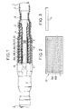
- la figure 1 représente en coupe partielle et en élévation partielle une jonction de deux câbles de puissance, selon l'invention,
- la figure 2 est une vue déployée, avant sa mise en place, d'une plaque composite de cette jonction,
- la figure 3 représente une bande en matériau adhésif, avantageusement utilisée en outre dans la jonction selon l'invention.
- FIG. 1 shows in partial section and in partial elevation a junction of two power cables, according to the invention,
- FIG. 2 is a deployed view, before its installation, of a composite plate of this junction,
- 3 shows a strip of adhesive material, advantageously used in addition in the joint according to the invention.
En se référant à la figure 1, on voit que la jonction
de câbles de puissance, comporte deux câbles haute ou
moyenne tension 1 et 2, dont les parties terminales
concernées sont dénudées, raccordées l'une à l'autre et
équipées pour leur reconstitution fonctionnelle.Referring to Figure 1, we see that the junction
power cables, has two high cables or
Ainsi que visible et référencé sur le seul câble 1,
chaque câble comporte un conducteur central 3, une isolation
4 entourant le conducteur avec une possible couche
semiconductrice entre eux, un écran semiconducteur 5 sur
l'isolation, un écran métallique 6 sur l'écran
semiconducteur et une gaine de protection extérieure 7. Les
parties terminales à raccorder des câbles sont dénudées par
élimination successive sur des longueurs convenables de la
gaine extérieure, des écrans et de l'isolation, l'écran
métallique pouvant ne pas être mis à nu du dessous de la
gaine extérieure.As visible and referenced on the single cable 1,
each cable has a central conductor 3, insulation
4 surrounding the conductor with a possible layer
semiconductor between them, a
Un raccord métallique 9, de type quelconque
convenable, relie électriquement et mécaniquement les deux
conducteurs dénudés des câbles.A
La jonction comportant ces deux câbles ainsi raccordés
comporte également une plaque composite flexible 10, qui
entoure le raccord 9 et s'étend le long de ce raccord et sur
l'extrémité de l'isolation dénudée de chaque câble, un corps
de jonction 11 qui entoure la plaque composite en place et
s'étend sur l'extrémité de l'écran semiconducteur de chaque
câble, un blindage électrique 12 qui recouvre le corps de
jonction et est relié électriquement aux écrans métalliques
des câbles et de préférence, ainsi qu'illustré, une
protection extérieure 13 qui recouvre alors le blindage et
s'étend sur les extrémités des gaines des câbles.The junction comprising these two cables thus connected
also has a flexible
La plaque composite 10 est bicouche et comprend une
couche en matériau semiconducteur ou conducteur 10A et une
couche en matériau non conducteur électriquement 10B, qui
sont superposées et solidaires l'une de l'autre. La couche
10A est de préférence en matériau élastomère semiconducteur
et formée par une plaque en ce matériau. La couche 10B est
avantageusement formée par une plaque de mastic, de
préférence de haute permittivité de l'ordre ou supérieure à
6, qui adhère directement à la plaque semiconductrice 10A.
Elle peut être en élastomère très bon isolant électrique,
pour lequel la plaque composite peut être obtenue par
coextrusion de ses deux couches.The
Cette plaque composite et flexible 10 est enroulée sur
le raccord 9 et l'extrémité de l'isolation dénudée de chaque
câble, en ayant sa couche semiconductrice 10A appliquée
contre le raccord et en contact électrique intime avec
celui-ci. Elle est prévue de longueur égale ou légèrement
supérieure à la longueur globale des deux conducteurs
dénudés et raccordés des câbles. Elle est également prévue
de largeur égale ou supérieure à la longueur périphérique du
raccord 9 utilisé et avantageusement de tout autre raccord
utilisable pour ces deux câbles ou pour d'autres câbles,
pour être enroulée sur au moins un tour complet autour du
raccord reliant les câbles concernés. Les dimensions de la
plaque composite sont définies par celles de sa couche 10B.This composite and
Le corps de jonction 11 est dans cette réalisation un
élément tubulaire tricouche, qui comprend une couche
intérieure de gradation de tension 11A, une couche
principale intermédiaire isolante 11B et une couche
extérieure semiconductrice, ces trois couches étant de même
longueur et chacune d'épaisseur uniforme et étant
avantageusement coextrudées. La couche intérieure de
gradation de tension 11A est de préférence en élastomère à
haute permittivité.The
En variante, le corps de jonction est bicouche et ne comprend que la couche principale isolante et la couche extérieure semiconductrice précitées.Alternatively, the junction body is two-layer and does not understands that the main insulating layer and the layer above-mentioned semiconductor exterior.
Le corps de jonction 11 est déformable radialement et
est de préférence mécanico-rétractable.The
Le blindage électrique 12 est également un élément
tubulaire qui est formé par un treillis métallique
élastique. La protection extérieure 13 est un manchon
élastique en élastomère isolant et est de préférence
mécanico-rétractable. Ce blindage électrique et cette
protection extérieure sont avantageusement pré-assemblés sur
le corps de jonction et l'un sur l'autre en usine, pour
constituer un ensemble alors directement mis en place sur
site sur les câbles raccordés et munis de la plaque 10
autour du raccord. The
Un exemple de réalisation de la plaque bicouche 10 est
illustré dans la figure 2, avant la mise en place de cette
plaque dans la jonction. Sa couche en matériau non
conducteur 10B est constituée par une plaque de mastic et sa
couche en matériau semiconducteur 10A est constituée par une
plaque en élastomère rendu semiconducteur, qui sont
superposées l'une sur l'autre et directement solidaires. Les
coins de la plaque semiconductrice sont tronqués pour être
sensiblement arrondis.An exemplary embodiment of the
Cette figure 2 montre que la plaque de mastic 10B est
prévue légèrement plus large et plus longue que la plaque
semiconductrice 10A. Ceci facilite la mise en place de la
plaque composite 10 autour du raccord, en permettant sa
retenue initiale par l'un ou son seul bord longitudinal
totalement en mastic, qui adhère directement au raccord et
aux extrémités des isolations dénudées des câbles, pour son
enroulement alors plus aisé autour de ce raccord et des
isolations. Ce bord est déformable et écrasé en long pour
éviter de former une transition en marche d'escalier sur le
raccord. L'autre bord longitudinal de la plaque composite
est également avantageusement en mastic uniquement, pour
être écrasé et éviter pareillement une autre transition
extérieure en marche d'escalier le long de la plaque
composite enroulée en place. Les deux bords d'extrémité de
la plaque composite sont également de préférence définis
uniquement par ceux de la plastique de mastic 10B, pour être
écrasés sur les extrémités des isolations des câbles et
ainsi définir des transitions douces entre les isolations
dénudées des câbles et la plaque composite enroulée en
place.This figure 2 shows that the
La plaque semiconductrice 10A peut être de largeur
nettement inférieure à celle de la plaque de mastic 10B en
étant toutefois supérieure à la largeur globale d'une ou de
zones longitudinales à empreintes en creux sur la périphérie
du raccord, pour recouvrir totalement et en excès cette zone
ou ces zones. Elle est centrée ou non sur la largeur de la
plaque de mastic 10B.
En variante par rapport à cette figure 2, les bords de la plaque de mastic et ceux de la plaque semiconductrice superposée se correspondent. Dans ces conditions, un pliage intérieur de l'un des bords longitudinaux de la plaque composite peut être réalisé ou une bande adhésive peut être utilisée pour permettre la retenue de ce bord sur le raccord et les extrémités des isolations dénudées des câbles et alors faciliter l'enroulement de la plaque composite autour d'eux.As a variant with respect to this FIG. 2, the edges of the putty plate and those of the semiconductor plate superimposed correspond. Under these conditions, a folding inside of one of the longitudinal edges of the plate composite can be made or an adhesive tape can be used to allow this edge to be retained on the fitting and the ends of the bare insulation of the cables and then facilitate the winding of the composite plate around of them.
Lorsque la plaque composite est formée de deux couches coextrudées, une bande adhésive ou un filet de colle peut être utilisé au début et à la fin de la mise en place de cette plaque composite, pour la retenue de l'un de ses bords longitudinaux sur le raccord et les extrémités des isolations dénudées des câbles et pour le maintien enroulé de la plaque composite en place.When the composite plate is formed of two layers coextruded, an adhesive strip or a net of glue can be used at the start and end of setting up this composite plate, for retaining one of its edges longitudinal on the fitting and the ends of the stripped insulation of cables and for rolled up maintenance of the composite plate in place.
Dans la figure 3 on a illustré une bande en matériau
adhésif 14, de préférence en mastic ordinaire collant, qui
est destinée à la fixation de la plaque composite précitée
le long du raccord. De préférence, cette bande est en même
temps utilisée pour combler des empreintes profondes sur le
raccord utilisé. Elle est alors posée en long sur de telles
empreintes et recouverte par la couche semiconductrice de la
plaque composite, cette couche semiconductrice se fixant à
la bande, pour la fixation de la bande composite, et étant
de largeur et de longueur plus grandes que celles de la
bande pour recouvrir totalement la bande et pour être par
ailleurs en contact direct avec le raccord au moins tout
autour de la bande et des éventuelles lacunes sous-jacentes
pouvant subsister au niveau des empreintes.In Figure 3 there is illustrated a strip of
Dans la jonction selon la figure 1, la plaque
composite 10 est enroulée autour du raccord sur un simple
tour complet avec recouvrement de ses bords longitudinaux.
Sa plaque ou couche extérieure en matériau non conducteur
électriquement 10B se trouve ainsi interposée entre le corps
de jonction 11 et la plaque ou couche intérieure en matériau
semiconducteur 10A. Elle permet à la fois d'éviter la
présence de bulles d'air s'étendant entre le corps de
jonction et la plaque ou couche intérieure en matériau
semiconducteur 10A et de réduire les contraintes électriques
aux extrémités de cette plaque ou couche intérieure en
matériau semiconducteur 10A.In the junction according to Figure 1, the
Outre la facilité et la rapidité de mise en place de la plaque composite, celle-ci présente l'avantage de ne nécessiter aucun outil de pose et ainsi donc d'éviter tout surcoût ou risque d'endommagement des câbles ou autres dangers.In addition to the ease and speed of setting up the composite plate, this has the advantage of not require no installation tools and therefore avoid all additional cost or risk of damage to cables or other dangers.
Cette plaque composite prévue suffisamment large s'adapte directement à différentes sections de câbles raccordés et à différents types de raccords notamment à sertir ou boulonner pouvant être utilisés, par le simple recouvrement plus ou moins important de ses bords longitudinaux ou par son enroulement sur plusieurs tours autour du raccord utilisé.This composite plate provided sufficiently wide adapts directly to different cable sections connected and to different types of fittings including crimp or bolt that can be used, by the simple more or less significant overlap of its edges longitudinal or by winding it over several turns around the fitting used.
Cette même plaque composite permet en outre l'utilisation d'un corps de jonction extrudé dépourvu de couche semiconductrice intérieure, qui lorsqu'elle est présente est éliminée le long des parties terminales du corps pour n'être laissée que sur sa partie médiane. En outre, une telle plaque composite, dont la couche en matériau non conducteur est en mastic, s'associe parfaitement à un corps de jonction mécanico-rétractable ou à l'ensemble pré-assemblé qu'il forme avec le blindage électrique et la protection extérieure, dont la pose évite l'utilisation d'une flamme susceptible de ramollir le mastic puis de le craqueler ultérieurement.This same composite plate also allows the use of an extruded junction body devoid of inner semiconductor layer, which when present is eliminated along the terminal parts of the body to be left only on its middle part. In in addition, such a composite plate, the layer of which non-conductive material is putty, associates perfectly to a mechanical-retractable junction body or to the pre-assembled assembly that it forms with the shielding electrical and external protection, the installation of which avoids the use of a flame capable of softening the putty then crack it later.
Indépendamment des avantages précédents, la jonction selon l'invention permet une amélioration très substantielle de la tenue aux claquages. Ceci est mis en évidence par des résultats de test indiqués, qui donnent les niveaux de décharges partielles avant cycles de chauffage dans des jonctions selon l'invention et dans des jonctions comparables mais comportant un tube semiconducteur ou un mastic à haute permittivité autour du raccord, à la place de la plaque composite.Regardless of the foregoing advantages, the junction according to the invention allows a very substantial improvement resistance to breakdowns. This is highlighted by indicated test results, which give the levels of partial discharges before heating cycles in junctions according to the invention and in junctions comparable but having a semiconductor tube or a high permittivity sealant around the fitting, instead of the composite plate.
Ainsi notamment, ces niveaux de décharges partielles, exprimées en pico Coulomb, restent supérieurs à 500 pC à 21 kv quand on utilise un tube semiconducteur autour d'un raccord serti et restent supérieurs à 30 pC à 21 kV et supérieurs à 50 pC à 24 kV quand on utilise un mastic à haute permittivité autour du même raccord, mais deviennent inférieurs à 5 pC à 21 kV et à 10 pC à 24 kV quand on utilise ladite plaque composite autour de ce raccord. Avec un raccord boulonné, ces niveaux restent supérieurs à 1000 pC à 21 kV, quand on utilise un tube semiconducteur autour de ce raccord, et tombent en dessous de 10 pC à 24 kV et en dessous de 5 pC à 21 kV quand on utilise la plaque composite.So in particular, these partial discharge levels, expressed in pico Coulomb, remain greater than 500 pC at 21 kv when using a semiconductor tube around a crimp connection and remain above 30 pC at 21 kV and greater than 50 pC at 24 kV when using a sealant high permittivity around the same fitting, but become lower than 5 pC at 21 kV and 10 pC at 24 kV when uses said composite plate around this fitting. With bolted connection, these levels remain above 1000 pC at 21 kV, when a semiconductor tube is used around of this fitting, and fall below 10 pC at 24 kV and in below 5 pC at 21 kV when using the plate composite.
Claims (11)
- A power cable splice including:two cables (1, 2), each of which comprises a conductor (3), insulation (4), a semiconductive screen (5), a metal screen (6), and an outer sheath (7), and has an end portion that has been stripped in successive steps;a metal connector (9) interconnecting the stripped conductors;means (10) that are electrically conductive at least in part and that surround said connector;a tubular splice body (11) surrounding said means and extending over the ends of the stripped insulation of the cables (1, 2); andelectrical shielding (12) surrounding the splice body (11) and electrically connected to the metal screens (6) of the cables (1, 2);said splice being characterized in that said means are constituted by a flexible two-layer composite plate (10) which comprises a first layer (10A) of semiconductive or conductive material, and a second layer (10B) of a material that is not electrically conductive, and which has a length not less than the length of the stripped and interconnected conductors, and a width not less than the peripheral length of said connector (9), said plate being laid along and wrapped around said connector with said first layer (10A) being in contact with the connector.
- A splice according to claim 1, characterized in that said composite plate (10) is made up of a semiconductive elastomer plate (10A) defining said first layer, and of a mastic plate (10B) defining said second layer, the two plates being mutually superposed and secured to each other.
- A splice according to claim 1 or 2, characterized in that said second layer (10B) defines the dimensions of said composite plate (10), and its length is significantly longer than that of the stripped and interconnected conductors.
- A splice according to claim 3, characterized in that said first layer (10A) has at least one of its dimensions smaller than the corresponding dimension of said second layer (10B).
- A splice according to any one of claims 2 to 4, characterized in that said mastic plate (10B) is made of a mastic having high permittivity, at least about 6.
- A splice according to claim 1, characterized in that said composite plate (10) is extruded.
- A splice according to any one of claims 1 to 6, characterized in that it further includes a strip (14) made of an adhesive material and associated with said composite plate (10) for fixing it along said connector.
- A splice according to claim 7, characterized in that said strip (14) is laid along external depressions in said connector, and it is covered by said first layer (10A) of the composite plate (10), said first layer (10A) having dimensions that are larger than those of said strip (14).
- A splice according to any one of claims 2 to 8, characterized in that said splice body (11) includes an insulating main layer (11B), a semiconductive outer layer (11C), and optionally a voltage-gradient continuous inner layer (11A) made of a material having high permittivity.
- A splice according to claim 9, characterized in that said splice body (11) is a mechanically shrink-fittable element.
- A splice according to claim 10, characterized in that said splice body (11), said electrical shielding (12) and any outer protection (13) of length greater than that of said shielding are constituted by a pre-assembled assembly that is mechanically shrink-fittable.
Applications Claiming Priority (3)
| Application Number | Priority Date | Filing Date | Title |
|---|---|---|---|
| FR9507725 | 1995-06-27 | ||
| FR9507725A FR2736218B1 (en) | 1995-06-27 | 1995-06-27 | POWER CABLES JOINING |
| PCT/FR1996/000985 WO1997001880A1 (en) | 1995-06-27 | 1996-06-24 | Junction of power cables |
Publications (2)
| Publication Number | Publication Date |
|---|---|
| EP0777926A1 EP0777926A1 (en) | 1997-06-11 |
| EP0777926B1 true EP0777926B1 (en) | 2000-03-15 |
Family
ID=9480437
Family Applications (1)
| Application Number | Title | Priority Date | Filing Date |
|---|---|---|---|
| EP96924014A Expired - Lifetime EP0777926B1 (en) | 1995-06-27 | 1996-06-24 | Junction of power cables |
Country Status (12)
| Country | Link |
|---|---|
| US (1) | US5821459A (en) |
| EP (1) | EP0777926B1 (en) |
| KR (1) | KR100394929B1 (en) |
| AU (1) | AU6496696A (en) |
| CA (1) | CA2197576C (en) |
| DE (1) | DE69607112T2 (en) |
| ES (1) | ES2144256T3 (en) |
| FR (1) | FR2736218B1 (en) |
| MY (1) | MY132283A (en) |
| TW (1) | TW301818B (en) |
| WO (1) | WO1997001880A1 (en) |
| ZA (1) | ZA965423B (en) |
Cited By (1)
| Publication number | Priority date | Publication date | Assignee | Title |
|---|---|---|---|---|
| EP1443621A1 (en) * | 2003-01-31 | 2004-08-04 | Nexans | Connection of two electrical power cables |
Families Citing this family (27)
| Publication number | Priority date | Publication date | Assignee | Title |
|---|---|---|---|---|
| DE69710903T2 (en) * | 1997-11-28 | 2002-09-19 | Nexans | External protection with interruption for high-voltage cable connection |
| US6103975A (en) * | 1998-06-29 | 2000-08-15 | 3M Innovative Properties Company | Pre-assembled electrical splice component |
| EP1009082B1 (en) * | 1998-12-10 | 2002-06-26 | Nexans | Screen connection for mechanico retractable products |
| US6378202B1 (en) * | 1999-06-29 | 2002-04-30 | Sbc Communications | Thermal shield and hermetic seal for preventing deterioration of plastic insulation in open access closures and method therefor |
| NL1014001C2 (en) * | 1999-12-31 | 2001-07-03 | Cellpack B V | Insulation sleeving method for joints between electrical cables, uses prefabricated piece of transparent netting to bind joint before forming compressive resin cover |
| DE60023533D1 (en) * | 2000-12-20 | 2005-12-01 | Nexans | cable adapter |
| US20040262025A1 (en) * | 2001-09-21 | 2004-12-30 | Konrad Brandt | Multi-part insulating cover |
| EP1506085B1 (en) * | 2002-04-23 | 2016-12-07 | CTC Global Corporation | Aluminum conductor composite core reinforced cable and method of manufacture |
| US7563983B2 (en) * | 2002-04-23 | 2009-07-21 | Ctc Cable Corporation | Collet-type splice and dead end for use with an aluminum conductor composite core reinforced cable |
| US7019217B2 (en) * | 2002-04-23 | 2006-03-28 | Ctc Cable Corporation | Collet-type splice and dead end use with an aluminum conductor composite core reinforced cable |
| US8119193B2 (en) * | 2004-10-27 | 2012-02-21 | Prysmian Cavi E Sistemi Energia S.R.L. | Method and device for coating the junction area between at least two elongated elements, in particular between electric cables |
| DE102008007405A1 (en) * | 2008-02-04 | 2009-08-06 | Tyco Electronics Raychem Gmbh | outer sleeve |
| US8445783B2 (en) * | 2009-02-05 | 2013-05-21 | 3M Innovative Properties Company | Splice assembly with shield sock |
| JP4580036B1 (en) * | 2009-06-12 | 2010-11-10 | 株式会社神戸製鋼所 | Busbar and connector |
| EP2608338B1 (en) * | 2011-12-21 | 2013-11-13 | 3M Innovative Properties Company | Terminal connection device for a power cable |
| FR2991808B1 (en) * | 2012-06-08 | 2015-07-17 | Nexans | DEVICE COMPRISING A TRAPPER LAYER OF SPACE LOADS |
| US9425605B2 (en) | 2013-03-14 | 2016-08-23 | Tyco Electronics Corporation | Method for protecting a cable splice connection with a cover assembly |
| WO2014209739A1 (en) * | 2013-06-26 | 2014-12-31 | 3M Innovative Properties Company | Power cable terminal connection device |
| FR3010248B1 (en) * | 2013-09-05 | 2017-03-31 | Nexans | DEVICE FOR JUNCTION OF HYBRID ELECTRIC TRANSPORT CABLES |
| CA2968604C (en) * | 2014-11-25 | 2022-06-07 | Nkt Hv Cables Gmbh | Jointed power cable and method of manufacturing the same |
| US9786412B2 (en) * | 2015-03-19 | 2017-10-10 | Te Connectivity Corporation | Cable moisture seal assemblies, systems and methods |
| US9780549B2 (en) * | 2015-09-17 | 2017-10-03 | Te Connectivity Corporation | Cover assemblies and methods for covering electrical cables and connections |
| CN106898995A (en) * | 2015-12-17 | 2017-06-27 | 江苏澳能电力电缆附件有限公司 | Joint after a kind of separable cable terminal |
| CN106898996A (en) * | 2015-12-17 | 2017-06-27 | 江苏澳能电力电缆附件有限公司 | A kind of separable cable terminal front connector |
| CN105811352A (en) * | 2016-03-03 | 2016-07-27 | 江苏中天科技电缆附件有限公司 | Novel type single-phase cable branch box |
| US10389103B2 (en) | 2016-10-18 | 2019-08-20 | Te Connectivity Corporation | Breakout boot assemblies and methods for covering electrical cables and connections |
| US9954320B1 (en) * | 2017-01-23 | 2018-04-24 | Ford Global Technologies, Llc | Cable connector |
Family Cites Families (19)
| Publication number | Priority date | Publication date | Assignee | Title |
|---|---|---|---|---|
| US2436519A (en) * | 1943-10-11 | 1948-02-24 | Gen Foods Corp | Manufacture of flaked cereal-soya product |
| US3349164A (en) * | 1965-12-28 | 1967-10-24 | Minnesota Mining & Mfg | Insulative stress relief film |
| US3412200A (en) * | 1966-12-08 | 1968-11-19 | Asea Ab | High voltage cable with potential gradient equalization means |
| US3673311A (en) * | 1969-10-22 | 1972-06-27 | Joslyn Mfg & Supply Co | Corona free coupling assembly for coaxial cables |
| US3717717A (en) * | 1970-04-20 | 1973-02-20 | Joslyn Mfg & Supply Co | Shrinkable cable joint sleeve, cable joint employing the same, and method of forming a cable joint |
| US3692922A (en) * | 1971-04-06 | 1972-09-19 | Yoichi Sugimoto | Cable joint with high voltage stress relief |
| US3777048A (en) * | 1971-09-22 | 1973-12-04 | Kaiser Aluminium Chem Corp | Molding process for splicing cable and product formed thereby |
| US3952604A (en) * | 1974-07-15 | 1976-04-27 | Baudler James P | Device for converting linear motion to rotary motion |
| US4006288A (en) * | 1974-12-30 | 1977-02-01 | Amerace Corporation | High voltage shielded cable termination, splice connection, and method of making a splice connection |
| US4164620A (en) * | 1978-09-07 | 1979-08-14 | Minnesota Mining And Manufacturing Company | Insulative corona discharge suppressing sheath for high voltage cable splices |
| US4383131A (en) * | 1978-09-14 | 1983-05-10 | Raychem Limited | Shielded electrical cable joints and terminations and sleeve and method for forming same |
| US4487994A (en) * | 1981-11-09 | 1984-12-11 | Cable Technology Laboratories, Ltd. | Electrical cable joint structure and method of manufacture |
| US4555588A (en) * | 1983-10-26 | 1985-11-26 | Rte Corporation | Heat transfer device for electrical connector in insulating housing of high voltage splice or terminator |
| IT1175762B (en) * | 1984-09-28 | 1987-07-15 | Pirelli Cavi Spa | EXTRUDED INSULATION CABLE JOINT |
| FR2593335B1 (en) * | 1986-01-22 | 1988-07-22 | Pirelli Treficable | DEVICE FOR CONNECTING TWO INSULATED ELECTRICAL CABLES INCLUDING IMPROVED EXTERNAL JUNCTION PROTECTION MEANS |
| US5043538A (en) * | 1989-07-03 | 1991-08-27 | Southwire Company | Water resistant cable construction |
| FR2679712B1 (en) * | 1991-07-24 | 1995-04-14 | Alcatel Cable | CONNECTION ASSEMBLY OF TWO HIGH OR VERY HIGH VOLTAGE CABLES. |
| JP2734835B2 (en) * | 1991-09-12 | 1998-04-02 | 日立電線株式会社 | Cable shield insulation type plug-in straight connection |
| JP3014542B2 (en) * | 1992-07-03 | 2000-02-28 | 古河電気工業株式会社 | Method of connecting crosslinked rubber / plastic insulated power cable and electric field relaxation tape used therefor |
-
1995
- 1995-06-27 FR FR9507725A patent/FR2736218B1/en not_active Expired - Lifetime
-
1996
- 1996-06-24 CA CA002197576A patent/CA2197576C/en not_active Expired - Fee Related
- 1996-06-24 DE DE69607112T patent/DE69607112T2/en not_active Expired - Lifetime
- 1996-06-24 KR KR1019970701274A patent/KR100394929B1/en not_active IP Right Cessation
- 1996-06-24 EP EP96924014A patent/EP0777926B1/en not_active Expired - Lifetime
- 1996-06-24 US US08/793,514 patent/US5821459A/en not_active Expired - Fee Related
- 1996-06-24 WO PCT/FR1996/000985 patent/WO1997001880A1/en active IP Right Grant
- 1996-06-24 ES ES96924014T patent/ES2144256T3/en not_active Expired - Lifetime
- 1996-06-25 MY MYPI96002569A patent/MY132283A/en unknown
- 1996-06-26 AU AU64966/96A patent/AU6496696A/en not_active Abandoned
- 1996-06-26 ZA ZA965423A patent/ZA965423B/en unknown
- 1996-07-16 TW TW085108628A patent/TW301818B/zh active
Cited By (2)
| Publication number | Priority date | Publication date | Assignee | Title |
|---|---|---|---|---|
| EP1443621A1 (en) * | 2003-01-31 | 2004-08-04 | Nexans | Connection of two electrical power cables |
| FR2850802A1 (en) * | 2003-01-31 | 2004-08-06 | Nexans | CONNECTION OF TWO ELECTRIC POWER CABLES |
Also Published As
| Publication number | Publication date |
|---|---|
| AU6496696A (en) | 1997-01-30 |
| MY132283A (en) | 2007-09-28 |
| WO1997001880A1 (en) | 1997-01-16 |
| TW301818B (en) | 1997-04-01 |
| US5821459A (en) | 1998-10-13 |
| DE69607112T2 (en) | 2000-10-12 |
| EP0777926A1 (en) | 1997-06-11 |
| ES2144256T3 (en) | 2000-06-01 |
| CA2197576A1 (en) | 1997-01-16 |
| DE69607112D1 (en) | 2000-04-20 |
| CA2197576C (en) | 2006-08-08 |
| FR2736218A1 (en) | 1997-01-03 |
| FR2736218B1 (en) | 1997-08-01 |
| KR100394929B1 (en) | 2003-12-01 |
| ZA965423B (en) | 1997-01-31 |
Similar Documents
| Publication | Publication Date | Title |
|---|---|---|
| EP0777926B1 (en) | Junction of power cables | |
| FR2624665A1 (en) | ELECTRICAL SEALING MATERIAL IN THE SURROUNDING MEDIUM AND SEALING METHOD USING THE SAME | |
| EP3526868A1 (en) | Underwater electrical connection system | |
| EP2193529B1 (en) | Sheath providing protection against radiation, in particular from the electric field generated by electric cables | |
| CH626754A5 (en) | Method for joining high-voltage cables and device for implementing this method | |
| CA2572944C (en) | Protective sheath against radiation, in particular derived from electric field generated by electric cables | |
| FR2685141A1 (en) | JUNCTION OF ELECTRIC CABLES, PREFERRED JUNCTION ASSEMBLY AND METHOD FOR IMPLEMENTING THE SAME. | |
| FR2710204A1 (en) | Accessory equipment for connecting an energy cable and power cable thus equipped. | |
| CH621653A5 (en) | ||
| FR2576465A1 (en) | JOINT FOR ELECTRIC CABLES, IN PARTICULAR FOR HIGH VOLTAGE | |
| EP0797281B1 (en) | Process and assembly for mounting tightly a resilient tubular covering on an element | |
| EP0281896B1 (en) | Flexible joint for an under-water cable provided with paper impregnation | |
| EP0943099B1 (en) | Protective pipe element for sheathed cable for verifying the integrity of the sheath | |
| FR2468189A1 (en) | ELECTRIC CABLE PROTECTED AGAINST MOISTURE | |
| EP0862801B1 (en) | Electrical coupling part | |
| FR2852746A1 (en) | High voltage electric power underground transmission system, has metallic shield integrated along internal cavity of installation pipe for grounding and being independent of electric power cable | |
| EP2897227B1 (en) | Metal braid for earthing a screen of an electric cable | |
| EP3062407B1 (en) | Coupling sleeve between conductive cables, manufacturing process and implementing process for such a sleeve. | |
| EP0913903B1 (en) | Outdoor power cable end | |
| FR2984030A1 (en) | Connection kit for connecting low voltage network cables, has insulating sheaths covering mechanical connection elements, holding body adapted to cover assembly of connection elements, and outer protection cover covering body | |
| CA2238260C (en) | Electrical coupling part | |
| FR2760146A1 (en) | Protecting and waterproofing sleeve for cable termination | |
| EP1585204A1 (en) | High-voltage power transmission system | |
| EP4213322A1 (en) | Connection assembly between two electrical cables | |
| FR2752106A1 (en) | Self supporting termination for high tension power cable |
Legal Events
| Date | Code | Title | Description |
|---|---|---|---|
| PUAI | Public reference made under article 153(3) epc to a published international application that has entered the european phase |
Free format text: ORIGINAL CODE: 0009012 |
|
| AK | Designated contracting states |
Kind code of ref document: A1 Designated state(s): BE DE ES GB IT NL SE |
|
| 17P | Request for examination filed |
Effective date: 19970716 |
|
| GRAG | Despatch of communication of intention to grant |
Free format text: ORIGINAL CODE: EPIDOS AGRA |
|
| 17Q | First examination report despatched |
Effective date: 19990504 |
|
| GRAG | Despatch of communication of intention to grant |
Free format text: ORIGINAL CODE: EPIDOS AGRA |
|
| GRAH | Despatch of communication of intention to grant a patent |
Free format text: ORIGINAL CODE: EPIDOS IGRA |
|
| GRAH | Despatch of communication of intention to grant a patent |
Free format text: ORIGINAL CODE: EPIDOS IGRA |
|
| RAP1 | Party data changed (applicant data changed or rights of an application transferred) |
Owner name: ALCATEL |
|
| GRAA | (expected) grant |
Free format text: ORIGINAL CODE: 0009210 |
|
| AK | Designated contracting states |
Kind code of ref document: B1 Designated state(s): BE DE ES GB IT NL SE |
|
| REF | Corresponds to: |
Ref document number: 69607112 Country of ref document: DE Date of ref document: 20000420 |
|
| GBT | Gb: translation of ep patent filed (gb section 77(6)(a)/1977) |
Effective date: 20000407 |
|
| ITF | It: translation for a ep patent filed |
Owner name: JACOBACCI & PERANI S.P.A. |
|
| REG | Reference to a national code |
Ref country code: ES Ref legal event code: FG2A Ref document number: 2144256 Country of ref document: ES Kind code of ref document: T3 |
|
| PLBE | No opposition filed within time limit |
Free format text: ORIGINAL CODE: 0009261 |
|
| STAA | Information on the status of an ep patent application or granted ep patent |
Free format text: STATUS: NO OPPOSITION FILED WITHIN TIME LIMIT |
|
| 26N | No opposition filed | ||
| NLS | Nl: assignments of ep-patents |
Owner name: NEXANS |
|
| REG | Reference to a national code |
Ref country code: GB Ref legal event code: 732E |
|
| REG | Reference to a national code |
Ref country code: GB Ref legal event code: IF02 |
|
| PGFP | Annual fee paid to national office [announced via postgrant information from national office to epo] |
Ref country code: BE Payment date: 20080728 Year of fee payment: 13 |
|
| BERE | Be: lapsed |
Owner name: *NEXANS Effective date: 20090630 |
|
| PG25 | Lapsed in a contracting state [announced via postgrant information from national office to epo] |
Ref country code: BE Free format text: LAPSE BECAUSE OF NON-PAYMENT OF DUE FEES Effective date: 20090630 |
|
| PGFP | Annual fee paid to national office [announced via postgrant information from national office to epo] |
Ref country code: NL Payment date: 20100614 Year of fee payment: 15 |
|
| PGFP | Annual fee paid to national office [announced via postgrant information from national office to epo] |
Ref country code: SE Payment date: 20100614 Year of fee payment: 15 Ref country code: GB Payment date: 20100618 Year of fee payment: 15 |
|
| REG | Reference to a national code |
Ref country code: NL Ref legal event code: V1 Effective date: 20120101 |
|
| REG | Reference to a national code |
Ref country code: SE Ref legal event code: EUG |
|
| GBPC | Gb: european patent ceased through non-payment of renewal fee |
Effective date: 20110624 |
|
| PG25 | Lapsed in a contracting state [announced via postgrant information from national office to epo] |
Ref country code: NL Free format text: LAPSE BECAUSE OF NON-PAYMENT OF DUE FEES Effective date: 20120101 |
|
| PG25 | Lapsed in a contracting state [announced via postgrant information from national office to epo] |
Ref country code: GB Free format text: LAPSE BECAUSE OF NON-PAYMENT OF DUE FEES Effective date: 20110624 |
|
| PG25 | Lapsed in a contracting state [announced via postgrant information from national office to epo] |
Ref country code: SE Free format text: LAPSE BECAUSE OF NON-PAYMENT OF DUE FEES Effective date: 20110625 |
|
| PGFP | Annual fee paid to national office [announced via postgrant information from national office to epo] |
Ref country code: IT Payment date: 20140626 Year of fee payment: 19 Ref country code: DE Payment date: 20140619 Year of fee payment: 19 Ref country code: ES Payment date: 20140627 Year of fee payment: 19 |
|
| REG | Reference to a national code |
Ref country code: DE Ref legal event code: R119 Ref document number: 69607112 Country of ref document: DE |
|
| PG25 | Lapsed in a contracting state [announced via postgrant information from national office to epo] |
Ref country code: IT Free format text: LAPSE BECAUSE OF NON-PAYMENT OF DUE FEES Effective date: 20150624 |
|
| PG25 | Lapsed in a contracting state [announced via postgrant information from national office to epo] |
Ref country code: DE Free format text: LAPSE BECAUSE OF NON-PAYMENT OF DUE FEES Effective date: 20160101 |
|
| REG | Reference to a national code |
Ref country code: ES Ref legal event code: FD2A Effective date: 20160728 |
|
| PG25 | Lapsed in a contracting state [announced via postgrant information from national office to epo] |
Ref country code: ES Free format text: LAPSE BECAUSE OF NON-PAYMENT OF DUE FEES Effective date: 20150625 |