EP0777094A2 - Heat exchanging element - Google Patents
Heat exchanging element Download PDFInfo
- Publication number
- EP0777094A2 EP0777094A2 EP96118887A EP96118887A EP0777094A2 EP 0777094 A2 EP0777094 A2 EP 0777094A2 EP 96118887 A EP96118887 A EP 96118887A EP 96118887 A EP96118887 A EP 96118887A EP 0777094 A2 EP0777094 A2 EP 0777094A2
- Authority
- EP
- European Patent Office
- Prior art keywords
- heat exchanging
- corrugated
- corrugations
- exchanging element
- sheet
- Prior art date
- Legal status (The legal status is an assumption and is not a legal conclusion. Google has not performed a legal analysis and makes no representation as to the accuracy of the status listed.)
- Withdrawn
Links
Images


Classifications
-
- F—MECHANICAL ENGINEERING; LIGHTING; HEATING; WEAPONS; BLASTING
- F28—HEAT EXCHANGE IN GENERAL
- F28F—DETAILS OF HEAT-EXCHANGE AND HEAT-TRANSFER APPARATUS, OF GENERAL APPLICATION
- F28F3/00—Plate-like or laminated elements; Assemblies of plate-like or laminated elements
- F28F3/02—Elements or assemblies thereof with means for increasing heat-transfer area, e.g. with fins, with recesses, with corrugations
- F28F3/025—Elements or assemblies thereof with means for increasing heat-transfer area, e.g. with fins, with recesses, with corrugations the means being corrugated, plate-like elements
-
- F—MECHANICAL ENGINEERING; LIGHTING; HEATING; WEAPONS; BLASTING
- F24—HEATING; RANGES; VENTILATING
- F24F—AIR-CONDITIONING; AIR-HUMIDIFICATION; VENTILATION; USE OF AIR CURRENTS FOR SCREENING
- F24F12/00—Use of energy recovery systems in air conditioning, ventilation or screening
- F24F12/001—Use of energy recovery systems in air conditioning, ventilation or screening with heat-exchange between supplied and exhausted air
- F24F12/006—Use of energy recovery systems in air conditioning, ventilation or screening with heat-exchange between supplied and exhausted air using an air-to-air heat exchanger
-
- F—MECHANICAL ENGINEERING; LIGHTING; HEATING; WEAPONS; BLASTING
- F28—HEAT EXCHANGE IN GENERAL
- F28D—HEAT-EXCHANGE APPARATUS, NOT PROVIDED FOR IN ANOTHER SUBCLASS, IN WHICH THE HEAT-EXCHANGE MEDIA DO NOT COME INTO DIRECT CONTACT
- F28D9/00—Heat-exchange apparatus having stationary plate-like or laminated conduit assemblies for both heat-exchange media, the media being in contact with different sides of a conduit wall
- F28D9/0025—Heat-exchange apparatus having stationary plate-like or laminated conduit assemblies for both heat-exchange media, the media being in contact with different sides of a conduit wall the conduits being formed by zig-zag bend plates
-
- Y—GENERAL TAGGING OF NEW TECHNOLOGICAL DEVELOPMENTS; GENERAL TAGGING OF CROSS-SECTIONAL TECHNOLOGIES SPANNING OVER SEVERAL SECTIONS OF THE IPC; TECHNICAL SUBJECTS COVERED BY FORMER USPC CROSS-REFERENCE ART COLLECTIONS [XRACs] AND DIGESTS
- Y02—TECHNOLOGIES OR APPLICATIONS FOR MITIGATION OR ADAPTATION AGAINST CLIMATE CHANGE
- Y02B—CLIMATE CHANGE MITIGATION TECHNOLOGIES RELATED TO BUILDINGS, e.g. HOUSING, HOUSE APPLIANCES OR RELATED END-USER APPLICATIONS
- Y02B30/00—Energy efficient heating, ventilation or air conditioning [HVAC]
- Y02B30/56—Heat recovery units
Definitions
- the present invention relates to a heat exchanging element which is used in a heat exchanger type ventilating device or an air conditioning unit.
- a conventional heat exchanging element is designed so that air supplied from outdoor is substantially perpendicular to air discharged from indoor as shown in Figure 27.
- reference numeral 1 designates the heat exchanging element
- reference numeral 110 designates flat partitions which are made of a material having heat-conducting ability and moisture permeability
- reference numeral 111 designates spacers which have a corrugated form in section.
- the partitions 110 and the spacers 111 are alternately layered, and the respective spacers 111 are arranged to be turned through 90° with respect to their adjoined spacers.
- Reference numeral 112 and 113 designate supplied air openings and discharged air openings, respectively, which are formed by layering.
- the supplied air from outdoor is flowed in a direction indicated by shaded arrows, and discharged air from indoor is flowed in a direction indicated by unshaded arrows to carry out heat exchange, recovering heat.
- the heat exchange is carried out primarily through the partitions 110, and the area which is effective in the heat exchange includes the area of the partitions and small portions of the spaces.
- the primary function of the spacers 111 is to provide required spaces between adjoining partitions 110. The reason why the small portions of the spacers 111 contribute to the heat exchange is that such portions of the spacers work as fins for the partitions.
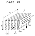
- FIG. 28 there is shown a perspective view of a schematic structure of the heat exchanging element according to the proposal.
- reference numeral 202 designates a partition
- reference numeral 203 designates spacers on inlet sides
- reference numeral 204 designates spacers on outlet sides.
- the heat exchanging element 1 is constituted by the partition 202 and the spacers 203 and 204, and the partitions and the spacers are alternately layered.
- the supplied air indicated by shaded arrows enters at the front side on Figure 28 and flows out downwardly.
- the discharged air enters at the rear side on this Figure and then flows out upwardly at the front side on this Figure as indicated in unshaded arrows.
- the supplied air and the discharged air are arranged in an opposed flow pattern through the partition 202 to carry out heat exchange.
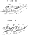
- FIG 29 there is shown a view of the partition 202 of the heat exchanging element 1 which is unfolded.
- a sheet having a width A is used as the partition 202.
- the partition 202 is an elongated article, and the partition 202 has the spacers 203 on the respective inlet sides and the spacers 204 on the respective outlet sides bonded to opposed surfaces thereof.
- the partition 202 has pairs of the spacers 203 and the spacers 204 alternately bonded to the opposed surfaces.
- the partitions has pairs of folds 205 arranged thereon so that the folds in each pair are apart from each other by a gap C between a portion thereof with spacers 203 and 204 bonded thereon and having a length B, and it adjoining portion with spacers 203 and 204 bonded thereon and having a length B.
- the partition 202 is zigzag bent at the folds 205 to form the heat exchanging element 1 shown in Figure 28.
- Figure 30 it is shown what positions the spacers 203 and 204 occupy during zigzag bending the partition 202 at the folds 205. Because the partition 202 is folded at predetermined intervals and layered, the pairs of the spacers 203 and 204 have to be alternately bonded on the opposed surfaces of the partition. Such an arrangement does not allow the spacers 203 and 204 to be continuous parts, respectively. The respective spacers are required to individually bonded. This means that there is an increase in the number of required parts for fabrication of the heat exchanging element and that discontinuous bonding processes are required.
- the spacers 203 and 204 have a primary function to hold a space for the partition 202, and the supplied air and the discharged air carries out little heat exchange through the spacers 203 and 204.
- the area which is effective for heat exchange includes the flat partition 202 and small portions of the spacers 203 and 204. This means that a significant advantage can not be obtained though the crossflow structure can make the size smaller.
- the heat exchanging element shown in Figure 28 wherein the supplied air and the discharged air flow in the opposite directions and the partition is zigzag bent in the layered structure involves two main problems.
- One is that the supplied air and the discharged air carry out heat exchange through the flat partition but carry out no heat exchange through the corrugated spacers.
- the main purpose of the spacers is to ensure a required space for the partition to provide the air flow passages, which creates a problem in that only a small heat exchanging area is obtained in single use of the flat partition for heat exchange.
- the spacers for ensuring the required space are separable parts each other. It creates problems in that an increase in the number of parts required for the spacers raises cost, and that production is difficult because the spacers are individually and alternately bonded to the opposed surfaces of the partition.
- the present invention provides a heat exchanging element which comprising a sheet and a corrugated portion formed on the sheet, wherein the sheet is zigzag bent in a layered structure to provide a first air flow passage and a second air flow passage which carry out heat exchange therebetween.
- the corrugated portion may be continuously formed on the sheet.
- the sheet may comprise corrugated surface portions and flat surface portions, each corrugated surface portion having the corrugated portion formed thereon, the corrugated surface portions and the flat surface portions being alternately layered.
- the corrugated portion may have corrugations formed at predetermined intervals.
- Bend end surfaces of the sheet which is zigzag bent may be in parallel with the passages formed at the corrugated portion.
- the corrugated portion may have opposed leading edges of the corrugations tapered.
- the sheet may have a surface in parallel with a corrugating direction of the corrugated portion formed with smaller corrugations than the corrugated portion.
- the number of the smaller corrugations may be odd times that of the corrugations of the corrugated portion.
- the sheet may have a side edge formed with side edge corrugations to provide spaces for the passages.
- the side edge corrugations may have a corrugating direction in parallel with that of the corrugated portion.
- the side edge corrugations may have a corrugating direction perpendicular to that of the corrugated portion.
- the corrugated portion may have corrugations formed so that the first and second passages formed by the corrugated portion can have air flows equalized therein.
- the corrugated portion may have the respective corrugations pinched to be crushed by a predetermined length from the top of the respective corrugations over the entire length of the passages.
- the corrugated portion may have the respective corrugations formed so that one of adjoining passages has a longer pinched portions than the other passage.
- the corrugated portion, and portions of the sheet which get in touch with the corrugations of the corrugated portion in the layered structure have convexed portions and concave portions formed thereon so as to be engaged each other.
- the sheet may have metal members included therein.
- the metal members may be one of aluminum, iron, copper, stainless steel and nickel.
- the metal members may be formed in one of a predetermined width of foil, thin wire or mesh.
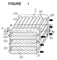
- FIG. 1 there is shown a schematic perspective view of the heat exchanging element according to a first embodiment of the present invention.
- reference numeral 2 designates a partition which is formed by zigzag bending a single sheet at intervals of a suitable length so as to provide a layered structure.
- Reference numeral 20 designates a corrugated portion which is provided on the partition 2, which is shaped by corrugating opposed central surfaces of the sheet, and which has both central surfaces provided with passages extended from one side edge to the other side edge.
- the partition 2 is zigzag bent to alternately arrange open ends and closed ends at both end portions of the heat exchange element 1.
- Reference numeral 21 designates a supplied air inlet which is provided in an open portion at a front side on the figure.
- the open portion is defined by the corrugated portion 20 at the open ends at one of the side portions of the heat exchanging element 1.
- Reference numeral 22 designates a supplied air outlet which is provided in an open portion at a rear side on the figure.
- the rear open portion is defined by the corrugated portion 20 at the open ends at the other side portion of the heat exchanging element.
- Reference numeral 23 designates a discharged air inlet which is provided in an open portion at a rear side on the figure.
- the opened portion with the discharged air inlet is defined by the corrugated portion 20 at the open ends at the other side portion of the heat exchanging element.
- Reference numeral 24 designates a discharged air outlet which is provided in an open portion at a front side on the figure.
- the open portion with the discharged air outlet is defined by the corrugated portion 20 at the open ends at the one side portion of the heat exchanging element.
- Reference numerals 25 and 26 designate side end seals which are separated from both side portions of the heat exchanging element corresponding to the side edges of the sheet, and which close both side portions.
- Such arrangement allows supplied air passages as first air passages and discharged air passages as second air passages to be isolated by the partition 2, and the respective passages to ensure and obtain required gaps by only the partition 2 without help of spacers.
- a sine wave, a trapezoidal wave or a rectangular wave can be adopted as the wave form of the corrugated portion 20
- the wave form of the corrugated portion is not limited to these wave forms.
- the corrugated portion works as spacers to ensure the first air passages and the second air passages.
- the corrugated portion is shaped in a wave form of corrugations which is used in e.g. corrugated paper and is good at strength.
- FIG 2 there is shown a perspective view of a portion of the partition 2 constituting the heat exchanging element 1, which has been unfolded in a flat manner.
- the partition 2 has the corrugated portion 20 continuously formed at a central portion of the sheet.
- the corrugated portion 20 is formed in such a manner that a flat sheet, such as Japanese paper and converted paper, which is commonly used as a heat exchanging element partition, has a central portion pressed to provide continuous corrugations without cutting the sheet into short pieces, thereby providing equal corrugations on both surfaces of the sheet.
- Reference numeral 29 designates flat side portions which are left flat on both sides of the sheet.
- Boarders between the corrugated portion 20 and the flat side portions 29 are formed so that leading portions of the corrugations in proximity to the flat side portions are tapered in order to prevent the sheet from being broken on shaping. If the sheet is too tough to be broken, it is not necessary to taper the leading portion of the corrugations.
- the partition 2 according to this embodiment is formed so as to have an equal structure in its entirety. Since the partition is bendable at any locations, the sheet can be zigzag bent at any locations. As a result, forming the corrugated portion 20 can be successively carried out on the sheet. Whichever portion of the sheet is cut at to start zigzag bending, the heat exchanging element 1 can be fabricated to extremely facilitate manufacturing and working.
- the distance between adjoining corrugations is determined so that when the sheet is zigzag bent, the tops of confronting corrugations of the corrugated portion 20 contact with each other. When the sheet has been layered as stated, the tops of the confronting corrugations of the corrugated portion 20 are jointed together to provide the passages between the corrugations of the jointed corrugated portion 20.
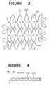
- FIG 3 there is shown a vertical section of the heat exchanging element 1 of Figure 1, taken along the line III-III.
- the corrugated portion 20 is formed so that the corrugations are repeated upwardly and downwardly on both surfaces with respect to the sheet plane, and that the tops of the confronting corrugations are jointed to alternately upwardly and downwardly provide the supplied air passages 30 (indicated by symbols "X") and the discharged air passages 31 (indicated by symbols " ⁇ ") between the adjoining corrugations.
- the sheet has side portions at the front and rear sides in Figure 1 formed with the flat portions 29, and the shape of the flat portions is flat as shown in Figure 4 which is a vertical section taken along the line IV-IV of Figure 1.
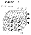
- FIG 5 there is shown a perspective view of the section of the heat exchanging element 1 taken along the line III-III of Figure 1. Portions of the zigzag bent corrugated portions 20 which are formed with folds have the passages therein crushed to be finally bonded to the sheet, increasing air tightness.
- each layer has one end closed.
- the side edges of the sheet are closed by the side end seals 25 and 26.
- Each layer has only an end portion remote from the zigzag bend fold worked as the open end.
- the heat exchanging element has the respective open ends and the respective zigzag bend folds alternately arranged in the vertical direction.
- the passages formed by the corrugated portion 20 are the ones that the respective passages have both ends communicated with respective open end portions through both flat portions 29.
- the supplied air passages are formed to extend from the supplied air inlet 21 to the supplied air outlet 22 through the corrugated portion 20, and the discharged air passages are formed to extend from the discharged air inlet 23 to the discharged air outlet 24 through the corrugated portion 20.
- FIG 6 there is shown a cross-sectional of a ceiling mounted and concealed type total heat exchanging unit with a heat exchanging element of Figure 1 incorporated thereinto.
- reference numeral 100 designates a ceiling mounted and concealed type total heat exchanging unit main body.
- Reference numeral 1 designates the heat exchanging element which is incorporated into a central portion of the total heat exchanging unit.
- Reference numeral 5 designates an air supplying fan which is constituted by a centrifugal fan, and which has an inlet communicated with the supplied air outlet 22 of the heat exchanging element 1.
- Reference numeral 6 designates an air discharging fan which is constituted by a centrifugal fan, and which has an inlet communicated with the discharged air outlet 24 of the heat exchanging element 1.
- Reference numeral 7 designates a supplied air inlet port which is connected to outdoors, and which communicates with the supplied air inlet 21 of the heat exchanging element 1.
- Reference numeral 8 designates a supplied air outlet port which communicates with an outlet of the air supplying fan 5, and which is connected to indoors.
- Reference numeral 9 designates a discharged air inlet port which is connected to indoors, and which communicates with the discharged air inlet 23 of the heat exchanging element 1.
- Reference numeral 10 designates a discharged air outlet port which communicates with an outlet of the air discharging fan 6, and which is connected to outdoors.
- Reference numeral 3 designates a supplied air flow
- reference numeral 4 designates a discharge air flow.
- the supplied air inlet port 7, the supplied air outlet port 8, the discharged air inlet port 9 and the discharged air outlet port 10 are connected to e.g. ducts to properly lead indoors and outdoors through duct piping.
- supplied air from outdoors flows from the supplied air inlet port 7 into the supplied air inlet 21 of the heat exchanging element 1, passes through the corrugated portion 20 and flows out of the supplied air outlet 22 to indoors through the supplied air outlet port 8.
- Discharged air from indoors flows from the discharged air inlet port 9 into the discharged air inlet 23 of the heat exchanging element 1, passes through the corrugated portion 20 and flows out of the discharged air outlet 24 to outdoors through the discharged air outlet port 10.
- the partition 2 can be corrugated to increase a heat exchanging area per unit volume in comparison with the conventional flat partition, improving heat exchanging efficiency. Since the heat exchanging element is layered by using only the partition, machining and assembling are easy. The corrugated portion which works as spacers can be also contributed to heat exchange to go no waste. When the corrugated portion is continuously formed like this embodiment, cutting can be made at any locations. No need for intermittent pressing can facilitate production and decrease cost.
- the side edges of the passages formed by the corrugated portion are sealed by folds in a seamless manner to improve airtightness.
- opposite sides of the end portions which have the open ends and the folds alternately formed by zigzag bending work as the air inlets and the air outlets, and the supplied air and the discharged air turn at 90° to pass through the corrugated portion like this embodiment, the opposite sides of the end portions with the air inlets and the air outlets have no need for special sealing between the different air flow layers, facilitating production.
- FIG 7 there is shown a schematic perspective view of the heat exchanging element according to another embodiment of the present invention.
- reference numeral 2 designates a partition which is formed by zigzag bending a single sheet at intervals of a suitable length so as to provide a layered structure.
- Reference numeral 20 designates a corrugated portion which is provided on the partition 2. The corrugated portion 20 is shaped by corrugating opposed central surfaces of the sheet so as to provide corrugated sections in a longitudinal direction except for folds which are formed when the sheet is zigzag bent.
- the partition 2 is also provided with flat surface sections 57 between corrugated sections.
- the corrugated sections 20 and the flat surface portions 57 are alternately layered to ensure required gaps, having opposite surfaces of the sheet provided with passages extended from one side edge to the other side edge of the sheet.
- Such arrangement allows the supplied air passages as the first air passages and the discharged air passages as the second air passages to be isolated by the partition 2, and the respective passages to be ensured only by the partition 2 without using spacers.
- the sine wave, a trapezoidal wave or a rectangular wave can be adopted as the wave form of the corrugated sections 20, the wave form of the corrugated sections is not limited to these wave forms.
- the corrugated sections work as the spacers to ensure the first air passages and the second air passages.
- the corrugated sections are shaped in a wave form of corrugations which is used in e.g. corrugated paper and is good at strength.
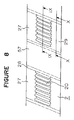
- FIG 8 there is shown a perspective view of a portion of the partition 2 constituting the heat exchanging element 1, which has been unfolded in a flat manner.
- the partition 2 has a central portion of the sheet formed with the corrugated sections 20 with a certain number of continuous corrugations at intervals of a certain length.
- the corrugated sections 20 are formed in such a manner that a flat sheet, such as Japanese paper and converted paper, which is commonly used as a heat exchanging element partition, has a central portion intermittently pressed to provide the discontinuous corrugated sections without cutting the sheet into short pieces, thereby providing similar corrugations on both surfaces of the sheet.
- Reference numeral 29 designates the flat side portions which are left flat on both sides of the sheet. Boarders between the corrugated sections 20 and the flat side portions 29 may be formed so that leading portions of the corrugations in proximity to the flat side portions are tapered in order to prevent the sheet from being broken on shaping.
- Reference numeral 57 designates the flat surface portions which are uncorrugated on the sheet, which has the same length as the corrugated sections 20, and which have a length equal to that of flat surface portions except for the folds which are formed when the sheet is zigzag bent.
- Reference numeral 28 designates a gap which works as a fold when the sheet is bent.
- the sheet shown in Figure 8 is formed so that the corrugated surface portions 27 with flat side portions 29 and a corrugated section 20, and the flat surface portions 57 are alternately arranged interposing each gap 28 therebetween so as to provide a cyclic chain.
- the sheet may be cut into pieces of a suitable length before being layered, or be cut after being layered.
- the corrugated surface portions 27 and the flat surface portions 57 are alternately layered by zigzag bending the partition at each gap 28, and the tops of the respective corrugations of the corrugated sections 20 are jointed to the flat surface portions 57 which the tops get in touch with when the corrugated surface portions and the flat surface portions are layered.
- Such arrangement can joint the tops of the respective corrugations and the flat surfaces without jointing the confronting tops of the corrugations like the first embodiment.
- jointing the corrugated sections does not require high accuracy unlike the first embodiment, facilitating assembly. Since the second embodiment have no need for spacers like the first embodiment, manufacturing and machining can be carried out in an extremely easy manner.
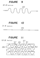
- FIG 9 there is shown a vertical section of a portion of the partition 2 shown in Figure 8, taken along the line IX-IX.
- the respective corrugated sections 20 are formed so that the corrugations are repeated upwardly and downwardly on both surfaces with respect to the sheet plane.
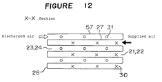
- the tops of the respective corrugations are jointed to the flat surface portions 57 to alternately arrange the supplied air passages 30 and the discharged air passages 31 between the corrugations as shown in Figure 11 and to partition the respective corrugations by the flat surface portions 57.
- FIG 10 there is shown a vertical section of a portion of the partition 2 shown in Figure 8, taken along the line X-X.
- the portion shown in Figure 10 correspond to the flat side portions 29 at the front side and at the rear side in Figure 7, and is shaped to be flat as shown in Figure 12.
- each layer has one end closed.
- the side edges of the sheet are closed by the side end seals 25 and 26.
- Each layer has only an end portion remote from the zigzag bent fold worked as the open end.
- the heat exchanging element has the respective open ends and the respective zigzag bent folds alternately arranged in the vertical direction.
- the passages formed by the corrugated sections 20 are the ones that the respective passages have both ends communicated with respective open end portions through both flat portions 29.
- the supplied air passages are formed to extend from the supplied air inlet 21 to the supplied air outlet 22 through the corrugated sections 20, and the discharged air passages are formed to extend from the discharged air inlet 23 to the discharged air outlet through the corrugated sections 20.
- the second embodiment is identical to the first embodiment except for the arrangement as just stated.
- the heat exchanging element according to the second embodiment has the same application as the one according to the first embodiment.
- the heat exchanging element 1 in accordance with the second embodiment can be incorporated into the ceiling mounted and concealed type total heat exchanging unit shown in Figure 6.
- the total heat exchanging unit with the heat exchanging element 1 of the second embodiment can carry out heat exchange like the one of the first embodiment.
- the partition 2 can be corrugated to increase a heat exchanging area in comparison with the conventional flat partitions, thereby improving heat exchanging efficiency. Since the heat exchanging element is layered by using only the partition, machining and assembly are easy. In addition, the corrugated sections which work as spacers is also contributed to heat exchange to go no waste. In accordance with this embodiment, the corrugated surface portions and the flat surface portions can be alternately layered to joint the tops of the corrugations and the flat surface portions without need for high accuracy. As a result, production and assembly are easy to save cost.
- the respective corrugations are shaped to have the leading portions in proximity to the flat side portions tapered.
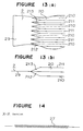
- FIG 13(a) there is shown a plan view of another example of the tapered leading portions.
- Figure 13(b) there is shown a vertical section of the portion shown in Figure 13(a).
- reference numeral 210 designates valleys of the corrugations 20.
- Reference numeral 211 designates mountains of the corrugations 20.
- Reference numeral 212 designates the valleys 210.
- Reference numeral 213 designates the tapered leading portions of the mountains 211.
- the tapered leading portions 212 and 213 are shaped to converge toward the flat side portions 29 and to have the leading edges angled, thereby clearly dividing the tapered leading portions of the mountains 211 and the valleys 210 from other portions.
- the boarders between the corrugations 20 and the flat side portions 29 it is usually possible to prevent the boarders between the corrugations 20 and the flat side portions 29 from being broken. Since the mountains and the valleys have the tops and the bottoms except for the tapered leading portions formed in an uncurved and flat manner, the corrugations and the flat surface portions which confront each other can be reliably jointed together, and the length of the jointed portions is extended to improve strength.
- the corrugations 20 and the boarders between the corrugations 20 and the flat side portions 29 are liable to be broken on production. There is danger of producing irregular wrinkles on the flat side portions 29 due to poor machining, thereby narrowing the passages formed at the flat side portions 29. This is because the sheet length required for the flat side portions 29 is shorter than that required for the corrugated portion or sections 20 in the partition 2 as seen from Figures 4, 9 and 10.
- the flat side portions 29 are formed with small corrugations to have the same sheet length as the corrugated portion or sections 20 as shown in Figure 14, the length of the flat side portion and that of the corrugated portion or sections in the longitudinal direction of the sheet can be equalized to avoid breakage on shaping the corrugated portion or sections, and to sufficiently ensure the passages at the flat side portions 29.
- the flat side portions 29 are formed in finer corrugations than the corrugated portion or sections 20 so as not to be tall.
- Required shaping can be easily carried out by pressing the sheet, using rollers with a finely corrugated surface at opposite ends of a corrugating roller for shaping the corrugated portion or sections, or using a corrugating roller integral with rollers with such a finely corrugated surface.
- the sheet gets liable to be broken.
- the beginning and the ending of the respective corrugated sections 20 are loaded in a pending direction because the partition 2 itself is zigzag bent.
- the vertical directions of the corrugations of the corrugated sections 20 and the flat side portions 29 can be identical at the beginning and the ending of the respective corrugated sections, allowing the corrugations to be formed without breaking the partition 2.
- the required gap between confronting corrugated portions 20, and the required gap between confronting corrugated surface portion 27 and flat surface portion 57 are held by the corrugations of the corrugated portion or sections 20.
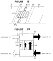
- the flat side portions 29 with the air inlets and outlets have no member for holding a required gap arranged thereon. Even if the flat side portions have the corrugations like the fourth embodiment, the corrugations are too small to hold the required gap.
- Figures 16-18 there are shown perspective views of structures to solve such a problem.
- reference numeral 36 designates side corrugated portions which are formed on the flat side portions 29 at the opposite side edges of the sheet, which has the corrugated direction directed to the same as that of the respective corrugated sections 20, and which has the corrugating direction arranged in parallel with the zigzag bent end surfaces.
- the height of the corrugations of the side corrugated portions 36 is the same as that of the corrugated sections 20.
- reference numeral 37 designates side corrugated portions which are formed on the flat side portions 29 at opposite side edges of the sheet, which have the corrugating direction arranged perpendicular to that of each corrugated section 20, and which have the corrugating direction arranged in parallel with the zigzag bent end surfaces.
- the height of the corrugations of the side corrugated portions 37 is the same as that of the corrugated sections 20.
- the passages which are formed by the corrugated sections 20 can confront the side surfaces of the corrugations of the side corrugated portions 37 at the opposite side edges of the partition 2 to smoothly direct air from the inlet to the corrugated sections 20 and from the corrugated sections 20 to the outlet due to straightening function, and to minimize resistance in the passages.
- confronting side corrugated portions 37 can be jointed to seal the opposed side edges of the partition 2 to improve airtightness as well as to improve durability of the side end seals 25 and 26.
- each side corrugated portion may be formed in a single corrugation 370 which has the corrugated direction arranged in the same direction as that of each corrugated section 20, and which has the corrugated direction arranged in parallel with the zigzag bent end surfaces as shown in Figure 18.
- the side corrugated portions may be formed in another shape.
- the heat exchanging element 1 has the air inlet and outlet placed 90° from the corrugated portion or sections 20.
- the respective passages in the respective layers formed by the corrugated portion or sections 20 have a substantially constant cross-sectional area though the respective passages are different from in terms of distance from the air inlet and outlet.
- the supplied air inlet 21 and the supplied air outlet 22 are arranged on the right side of the heat exchanging element 1 as shown in Figure 19, right-hand passages near to the air inlet and outlet have greater flow rates 38 while left-hand passages far from the air inlet and outlet have smaller flow rates 39.
- the discharged air inlet 23 and the discharged air outlet 24 are arranged on the left side of the heat exchanging element 1 in Figure 19.
- Left-hand passages near to the discharged air inlet and outlet have greater flow rates while right-hand passages far from the discharged air inlet and outlet have smaller flow rates.
- a main portion of the supplied air flows in the right-hand portion of the heat exchanging element, and main portion of the discharged air flows in the left-hand portion of the heat exchanging element, preventing heat exchange from being effectively carried out.
- reference numeral 40 designates pinched portion of corrugations 20 which are near to the gaps 28 and which are inwardly directed by zigzag bending.
- passages far from the air inlet and outlet have a greater cross-sectional area than passages near to the air inlet and outlet to increase flow rate therein.
- the passages nearer to the air inlet and outlet have greater flow rates.
- FIG. 22 there is shown a vertical section of an example of the heat exchanging element 1 which can solve this problem.
- reference numeral 41 designates a projection which is formed by pinching the top of each corrugation of the corrugated sections 20.
- Reference numeral 42 designates convexed portions and concave portions which are formed on the flat surface portions 57 at such locations that the respective tops of the corrugated sections 20 get in tough with the flat surface portions.
- the respective projections 41 can be engaged into and jointed to the corresponding concaved portions 42 of the flat surface portions to produce the heat exchanging element 1 in such a manner that the respective corrugations of the corrugated sections 20 are arranged at desired locations.
- jointing the corrugated sections 20 and the flat surface portions 57 can be carried out with use of identifications of the concaved portions 42 on production, and the jointing positions can be guided to proper locations to facilitate assembly.
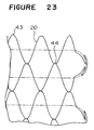
- FIG 23 there is shown a vertical section of a portion of another example of the partition 2 wherein the structure according to the seventh embodiment is applied to the structure according to the first embodiment.
- reference numeral 43 designates convexed portions or concave portions which are formed on the top of each corrugation of the corrugated portion 20 by pinching the top. Adjoining tops are alternately provided with the convexed portion and the concave portion.
- the partition 2 may be made of Japanese paper or other paper.
- the sheet includes metallic members like composite paper with metallic foil laminated thereon or composite paper with metallic wires or a metallic mesh sandwiched between two sheets
- the shaped corrugations can be held by the metallic nature.
- Use of such metallic members is superior in shaping the corrugations on the partition.
- the passages can be stably held to improve performance, and the metallic members can naturally improve heat transferring performance to minimize the heat exchanging element.
- aluminum, iron, copper, stainless steel and nickel are suitable in terms of metallic nature.
- metallic foil With respect to the shape of such metallic members, foil, an arrangement of thin wires or a mesh having a predetermined width can be adopted.
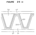
- metallic foil When metallic foil is used (see Figure 26(a)), heat transferring performance can be improved, and the corrugated form can be held to offer a good shape holding force in terms of plane.
- reference numeral 200 designates a paper sheet
- reference numeral 201 designates the metallic foil.
- the metallic members comprise thin wires (see Figure 26(b))
- the side portions of the respective corrugation i.e. portions in proximity to the boarders between the corrugations and the flat side portions have the thin wires passed along the longitudinal direction of the corrugations.
- reference numeral 200 designates the two paper sheets
- reference numerals 201b designate metallic wires.
- the metallic members can offer advantages which are respectively obtained by the foil and the thin wires.
- the foil, the thin wires and the mesh may be included in all the corrugations, or be arranged in only suitable portions in terms of shape or performance holding.
- the thickness of the foil, the extending direction of the wires, and the shape of the mesh can be properly determined depending on cases.
- the portions with the thin wires are not limited to the side portions of the corrugations.
- the metallic members have appropriate materials in terms of machinability, strength and cost.
- reference numeral 200 designates the two paper sheets
- reference numeral 201c designates an aluminum mesh.
- the heat exchanging element according to the present invention is applicable to e.g. a cassette type total heat exchanging unit as shown in Figure 24.
- the heat exchanging unit 1 according to one of the first to eighth embodiments can be arranged in a central portion of the total heat exchanging unit main body 101 to offer functions and advantages similar to the embodiments.
- the heat exchanging element 1 can be arranged at a central portion in an indoor side of the home heat exchanging unit main body 102 to offer functions and advantages similar to the embodiments.
- reference numeral 11 designates a ceiling with the cassette type total heat exchanging unit mounted therein.
- Reference numeral 12 designates a wall with the home heat exchanging unit mounted thereto.
Abstract
A heat exchanging element comprising a sheet (2), and a corrugated portion (20) formed on the sheet, characterized in that the sheet is zigzag bent in a layered structure to provide a first air flow passage (30) and a second air flow passage (31) which carry out heat exchange therebetween.
Description
- The present invention relates to a heat exchanging element which is used in a heat exchanger type ventilating device or an air conditioning unit.
- Working or living spaces in e.g. buildings for offices, apartments and town houses have been air conditioned in a wide range, increasing energy consumption for air conditioning. This creates a vital issue in that the energy consumption for air conditioning can be decreased to save energy. A heat exchanging element which carries out heat exchange between indoor air and outdoor air can save energy in an air conditioning unit by recovering the heat lost in ventilating a room. As an air conditioning and ventilating unit using such a heat exchanging element, there has been known a unit which is disclosed in e.g. JP-B-4719990. In order to make use of the working or living spaces more effectively, miniaturization of the ventilating device or the air conditioning unit has been highly required in recent years. Miniaturization of the heat exchanging element is an important issue.
- A conventional heat exchanging element is designed so that air supplied from outdoor is substantially perpendicular to air discharged from indoor as shown in Figure 27. In Figure 27,
reference numeral 1 designates the heat exchanging element,reference numeral 110 designates flat partitions which are made of a material having heat-conducting ability and moisture permeability, andreference numeral 111 designates spacers which have a corrugated form in section. Thepartitions 110 and thespacers 111 are alternately layered, and therespective spacers 111 are arranged to be turned through 90° with respect to their adjoined spacers.Reference numeral - The supplied air from outdoor is flowed in a direction indicated by shaded arrows, and discharged air from indoor is flowed in a direction indicated by unshaded arrows to carry out heat exchange, recovering heat. The heat exchange is carried out primarily through the
partitions 110, and the area which is effective in the heat exchange includes the area of the partitions and small portions of the spaces. The primary function of thespacers 111 is to provide required spaces betweenadjoining partitions 110. The reason why the small portions of thespacers 111 contribute to the heat exchange is that such portions of the spacers work as fins for the partitions. - It is known that use of an opposed flow heat exchanger where supplied air and discharged air flow in opposite directions can obtain higher heat exchanging efficiency without increasing the heat-conducting area in comparison with the conventional cross flow heat exchanger shown in Figure 27. Proposal for miniaturization of the heat exchanging element in such an opposed flow heat exchanger has been disclosed in e.g. JP-A-5822893. In Figure 28, there is shown a perspective view of a schematic structure of the heat exchanging element according to the proposal. In this Figure,
reference numeral 202 designates a partition,reference numeral 203 designates spacers on inlet sides, andreference numeral 204 designates spacers on outlet sides. - The
heat exchanging element 1 is constituted by thepartition 202 and thespacers partition 202 to carry out heat exchange. - In Figure 29, there is shown a view of the
partition 202 of theheat exchanging element 1 which is unfolded. In this conventional example, a sheet having a width A is used as thepartition 202. Thepartition 202 is an elongated article, and thepartition 202 has thespacers 203 on the respective inlet sides and thespacers 204 on the respective outlet sides bonded to opposed surfaces thereof. As shown in Figure 29, thepartition 202 has pairs of thespacers 203 and thespacers 204 alternately bonded to the opposed surfaces. The partitions has pairs offolds 205 arranged thereon so that the folds in each pair are apart from each other by a gap C between a portion thereof withspacers spacers partition 202 is zigzag bent at thefolds 205 to form theheat exchanging element 1 shown in Figure 28. - In Figure 30, it is shown what positions the
spacers partition 202 at thefolds 205. Because thepartition 202 is folded at predetermined intervals and layered, the pairs of thespacers spacers - In the
heat exchanging element 1 shown in Figure 28, thespacers partition 202, and the supplied air and the discharged air carries out little heat exchange through thespacers flat partition 202 and small portions of thespacers - Since the conventional heat exchanging elements have been constructed as stated earlier, the heat exchanging element shown in Figure 28 wherein the supplied air and the discharged air flow in the opposite directions and the partition is zigzag bent in the layered structure involves two main problems. One is that the supplied air and the discharged air carry out heat exchange through the flat partition but carry out no heat exchange through the corrugated spacers. The main purpose of the spacers is to ensure a required space for the partition to provide the air flow passages, which creates a problem in that only a small heat exchanging area is obtained in single use of the flat partition for heat exchange.
- The other is that the spacers for ensuring the required space are separable parts each other. It creates problems in that an increase in the number of parts required for the spacers raises cost, and that production is difficult because the spacers are individually and alternately bonded to the opposed surfaces of the partition.
- It is an object of the present invention to eliminate the problems, and to provide a heat exchanging element having good heat exchanging efficiency between supplied air and discharged air. It is another object of the present invention to provide a heat exchanging element which requires a small number of parts, which is easily fabricated, and which can ensure to provide spaces required for forming air flow passages. The present invention provides a heat exchanging element which comprising a sheet and a corrugated portion formed on the sheet, wherein the sheet is zigzag bent in a layered structure to provide a first air flow passage and a second air flow passage which carry out heat exchange therebetween.
- The corrugated portion may be continuously formed on the sheet.
- The sheet may comprise corrugated surface portions and flat surface portions, each corrugated surface portion having the corrugated portion formed thereon, the corrugated surface portions and the flat surface portions being alternately layered.
- The corrugated portion may have corrugations formed at predetermined intervals.
- Bend end surfaces of the sheet which is zigzag bent may be in parallel with the passages formed at the corrugated portion.
- The corrugated portion may have opposed leading edges of the corrugations tapered.
- The sheet may have a surface in parallel with a corrugating direction of the corrugated portion formed with smaller corrugations than the corrugated portion.
- The number of the smaller corrugations may be odd times that of the corrugations of the corrugated portion.
- The sheet may have a side edge formed with side edge corrugations to provide spaces for the passages.
- The side edge corrugations may have a corrugating direction in parallel with that of the corrugated portion.
- The side edge corrugations may have a corrugating direction perpendicular to that of the corrugated portion.
- The corrugated portion may have corrugations formed so that the first and second passages formed by the corrugated portion can have air flows equalized therein.
- The corrugated portion may have the respective corrugations pinched to be crushed by a predetermined length from the top of the respective corrugations over the entire length of the passages.
- The corrugated portion may have the respective corrugations formed so that one of adjoining passages has a longer pinched portions than the other passage.
- The corrugated portion, and portions of the sheet which get in touch with the corrugations of the corrugated portion in the layered structure have convexed portions and concave portions formed thereon so as to be engaged each other.
- The sheet may have metal members included therein.
- The metal members may be one of aluminum, iron, copper, stainless steel and nickel.
- The metal members may be formed in one of a predetermined width of foil, thin wire or mesh.
- The invention will now be described by way of example and with reference to the accompanying drawings in which:
- Figure 1 is a schematic perspective view showing the heat exchanging element according to a first embodiment of the present invention;
- Figure 2 is a perspective view showing a part of the partition shown in Figure 1, which has been unfolded;
- Figure 3 is a vertical sectional view taken along the line III-III of Figure 1;
- Figure 4 is a vertical sectional view taken along the line IV-IV of Figure 1;
- Figure 5 is a perspective view of the section at the line III-III of Figure 1;
- Figure 6 is a cross-sectional view showing a ceiling mounted and concealed type total heat exchanging unit with the heat exchanging element according to the invention incorporated thereinto;
- Figure 7 is a schematic perspective view showing the heat exchanging element according to a second embodiment of the present invention;
- Figure 8 is a perspective view of a portion of the partition shown in Figure 7, which has been unfolded;
- Figure 9 is a vertical section taken along the line IX-IX of Figure 8;
- Figure 10 is a vertical section taken along the line X-X of Figure 8;
- Figure 11 is a vertical section of Figure 7 taken along the line IX-IX of Figure 8;
- Figure 12 is a vertical section of Figure 7 taken along the line X-X of Figure 8;
- Figures 13(a) and (b) are a plan view and a vertical section, respectively, showing the corrugated portion of the heat exchanging element according to a third embodiment of the present invention;
- Figure 14 is a vertical section of a portion of the heat exchanging element according to a fourth embodiment of the present invention, corresponding to the section taken along the line X-X of Figure 8;
- Figure 15 is comparative views of the fourth embodiment, corresponding to the sections taken along the line X-X and the line IX-IX of Figure 8;
- Figure 16 is a perspective view showing a portion of the partition according to a fifth embodiment of the present invention, which has been unfolded;
- Figure 17 is a perspective view showing a portion of the unfolded partition of another example according to the fifth embodiment;
- Figure 18 is a perspective view showing a portion of the unfolded partition of another example according to the fifth embodiment;
- Figure 19 is a schematic view showing flow distribution when the passages formed by the corrugated portion have the same shape;
- Figure 20 is a vertical section of a portion of the heat exchanging element according to a sixth embodiment of the present invention;
- Figure 21 is a schematic view showing the flow distribution in the heat exchanging element according to the sixth embodiment;
- Figure 22 is a vertical section showing a portion of an example of the heat exchanging element according to a seventh embodiment of the present invention;
- Figure 23 is a vertical section showing a portion of another example of the heat exchanging element according to the seventh embodiment of the present invention;
- Figure 24 is a vertical section showing a cassette type total heat exchanging unit with the heat exchanging element according to the invention incorporated thereinto;
- Figure 25 is a cross-sectional view showing a home heat exchanging unit with the heat exchanging element of the invention incorporated thereinto;
- Figure 26(a) is a vertical section showing a portion of composite paper with metallic foil laminated thereon;
- Figure 26(b) is a vertical section showing a portion of composite paper with metallic wires sandwiched between two sheets;
- Figure 26(c) is a vertical section showing a portion of composite paper with a metallic mesh sandwiched between two sheets;
- Figure 27 is a perspective view showing a conventional heat exchanging element;
- Figure 28 is a perspective view showing another conventional heat exchanging element;
- Figure 29 is a perspective view showing a portion of the heat exchanging element shown in Figure 27, which has been unfolded; and
- Figure 30 is a schematic view showing how the unfolded heat exchanging element as shown in Figure 28 is bent.
- In Figure 1, there is shown a schematic perspective view of the heat exchanging element according to a first embodiment of the present invention. In this figure, parts identical or corresponding to those in the prior art are designated with the same reference numerals, and explanation of such parts will be omitted. In this figure,
reference numeral 2 designates a partition which is formed by zigzag bending a single sheet at intervals of a suitable length so as to provide a layered structure.Reference numeral 20 designates a corrugated portion which is provided on thepartition 2, which is shaped by corrugating opposed central surfaces of the sheet, and which has both central surfaces provided with passages extended from one side edge to the other side edge. - The
partition 2 is zigzag bent to alternately arrange open ends and closed ends at both end portions of theheat exchange element 1.Reference numeral 21 designates a supplied air inlet which is provided in an open portion at a front side on the figure. The open portion is defined by thecorrugated portion 20 at the open ends at one of the side portions of theheat exchanging element 1.Reference numeral 22 designates a supplied air outlet which is provided in an open portion at a rear side on the figure. The rear open portion is defined by thecorrugated portion 20 at the open ends at the other side portion of the heat exchanging element.Reference numeral 23 designates a discharged air inlet which is provided in an open portion at a rear side on the figure. The opened portion with the discharged air inlet is defined by thecorrugated portion 20 at the open ends at the other side portion of the heat exchanging element.Reference numeral 24 designates a discharged air outlet which is provided in an open portion at a front side on the figure. The open portion with the discharged air outlet is defined by thecorrugated portion 20 at the open ends at the one side portion of the heat exchanging element.Reference numerals - Such arrangement allows supplied air passages as first air passages and discharged air passages as second air passages to be isolated by the
partition 2, and the respective passages to ensure and obtain required gaps by only thepartition 2 without help of spacers. Although a sine wave, a trapezoidal wave or a rectangular wave can be adopted as the wave form of thecorrugated portion 20, the wave form of the corrugated portion is not limited to these wave forms. The point is that when thepartition 2 is zigzag bent in the layered structure, the corrugated portion works as spacers to ensure the first air passages and the second air passages. In this embodiment, the corrugated portion is shaped in a wave form of corrugations which is used in e.g. corrugated paper and is good at strength. - In Figure 2, there is shown a perspective view of a portion of the
partition 2 constituting theheat exchanging element 1, which has been unfolded in a flat manner. In this figure, thepartition 2 has the corrugatedportion 20 continuously formed at a central portion of the sheet. Thecorrugated portion 20 is formed in such a manner that a flat sheet, such as Japanese paper and converted paper, which is commonly used as a heat exchanging element partition, has a central portion pressed to provide continuous corrugations without cutting the sheet into short pieces, thereby providing equal corrugations on both surfaces of the sheet.Reference numeral 29 designates flat side portions which are left flat on both sides of the sheet. Boarders between thecorrugated portion 20 and theflat side portions 29 are formed so that leading portions of the corrugations in proximity to the flat side portions are tapered in order to prevent the sheet from being broken on shaping. If the sheet is too tough to be broken, it is not necessary to taper the leading portion of the corrugations. - The
partition 2 according to this embodiment is formed so as to have an equal structure in its entirety. Since the partition is bendable at any locations, the sheet can be zigzag bent at any locations. As a result, forming thecorrugated portion 20 can be successively carried out on the sheet. Whichever portion of the sheet is cut at to start zigzag bending, theheat exchanging element 1 can be fabricated to extremely facilitate manufacturing and working. The distance between adjoining corrugations is determined so that when the sheet is zigzag bent, the tops of confronting corrugations of thecorrugated portion 20 contact with each other. When the sheet has been layered as stated, the tops of the confronting corrugations of thecorrugated portion 20 are jointed together to provide the passages between the corrugations of the jointedcorrugated portion 20. - In Figure 3, there is shown a vertical section of the
heat exchanging element 1 of Figure 1, taken along the line III-III. As shown in Figure 3, thecorrugated portion 20 is formed so that the corrugations are repeated upwardly and downwardly on both surfaces with respect to the sheet plane, and that the tops of the confronting corrugations are jointed to alternately upwardly and downwardly provide the supplied air passages 30 (indicated by symbols "X") and the discharged air passages 31 (indicated by symbols "○") between the adjoining corrugations. The sheet has side portions at the front and rear sides in Figure 1 formed with theflat portions 29, and the shape of the flat portions is flat as shown in Figure 4 which is a vertical section taken along the line IV-IV of Figure 1. In Figure 5, there is shown a perspective view of the section of theheat exchanging element 1 taken along the line III-III of Figure 1. Portions of the zigzag bentcorrugated portions 20 which are formed with folds have the passages therein crushed to be finally bonded to the sheet, increasing air tightness. - Because the
heat exchanging element 1 is formed by zigzag bending thepartition 2, each layer has one end closed. The side edges of the sheet are closed by the side end seals 25 and 26. Each layer has only an end portion remote from the zigzag bend fold worked as the open end. The heat exchanging element has the respective open ends and the respective zigzag bend folds alternately arranged in the vertical direction. The passages formed by thecorrugated portion 20 are the ones that the respective passages have both ends communicated with respective open end portions through bothflat portions 29. As shown in Figure 1, the supplied air passages are formed to extend from the suppliedair inlet 21 to the suppliedair outlet 22 through thecorrugated portion 20, and the discharged air passages are formed to extend from the dischargedair inlet 23 to the dischargedair outlet 24 through thecorrugated portion 20. - In Figure 6, there is shown a cross-sectional of a ceiling mounted and concealed type total heat exchanging unit with a heat exchanging element of Figure 1 incorporated thereinto. In this figure,
reference numeral 100 designates a ceiling mounted and concealed type total heat exchanging unit main body.Reference numeral 1 designates the heat exchanging element which is incorporated into a central portion of the total heat exchanging unit.Reference numeral 5 designates an air supplying fan which is constituted by a centrifugal fan, and which has an inlet communicated with the suppliedair outlet 22 of theheat exchanging element 1.Reference numeral 6 designates an air discharging fan which is constituted by a centrifugal fan, and which has an inlet communicated with the dischargedair outlet 24 of theheat exchanging element 1.Reference numeral 7 designates a supplied air inlet port which is connected to outdoors, and which communicates with the suppliedair inlet 21 of theheat exchanging element 1.Reference numeral 8 designates a supplied air outlet port which communicates with an outlet of theair supplying fan 5, and which is connected to indoors. -
Reference numeral 9 designates a discharged air inlet port which is connected to indoors, and which communicates with the dischargedair inlet 23 of theheat exchanging element 1.Reference numeral 10 designates a discharged air outlet port which communicates with an outlet of theair discharging fan 6, and which is connected to outdoors.Reference numeral 3 designates a supplied air flow, andreference numeral 4 designates a discharge air flow. Although not shown, the suppliedair inlet port 7, the suppliedair outlet port 8, the dischargedair inlet port 9 and the dischargedair outlet port 10 are connected to e.g. ducts to properly lead indoors and outdoors through duct piping. - In the total heat exchanging unit and the
heat exchanging element 1 therein thus constructed, supplied air from outdoors flows from the suppliedair inlet port 7 into the suppliedair inlet 21 of theheat exchanging element 1, passes through thecorrugated portion 20 and flows out of the suppliedair outlet 22 to indoors through the suppliedair outlet port 8. Discharged air from indoors flows from the dischargedair inlet port 9 into the dischargedair inlet 23 of theheat exchanging element 1, passes through thecorrugated portion 20 and flows out of the dischargedair outlet 24 to outdoors through the dischargedair outlet port 10. At that time, the supplied air and the discharged air flow in opposite directions since the suppliedair passages 30 and the dischargedair passages 31 in theheat exchanging element 1 are divided by thepartition 2 so as to be alternately arranged as clearly seen from the structure of the heat exchanging element shown in Figures 3 and 5. - When the supplied air and the discharged air flow in the
heat exchanging element 1, the supplied air and the discharged air carry out heat exchange through thepartition 2. According to the arrangement of the present invention, thepartition 2 can be corrugated to increase a heat exchanging area per unit volume in comparison with the conventional flat partition, improving heat exchanging efficiency. Since the heat exchanging element is layered by using only the partition, machining and assembling are easy. The corrugated portion which works as spacers can be also contributed to heat exchange to go no waste. When the corrugated portion is continuously formed like this embodiment, cutting can be made at any locations. No need for intermittent pressing can facilitate production and decrease cost. - Since the zigzag bent end surfaces and the ridges of the corrugated portion extend in parallel, the side edges of the passages formed by the corrugated portion are sealed by folds in a seamless manner to improve airtightness. When opposite sides of the end portions which have the open ends and the folds alternately formed by zigzag bending work as the air inlets and the air outlets, and the supplied air and the discharged air turn at 90° to pass through the corrugated portion like this embodiment, the opposite sides of the end portions with the air inlets and the air outlets have no need for special sealing between the different air flow layers, facilitating production.
- In Figure 7, there is shown a schematic perspective view of the heat exchanging element according to another embodiment of the present invention. In this figure, parts identical or corresponding to those in the first embodiment are designated with the same reference numerals, and explanation of such parts will be omitted. In this figure,
reference numeral 2 designates a partition which is formed by zigzag bending a single sheet at intervals of a suitable length so as to provide a layered structure.Reference numeral 20 designates a corrugated portion which is provided on thepartition 2. Thecorrugated portion 20 is shaped by corrugating opposed central surfaces of the sheet so as to provide corrugated sections in a longitudinal direction except for folds which are formed when the sheet is zigzag bent. Thepartition 2 is also provided withflat surface sections 57 between corrugated sections. Thecorrugated sections 20 and theflat surface portions 57 are alternately layered to ensure required gaps, having opposite surfaces of the sheet provided with passages extended from one side edge to the other side edge of the sheet. - Such arrangement allows the supplied air passages as the first air passages and the discharged air passages as the second air passages to be isolated by the
partition 2, and the respective passages to be ensured only by thepartition 2 without using spacers. Although the sine wave, a trapezoidal wave or a rectangular wave can be adopted as the wave form of thecorrugated sections 20, the wave form of the corrugated sections is not limited to these wave forms. The point is that when thepartition 2 is zigzag bent in the layered structure, the corrugated sections work as the spacers to ensure the first air passages and the second air passages. In this embodiment, the corrugated sections are shaped in a wave form of corrugations which is used in e.g. corrugated paper and is good at strength. - In Figure 8, there is shown a perspective view of a portion of the
partition 2 constituting theheat exchanging element 1, which has been unfolded in a flat manner. In this figure, thepartition 2 has a central portion of the sheet formed with thecorrugated sections 20 with a certain number of continuous corrugations at intervals of a certain length. Thecorrugated sections 20 are formed in such a manner that a flat sheet, such as Japanese paper and converted paper, which is commonly used as a heat exchanging element partition, has a central portion intermittently pressed to provide the discontinuous corrugated sections without cutting the sheet into short pieces, thereby providing similar corrugations on both surfaces of the sheet.Reference numeral 29 designates the flat side portions which are left flat on both sides of the sheet. Boarders between thecorrugated sections 20 and theflat side portions 29 may be formed so that leading portions of the corrugations in proximity to the flat side portions are tapered in order to prevent the sheet from being broken on shaping. -
Reference numeral 57 designates the flat surface portions which are uncorrugated on the sheet, which has the same length as thecorrugated sections 20, and which have a length equal to that of flat surface portions except for the folds which are formed when the sheet is zigzag bent.Reference numeral 28 designates a gap which works as a fold when the sheet is bent. The sheet shown in Figure 8 is formed so that thecorrugated surface portions 27 withflat side portions 29 and acorrugated section 20, and theflat surface portions 57 are alternately arranged interposing eachgap 28 therebetween so as to provide a cyclic chain. In order to prepare thepartition 2, the sheet may be cut into pieces of a suitable length before being layered, or be cut after being layered. - In the
partition 2 according to this embodiment, thecorrugated surface portions 27 and theflat surface portions 57 are alternately layered by zigzag bending the partition at eachgap 28, and the tops of the respective corrugations of thecorrugated sections 20 are jointed to theflat surface portions 57 which the tops get in touch with when the corrugated surface portions and the flat surface portions are layered. Such arrangement can joint the tops of the respective corrugations and the flat surfaces without jointing the confronting tops of the corrugations like the first embodiment. As a result, jointing the corrugated sections does not require high accuracy unlike the first embodiment, facilitating assembly. Since the second embodiment have no need for spacers like the first embodiment, manufacturing and machining can be carried out in an extremely easy manner. - In Figure 9, there is shown a vertical section of a portion of the
partition 2 shown in Figure 8, taken along the line IX-IX. As shown in Figure 9, the respectivecorrugated sections 20 are formed so that the corrugations are repeated upwardly and downwardly on both surfaces with respect to the sheet plane. The tops of the respective corrugations are jointed to theflat surface portions 57 to alternately arrange the suppliedair passages 30 and the dischargedair passages 31 between the corrugations as shown in Figure 11 and to partition the respective corrugations by theflat surface portions 57. In Figure 10, there is shown a vertical section of a portion of thepartition 2 shown in Figure 8, taken along the line X-X. The portion shown in Figure 10 correspond to theflat side portions 29 at the front side and at the rear side in Figure 7, and is shaped to be flat as shown in Figure 12. - Because the
heat exchanging element 1 is formed by zigzag bending thepartition 2, each layer has one end closed. The side edges of the sheet are closed by the side end seals 25 and 26. Each layer has only an end portion remote from the zigzag bent fold worked as the open end. The heat exchanging element has the respective open ends and the respective zigzag bent folds alternately arranged in the vertical direction. The passages formed by thecorrugated sections 20 are the ones that the respective passages have both ends communicated with respective open end portions through bothflat portions 29. As shown in Figure 7, the supplied air passages are formed to extend from the suppliedair inlet 21 to the suppliedair outlet 22 through thecorrugated sections 20, and the discharged air passages are formed to extend from the dischargedair inlet 23 to the discharged air outlet through thecorrugated sections 20. - The second embodiment is identical to the first embodiment except for the arrangement as just stated. The heat exchanging element according to the second embodiment has the same application as the one according to the first embodiment. For example, the
heat exchanging element 1 in accordance with the second embodiment can be incorporated into the ceiling mounted and concealed type total heat exchanging unit shown in Figure 6. The total heat exchanging unit with theheat exchanging element 1 of the second embodiment can carry out heat exchange like the one of the first embodiment. - According to the arrangement of the present invention, the
partition 2 can be corrugated to increase a heat exchanging area in comparison with the conventional flat partitions, thereby improving heat exchanging efficiency. Since the heat exchanging element is layered by using only the partition, machining and assembly are easy. In addition, the corrugated sections which work as spacers is also contributed to heat exchange to go no waste. In accordance with this embodiment, the corrugated surface portions and the flat surface portions can be alternately layered to joint the tops of the corrugations and the flat surface portions without need for high accuracy. As a result, production and assembly are easy to save cost. - In the first and second embodiments, when a material with poor ductility, such as Japanese paper or converted paper, is used to prepare the
partition 2 with thecorrugated sections 20, there is danger of occurring a break in thecorrugations 20 or in the boarders between thecorrugations 20 and theflat side portions 29. In order to avoid the break, the respective corrugations are shaped to have the leading portions in proximity to the flat side portions tapered. - In Figure 13(a), there is shown a plan view of another example of the tapered leading portions. In Figure 13(b), there is shown a vertical section of the portion shown in Figure 13(a). In these figures,
reference numeral 210 designates valleys of thecorrugations 20.Reference numeral 211 designates mountains of thecorrugations 20.Reference numeral 212 designates thevalleys 210.Reference numeral 213 designates the tapered leading portions of themountains 211. - When the
corrugations 20 are formed in such a shape, the tapered leadingportions flat side portions 29 and to have the leading edges angled, thereby clearly dividing the tapered leading portions of themountains 211 and thevalleys 210 from other portions. As a result, it is usually possible to prevent the boarders between thecorrugations 20 and theflat side portions 29 from being broken. Since the mountains and the valleys have the tops and the bottoms except for the tapered leading portions formed in an uncurved and flat manner, the corrugations and the flat surface portions which confront each other can be reliably jointed together, and the length of the jointed portions is extended to improve strength. - In the first and second embodiments, when a material with poor ductility, such as Japanese paper or converted paper, is used to prepare the
partition 2 with thecorrugations 20, thecorrugations 20 and the boarders between thecorrugations 20 and theflat side portions 29 are liable to be broken on production. There is danger of producing irregular wrinkles on theflat side portions 29 due to poor machining, thereby narrowing the passages formed at theflat side portions 29. This is because the sheet length required for theflat side portions 29 is shorter than that required for the corrugated portion orsections 20 in thepartition 2 as seen from Figures 4, 9 and 10. - When the
flat side portions 29 are formed with small corrugations to have the same sheet length as the corrugated portion orsections 20 as shown in Figure 14, the length of the flat side portion and that of the corrugated portion or sections in the longitudinal direction of the sheet can be equalized to avoid breakage on shaping the corrugated portion or sections, and to sufficiently ensure the passages at theflat side portions 29. In the example shown in Figure 14, theflat side portions 29 are formed in finer corrugations than the corrugated portion orsections 20 so as not to be tall. Required shaping can be easily carried out by pressing the sheet, using rollers with a finely corrugated surface at opposite ends of a corrugating roller for shaping the corrugated portion or sections, or using a corrugating roller integral with rollers with such a finely corrugated surface. - If the vertical directions of the corrugations of the corrugated portion or sections and the flat side portions are opposite at the boarder between the corrugated portion or
sections 20 and theflat side portions 29, the sheet gets liable to be broken. In particular, the beginning and the ending of the respectivecorrugated sections 20 are loaded in a pending direction because thepartition 2 itself is zigzag bent. In order to avoid such loading, the distance LB between adjoining tops of the bigger corrugations of thecorrugated sections 20 and the distance LA between adjoining tops of the smaller corrugations have a relation which satisfies an equality of
corrugated sections 20 and theflat side portions 29 can be identical at the beginning and the ending of the respective corrugated sections, allowing the corrugations to be formed without breaking thepartition 2. - In the first to fourth embodiments, the required gap between confronting
corrugated portions 20, and the required gap between confrontingcorrugated surface portion 27 andflat surface portion 57 are held by the corrugations of the corrugated portion orsections 20. However, theflat side portions 29 with the air inlets and outlets have no member for holding a required gap arranged thereon. Even if the flat side portions have the corrugations like the fourth embodiment, the corrugations are too small to hold the required gap. In Figures 16-18, there are shown perspective views of structures to solve such a problem. - In Figure 16,
reference numeral 36 designates side corrugated portions which are formed on theflat side portions 29 at the opposite side edges of the sheet, which has the corrugated direction directed to the same as that of the respectivecorrugated sections 20, and which has the corrugating direction arranged in parallel with the zigzag bent end surfaces. The height of the corrugations of the side corrugatedportions 36 is the same as that of thecorrugated sections 20. By such arrangement, the gap required between confronting side edges of thepartition 2 can be held by the corrugations having the same direction as each corrugated section to provide the required gap with good strength. - In Figure 17, there is shown another example. In Figure 17,
reference numeral 37 designates side corrugated portions which are formed on theflat side portions 29 at opposite side edges of the sheet, which have the corrugating direction arranged perpendicular to that of eachcorrugated section 20, and which have the corrugating direction arranged in parallel with the zigzag bent end surfaces. The height of the corrugations of the side corrugatedportions 37 is the same as that of thecorrugated sections 20. By such arrangement, the passages which are formed by thecorrugated sections 20 can confront the side surfaces of the corrugations of the side corrugatedportions 37 at the opposite side edges of thepartition 2 to smoothly direct air from the inlet to thecorrugated sections 20 and from thecorrugated sections 20 to the outlet due to straightening function, and to minimize resistance in the passages. - In addition, confronting side corrugated
portions 37 can be jointed to seal the opposed side edges of thepartition 2 to improve airtightness as well as to improve durability of the side end seals 25 and 26. - The shape of the side corrugated portions is not limited to the one just stated. For example, each side corrugated portion may be formed in a
single corrugation 370 which has the corrugated direction arranged in the same direction as that of eachcorrugated section 20, and which has the corrugated direction arranged in parallel with the zigzag bent end surfaces as shown in Figure 18. The side corrugated portions may be formed in another shape. - In the first to fourth embodiments, the
heat exchanging element 1 has the air inlet and outlet placed 90° from the corrugated portion orsections 20. The respective passages in the respective layers formed by the corrugated portion orsections 20 have a substantially constant cross-sectional area though the respective passages are different from in terms of distance from the air inlet and outlet. Specifically, when the suppliedair inlet 21 and the suppliedair outlet 22 are arranged on the right side of theheat exchanging element 1 as shown in Figure 19, right-hand passages near to the air inlet and outlet havegreater flow rates 38 while left-hand passages far from the air inlet and outlet have smaller flow rates 39. - In this case, the discharged
air inlet 23 and the dischargedair outlet 24 are arranged on the left side of theheat exchanging element 1 in Figure 19. Left-hand passages near to the discharged air inlet and outlet have greater flow rates while right-hand passages far from the discharged air inlet and outlet have smaller flow rates. As a result, a main portion of the supplied air flows in the right-hand portion of the heat exchanging element, and main portion of the discharged air flows in the left-hand portion of the heat exchanging element, preventing heat exchange from being effectively carried out. - In Figure 20, there is shown a vertical section of the
partition 2 to explain the structure to solve this problem. In this figure,reference numeral 40 designates pinched portion ofcorrugations 20 which are near to thegaps 28 and which are inwardly directed by zigzag bending. - By such arrangement, passages far from the air inlet and outlet have a greater cross-sectional area than passages near to the air inlet and outlet to increase flow rate therein. In the first to fourth embodiments, the passages nearer to the air inlet and outlet have greater flow rates. When the length of the pinched portion is gradually increased as the corrugations approach in each zigzag bent end surfaces as shown in Figure 20, the flow rates in the respective passages can be equalized as shown in Figure 21 to improve heat exchanging efficiency in the
heat exchanging element 1 as a whole. - Although in the second embodiment the tops of the respective corrugations of the
corrugated sections 20 are jointed to theflat surface portions 57 when thepartition 2 is zigzag bent, there is a possibility that the jointing positions are neither equally distributed in theheat exchanging element 1 as a whole nor occupy desired locations to cause insufficient jointing, leading to leakage or damage. There is also a possibility that the resistance in the passages change to lower heat exchanging efficiency. In Figure 22, there is shown a vertical section of an example of theheat exchanging element 1 which can solve this problem. In this figure,reference numeral 41 designates a projection which is formed by pinching the top of each corrugation of thecorrugated sections 20.Reference numeral 42 designates convexed portions and concave portions which are formed on theflat surface portions 57 at such locations that the respective tops of thecorrugated sections 20 get in tough with the flat surface portions. - By such arrangement, when the
partition 2 is zigzag bent in a layered structure, therespective projections 41 can be engaged into and jointed to the correspondingconcaved portions 42 of the flat surface portions to produce theheat exchanging element 1 in such a manner that the respective corrugations of thecorrugated sections 20 are arranged at desired locations. As a result, it is possible to minimize leakage and avoid breakage. In addition, jointing thecorrugated sections 20 and theflat surface portions 57 can be carried out with use of identifications of theconcaved portions 42 on production, and the jointing positions can be guided to proper locations to facilitate assembly. - In Figure 23, there is shown a vertical section of a portion of another example of the
partition 2 wherein the structure according to the seventh embodiment is applied to the structure according to the first embodiment. In this figure,reference numeral 43 designates convexed portions or concave portions which are formed on the top of each corrugation of thecorrugated portion 20 by pinching the top. Adjoining tops are alternately provided with the convexed portion and the concave portion. When the partition is zigzag bent in a layered structure, corrugations which joint together has the convexed portion and the concaved portion engaged each other. - By such arrangement, an advantage similar to the seventh embodiment can be obtained.
- In the embodiments stated earlier, the
partition 2 may be made of Japanese paper or other paper. When the sheet includes metallic members like composite paper with metallic foil laminated thereon or composite paper with metallic wires or a metallic mesh sandwiched between two sheets, the shaped corrugations can be held by the metallic nature. Use of such metallic members is superior in shaping the corrugations on the partition. The passages can be stably held to improve performance, and the metallic members can naturally improve heat transferring performance to minimize the heat exchanging element. In order to obtain these advantages, aluminum, iron, copper, stainless steel and nickel are suitable in terms of metallic nature. - With respect to the shape of such metallic members, foil, an arrangement of thin wires or a mesh having a predetermined width can be adopted. When metallic foil is used (see Figure 26(a)), heat transferring performance can be improved, and the corrugated form can be held to offer a good shape holding force in terms of plane. In Figure 26(a),
reference numeral 200 designates a paper sheet, andreference numeral 201 designates the metallic foil. When the metallic members comprise thin wires (see Figure 26(b)), the side portions of the respective corrugation i.e. portions in proximity to the boarders between the corrugations and the flat side portions have the thin wires passed along the longitudinal direction of the corrugations. In such arrangement, the area which is occupied by the metallic members at the corrugations is minimized to sufficiently ensure an are of the partition which works for humid exchange. In addition, a high holding force can be obtained for a long period of time to prevent the corrugations from collapsing at the boarders between the corrugations and the flat side portions. The heat exchanging element becomes lighter by a decrease in portions with the metallic members. In Figure 26(b),reference numeral 200 designates the two paper sheets, andreference numerals 201b designate metallic wires. - When the metallic members have a mesh structure (see Figure 26(c)), the metallic members can offer advantages which are respectively obtained by the foil and the thin wires. The foil, the thin wires and the mesh may be included in all the corrugations, or be arranged in only suitable portions in terms of shape or performance holding. The thickness of the foil, the extending direction of the wires, and the shape of the mesh can be properly determined depending on cases. When the thin wires are used, the portions with the thin wires are not limited to the side portions of the corrugations. The metallic members have appropriate materials in terms of machinability, strength and cost. In Figure 26(c),
reference numeral 200 designates the two paper sheets, and reference numeral 201c designates an aluminum mesh. - Although the ceiling mounted and concealed type total heat exchanging unit as shown in Figure 6 has been referred to the explanation on the embodiments, the heat exchanging element according to the present invention is applicable to e.g. a cassette type total heat exchanging unit as shown in Figure 24. In that case, the
heat exchanging unit 1 according to one of the first to eighth embodiments can be arranged in a central portion of the total heat exchanging unitmain body 101 to offer functions and advantages similar to the embodiments. With regard to a home heat exchanging unit as shown in Figure 25 as well, theheat exchanging element 1 can be arranged at a central portion in an indoor side of the home heat exchanging unitmain body 102 to offer functions and advantages similar to the embodiments. In Figures 24 and 25,reference numeral 11 designates a ceiling with the cassette type total heat exchanging unit mounted therein.Reference numeral 12 designates a wall with the home heat exchanging unit mounted thereto.
Claims (10)
- A heat exchanging element comprising:a sheet (2); anda corrugated portion (20) formed on the sheet;
characterized in that the sheet is zigzag bent in a layered structure to provide a first air flow passage (30) and a second air flow passage (31) which carry out heat exchange therebetween. - A heat exchanging element according to Claim 1, characterized in that the corrugated portion (20) is continuously formed on the sheet (2).
- A heat exchanging element according to Claim 1, characterized in that the sheet (2) comprises corrugated surface portions (27) and flat surface portions (57), each corrugated surface portion having the corrugated portion (20) formed thereon, the corrugated surface portions and the flat surface portions being alternately layered.
- A heat exchanging element according to Claim 1, characterized in that the corrugated portion (20) has corrugations formed at predetermined intervals.
- A heat exchanging element according to any one of Claims 1 to 4, characterized in that bent end surfaces of the sheet (2) which is zigzag bent are in parallel with the passages (30,31) formed at the corrugated portion (20).
- A heat exchanging element according to any one of Claims 1 to 4, characterized in that the sheet (2) has a surface (29) in parallel with a corrugating direction of the corrugated portion (20) formed with smaller corrugations than the corrugated portion.
- A heat exchanging element according to Claim 6, characterized in that the number of the smaller corrugations is odd times that of the corrugations of the corrugated portion (20).
- A heat exchanging element according to any one of Claims 1 to 4, characterized in that the corrugated portion (20) has corrugations formed so that the first and second passages (30,31) formed by the corrugated portion can have air flows equalized therein.
- A heat exchanging element according to Claim 8, characterized in that the corrugated portion (20) has the respective corrugations pinched to be crushed by a predetermined length from the top of the respective corrugations over the entire length of the passages (30,31).
- A heat exchanging element according to Claim 9, characterized in that the corrugated portion (20) has the respective corrugations formed so that one of adjoining passages (30,31) has a longer pinched portions (40) than the other passage.
Applications Claiming Priority (2)
| Application Number | Priority Date | Filing Date | Title |
|---|---|---|---|
| JP311028/95 | 1995-11-29 | ||
| JP31102895A JP3612826B2 (en) | 1995-11-29 | 1995-11-29 | Heat exchange element |
Publications (2)
| Publication Number | Publication Date |
|---|---|
| EP0777094A2 true EP0777094A2 (en) | 1997-06-04 |
| EP0777094A3 EP0777094A3 (en) | 1998-11-25 |
Family
ID=18012248
Family Applications (1)
| Application Number | Title | Priority Date | Filing Date |
|---|---|---|---|
| EP96118887A Withdrawn EP0777094A3 (en) | 1995-11-29 | 1996-11-25 | Heat exchanging element |
Country Status (3)
| Country | Link |
|---|---|
| EP (1) | EP0777094A3 (en) |
| JP (1) | JP3612826B2 (en) |
| CA (1) | CA2190793A1 (en) |
Cited By (17)
| Publication number | Priority date | Publication date | Assignee | Title |
|---|---|---|---|---|
| EP0787953A3 (en) * | 1996-02-02 | 1998-08-05 | Schako Metallwarenfabrik Ferdinand Schad Kg | Air-conditioner with energy recovery |
| WO1999013283A1 (en) * | 1997-09-10 | 1999-03-18 | Baxi Air Management Limited | Heat exchanger |
| EP0829692A3 (en) * | 1996-09-12 | 1999-07-21 | Mitsubishi Denki Kabushiki Kaisha | Heat exchanger and method of manufacturing a heat exchanging member of a heat exchanger |
| WO2000017591A1 (en) * | 1998-09-21 | 2000-03-30 | Andrzej Sokulski | Plate-type heat exchanger |
| EP1269098A1 (en) * | 2000-03-14 | 2003-01-02 | Air-Change Pty Limited | Heat exchanger |
| WO2004040219A1 (en) * | 2002-10-31 | 2004-05-13 | Oxycell Holding B.V. | Heat exchanger and method of manufacture thereof |
| EP1538398A2 (en) * | 2003-12-05 | 2005-06-08 | 2H KUNSTSTOFF GmbH | Contact body, in particular for an evaporative humidifier, and method to produce a contact body |
| WO2006008184A1 (en) | 2004-07-23 | 2006-01-26 | Oxycell Holding B.V. | Folded heat exchanger |
| WO2007071253A2 (en) * | 2005-12-21 | 2007-06-28 | Peter Vejsig Petersen | Heat exchanger of profiled plates of metal sheet |
| WO2012088466A1 (en) * | 2010-12-22 | 2012-06-28 | Flexenergy Energy Systems, Inc. | Refold heat exchanger |
| WO2015126239A1 (en) | 2014-02-20 | 2015-08-27 | Oxycom Beheer B.V. | Heat and moisture exchanger |
| JP2016026869A (en) * | 2006-09-05 | 2016-02-18 | ヴェロシス インコーポレイテッド | Integrated microchannel synthesis and separation |
| JP2016535842A (en) * | 2013-11-07 | 2016-11-17 | エア トゥ エア スウェーデン アーベーAir To Air Sweden Ab | Sheet for heat exchange or mass transfer between fluids, apparatus having the sheet, and method for manufacturing the sheet |
| US9777963B2 (en) | 2014-06-30 | 2017-10-03 | General Electric Company | Method and system for radial tubular heat exchangers |
| US9835380B2 (en) | 2015-03-13 | 2017-12-05 | General Electric Company | Tube in cross-flow conduit heat exchanger |
| US10006369B2 (en) | 2014-06-30 | 2018-06-26 | General Electric Company | Method and system for radial tubular duct heat exchangers |
| US10378835B2 (en) | 2016-03-25 | 2019-08-13 | Unison Industries, Llc | Heat exchanger with non-orthogonal perforations |
Families Citing this family (7)
| Publication number | Priority date | Publication date | Assignee | Title |
|---|---|---|---|---|
| JP3404282B2 (en) * | 1998-02-17 | 2003-05-06 | 三菱電機株式会社 | Heat exchange element |
| JP2004132589A (en) * | 2002-10-09 | 2004-04-30 | Calsonic Kansei Corp | Heat exchanger and its manufacturing method |
| SE528275C2 (en) * | 2005-02-15 | 2006-10-10 | Alfa Laval Corp Ab | Heat transfer plate with control means and heat exchanger comprising such plates |
| EP2682703B1 (en) * | 2012-07-05 | 2018-03-28 | Airec AB | Plate for heat exchanger, heat exchanger and air cooler comprising a heat exchanger. |
| CN103743021B (en) * | 2014-01-23 | 2016-01-13 | 中国石油大学(华东) | New blower fan of discontinuous fin separate heat pipe and preparation method thereof |
| JP6866477B2 (en) * | 2016-10-20 | 2021-04-28 | アモグリーンテック カンパニー リミテッド | Metal catalyst carrier, its manufacturing method and manufacturing equipment |
| DE112018007517T5 (en) * | 2018-04-26 | 2021-01-14 | Mitsubishi Electric Corporation | HEAT EXCHANGER ELEMENT, HEAT EXCHANGER FAN AND METHOD FOR MANUFACTURING A HEAT EXCHANGER ELEMENT |
Citations (2)
| Publication number | Priority date | Publication date | Assignee | Title |
|---|---|---|---|---|
| JPS4719990B1 (en) | 1969-03-20 | 1972-06-07 | ||
| JPS5822893A (en) | 1981-08-04 | 1983-02-10 | Nippon Soken Inc | Full heat exchanger |
Family Cites Families (4)
| Publication number | Priority date | Publication date | Assignee | Title |
|---|---|---|---|---|
| GB655470A (en) * | 1948-03-08 | 1951-07-25 | Raymond Ernest Wigg | Improvements in or relating to heat exchangers |
| SE352724B (en) * | 1969-11-10 | 1973-01-08 | Thermovatic Jenssen S | |
| GB8505006D0 (en) * | 1985-02-27 | 1985-03-27 | Secretary Trade Ind Brit | Counterflow heat exchanges |
| US5458187A (en) * | 1993-12-01 | 1995-10-17 | Honeywell Inc. | Dual core air-to-air heat exchanger |
-
1995
- 1995-11-29 JP JP31102895A patent/JP3612826B2/en not_active Expired - Fee Related
-
1996
- 1996-11-20 CA CA002190793A patent/CA2190793A1/en not_active Abandoned
- 1996-11-25 EP EP96118887A patent/EP0777094A3/en not_active Withdrawn
Patent Citations (2)
| Publication number | Priority date | Publication date | Assignee | Title |
|---|---|---|---|---|
| JPS4719990B1 (en) | 1969-03-20 | 1972-06-07 | ||
| JPS5822893A (en) | 1981-08-04 | 1983-02-10 | Nippon Soken Inc | Full heat exchanger |
Cited By (26)
| Publication number | Priority date | Publication date | Assignee | Title |
|---|---|---|---|---|
| EP0787953A3 (en) * | 1996-02-02 | 1998-08-05 | Schako Metallwarenfabrik Ferdinand Schad Kg | Air-conditioner with energy recovery |
| EP0829692A3 (en) * | 1996-09-12 | 1999-07-21 | Mitsubishi Denki Kabushiki Kaisha | Heat exchanger and method of manufacturing a heat exchanging member of a heat exchanger |
| US6032730A (en) * | 1996-09-12 | 2000-03-07 | Mitsubishi Denki Kabushiki Kaisha | Heat exchanger and method of manufacturing a heat exchanging member of a heat exchanger |
| WO1999013283A1 (en) * | 1997-09-10 | 1999-03-18 | Baxi Air Management Limited | Heat exchanger |
| GB2345531A (en) * | 1997-09-10 | 2000-07-12 | Baxi Air Management Ltd | Heat exchanger |
| GB2345531B (en) * | 1997-09-10 | 2002-06-19 | Baxi Air Man Ltd | Heat exchanger |
| WO2000017591A1 (en) * | 1998-09-21 | 2000-03-30 | Andrzej Sokulski | Plate-type heat exchanger |
| EP1269098A1 (en) * | 2000-03-14 | 2003-01-02 | Air-Change Pty Limited | Heat exchanger |
| EP1269098A4 (en) * | 2000-03-14 | 2008-03-12 | Air Change Pty Ltd | Heat exchanger |
| WO2004040219A1 (en) * | 2002-10-31 | 2004-05-13 | Oxycell Holding B.V. | Heat exchanger and method of manufacture thereof |
| WO2004040220A1 (en) * | 2002-10-31 | 2004-05-13 | Oxycell Holding B.V. | A method for manufacturing a heat exchanger, and heat exchanger obtained with that method |
| EA009344B1 (en) * | 2002-10-31 | 2007-12-28 | Оксицелл Холдинг Б.В. | Heat exchanger and method of manufacture thereof |
| EP1538398A3 (en) * | 2003-12-05 | 2006-11-08 | 2H KUNSTSTOFF GmbH | Contact body, in particular for an evaporative humidifier, and method to produce a contact body |
| EP1538398A2 (en) * | 2003-12-05 | 2005-06-08 | 2H KUNSTSTOFF GmbH | Contact body, in particular for an evaporative humidifier, and method to produce a contact body |
| WO2006008184A1 (en) | 2004-07-23 | 2006-01-26 | Oxycell Holding B.V. | Folded heat exchanger |
| WO2007071253A2 (en) * | 2005-12-21 | 2007-06-28 | Peter Vejsig Petersen | Heat exchanger of profiled plates of metal sheet |
| WO2007071253A3 (en) * | 2005-12-21 | 2007-10-18 | Peter Vejsig Petersen | Heat exchanger of profiled plates of metal sheet |
| JP2016026869A (en) * | 2006-09-05 | 2016-02-18 | ヴェロシス インコーポレイテッド | Integrated microchannel synthesis and separation |
| WO2012088466A1 (en) * | 2010-12-22 | 2012-06-28 | Flexenergy Energy Systems, Inc. | Refold heat exchanger |
| JP2016535842A (en) * | 2013-11-07 | 2016-11-17 | エア トゥ エア スウェーデン アーベーAir To Air Sweden Ab | Sheet for heat exchange or mass transfer between fluids, apparatus having the sheet, and method for manufacturing the sheet |
| WO2015126239A1 (en) | 2014-02-20 | 2015-08-27 | Oxycom Beheer B.V. | Heat and moisture exchanger |
| US9777963B2 (en) | 2014-06-30 | 2017-10-03 | General Electric Company | Method and system for radial tubular heat exchangers |
| US10006369B2 (en) | 2014-06-30 | 2018-06-26 | General Electric Company | Method and system for radial tubular duct heat exchangers |
| US9835380B2 (en) | 2015-03-13 | 2017-12-05 | General Electric Company | Tube in cross-flow conduit heat exchanger |
| US10378835B2 (en) | 2016-03-25 | 2019-08-13 | Unison Industries, Llc | Heat exchanger with non-orthogonal perforations |
| US11215405B2 (en) | 2016-03-25 | 2022-01-04 | Unison Industries, Llc | Heat exchanger with non-orthogonal perforations |
Also Published As
| Publication number | Publication date |
|---|---|
| JP3612826B2 (en) | 2005-01-19 |
| EP0777094A3 (en) | 1998-11-25 |
| CA2190793A1 (en) | 1997-05-30 |
| JPH09152292A (en) | 1997-06-10 |
Similar Documents
| Publication | Publication Date | Title |
|---|---|---|
| EP0777094A2 (en) | Heat exchanging element | |
| EP0828131B1 (en) | Opposed flow heat exchanger | |
| EP0865598B1 (en) | Heat exchanger | |
| JP3362611B2 (en) | Heat exchanger and method for manufacturing heat exchange member of the heat exchanger | |
| EP0881450A1 (en) | Heat exchanger | |
| US6059023A (en) | Heat exchanger | |
| CZ116693A3 (en) | Pipe used in a heat-exchange apparatus for conveying refrigerant and process for producing thereof | |
| CN201100835Y (en) | Plate heat exchanger for end face shaping sealing | |
| CN101189485A (en) | Tube for heat exchanger | |
| EP4065915B1 (en) | Heat transfer plate | |
| WO1988002092A1 (en) | Heat exchangers | |
| EP4180757A1 (en) | Heat exchange element and heat exchange-type ventilation device | |
| CN2385290Y (en) | Plate type air heat-exchanger | |
| CZ300999B6 (en) | Counter-current recuperative heat exchanger | |
| AU705547B2 (en) | Heat exchanger | |
| JPS6314083A (en) | Laminated type heat exchanger | |
| WO2022038762A1 (en) | Heat exchange element and heat exchange ventilation device | |
| JP6430089B1 (en) | HEAT EXCHANGE ELEMENT, HEAT EXCHANGE VENTILATION DEVICE, AND HEAT EXCHANGE ELEMENT MANUFACTURING METHOD | |
| JPS6317528Y2 (en) | ||
| JP3610788B2 (en) | Heat exchange element and air conditioner | |
| JP4354795B2 (en) | Heat exchanger element and manufacturing method thereof | |
| JPS5841439B2 (en) | Heat transfer pack and its manufacturing method | |
| KR20090001373A (en) | Heat exchanger, and making method thereof | |
| JPH0835788A (en) | Lamination type heat-exchanger | |
| JPH07190659A (en) | Heat exchanger with mesh-fin and manufacture thereof |
Legal Events
| Date | Code | Title | Description |
|---|---|---|---|
| PUAI | Public reference made under article 153(3) epc to a published international application that has entered the european phase |
Free format text: ORIGINAL CODE: 0009012 |
|
| AK | Designated contracting states |
Kind code of ref document: A2 Designated state(s): DE GB IT SE |
|
| PUAL | Search report despatched |
Free format text: ORIGINAL CODE: 0009013 |
|
| AK | Designated contracting states |
Kind code of ref document: A3 Designated state(s): DE GB IT SE |
|
| STAA | Information on the status of an ep patent application or granted ep patent |
Free format text: STATUS: THE APPLICATION IS DEEMED TO BE WITHDRAWN |
|
| 18D | Application deemed to be withdrawn |
Effective date: 19990526 |