EP0777072B1 - Kolben-Pleuelverbindung - Google Patents
Kolben-Pleuelverbindung Download PDFInfo
- Publication number
- EP0777072B1 EP0777072B1 EP19960113124 EP96113124A EP0777072B1 EP 0777072 B1 EP0777072 B1 EP 0777072B1 EP 19960113124 EP19960113124 EP 19960113124 EP 96113124 A EP96113124 A EP 96113124A EP 0777072 B1 EP0777072 B1 EP 0777072B1
- Authority
- EP
- European Patent Office
- Prior art keywords
- piston
- piston rod
- pin
- rod connection
- connection according
- Prior art date
- Legal status (The legal status is an assumption and is not a legal conclusion. Google has not performed a legal analysis and makes no representation as to the accuracy of the status listed.)
- Expired - Lifetime
Links
- 238000002485 combustion reaction Methods 0.000 claims description 2
- 230000002093 peripheral effect Effects 0.000 claims 2
- 238000010276 construction Methods 0.000 description 3
- 229910001141 Ductile iron Inorganic materials 0.000 description 1
- XAGFODPZIPBFFR-UHFFFAOYSA-N aluminium Chemical compound [Al] XAGFODPZIPBFFR-UHFFFAOYSA-N 0.000 description 1
- 229910052782 aluminium Inorganic materials 0.000 description 1
- 238000005461 lubrication Methods 0.000 description 1
- 239000000463 material Substances 0.000 description 1
Images
Classifications
-
- F—MECHANICAL ENGINEERING; LIGHTING; HEATING; WEAPONS; BLASTING
- F16—ENGINEERING ELEMENTS AND UNITS; GENERAL MEASURES FOR PRODUCING AND MAINTAINING EFFECTIVE FUNCTIONING OF MACHINES OR INSTALLATIONS; THERMAL INSULATION IN GENERAL
- F16J—PISTONS; CYLINDERS; SEALINGS
- F16J1/00—Pistons; Trunk pistons; Plungers
- F16J1/10—Connection to driving members
- F16J1/14—Connection to driving members with connecting-rods, i.e. pivotal connections
Definitions
- the invention relates to a piston-connecting rod connection, in particular for Internal combustion engines, with a connecting rod on the connecting rod head cantilevered pin is arranged in a on the piston head as Bearing trained bore is held.
- Piston in the piston skirt has two piston eyes through which a piston pin extends extends, the piston pin passing through the connecting rod eye of the connecting rod.
- the gas forces are not directly on the connecting rod, but on the piston pin transfer.
- the invention has for its object a generic piston-connecting rod connection to improve that use in high performance engines is possible without the need for additional individual parts.
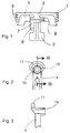
- FIG. 1 shows a piston according to the invention in longitudinal section.
- the piston (1) is made in one piece and has a piston skirt (2) consisting of only two Segments.
- the bearing point (3) for fastening the connecting rod (4) ( Figure 2) is on Piston plate (5) arranged The bearing point is in one cast together with the Piston (1) generated. Due to the reduced piston skirt (2) and the spatial Arrangement of the bearing point (3), namely radially behind the piston ring grooves (6), is a axially short piston made of nodular cast iron, aluminum and others Materials is formed and therefore suitable for use in the upper performance range is.
- the bearing point (3) is provided with a bore (7).
- FIG. 2 On one side of the depository (3) is a cylindrical surface (8) and on the other side a semi-cylindrical Shell surface (9) provided.
- the connecting rod (4) shown in FIG. 2 has one Pin (10) which corresponds to the bore (7) of the bearing point (3).
- On the End of the pin (10) opposite the pin extends radially outward a pull tab (11).
- Figure 3 shows a cross section along section line III - III. Of the Pin (10) is designed as a hollow cylinder.
- the pull tab (11) is with a semicircular recess (12).
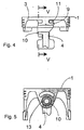
- the connecting rod (4) To install the connecting rod (4), it is inserted axially into the piston (1) such that the pin (10) initially radially next to the bore (7) and the pull tab (11) radially next to the semi-cylindrical outer surface (9) of the bearing (3), in order to then to come into contact with the bearing (3) by moving the connecting rod (4) radially.
- the pin (10) dips into the bore (7) and the pull tab (11) engages with the Recess (12) over the lateral surface (9) ( Figure 4).
- the pin (10) has flats (13) to to ensure better lubrication in the bearing.
- the occurring in operation Load is on the outer circumference of the semi-cylindrical surface (9) and on the The inner circumference of the bore (7) is introduced and distributed evenly over the bearing point (3).
Landscapes
- Engineering & Computer Science (AREA)
- General Engineering & Computer Science (AREA)
- Chemical & Material Sciences (AREA)
- Combustion & Propulsion (AREA)
- Mechanical Engineering (AREA)
- Shafts, Cranks, Connecting Bars, And Related Bearings (AREA)
- Pistons, Piston Rings, And Cylinders (AREA)
Description
- Figur 1
- einen Längsschnitt durch einen erfindungsgemäßen Kolben
- Figur 2
- Teilansicht auf ein erfindungsgemäßes Pleuel
- Figur 3
- Ansicht gemäß Schnittlinie III - III
- Figur 4
- Kolben gemäß Figur 1 mit eingebautem Pleuel
- Figur 5
- Ansicht gemäß Schnittlinie V - V
Claims (6)
- Kolben-Pleuelverbindung, insbesondere für Brennkraftmaschinen, wobei am Pleuelkopf ein fest mit dem Pleuel verbundener, einseitig auskragender Zapfen angeordnet ist, der in einer am Kolbenboden als Lagerstelle ausgebildeten Bohrung gehalten ist, dadurch gekennzeichnet, daß das Pleuel (4) an dem Zapfen (10) gegenüberliegenden Endbereich eine zum Zapfen (10) radial in Richtung Kolbenboden (5) versetzt angeordnete Zuglasche (11) aufweist, die mit der Lagerstelle (3) zusammenwirkt, so daß die in Betrieb auftretende Lasteinleitung durch Zapfen (10) und Zuglasche (11) gleichmäßig verteilt ist.
- Kolben-Pleuelverbindung nach Anspruch 1, dadurch gekennzeichnet, daß die Lagerstelle (3) einen Bereich mit etwa halbzylindrischer Mantelfläche (9) aufweist, auf die die Zuglasche (11) aufschiebbar ist.
- Kolben-Pleuelverbindung nach Anspruch 1 und 2, dadurch gekennzeichnet, daß die Zuglasche (11) einstückig mit dem Pleuel (4) verbunden ist.
- Kolben-Pleuelverbindung nach den Ansprüchen 1 bis 3, dadurch gekennzeichnet, daß die Zuglasche (11) eine etwa halbkreisförmige Ausnehmung (12) aufweist.
- Kolben-Pleuelverbindung nach den Ansprüchen 1 bis 4, dadurch gekennzeichnet, daß der Zapfen (10) als Hohlzylinder ausgebildet ist.
- Kolben-Pleuelverbindung nach den Ansprüchen 1 bis 5, dadurch gekennzeichnet, daß der Hohlzylinder Abflachungen (13) an seiner Mantelfläche aufweist.
Applications Claiming Priority (2)
| Application Number | Priority Date | Filing Date | Title |
|---|---|---|---|
| DE1995144418 DE19544418C1 (de) | 1995-11-29 | 1995-11-29 | Kolben-Pleuelverbindung |
| DE19544418 | 1995-11-29 |
Publications (2)
| Publication Number | Publication Date |
|---|---|
| EP0777072A1 EP0777072A1 (de) | 1997-06-04 |
| EP0777072B1 true EP0777072B1 (de) | 1999-12-15 |
Family
ID=7778657
Family Applications (1)
| Application Number | Title | Priority Date | Filing Date |
|---|---|---|---|
| EP19960113124 Expired - Lifetime EP0777072B1 (de) | 1995-11-29 | 1996-08-16 | Kolben-Pleuelverbindung |
Country Status (2)
| Country | Link |
|---|---|
| EP (1) | EP0777072B1 (de) |
| DE (1) | DE19544418C1 (de) |
Families Citing this family (3)
| Publication number | Priority date | Publication date | Assignee | Title |
|---|---|---|---|---|
| DE19734654C1 (de) * | 1997-08-11 | 1998-08-27 | Ae Goetze Gmbh | Kolben für Brennkraftmaschinen |
| DE19802284A1 (de) * | 1998-01-22 | 1999-07-29 | Man Nutzfahrzeuge Ag | Kolben-Pleuelverbindung für Tauchkolben |
| DE19903915C2 (de) * | 1999-02-01 | 2003-10-16 | Peter Pelz | Hubkolbenmaschine sowie Verfahren zum Herstellen eines Pleuels |
Family Cites Families (2)
| Publication number | Priority date | Publication date | Assignee | Title |
|---|---|---|---|---|
| DE2407866A1 (de) * | 1974-02-19 | 1975-08-28 | Schmidt Gmbh Karl | Tauchkolben |
| DE4337473C2 (de) * | 1993-11-03 | 1998-10-29 | Ae Goetze Gmbh | Kolben-Pleuel-Einheit |
-
1995
- 1995-11-29 DE DE1995144418 patent/DE19544418C1/de not_active Expired - Fee Related
-
1996
- 1996-08-16 EP EP19960113124 patent/EP0777072B1/de not_active Expired - Lifetime
Also Published As
| Publication number | Publication date |
|---|---|
| EP0777072A1 (de) | 1997-06-04 |
| DE19544418C1 (de) | 1997-07-31 |
Similar Documents
| Publication | Publication Date | Title |
|---|---|---|
| DE69800204T2 (de) | Verbesserte Nockenwelle einer Brennkraftmaschine | |
| DE3604661C2 (de) | ||
| DE2253868A1 (de) | Einteiliger, mit einer pleuelstange verbundener kolben | |
| EP1092104A1 (de) | Kolbenbolzenbuchse | |
| DE4330565C1 (de) | Kurbelwellenlager | |
| EP0714485B1 (de) | Leichtmetallkolben für hochbelastete verbrennungsmotoren | |
| EP1716355B1 (de) | Kolbenbolzenlager für kolben eines verbrennungsmotors | |
| DE69506386T2 (de) | Achse für zweiteiligen kolben | |
| DE2723585C2 (de) | Verwendung eines Gleitlagers | |
| EP3268641B1 (de) | Pleuel mit einem kugelgelenk | |
| EP1509712A1 (de) | Kolbenbolzenlager fuer verbrennungsmotoren | |
| DE10307908B4 (de) | Mehrteiliger Kolben | |
| EP0777072B1 (de) | Kolben-Pleuelverbindung | |
| EP0897058A2 (de) | Kolben für Brennkraftmaschinen | |
| DE19543359C1 (de) | Kolben für Brennkraftmaschinen | |
| DE19908670A1 (de) | Kolben für Brennkraftmaschinen | |
| DE2430829A1 (de) | Kolben fuer verbrennungskraftmaschinen | |
| DE102020110793A1 (de) | Kurbelwelle mit Ölversorgung | |
| DE102016208907A1 (de) | Bogenförmige Anlaufscheibe für ein Zylinderkurbelgehäuse einer Hubkolben-Brennkraftmaschine | |
| DE102009018981A1 (de) | Kolben für eine Hubkolbenmaschine | |
| EP1920174B1 (de) | Verlaufende bolzenbohrungsgeometrie für einen kolben einer brennkraftmaschine | |
| DE3733910C2 (de) | ||
| DE3005082A1 (de) | Leichtmetallkolben | |
| DE4210342C2 (de) | Mehrteiliger Verdichtungsring | |
| DE3446760C3 (de) | Kolben, insbesondere eines Verbrennungsmotors |
Legal Events
| Date | Code | Title | Description |
|---|---|---|---|
| PUAI | Public reference made under article 153(3) epc to a published international application that has entered the european phase |
Free format text: ORIGINAL CODE: 0009012 |
|
| AK | Designated contracting states |
Kind code of ref document: A1 Designated state(s): FR GB IT |
|
| 17P | Request for examination filed |
Effective date: 19970617 |
|
| RAP3 | Party data changed (applicant data changed or rights of an application transferred) |
Owner name: FEDERAL-MOGUL BURSCHEID GMBH |
|
| GRAG | Despatch of communication of intention to grant |
Free format text: ORIGINAL CODE: EPIDOS AGRA |
|
| GRAG | Despatch of communication of intention to grant |
Free format text: ORIGINAL CODE: EPIDOS AGRA |
|
| GRAH | Despatch of communication of intention to grant a patent |
Free format text: ORIGINAL CODE: EPIDOS IGRA |
|
| 17Q | First examination report despatched |
Effective date: 19990526 |
|
| RBV | Designated contracting states (corrected) |
Designated state(s): FR GB IT |
|
| REG | Reference to a national code |
Ref country code: DE Ref legal event code: 8566 |
|
| GRAH | Despatch of communication of intention to grant a patent |
Free format text: ORIGINAL CODE: EPIDOS IGRA |
|
| GRAA | (expected) grant |
Free format text: ORIGINAL CODE: 0009210 |
|
| AK | Designated contracting states |
Kind code of ref document: B1 Designated state(s): FR GB IT |
|
| PG25 | Lapsed in a contracting state [announced via postgrant information from national office to epo] |
Ref country code: IT Free format text: LAPSE BECAUSE OF FAILURE TO SUBMIT A TRANSLATION OF THE DESCRIPTION OR TO PAY THE FEE WITHIN THE PRESCRIBED TIME-LIMIT;WARNING: LAPSES OF ITALIAN PATENTS WITH EFFECTIVE DATE BEFORE 2007 MAY HAVE OCCURRED AT ANY TIME BEFORE 2007. THE CORRECT EFFECTIVE DATE MAY BE DIFFERENT FROM THE ONE RECORDED. Effective date: 19991215 Ref country code: GB Free format text: LAPSE BECAUSE OF FAILURE TO SUBMIT A TRANSLATION OF THE DESCRIPTION OR TO PAY THE FEE WITHIN THE PRESCRIBED TIME-LIMIT Effective date: 19991215 Ref country code: FR Free format text: LAPSE BECAUSE OF FAILURE TO SUBMIT A TRANSLATION OF THE DESCRIPTION OR TO PAY THE FEE WITHIN THE PRESCRIBED TIME-LIMIT Effective date: 19991215 |
|
| EN | Fr: translation not filed | ||
| GBV | Gb: ep patent (uk) treated as always having been void in accordance with gb section 77(7)/1977 [no translation filed] |
Effective date: 19991215 |
|
| PLBE | No opposition filed within time limit |
Free format text: ORIGINAL CODE: 0009261 |
|
| STAA | Information on the status of an ep patent application or granted ep patent |
Free format text: STATUS: NO OPPOSITION FILED WITHIN TIME LIMIT |
|
| 26N | No opposition filed |