EP0777041B1 - Moteur à combustion interne avec un capteur des gaz de combustion imbrûlés et un procédé pour évaluer la performance d'un moteur à combustion interne - Google Patents
Moteur à combustion interne avec un capteur des gaz de combustion imbrûlés et un procédé pour évaluer la performance d'un moteur à combustion interne Download PDFInfo
- Publication number
- EP0777041B1 EP0777041B1 EP96308618A EP96308618A EP0777041B1 EP 0777041 B1 EP0777041 B1 EP 0777041B1 EP 96308618 A EP96308618 A EP 96308618A EP 96308618 A EP96308618 A EP 96308618A EP 0777041 B1 EP0777041 B1 EP 0777041B1
- Authority
- EP
- European Patent Office
- Prior art keywords
- venturi
- crankcase
- engine
- sensor
- blow
- Prior art date
- Legal status (The legal status is an assumption and is not a legal conclusion. Google has not performed a legal analysis and makes no representation as to the accuracy of the status listed.)
- Expired - Lifetime
Links
- 238000002485 combustion reaction Methods 0.000 title claims description 14
- 238000000034 method Methods 0.000 title claims description 10
- 239000007789 gas Substances 0.000 claims description 56
- 239000000919 ceramic Substances 0.000 claims description 3
- 239000012530 fluid Substances 0.000 claims 1
- 230000006870 function Effects 0.000 description 6
- 238000012544 monitoring process Methods 0.000 description 6
- 239000000446 fuel Substances 0.000 description 5
- 238000009423 ventilation Methods 0.000 description 5
- 238000005259 measurement Methods 0.000 description 4
- 230000036541 health Effects 0.000 description 3
- 239000000203 mixture Substances 0.000 description 3
- 238000012546 transfer Methods 0.000 description 3
- 238000012986 modification Methods 0.000 description 2
- 230000004048 modification Effects 0.000 description 2
- 210000002445 nipple Anatomy 0.000 description 2
- 230000001737 promoting effect Effects 0.000 description 2
- 244000304337 Cuminum cyminum Species 0.000 description 1
- UFHFLCQGNIYNRP-UHFFFAOYSA-N Hydrogen Chemical compound [H][H] UFHFLCQGNIYNRP-UHFFFAOYSA-N 0.000 description 1
- 229910000831 Steel Inorganic materials 0.000 description 1
- 230000002411 adverse Effects 0.000 description 1
- 230000004075 alteration Effects 0.000 description 1
- XAGFODPZIPBFFR-UHFFFAOYSA-N aluminium Chemical compound [Al] XAGFODPZIPBFFR-UHFFFAOYSA-N 0.000 description 1
- 229910052782 aluminium Inorganic materials 0.000 description 1
- QVGXLLKOCUKJST-UHFFFAOYSA-N atomic oxygen Chemical compound [O] QVGXLLKOCUKJST-UHFFFAOYSA-N 0.000 description 1
- 230000008859 change Effects 0.000 description 1
- 239000000567 combustion gas Substances 0.000 description 1
- 230000006835 compression Effects 0.000 description 1
- 238000007906 compression Methods 0.000 description 1
- 238000011109 contamination Methods 0.000 description 1
- 230000001419 dependent effect Effects 0.000 description 1
- 229920003247 engineering thermoplastic Polymers 0.000 description 1
- 230000007613 environmental effect Effects 0.000 description 1
- 230000014509 gene expression Effects 0.000 description 1
- 239000001257 hydrogen Substances 0.000 description 1
- 229910052739 hydrogen Inorganic materials 0.000 description 1
- 238000002347 injection Methods 0.000 description 1
- 239000007924 injection Substances 0.000 description 1
- 238000012886 linear function Methods 0.000 description 1
- 239000007788 liquid Substances 0.000 description 1
- 239000000463 material Substances 0.000 description 1
- 239000001301 oxygen Substances 0.000 description 1
- 229910052760 oxygen Inorganic materials 0.000 description 1
- 238000007789 sealing Methods 0.000 description 1
- 239000010959 steel Substances 0.000 description 1
- 238000013022 venting Methods 0.000 description 1
- XLYOFNOQVPJJNP-UHFFFAOYSA-N water Substances O XLYOFNOQVPJJNP-UHFFFAOYSA-N 0.000 description 1
Images


Classifications
-
- F—MECHANICAL ENGINEERING; LIGHTING; HEATING; WEAPONS; BLASTING
- F01—MACHINES OR ENGINES IN GENERAL; ENGINE PLANTS IN GENERAL; STEAM ENGINES
- F01M—LUBRICATING OF MACHINES OR ENGINES IN GENERAL; LUBRICATING INTERNAL COMBUSTION ENGINES; CRANKCASE VENTILATING
- F01M13/00—Crankcase ventilating or breathing
-
- F—MECHANICAL ENGINEERING; LIGHTING; HEATING; WEAPONS; BLASTING
- F01—MACHINES OR ENGINES IN GENERAL; ENGINE PLANTS IN GENERAL; STEAM ENGINES
- F01M—LUBRICATING OF MACHINES OR ENGINES IN GENERAL; LUBRICATING INTERNAL COMBUSTION ENGINES; CRANKCASE VENTILATING
- F01M11/00—Component parts, details or accessories, not provided for in, or of interest apart from, groups F01M1/00 - F01M9/00
- F01M11/10—Indicating devices; Other safety devices
-
- F—MECHANICAL ENGINEERING; LIGHTING; HEATING; WEAPONS; BLASTING
- F02—COMBUSTION ENGINES; HOT-GAS OR COMBUSTION-PRODUCT ENGINE PLANTS
- F02B—INTERNAL-COMBUSTION PISTON ENGINES; COMBUSTION ENGINES IN GENERAL
- F02B77/00—Component parts, details or accessories, not otherwise provided for
- F02B77/08—Safety, indicating, or supervising devices
- F02B77/085—Safety, indicating, or supervising devices with sensors measuring combustion processes, e.g. knocking, pressure, ionization, combustion flame
-
- F—MECHANICAL ENGINEERING; LIGHTING; HEATING; WEAPONS; BLASTING
- F02—COMBUSTION ENGINES; HOT-GAS OR COMBUSTION-PRODUCT ENGINE PLANTS
- F02B—INTERNAL-COMBUSTION PISTON ENGINES; COMBUSTION ENGINES IN GENERAL
- F02B3/00—Engines characterised by air compression and subsequent fuel addition
- F02B3/06—Engines characterised by air compression and subsequent fuel addition with compression ignition
Definitions
- the present invention relates generally to engine crankcase gas blow-by sensors and to a method of evaluating performance of an internal combustion engine. More particularly, this invention relates to an engine crankcase gas blow-by sensor using a venturi and a differential pressure transducer to measure volumetric flow of blow-by gases.
- the pressure within an internal combustion engine crankcase should be maintained at a level equal to or slightly less than atmospheric pressure to prevent external oil leakage through the various gasketed joints, such as that between the valve cover and the cylinder head.
- a so-called blow-by gas is emitted in the crankcase as a result of leaks of intake air-fuel mixture and combustion gases through the clearances around piston rings, during the compression, combustion and/or exhaust cycles. Because of these blow-by gases, the crankcase pressure will inherently rise, promoting leakage of oil from the crankcase.
- the crankcase pressure was vented to the atmosphere through a breather in order to solve this problem.
- blow-by gases in the crankcase be vented back to the combustion chamber rather than being released to the atmosphere.
- closed crankcase ventilation (CCV) systems recycle the blow-by gas by burning these gases together with the intake air-fuel mixture.
- a good way to measure the volume of blow-by gas entering the crankcase is to measure the pressure of such gases in the crankcase.
- closed crankcase ventilation systems do not allow any of the crankcase gases to be vented through an orifice, which would be required in order to measure the crankcase pressure.
- the present invention is directed toward meeting this need.
- US-A-3,862,624 discloses an engine which uses oxygen and an excess of hydrogen as fuel and which has a substantially closed exhaust system which recirculates the gaseous part of the exhaust and mixes it with fresh gaseous feed and recirculated blow-by gas.
- a flow meter is provided for the mixture of recirculated exhaust gas, fresh gaseous fuel and blow-by gas.
- crankcase gases are allowed to flow through a venturi which includes high pressure and low pressure taps.
- the high and low pressure taps are coupled to a differential pressure transducer which produces an output that is proportional to the volumetric flow of crankcase gases through the venturi.
- the use of a venturi in conjunction with a differential pressure sensor offers a low resistance path for the flow of crankcase gases and allows continuous monitoring of blow-by without exceeding the operating pressure limitations of various oil seals.
- Such a sensor is particularly suited for closed crankcase ventilation (ccv) systems, as it doesn't require venting of crankcase gases to the atmosphere (but will also work well on open systems).
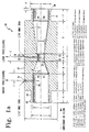
- FIG. la is a cross-sectional view of a preferred embodiment of the venturi of the present invention.
- FIG. lb is an end view of the venturi of FIG. 1.
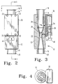
- FIG. 2 is a top plan view of the venturi of FIG. 1 with the differential pressure transducer mounted thereon.
- FIG. 3 is a cross-sectional view of the venturi and differential pressure sensor of FIG. 2.
- FIG. 4 is an end view of the venturi and differential pressure sensor of FIG. 2.
- FIG. 5 is a graph of differential pressure as a function of the flow transfer function of the venturi of FIG. 2.
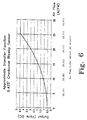
- FIG. 6 is a graph of the voltage output signal of the differential pressure sensor of FIG. 2 as a function of air flow through the venturi.
- the present invention involves the sensing of crankcase blow-by gases by measuring the volumetric flow of such gases rather than the prior art method of measuring the pressure of these gases.
- Volumetric flow of the blow-by gases is accomplished by routing a portion of these gases through a venturi which has high pressure and low pressure taps therein.
- a differential pressure sensor is then attached to the high and low pressure taps in order to measure the pressure differential between the taps.
- This differential pressure is related to the volumetric flow of blow-by gases through the venturi, and hence the volumetric flow of blow-by gases around the engine pistons.
- the venturi 10 includes a generally cylindrical venturi body 12 having an inlet port 14 and an outlet port 16 attached thereto.
- the inlet port 14 includes a hose connection nipple 18 while the outlet port 16 includes a hose connection nipple 20.
- Crankcase gases may thus be routed to the venturi 10 via a suitable hose (not shown), and crankcase gases exiting the venturi 10 may be routed back to the crankcase via a second suitable hose (not shown).
- the venturi 10 is preferably formed from aluminum, steel or an injection molded engineering thermoplastic, or any other suitable material.
- venturi 10 will vary depending upon the engine size with which the venturi is associated.
- the dimensions given for the venturi 10 of FIG. la are preferred for use with a K50 diesel engine manufactured by the Cummins Engine Company of Columbus, Indiana. Because the venturi effectively amplifies the flow rate of crankcase gases through the venturi, different venturi sizes will be appropriate for different size engines.
- the venturi 10 has an inlet port 14 internal diameter of 1 inch (25.4mm).
- the outlet port 16 also has an internal diameter of 1 inch (25.4).
- the venturi throat 22 has an internal diameter of 0.425 inches (10.795mm.) Dimensions for the other portions of the venturi 10 are illustrated in FIG. la.
- a high pressure tap 24 is formed from the exterior surface of the venturi body 12 to the inlet bore 26 which extends through the inlet port 14.
- a low pressure tap 28 is formed from the exterior surface of the venturi body 12 to the venturi throat 22.
- a differential pressure sensor 30 is coupled to the venturi body 12 by means of four screws 32 which bore into the body 12.
- the differential pressure sensor 30 is preferably a variable capacitive on ceramic differential pressure sensor such as a model P604 manufactured by Kavlico of Moorepark, California, but any type of differential pressure sensor may be utilized in the present invention.
- the differential pressure sensor 30 is mounted to the venturi body 12 such that the high pressure tap 24 is aligned with the inlet 34 to the high pressure side of the differential pressure sensor 30.
- the low pressure tap 28 communicates with the inlet 36 of the low pressure side of the differential pressure sensor 30.
- the differential pressure sensor 30 is preferably of the wet-dry type, therefore the low pressure side of the sensor includes a filter element 38 in order to prevent liquid, such as uncombusted fuel and oil, to enter the low pressure side of the differential pressure sensor 30.
- the output of the differential pressure sensor 30 is a voltage which is proportional to the differential pressure across the high pressure tap 24 and the low pressure tap 28. This output voltage is supplied to a multi-pin electrical connector 40.
- the connector 40 additionally accepts the input voltage which is used to power the differential pressure sensor 30.
- the venturi 10 of FIG. la is capable of flowing in excess of 50 actual cubic feet per minute (ACFM) (1.4 cubic metres per minute) air or crankcase gas, although the flow rate will be approximately 26 ACFM (0.728 cubic metres per minute) maximum for the model K50 engine for which the venturi 10 was designed.
- a flow rate of 26 ACFM (0.728 cubic metres per minute) results in approximately 30 inches (760 mm) of water pressure differential developed across the pressure taps 24 and 28.
- FIG. 5 illustrates the differential pressure developed across the pressure taps 24 and 28 of the venturi 10 as a function of gas flow through the venturi 10.
- This graph illustrates that the transfer function of gas flow vs. differential pressure for the venturi 10 is not linear.
- the combination venturi body 12 and differential pressure sensor 30 is preferably mounted in a substantially vertical orientation in order to allow gas to run out of the venturi in order to prevent build-up and contamination within the differential pressure sensor 30. Such build-up will change the measured pressure and result in inaccuracies in the measurement of crankcase gas flow.
- the differential pressure sensor 30 is mounted to the venturi body 12 by means of an appropriate sealing gasket which forms an airtight seal between the differential pressure sensor 30 and the high pressure tap 24 and low pressure tap 28.
- the output voltage of the differential pressure sensor 30 is a non-linear function of media volumetric flow, which tracks the actual differential pressure developed across the high and low pressure taps of the venturi.
- the input voltage to the differential pressure sensor 30 is 5.0+/-5% VDC. Because the sensor 30 is ratiometric to the input voltage, the output voltage illustrated in FIG. 6 assumes a 5.0 VDC input voltage. It will be appreciated by those skilled in the art that the transfer function of FIG. 6 allows an engine monitoring system to determine the flow-rate of crankcase gases through the venturi by monitoring the output voltage of the differential pressure sensor 30. This information may be used in different ways by the engine monitoring system.
- the output voltage of the differential pressure sensor 30 may be monitored for an instantaneous increase of blow-by gas flow, indicative of a catastrophic failure within the engine.
- the amount of instantaneous increase necessary to signal a catastrophic failure may be made a calibratable threshold point within the engine monitoring system and is dependent upon engine size.
- an indicator light may be used to alert the driver of the situation.
- the output voltage of the differential pressure sensor 30 may also be used to record crankcase gas flow rate over time in order to chart the wear of the engine and hence predict when the engine will require an overhaul.
- the engine monitoring system may use a filtered linear projection in order to determine at what time the engine blow-by gases have increased to the point where maximum performance is no longer available from the engine. Appropriate servicing can then be scheduled for the vehicle prior to that time.
- the present invention allows useful measurement of engine crankcase blow-by which was previously unavailable in closed crankcase ventilation systems. Measurement of such blow-by gases can provide information to signal catastrophic failures within the engine as well as to predict when major engine servicing will be required in the future. Such information may be used to minimize downtime of the engine and to prevent expensive catastrophic engine failure.
Landscapes
- Engineering & Computer Science (AREA)
- Mechanical Engineering (AREA)
- General Engineering & Computer Science (AREA)
- Chemical & Material Sciences (AREA)
- Combustion & Propulsion (AREA)
- Lubrication Details And Ventilation Of Internal Combustion Engines (AREA)
- Testing Of Engines (AREA)
Claims (11)
- Moteur comprenant un détecteur de gaz de carter et un carter de moteur permettant de recevoir les gaz de carter par l'intermédiaire d'un passage d'écoulement gazeux ; caractérisé par :une buse (10) placée dans le passage d'écoulement gazeux de sorte que les gaz de carter s'écoulent, en utilisation, dans la buse (10) et qu'il sont renvoyés de la buse (10) au carter ;un robinet haute pression (24) s'étendant d'une partie extérieure de la buse (10) à une partie intérieure (26) de la buse (10) ;un robinet basse pression (28) s'étendant de l'extérieur de la buse à l'intérieur de la buse (22) ; etun détecteur (30) couplé à la buse (10) et permettant de mesurer une différence de pression entre le robinet haute pression (24) et le robinet basse pression (28).
- Détecteur de gaz de carter de moteur selon la revendication 1 d'un moteur à combustion interne, comprenant :au moins un cylindre ;au moins un piston placé, de façon à pouvoir coulisser, dans l'au moins un cylindre afin de définir une chambre de combustion au-dessus du piston ;le carter étant couplé à au moins un cylindre, dans lequel une partie intérieure du carter est en communication fluidique avec une partie intérieure d'au moins un piston situé au-dessous d'au moins un piston par l'intermédiaire d'au moins le passage d'écoulement gazeux, dans lequel les gaz de carter de combustion qui se trouvent au niveau de l'au moins un piston peuvent entrer dans le carter.
- Appareil selon la revendication 1 ou la revendication 2, dans lequel le robinet haute pression (24) s'étend de l'extérieur de la buse à une partie intérieure d'un alésage d'entrée (26) de la buse (10).
- Appareil selon la revendication 1 ou la revendication 2, dans lequel le robinet basse pression (28) s'étend de l'extérieur de la buse à une partie intérieure d'un col (22) de la buse (10).
- Appareil selon la revendication 1 ou la revendication 2, dans lequel le détecteur (30) comprend un détecteur de pression différentielle de type sec ou humide.
- Appareil selon la revendication 1 ou la revendication 2, dans lequel le détecteur (30) comprend une capacité variable sur un détecteur de pression en céramique.
- Appareil selon la revendication 1 ou la revendication 2, dans lequel la buse (10) est montée sensiblement verticalement afin de permettre au gaz de sortir de la buse (10).
- Procédé permettant d'évaluer les performances d'un moteur à combustion interne, caractérisé par les étapes consistant à :(a) diriger au moins une partie des gaz de carter entrant dans un carter du moteur dans une buse (10) puis de nouveau dans le carter, la buse (10) présentant un robinet haute pression (24) et un robinet basse pression (28) ;(b) mesurer une différence de pression entre le robinet haute pression (24) et le robinet basse pression (28) ; et(c) émettre un signal proportionnel à la différence de pression mesurée.
- Procédé selon la revendication 8, dans lequel l'étape (b) est exécutée par un détecteur de pression différentielle de type sec-humide (30).
- Procédé selon la revendication 8, dans lequel l'étape (b) est exécutée par une capacité variable sur un détecteur de pression en céramique (30).
- Procédé selon la revendication 8, dans lequel le signal est un signal de tension.
Applications Claiming Priority (2)
| Application Number | Priority Date | Filing Date | Title |
|---|---|---|---|
| US564419 | 1983-12-22 | ||
| US56441995A | 1995-11-25 | 1995-11-25 |
Publications (3)
| Publication Number | Publication Date |
|---|---|
| EP0777041A2 EP0777041A2 (fr) | 1997-06-04 |
| EP0777041A3 EP0777041A3 (fr) | 1998-04-01 |
| EP0777041B1 true EP0777041B1 (fr) | 2002-03-13 |
Family
ID=24254397
Family Applications (1)
| Application Number | Title | Priority Date | Filing Date |
|---|---|---|---|
| EP96308618A Expired - Lifetime EP0777041B1 (fr) | 1995-11-25 | 1996-11-28 | Moteur à combustion interne avec un capteur des gaz de combustion imbrûlés et un procédé pour évaluer la performance d'un moteur à combustion interne |
Country Status (3)
| Country | Link |
|---|---|
| EP (1) | EP0777041B1 (fr) |
| JP (1) | JPH09177530A (fr) |
| DE (1) | DE69619772T2 (fr) |
Cited By (3)
| Publication number | Priority date | Publication date | Assignee | Title |
|---|---|---|---|---|
| CN102749203A (zh) * | 2011-04-21 | 2012-10-24 | 浙江派尼尔机电有限公司 | 一种船用发动机测试方法、装置和系统 |
| CN103003536A (zh) * | 2010-05-14 | 2013-03-27 | 沙勒工业自动化技术两合公司 | 为操作发动机确定气体和/或悬浮微粒读数的系统和方法 |
| US9447745B2 (en) | 2011-09-15 | 2016-09-20 | General Electric Company | System and method for diagnosing an engine |
Families Citing this family (11)
| Publication number | Priority date | Publication date | Assignee | Title |
|---|---|---|---|---|
| FR2864156B1 (fr) * | 2003-12-18 | 2006-02-03 | Renault Sas | Dispositif de controle moteur |
| FR2867564B1 (fr) * | 2004-03-11 | 2006-06-23 | Total France | Procede et dispositif de mesure en temps reel de la consommation d'huile du systeme de separation d'huile moteur |
| EP1922476B1 (fr) | 2005-07-18 | 2009-01-07 | Danfoss A/S | Procédé et système de détection de panne moteur |
| DE102011007172A1 (de) * | 2011-04-12 | 2012-10-18 | Man Diesel & Turbo Se | Brennkraftmaschine |
| WO2013057809A1 (fr) * | 2011-10-19 | 2013-04-25 | トヨタ自動車 株式会社 | Compresseur de suralimentation |
| US10060394B2 (en) * | 2014-09-10 | 2018-08-28 | Denso International America, Inc. | Evaporative system |
| FR3051020B1 (fr) * | 2016-05-04 | 2020-03-20 | Valeo Systemes De Controle Moteur | Systeme de controle des emissions d'un vehicule automobile |
| CN110160792B (zh) * | 2018-11-15 | 2020-12-25 | 北京机电工程研究所 | 一种动力系统动态模拟试验方法 |
| JP7188275B2 (ja) * | 2019-05-16 | 2022-12-13 | トヨタ自動車株式会社 | 車載内燃機関の異常診断装置 |
| CN112051047B (zh) * | 2020-09-07 | 2022-12-09 | 中国第一汽车股份有限公司 | 一种曲轴箱通风系统携出机油测量及回收装置 |
| CN113670624B (zh) * | 2021-07-30 | 2023-09-19 | 东风汽车集团股份有限公司 | 一种发动机检测系统以及发动机检测方法 |
Citations (1)
| Publication number | Priority date | Publication date | Assignee | Title |
|---|---|---|---|---|
| US3862624A (en) * | 1970-10-10 | 1975-01-28 | Patrick Lee Underwood | Oxygen-hydrogen fuel use for combustion engines |
Family Cites Families (3)
| Publication number | Priority date | Publication date | Assignee | Title |
|---|---|---|---|---|
| FR1428610A (fr) * | 1965-01-07 | 1966-02-18 | Alsacienne Constr Meca | Dispositif de sécurité pour moteur à combustion interne |
| US4481828A (en) * | 1983-01-27 | 1984-11-13 | Phillips Petroleum Company | Differential flow rate sensor |
| FR2641575B1 (fr) * | 1989-01-11 | 1991-05-17 | Guilcher Guy | Dispositif de detection des augmentations de pression dans les carters des moteurs a combustion interne |
-
1996
- 1996-11-28 EP EP96308618A patent/EP0777041B1/fr not_active Expired - Lifetime
- 1996-11-28 DE DE1996619772 patent/DE69619772T2/de not_active Expired - Lifetime
- 1996-11-29 JP JP31991396A patent/JPH09177530A/ja active Pending
Patent Citations (1)
| Publication number | Priority date | Publication date | Assignee | Title |
|---|---|---|---|---|
| US3862624A (en) * | 1970-10-10 | 1975-01-28 | Patrick Lee Underwood | Oxygen-hydrogen fuel use for combustion engines |
Cited By (4)
| Publication number | Priority date | Publication date | Assignee | Title |
|---|---|---|---|---|
| CN103003536A (zh) * | 2010-05-14 | 2013-03-27 | 沙勒工业自动化技术两合公司 | 为操作发动机确定气体和/或悬浮微粒读数的系统和方法 |
| CN103003536B (zh) * | 2010-05-14 | 2015-04-15 | 沙勒工业自动化技术两合公司 | 为操作发动机确定气体和/或悬浮微粒读数的系统和方法 |
| CN102749203A (zh) * | 2011-04-21 | 2012-10-24 | 浙江派尼尔机电有限公司 | 一种船用发动机测试方法、装置和系统 |
| US9447745B2 (en) | 2011-09-15 | 2016-09-20 | General Electric Company | System and method for diagnosing an engine |
Also Published As
| Publication number | Publication date |
|---|---|
| DE69619772D1 (de) | 2002-04-18 |
| JPH09177530A (ja) | 1997-07-08 |
| DE69619772T2 (de) | 2002-09-19 |
| EP0777041A2 (fr) | 1997-06-04 |
| EP0777041A3 (fr) | 1998-04-01 |
Similar Documents
| Publication | Publication Date | Title |
|---|---|---|
| US6575022B1 (en) | Engine crankcase gas blow-by sensor | |
| EP0777041B1 (fr) | Moteur à combustion interne avec un capteur des gaz de combustion imbrûlés et un procédé pour évaluer la performance d'un moteur à combustion interne | |
| EP1406005B1 (fr) | Méthode et appareil de surveillance de valves de commande | |
| JP3116556B2 (ja) | 内燃機関の燃料タンク系の気密チェック装置 | |
| US5898103A (en) | Arrangement and method for checking the tightness of a vessel | |
| CA2245438A1 (fr) | Systeme de detection des defaillances pour capteur de pression du carburant | |
| US6065335A (en) | Method for detecting the fill level quantity of a tank system | |
| US4719792A (en) | Method and a device for testing the tightness of an engine | |
| US5988149A (en) | Pressure sensing system for an internal combustion engine | |
| FI79887B (fi) | Foerfarande och anordning foer taethetsprovning av en foerbraenningsmotor. | |
| JP2009528473A (ja) | 内燃機関用の排気ターボチャージャ | |
| CN110500209A (zh) | 一种egr单向阀的监测系统及监测方法 | |
| US6779516B1 (en) | Closed crankcase ventilation system with flow meter for monitoring engine operation | |
| US6014961A (en) | Internal combustion engine intake sensing system | |
| CA2163044A1 (fr) | Essai d'etancheite des cylindres d'un moteur | |
| US5385134A (en) | System for monitoring leakage into exhaust lines | |
| CN111550312B (zh) | 内燃机的异常判定装置 | |
| JP2019506608A (ja) | リアルタイム流体種質量流量計 | |
| US5477837A (en) | Controller for internal combustion engine | |
| KR920003949B1 (ko) | 내연기관의 압력취출구 | |
| JPH0419312A (ja) | エンジンブローバイガスの流量検知装置およびその検知方法 | |
| KR100218165B1 (ko) | Egr밸브의 유량특성 시험장치 | |
| US6463795B2 (en) | Method for testing an internal combustion engine for assembly and/or manufacturing faults | |
| US11408312B2 (en) | PCV valve | |
| JPH0763122A (ja) | 排ガス還流管の異常判定装置 |
Legal Events
| Date | Code | Title | Description |
|---|---|---|---|
| PUAI | Public reference made under article 153(3) epc to a published international application that has entered the european phase |
Free format text: ORIGINAL CODE: 0009012 |
|
| AK | Designated contracting states |
Kind code of ref document: A2 Designated state(s): DE FR GB |
|
| PUAL | Search report despatched |
Free format text: ORIGINAL CODE: 0009013 |
|
| AK | Designated contracting states |
Kind code of ref document: A3 Designated state(s): DE FR GB |
|
| 17P | Request for examination filed |
Effective date: 19980904 |
|
| 17Q | First examination report despatched |
Effective date: 20000314 |
|
| RTI1 | Title (correction) |
Free format text: AN INTERNAL COMBUSTION ENGINE WITH AN ENGINE CRANKCASE GAS BLOW-BY SENSOR AND A METHOD OF EVALUATING PERFORMANCE OF AN INTERNAL COMBUSTION ENGINE |
|
| GRAG | Despatch of communication of intention to grant |
Free format text: ORIGINAL CODE: EPIDOS AGRA |
|
| GRAG | Despatch of communication of intention to grant |
Free format text: ORIGINAL CODE: EPIDOS AGRA |
|
| GRAH | Despatch of communication of intention to grant a patent |
Free format text: ORIGINAL CODE: EPIDOS IGRA |
|
| GRAH | Despatch of communication of intention to grant a patent |
Free format text: ORIGINAL CODE: EPIDOS IGRA |
|
| REG | Reference to a national code |
Ref country code: GB Ref legal event code: IF02 |
|
| GRAA | (expected) grant |
Free format text: ORIGINAL CODE: 0009210 |
|
| AK | Designated contracting states |
Kind code of ref document: B1 Designated state(s): DE FR GB |
|
| REF | Corresponds to: |
Ref document number: 69619772 Country of ref document: DE Date of ref document: 20020418 |
|
| ET | Fr: translation filed | ||
| PLBE | No opposition filed within time limit |
Free format text: ORIGINAL CODE: 0009261 |
|
| STAA | Information on the status of an ep patent application or granted ep patent |
Free format text: STATUS: NO OPPOSITION FILED WITHIN TIME LIMIT |
|
| 26N | No opposition filed |
Effective date: 20021216 |
|
| PGFP | Annual fee paid to national office [announced via postgrant information from national office to epo] |
Ref country code: FR Payment date: 20111128 Year of fee payment: 16 |
|
| REG | Reference to a national code |
Ref country code: FR Ref legal event code: ST Effective date: 20130731 |
|
| PG25 | Lapsed in a contracting state [announced via postgrant information from national office to epo] |
Ref country code: FR Free format text: LAPSE BECAUSE OF NON-PAYMENT OF DUE FEES Effective date: 20121130 |
|
| PGFP | Annual fee paid to national office [announced via postgrant information from national office to epo] |
Ref country code: GB Payment date: 20131127 Year of fee payment: 18 Ref country code: DE Payment date: 20131127 Year of fee payment: 18 |
|
| REG | Reference to a national code |
Ref country code: DE Ref legal event code: R082 Ref document number: 69619772 Country of ref document: DE Representative=s name: ANDRAE WESTENDORP PATENTANWAELTE PARTNERSCHAFT, DE |
|
| REG | Reference to a national code |
Ref country code: DE Ref legal event code: R119 Ref document number: 69619772 Country of ref document: DE |
|
| GBPC | Gb: european patent ceased through non-payment of renewal fee |
Effective date: 20141128 |
|
| PG25 | Lapsed in a contracting state [announced via postgrant information from national office to epo] |
Ref country code: GB Free format text: LAPSE BECAUSE OF NON-PAYMENT OF DUE FEES Effective date: 20141128 Ref country code: DE Free format text: LAPSE BECAUSE OF NON-PAYMENT OF DUE FEES Effective date: 20150602 |