EP0776983A1 - Nozzle for blowing gas into molten metal and usage thereof - Google Patents
Nozzle for blowing gas into molten metal and usage thereof Download PDFInfo
- Publication number
- EP0776983A1 EP0776983A1 EP96914400A EP96914400A EP0776983A1 EP 0776983 A1 EP0776983 A1 EP 0776983A1 EP 96914400 A EP96914400 A EP 96914400A EP 96914400 A EP96914400 A EP 96914400A EP 0776983 A1 EP0776983 A1 EP 0776983A1
- Authority
- EP
- European Patent Office
- Prior art keywords
- gas
- blast nozzle
- refractory
- gas blast
- metal pipe
- Prior art date
- Legal status (The legal status is an assumption and is not a legal conclusion. Google has not performed a legal analysis and makes no representation as to the accuracy of the status listed.)
- Granted
Links
Images


Classifications
-
- C—CHEMISTRY; METALLURGY
- C21—METALLURGY OF IRON
- C21C—PROCESSING OF PIG-IRON, e.g. REFINING, MANUFACTURE OF WROUGHT-IRON OR STEEL; TREATMENT IN MOLTEN STATE OF FERROUS ALLOYS
- C21C5/00—Manufacture of carbon-steel, e.g. plain mild steel, medium carbon steel or cast steel or stainless steel
- C21C5/28—Manufacture of steel in the converter
- C21C5/42—Constructional features of converters
- C21C5/46—Details or accessories
- C21C5/48—Bottoms or tuyéres of converters
-
- B—PERFORMING OPERATIONS; TRANSPORTING
- B22—CASTING; POWDER METALLURGY
- B22D—CASTING OF METALS; CASTING OF OTHER SUBSTANCES BY THE SAME PROCESSES OR DEVICES
- B22D1/00—Treatment of fused masses in the ladle or the supply runners before casting
- B22D1/002—Treatment with gases
- B22D1/005—Injection assemblies therefor
-
- C—CHEMISTRY; METALLURGY
- C21—METALLURGY OF IRON
- C21C—PROCESSING OF PIG-IRON, e.g. REFINING, MANUFACTURE OF WROUGHT-IRON OR STEEL; TREATMENT IN MOLTEN STATE OF FERROUS ALLOYS
- C21C7/00—Treating molten ferrous alloys, e.g. steel, not covered by groups C21C1/00 - C21C5/00
- C21C7/04—Removing impurities by adding a treating agent
- C21C7/072—Treatment with gases
Definitions
- This invention relates to a gas blast nozzle for molten metal in a smelting furnace such as an electric furnace or another refining furnace.
- a gas blast nozzle for molten metal that can be repaired easily, and a method of using the same.
- FIG. 5 of the accompanying drawings illustrates examples of conventional gas blast nozzles.
- Fig. 5(a), Fig. 5(b) and Fig.5(c), respectively, show a single pipe nozzle, a double pipe nozzle and a multi-pipe nozzle
- Fig. 5(d) shows a porous plug.
- reference numerals 10 and 11, respectively, denote a gas feed hose and a refractory block in a furnace bottom
- 17 and 18, respectively denote a cooling gas feed pipe and a porous brick.
- 5(c) may be realized by burying a plurality of small metal pipes in a refractory block and such a multi-pipe nozzle has been popularly used for electric furnaces because fine and evenly sized gas bubbles can be produced in molten metal by means of the multi-pipe nozzle.
- Japanese patent application laid-open publication No. 58-81937 discloses a gas blast plug comprising a refractory nozzle block having a bore therethrough and a small metal pipe placed in the bore with an annular gap to an inner surface of the bore.
- FIG. 6 of the accompanying drawings illustrates the gas blast plug according to the above prior art.
- an annular gap is formed between the inner surface of the bore and the outer surface of the small metal pipe 2, such that the thickness of the annular gap is sufficiently thin so as to avoid any leaking of molten metal.
- a gas feed hose (not shown) is connected to the small metal pipe 2.
- the arrangement shown in Fig. 6 seems to be effective for prolonging the service life of a gas blast nozzle, since the gas blast nozzle can be repaired when it has been partly worn away during its usage, and can be served for long term without replacing it.
- the inventors of the present invention have found that, when the gas blast plug according to the above is used in an electric refining furnace, the gas tends to move into the annular gap rather than entering into the molten metal as shown in Fig. 6(b).
- the gas from the small metal pipe 2 is supplied at a low rate and the gas is blown in from the bottom of the furnace, a high static pressure of the molten metal at the bottom of the furnace may resist the gas entering into the molten metal, and the gas may move more easily into the annular gap than into the molten metal.
- the above construction does not provide a solution to this problem.
- the present invention provides a gas blast nozzle that minimizes the breakdown time of a furnace for replacing the gas blast nozzle because it seldom requires the replacement, reduces the work load of the replacing operation under adverse working conditions and is free from the problem of gas leaking through the gas blast nozzle.
- Fig. 1 of the accompanying drawings shows a gas blast nozzle according to the invention.
- Fig. 1(a) is a longitudinal sectional view of the gas blast nozzle itself
- Fig. 1(b) is also a longitudinal sectional view of the gas blast nozzle showing how it is arranged in the bottom of a furnace
- Fig. 1(c) is also a longitudinal section view illustrating it with a coupler for connecting it with a gas feed hose.
- a gas blast nozzle for molten metal comprising a refractory block 4 having a narrow straight bore 3 being bored from the inside to the outside of a furnace, a tubular metal fitting 22 formed in one body with the refractory block 4, a small metal pipe 2 arranged slidably through the straight bore 3 of the refractory block 4 and a metal coupler 23 for connecting a gas hose 15 to an end of the tubular metal fitting 22, and is characterized in that an outer end portion of the small metal pipe 2 is made to penetrate through a rubber block 14 in the metal coupler 23, and the gas 12 fed to the metal coupler 23 is blown into the molten metal in the furnace from the inner end of the small metal pipe 2.
- the tubular metal fitting 22 is tubular at an end and has a saucer-like profile at the other end to snugly receive the bottom of the refractory block 4 so that the refractory block 4 is fitted and bonded to the tubular metal fitting 22 at its bottom to combine them in one body with each other. Since the refractory block 4 and the tubular metal fitting 22 are integrated in one body with each other and the small metal pipe is made to penetrate through the rubber block, gas is securely prevented from leaking through the annular gap between the small metal pipe 2 and the refractory block 4 unlike the case of Fig. 6(b).
- the tubular end of the metal fitting 22 is connected to an end of the metal coupler 23, and the other end of the metal coupler 23 is connected to a gas hose 15.
- the outer end of the small metal pipe 2 is made to penetrate the rubber block 14 and open for the gas hose 15.
- the gap between the outer periphery of the small metal pipe 2 and the inner surface of the metal coupler 23 is sealed by the rubber block 14 so that all the gas 12 fed in from the gas hose 15 is blown into the small metal pipe 2.
- a gas blast nozzle according to the invention may alternatively comprise a plurality of small metal pipes 2 in such a way that the gap between each of the small metal pipes 2 and the corresponding metal coupler 23 is filled with a rubber block 14 so that all the gas fed in may be blown into the small metal pipes 2 regardless of the number of small metal pipes 2.
- the gas blast nozzle 1 is fitted to the tuyere-forming bricks 6 at the refractory bottom 11 of the furnace and secured to an outer shell 19 of the furnace by means of a securing ring 21 and a lock member 20.
- the gap between the nozzle and the tuyere-forming bricks is filled with some castable refractory substance 5.
- the small metal pipe 2 may be a stainless steel pipe having an inner diameter of 1 to 2 mm, although the inner diameter and the number of pipes may be selected depending on the gas flow rate. Additionally, the small metal pipe may be a single pipe or a double pipe. It should be noted that the inner diameter of the straight bore 3 is made greater than the outer diameter of the small metal pipe 2 by 0 to 4 mm in order to allow the small metal pipe 2 to move smoothly vertically.
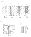
- FIG. 2 illustrates a method of using the gas blast nozzle 1 according to the invention.
- a gas blast nozzle 1 according to the invention is worn away, in particular the inner refractory is worn away during its usage which produces a worn away portion 8 as shown in Fig. 2(a).
- the worn away portion 8 is repaired by moving upward the small metal pipe 2 in the straight bore 3 until the inner end of the small metal pipe 2 projects over the inner surface of the furnace as shown in Fig. 2(b).
- the worn away portion 8 is filled with a refractory material 16 without closing the inner end of the small metal pipe 2 as shown in Fig. 2(c).
- the inner end of the small metal pipe 2 is projecting over the inner surface of the furnace after the worn away portion has been filled with the refractory material 16.
- the inner end of the small metal pipe 2 would neither be buried nor clogged by this projection even if in a usual repairing apparatus of the furnace a lining such as a sand slinger is used to fill the worn away portion 8 with an ordinary refractory material for repairing the lining of the furnace.
- the gas blast nozzle and its peripheral area can be repaired easily, if necessary, in the routine operation for maintaining the furnace bottom and the furnace wall, which consequently prolongs the service life of the gas blast nozzle so that the frequency of replacing the gas blast nozzle will be remarkably reduced.
- the projecting portion of the small metal pipe 2 is immediately molten away and the inner end of the gas blast nozzle will show a profile as shown in Fig. 1(b). Also, the gas blast nozzle operates to blow gas into the molten metal as stably as before.
- Fig. 3 illustrates another embodiment of a gas blast nozzle according to the invention.
- Fig. 3(a) is a longitudinal sectional view of the gas blast nozzle and
- Fig. 3(b) is also a longitudinal sectional view showing how the gas blast nozzle is arranged in the bottom of a furnace.
- the gas blast nozzle of Fig. 3(a) differs from that of Fig. 1(a) in that the refractory block 4 is divided into upper and lower pieces. Otherwise, it is the same as its counterpart of Fig. 1(a).
- the tubular metal fitting 22 is coupled at its outer end to a gas hose 15 by means of a metal coupler 23 and the annular gap around the small metal pipe 2 is sealed by a rubber block 14.
- the gas blast nozzle is also fitted to the tuyere-forming bricks 6 at the refractory bottom 11 of the furnace and secured to the outer shell 19 of the furnace by means of a securing ring 21 and a lock member 20. Also, the gap between the nozzle and the tuyere-forming bricks is filled with some castable refractory substance.
- Fig. 4 illustrates a method of using the gas blast nozzle illustrated in Fig. 3.
- the worn away portion 8 in Fig. 4(a) is repaired by moving upward the small metal pipe 2 in the straight bore until the inner end of the small metal pipe 2 projects over the inner surface of the furnace, replacing the damaged upper piece 4a of the refractory block with a new upper piece 4a (hereinafter referred to as a repairing brick) as shown in Fig. 4(b) and filling the remaining portion with a refractory material 16. Thereafter, the small metal pipe 2 is moved downward until the inner end arrives at the same level as that of the upper surface of the repairing brick 4a.
- the service life of the gas blast nozzle will be further prolonged compared with its repairing where the worn away portion is filled only by a castable refractory material. Additionally, since the small metal pipe 2 is not projecting into the furnace after repairing, it will be consumed at a reduced rate.
- a straight bore having an inner diameter of 5 mm was formed through a refractory block 4 as shown in Fig. 1(a) in order to provide a gas blast nozzle for feeding gas from the bottom of an electric furnace.
- the small metal pipe 2 had an inner diameter of 2 mm, an outer diameter of 4 mm and a length of 2 m and was used with a metal coupler 23 as shown in Fig. 1(c).
- Gas was blown into the molten metal in the furnace at a rate of 30 to 100 liter/min.
- the gas feeding hose 15 as shown in Fig. 1(c) was removed, the small metal pipe 2 was moved upward until the upper end arrived at the same level as that of the surface of a repaired refractory bottom 11 of the furnace and the worn away portion was filled with refractory material. After this repairing, it was coupled with the gas hose 15 again by means of the metal coupler 23.
- An ordinary refractory material for repairing furnace bottom was used to fill the worn away portion of the furnace.
- gas was continuously blown during the operation of filling the refractory material.
- the small metal pipe 2 was replaced by a new one, and the cycle of usual furnace operation and repairing was further repeated.
- moving and/or replacing the small metal pipe 2 it was found in some cases that molten metal had entered into the annular gap between the straight bore 3 and the metal pipe 2 and been solidified there.
- the small metal pipe 2 could be easily moved by striking it from the underside.
- the gas blast nozzle 1 was replaced when the worn away portion 8 of the nozzle became as deep as 300 mm, and it was found that the gas blast nozzle 1 according to the invention can withstand more than 300 charges, showing a remarkable improvement in the service life when compared with conventional gas blast nozzles that were replaced at every 50 charges.
- FIG. 3 One piece type (FIG. 1) Repairing method Using repairing brick (4a) and filling refractory Using only filling refractory Service life from replacement to the 1st repair 170 - 200 (h) 170 - 200 (h) Service life from repairing to the next repairing 170 - 200 (h) 80 - 100 (h) Number of repairing from replacement to the next replacement 5 times 4 times Service life from replacement to the next replacement 1150 (h) 550 (h)
- Case 1 in Table 1 represents the use of a split type gas blast nozzle as shown in Fig. 3 which was repaired by using a repairing brick 4a and filling refractory material.
- the upper piece of refractory block 4a was removed and the small metal pipe 2 was moved upwards. Thereafter, a new upper piece of refractory block 4a was connected to the lower piece of refractory block 4b with power applied therebetween.
- the annular gap between the small metal pipe 2 and the straight bore 3 of the refractory block was also filled with a non-porous refractory material.
- the worn away portion was filled with a filling material to complete the first repair.
- the gas blast nozzle was repaired after every 170 to 200 operating hours for the second through fifth repairs.
- the (upper) tuyere-forming brick 6 was also replaced at the even-numbered repairs.
- the upper piece of refractory block 4a had an orginal length of 200 mm, although the remaining length was between 50 and 100 mm at the time of each repair.
- the nozzle was replaced 170 to 200 hours after the fifth repair, then the lower piece of refractory block 4b was undamaged and could be used further.
- Case 2 in Table 1 represents the use of a one piece nozzle as shown in Fig. 1, which was repaired only by means of a filling refractory material. After 170 to 200 hours of gas blast operation, the small metal pipe 2 was moved upwards by a length greater than the height of the worn away portion of the nozzle, and the worn away portion was filled with a filling refractory material.
- the gas blast nozzle was repaired after every 80 to 100 operating hours for the second and fourth repairs.
- the nozzle had been worn away by 250 to 300 mm, and along with the upper tuyere-forming bricks they were replaced by the new ones, because they were so damaged that the time required for further repairing seemed to exceed the specified repairing time.
- the gas blast nozzle according to the invention can reduce the frequency of replacement of the gas blast nozzle, and can reduce the breakdown time of the furnace operation. Additionally, it reduces the work load of the replacing operation under adverse working conditions and is free from the problem of gas leaking through the gas blast nozzle.
Abstract
Description
- This invention relates to a gas blast nozzle for molten metal in a smelting furnace such as an electric furnace or another refining furnace. In particular, it relates to a gas blast nozzle for molten metal that can be repaired easily, and a method of using the same.
- Fig. 5 of the accompanying drawings illustrates examples of conventional gas blast nozzles. Fig. 5(a), Fig. 5(b) and Fig.5(c), respectively, show a single pipe nozzle, a double pipe nozzle and a multi-pipe nozzle, and Fig. 5(d) shows a porous plug. In Fig. 5,
reference numerals - As gas is blown into molten metal through a gas blast nozzle in a refining furnace, the inner side of refractory of the furnace becomes remarkably worn away in an area surrounding the gas blast nozzle as shown at 8 in Fig. 2(a) as the molten metal in the furnace is vigorously moved by the gas in an area near the gas blast nozzle. When the worn away
portion 8 has grown too big, the gas blast nozzle has to be replaced, which results in suspending the operation of the furnace. Furthermore, such a nozzle replacing operation has to be conducted in an adverse environment and, according to this aspect, it is not recommendable to replace the gas blast nozzle frequently. - Japanese patent application laid-open publication No. 58-81937 discloses a gas blast plug comprising a refractory nozzle block having a bore therethrough and a small metal pipe placed in the bore with an annular gap to an inner surface of the bore.
- Fig. 6 of the accompanying drawings illustrates the gas blast plug according to the above prior art. Referring to Fig. 6(a), an annular gap is formed between the inner surface of the bore and the outer surface of the
small metal pipe 2, such that the thickness of the annular gap is sufficiently thin so as to avoid any leaking of molten metal. In Fig. 6(a), a gas feed hose (not shown) is connected to thesmall metal pipe 2. The arrangement shown in Fig. 6 seems to be effective for prolonging the service life of a gas blast nozzle, since the gas blast nozzle can be repaired when it has been partly worn away during its usage, and can be served for long term without replacing it. - However, the inventors of the present invention have found that, when the gas blast plug according to the above is used in an electric refining furnace, the gas tends to move into the annular gap rather than entering into the molten metal as shown in Fig. 6(b). When the gas from the
small metal pipe 2 is supplied at a low rate and the gas is blown in from the bottom of the furnace, a high static pressure of the molten metal at the bottom of the furnace may resist the gas entering into the molten metal, and the gas may move more easily into the annular gap than into the molten metal. However, the above construction does not provide a solution to this problem. - The present invention provides a gas blast nozzle that minimizes the breakdown time of a furnace for replacing the gas blast nozzle because it seldom requires the replacement, reduces the work load of the replacing operation under adverse working conditions and is free from the problem of gas leaking through the gas blast nozzle.
- Fig. 1 of the accompanying drawings shows a gas blast nozzle according to the invention. Fig. 1(a) is a longitudinal sectional view of the gas blast nozzle itself, and Fig. 1(b) is also a longitudinal sectional view of the gas blast nozzle showing how it is arranged in the bottom of a furnace, whereas Fig. 1(c) is also a longitudinal section view illustrating it with a coupler for connecting it with a gas feed hose.
- According to the invention, there is provided a gas blast nozzle for molten metal comprising a
refractory block 4 having a narrowstraight bore 3 being bored from the inside to the outside of a furnace, atubular metal fitting 22 formed in one body with therefractory block 4, asmall metal pipe 2 arranged slidably through thestraight bore 3 of therefractory block 4 and ametal coupler 23 for connecting agas hose 15 to an end of thetubular metal fitting 22, and is characterized in that an outer end portion of thesmall metal pipe 2 is made to penetrate through arubber block 14 in themetal coupler 23, and thegas 12 fed to themetal coupler 23 is blown into the molten metal in the furnace from the inner end of thesmall metal pipe 2. - The
tubular metal fitting 22 is tubular at an end and has a saucer-like profile at the other end to snugly receive the bottom of therefractory block 4 so that therefractory block 4 is fitted and bonded to the tubular metal fitting 22 at its bottom to combine them in one body with each other. Since therefractory block 4 and thetubular metal fitting 22 are integrated in one body with each other and the small metal pipe is made to penetrate through the rubber block, gas is securely prevented from leaking through the annular gap between thesmall metal pipe 2 and therefractory block 4 unlike the case of Fig. 6(b). - As can be seen from Fig. 1(c), the tubular end of the
metal fitting 22 is connected to an end of themetal coupler 23, and the other end of themetal coupler 23 is connected to agas hose 15. - The outer end of the
small metal pipe 2 is made to penetrate therubber block 14 and open for thegas hose 15. The gap between the outer periphery of thesmall metal pipe 2 and the inner surface of themetal coupler 23 is sealed by therubber block 14 so that all thegas 12 fed in from thegas hose 15 is blown into thesmall metal pipe 2. - While Fig. 1 shows a gas blast nozzle 1 having a single
small metal pipe 2, a gas blast nozzle according to the invention may alternatively comprise a plurality ofsmall metal pipes 2 in such a way that the gap between each of thesmall metal pipes 2 and thecorresponding metal coupler 23 is filled with arubber block 14 so that all the gas fed in may be blown into thesmall metal pipes 2 regardless of the number ofsmall metal pipes 2. - As shown in Fig. 1(b), the gas blast nozzle 1 is fitted to the tuyere-forming
bricks 6 at therefractory bottom 11 of the furnace and secured to anouter shell 19 of the furnace by means of a securingring 21 and alock member 20. At the same time, the gap between the nozzle and the tuyere-forming bricks is filled with some castablerefractory substance 5. - The
small metal pipe 2 may be a stainless steel pipe having an inner diameter of 1 to 2 mm, although the inner diameter and the number of pipes may be selected depending on the gas flow rate. Additionally, the small metal pipe may be a single pipe or a double pipe. It should be noted that the inner diameter of thestraight bore 3 is made greater than the outer diameter of thesmall metal pipe 2 by 0 to 4 mm in order to allow thesmall metal pipe 2 to move smoothly vertically. - Fig. 2 illustrates a method of using the gas blast nozzle 1 according to the invention. A gas blast nozzle 1 according to the invention is worn away, in particular the inner refractory is worn away during its usage which produces a worn
away portion 8 as shown in Fig. 2(a). According to the invention, the wornaway portion 8 is repaired by moving upward thesmall metal pipe 2 in thestraight bore 3 until the inner end of thesmall metal pipe 2 projects over the inner surface of the furnace as shown in Fig. 2(b). - Then, the worn
away portion 8 is filled with arefractory material 16 without closing the inner end of thesmall metal pipe 2 as shown in Fig. 2(c). In this Fig. 2(c), the inner end of thesmall metal pipe 2 is projecting over the inner surface of the furnace after the worn away portion has been filled with therefractory material 16. Also, the inner end of thesmall metal pipe 2 would neither be buried nor clogged by this projection even if in a usual repairing apparatus of the furnace a lining such as a sand slinger is used to fill the wornaway portion 8 with an ordinary refractory material for repairing the lining of the furnace. - Thus, with a gas blast nozzle 1 according to the invention, the gas blast nozzle and its peripheral area can be repaired easily, if necessary, in the routine operation for maintaining the furnace bottom and the furnace wall, which consequently prolongs the service life of the gas blast nozzle so that the frequency of replacing the gas blast nozzle will be remarkably reduced.
- When gas is blown into the molten metal in the furnace after filling the worn away portion as shown in Fig. 2(c), the projecting portion of the
small metal pipe 2 is immediately molten away and the inner end of the gas blast nozzle will show a profile as shown in Fig. 1(b). Also, the gas blast nozzle operates to blow gas into the molten metal as stably as before. - Fig. 3 illustrates another embodiment of a gas blast nozzle according to the invention. Fig. 3(a) is a longitudinal sectional view of the gas blast nozzle and Fig. 3(b) is also a longitudinal sectional view showing how the gas blast nozzle is arranged in the bottom of a furnace.
- The gas blast nozzle of Fig. 3(a) differs from that of Fig. 1(a) in that the
refractory block 4 is divided into upper and lower pieces. Otherwise, it is the same as its counterpart of Fig. 1(a). As described earlier in connection with Fig. 1(c), thetubular metal fitting 22 is coupled at its outer end to agas hose 15 by means of ametal coupler 23 and the annular gap around thesmall metal pipe 2 is sealed by arubber block 14. - As shown in Fig. 3(b), the gas blast nozzle is also fitted to the tuyere-forming
bricks 6 at therefractory bottom 11 of the furnace and secured to theouter shell 19 of the furnace by means of a securingring 21 and alock member 20. Also, the gap between the nozzle and the tuyere-forming bricks is filled with some castable refractory substance. - Fig. 4 illustrates a method of using the gas blast nozzle illustrated in Fig. 3. The worn
away portion 8 in Fig. 4(a) is repaired by moving upward thesmall metal pipe 2 in the straight bore until the inner end of thesmall metal pipe 2 projects over the inner surface of the furnace, replacing the damagedupper piece 4a of the refractory block with a newupper piece 4a (hereinafter referred to as a repairing brick) as shown in Fig. 4(b) and filling the remaining portion with arefractory material 16. Thereafter, thesmall metal pipe 2 is moved downward until the inner end arrives at the same level as that of the upper surface of the repairingbrick 4a. - With the method of Fig. 4, the service life of the gas blast nozzle will be further prolonged compared with its repairing where the worn away portion is filled only by a castable refractory material. Additionally, since the
small metal pipe 2 is not projecting into the furnace after repairing, it will be consumed at a reduced rate. -
- Fig. 1
- illustrates an embodiment of a gas blast nozzle according to the invention.
- Fig. 2
- illustrates a method of using the gas blast nozzle of Fig. 1.
- Fig. 3
- illustrates another embodiment of a gas blast nozzle according to the invention.
- Fig. 4
- illustrates the method of using the gas blast nozzle of Fig. 3.
- Fig. 5
- illustrates a conventional gas blast nozzle.
- Fig. 6
- illustrates a conventional gas blast plug.
- A straight bore having an inner diameter of 5 mm was formed through a
refractory block 4 as shown in Fig. 1(a) in order to provide a gas blast nozzle for feeding gas from the bottom of an electric furnace. Thesmall metal pipe 2 had an inner diameter of 2 mm, an outer diameter of 4 mm and a length of 2 m and was used with ametal coupler 23 as shown in Fig. 1(c). - Gas was blown into the molten metal in the furnace at a rate of 30 to 100 liter/min. When the gas blast nozzle 1 had been worn away by about 200 mm at the inner end, the
gas feeding hose 15 as shown in Fig. 1(c) was removed, thesmall metal pipe 2 was moved upward until the upper end arrived at the same level as that of the surface of a repairedrefractory bottom 11 of the furnace and the worn away portion was filled with refractory material. After this repairing, it was coupled with thegas hose 15 again by means of themetal coupler 23. An ordinary refractory material for repairing furnace bottom was used to fill the worn away portion of the furnace. In order to prevent the inner end of thesmall metal pipe 2 from being clogged, gas was continuously blown during the operation of filling the refractory material. - After four times to five times of repairing, the
small metal pipe 2 was replaced by a new one, and the cycle of usual furnace operation and repairing was further repeated. When moving and/or replacing thesmall metal pipe 2, it was found in some cases that molten metal had entered into the annular gap between thestraight bore 3 and themetal pipe 2 and been solidified there. However, thesmall metal pipe 2 could be easily moved by striking it from the underside. - The gas blast nozzle 1 was replaced when the worn away
portion 8 of the nozzle became as deep as 300 mm, and it was found that the gas blast nozzle 1 according to the invention can withstand more than 300 charges, showing a remarkable improvement in the service life when compared with conventional gas blast nozzles that were replaced at every 50 charges. - Furthermore, a gas blast nozzle having a split refractory block as shown in Fig. 3 was also tested to see the improvement in the service life. Table 1 shows some of the results of their service lives obtained thereby.
Table 1 Case 1 2 Type of nozzle Two piece type (FIG. 3) One piece type (FIG. 1) Repairing method Using repairing brick (4a) and filling refractory Using only filling refractory Service life from replacement to the 1st repair 170 - 200 (h) 170 - 200 (h) Service life from repairing to the next repairing 170 - 200 (h) 80 - 100 (h) Number of repairing from replacement to the next replacement 5 times 4 times Service life from replacement to the next replacement 1150 (h) 550 (h) - Case 1 in Table 1 represents the use of a split type gas blast nozzle as shown in Fig. 3 which was repaired by using a repairing
brick 4a and filling refractory material. After 170 to 200 hours of gas blast operation, the upper piece ofrefractory block 4a was removed and thesmall metal pipe 2 was moved upwards. Thereafter, a new upper piece ofrefractory block 4a was connected to the lower piece ofrefractory block 4b with power applied therebetween. At the same time, the annular gap between thesmall metal pipe 2 and thestraight bore 3 of the refractory block was also filled with a non-porous refractory material. - Thereafter, the worn away portion was filled with a filling material to complete the first repair. Thus, the gas blast nozzle was repaired after every 170 to 200 operating hours for the second through fifth repairs. The (upper) tuyere-forming
brick 6 was also replaced at the even-numbered repairs. - The upper piece of
refractory block 4a had an orginal length of 200 mm, although the remaining length was between 50 and 100 mm at the time of each repair. The nozzle was replaced 170 to 200 hours after the fifth repair, then the lower piece ofrefractory block 4b was undamaged and could be used further. -
Case 2 in Table 1 represents the use of a one piece nozzle as shown in Fig. 1, which was repaired only by means of a filling refractory material. After 170 to 200 hours of gas blast operation, thesmall metal pipe 2 was moved upwards by a length greater than the height of the worn away portion of the nozzle, and the worn away portion was filled with a filling refractory material. - Then, the gas blast nozzle was repaired after every 80 to 100 operating hours for the second and fourth repairs. At this time, the nozzle had been worn away by 250 to 300 mm, and along with the upper tuyere-forming bricks they were replaced by the new ones, because they were so damaged that the time required for further repairing seemed to exceed the specified repairing time.
- As seen from Table 1, the service life of the repaired nozzle, the number of repairs and the service life from replacement to the next replacement had been increased in Case 1.
- The gas blast nozzle according to the invention can reduce the frequency of replacement of the gas blast nozzle, and can reduce the breakdown time of the furnace operation. Additionally, it reduces the work load of the replacing operation under adverse working conditions and is free from the problem of gas leaking through the gas blast nozzle.
- Finally, it can be applied at reduced cost because it is structurally simple.
-
- 1:
- Gas blast nozzle for molten metal
- 2:
- Small metal pipe
- 3:
- Straight bore
- 4:
- Refractory block
- 5:
- Castable refractory substance
- 6:
- Tuyere-forming brick
- 8:
- Worn away portion
- 10:
- Gas feed hose
- 11:
- Refractory bottom of a furnace
- 12:
- Gas
- 14:
- Rubber block
- 15:
- Gas feed hose
- 16:
- Repairing refractory material
- 17:
- Cooling gas feed pipe
- 18:
- Porous brick
- 19:
- Outer shell of a furnace
- 20:
- Lock member
- 21:
- Securing ring
- 22:
- Tubular metal fitting
- 23:
- Metal coupler
Claims (4)
- A gas blast nozzle for molten metal comprising- a refractory block (4) having a narrow straight bore (3) being bored from the inside to the outside of a furnace,- a tubular metal fitting (22) formed in one body with the refractory block (4),- a small metal pipe (2) arranged slidably through the straight bore (3), and- a metal coupler (23) for connecting a gas hose (15) to an end of the tubular metal fitting (22),characterized in that an outer end portion of the small metal pipe (2) is made to penetrate through a rubber block (14) in the metal coupler (23),
and in that the gas (12) is fed to the outer end of the small metal pipe (2) and is blown into the molten metal from the inner end of the small metal pipe (2). - A method of using a gas blast nozzle for molten metal as defined in claim 1,
characterized in that, in repairing a worn away inner portion (8) of the gas blast nozzle and a surrounding area, a refractory material is filled into the worn away portion (8) after having moved the small metal pipe (2) upwards through the straight bore (3) so that its inner end projects over the inner surface of the furnace in order to prevent its inner end from being clogged by a refractory material. - A gas blast nozzle for molten metal according to claim 1,
characterized in that the refractory block (4) is composed by two or more refractory pieces being piled vertically. - A method of using a gas blast nozzle for molten metal as defined in claim 3,
characterized in that, in repairing a worn away inner portion (8) of the gas blast nozzle and a surrounding area, the used upper refractory piece (4a) is changed to a new upper refractory piece (4a), and a refractory material is filled into the worn away portion (8) after moving the small metal pipe (2) upwards through the straight bore (3) so that its inner end projects over the inner surface of the furnace in order to prevent its upper end from being clogged by a refractory material.
Applications Claiming Priority (7)
| Application Number | Priority Date | Filing Date | Title |
|---|---|---|---|
| JP12610795 | 1995-05-25 | ||
| JP12610795 | 1995-05-25 | ||
| JP126107/95 | 1995-05-25 | ||
| JP7324447A JPH0941024A (en) | 1995-05-25 | 1995-12-13 | Gas blowing nozzle into molten metal and its using method thereof |
| JP324447/95 | 1995-12-13 | ||
| JP32444795 | 1995-12-13 | ||
| PCT/JP1996/001356 WO1996037632A1 (en) | 1995-05-25 | 1996-05-23 | Nozzle for blowing gas into molten metal and usage thereof |
Publications (3)
| Publication Number | Publication Date |
|---|---|
| EP0776983A1 true EP0776983A1 (en) | 1997-06-04 |
| EP0776983A4 EP0776983A4 (en) | 1998-09-09 |
| EP0776983B1 EP0776983B1 (en) | 2001-09-26 |
Family
ID=26462336
Family Applications (1)
| Application Number | Title | Priority Date | Filing Date |
|---|---|---|---|
| EP96914400A Expired - Lifetime EP0776983B1 (en) | 1995-05-25 | 1996-05-23 | Nozzle for blowing gas into molten metal and usage thereof |
Country Status (7)
| Country | Link |
|---|---|
| EP (1) | EP0776983B1 (en) |
| JP (2) | JPH0941024A (en) |
| KR (1) | KR100349870B1 (en) |
| CN (1) | CN1053015C (en) |
| CA (1) | CA2195541A1 (en) |
| DE (1) | DE69615508T2 (en) |
| WO (1) | WO1996037632A1 (en) |
Cited By (2)
| Publication number | Priority date | Publication date | Assignee | Title |
|---|---|---|---|---|
| WO2016050380A1 (en) * | 2014-09-29 | 2016-04-07 | Refractory Intellectual Property Gmbh & Co. Kg | Securing device for a cylindrical ceramic hollow body and fireproof ceramic gas purging brick having such type of securing device |
| EP3290532A4 (en) * | 2015-12-17 | 2018-05-23 | TYK Corporation | Bottom-blowing plug with improved workability |
Families Citing this family (5)
| Publication number | Priority date | Publication date | Assignee | Title |
|---|---|---|---|---|
| DE10347947B4 (en) * | 2003-10-15 | 2007-04-12 | Maerz-Gautschi Industrieofenanlagen Gmbh | Industrial furnace and associated nozzle element |
| JP4351715B2 (en) * | 2007-09-10 | 2009-10-28 | 新日本製鐵株式会社 | Tuna structure of melting furnace |
| EP2322300B8 (en) * | 2008-07-28 | 2013-10-16 | Nippon Steel & Sumitomo Metal Corporation | Refractory for nozzle used in continuous casting and nozzle for continuous casting |
| ES2572686T3 (en) * | 2014-05-05 | 2016-06-01 | Refractory Intellectual Property Gmbh & Co. Kg | Refractory ceramic element with gas scanning |
| JP7107141B2 (en) * | 2018-09-27 | 2022-07-27 | 日本製鉄株式会社 | Converter tuyere structure |
Citations (3)
| Publication number | Priority date | Publication date | Assignee | Title |
|---|---|---|---|---|
| FR2543576A1 (en) * | 1983-03-30 | 1984-10-05 | Messer Griesheim Gmbh | METHOD AND INSTALLATION FOR SCANNING A METAL BATH FILLED IN PARTICULAR FROM STEEL IN A CASTING POUCH OR THE LIKE PROVIDED WITH A SHUTTER PLUG |
| DE3545763A1 (en) * | 1985-12-21 | 1987-06-25 | Didier Werke Ag | GAS PUMP PLUG FOR A MELTING VESSEL |
| EP0566940A1 (en) * | 1992-04-21 | 1993-10-27 | Klöckner Cra Patent Gmbh | A method and an apparatus for sealing tuyères in the surrounding refractory lining |
Family Cites Families (9)
| Publication number | Priority date | Publication date | Assignee | Title |
|---|---|---|---|---|
| JPS5952216B2 (en) * | 1979-05-24 | 1984-12-18 | 住友金属工業株式会社 | How to replace the gas blowing nozzle |
| JPS5881937A (en) * | 1981-11-12 | 1983-05-17 | Kawasaki Steel Corp | Plug for injecting refining gas |
| JPS5952216A (en) * | 1982-09-20 | 1984-03-26 | Canon Inc | Plural beam optical deflector |
| JPS6030834A (en) * | 1983-07-14 | 1985-02-16 | Fuji Electric Co Ltd | Disk brake device |
| JPS6489947A (en) * | 1987-09-30 | 1989-04-05 | Aisin Seiki | Generating set for vehicle |
| JPH0630834Y2 (en) * | 1987-12-07 | 1994-08-17 | 川崎炉材株式会社 | Gas blown tuyere structure for molten metal containers |
| JPH01172507A (en) * | 1987-12-28 | 1989-07-07 | Nippon Steel Corp | Construction for fitting triple pie tuyere to furnace bottom |
| JPH0497835U (en) * | 1991-01-11 | 1992-08-25 | ||
| JP4610946B2 (en) * | 2004-06-30 | 2011-01-12 | 株式会社島津製作所 | Odor identification method |
-
1995
- 1995-12-13 JP JP7324447A patent/JPH0941024A/en active Pending
-
1996
- 1996-05-23 WO PCT/JP1996/001356 patent/WO1996037632A1/en active IP Right Grant
- 1996-05-23 CN CN96190548A patent/CN1053015C/en not_active Expired - Fee Related
- 1996-05-23 KR KR1019970700435A patent/KR100349870B1/en not_active IP Right Cessation
- 1996-05-23 CA CA002195541A patent/CA2195541A1/en not_active Abandoned
- 1996-05-23 DE DE69615508T patent/DE69615508T2/en not_active Expired - Fee Related
- 1996-05-23 JP JP53555896A patent/JP3894502B2/en not_active Expired - Lifetime
- 1996-05-23 EP EP96914400A patent/EP0776983B1/en not_active Expired - Lifetime
Patent Citations (3)
| Publication number | Priority date | Publication date | Assignee | Title |
|---|---|---|---|---|
| FR2543576A1 (en) * | 1983-03-30 | 1984-10-05 | Messer Griesheim Gmbh | METHOD AND INSTALLATION FOR SCANNING A METAL BATH FILLED IN PARTICULAR FROM STEEL IN A CASTING POUCH OR THE LIKE PROVIDED WITH A SHUTTER PLUG |
| DE3545763A1 (en) * | 1985-12-21 | 1987-06-25 | Didier Werke Ag | GAS PUMP PLUG FOR A MELTING VESSEL |
| EP0566940A1 (en) * | 1992-04-21 | 1993-10-27 | Klöckner Cra Patent Gmbh | A method and an apparatus for sealing tuyères in the surrounding refractory lining |
Non-Patent Citations (1)
| Title |
|---|
| See also references of WO9637632A1 * |
Cited By (5)
| Publication number | Priority date | Publication date | Assignee | Title |
|---|---|---|---|---|
| WO2016050380A1 (en) * | 2014-09-29 | 2016-04-07 | Refractory Intellectual Property Gmbh & Co. Kg | Securing device for a cylindrical ceramic hollow body and fireproof ceramic gas purging brick having such type of securing device |
| EP3023173A1 (en) * | 2014-09-29 | 2016-05-25 | Refractory Intellectual Property GmbH & Co. KG | Attachment device for a cylindrical ceramic hollow body and fireproof ceramic gas purging plug with such an attachment device |
| US10330387B2 (en) | 2014-09-29 | 2019-06-25 | Refractory Intellectual Property Gmbh & Co. Kg | Securing device for a cylindrical ceramic hollow body and fireproof ceramic gas purging brick having such type of securing device |
| EA034188B1 (en) * | 2014-09-29 | 2020-01-15 | Рифрэктори Интеллектчуал Проперти Гмбх Унд Ко. Кг | Securing device for a cylindrical ceramic hollow body and fireproof ceramic gas purging brick having such type of securing device |
| EP3290532A4 (en) * | 2015-12-17 | 2018-05-23 | TYK Corporation | Bottom-blowing plug with improved workability |
Also Published As
| Publication number | Publication date |
|---|---|
| EP0776983B1 (en) | 2001-09-26 |
| CN1154720A (en) | 1997-07-16 |
| DE69615508D1 (en) | 2001-10-31 |
| EP0776983A4 (en) | 1998-09-09 |
| JPH0941024A (en) | 1997-02-10 |
| CN1053015C (en) | 2000-05-31 |
| KR100349870B1 (en) | 2003-01-06 |
| DE69615508T2 (en) | 2002-05-29 |
| CA2195541A1 (en) | 1996-11-28 |
| WO1996037632A1 (en) | 1996-11-28 |
| KR970704892A (en) | 1997-09-06 |
| JP3894502B2 (en) | 2007-03-22 |
Similar Documents
| Publication | Publication Date | Title |
|---|---|---|
| US5377960A (en) | Oxygen/carbon blowing lance assembly | |
| EP0776983B1 (en) | Nozzle for blowing gas into molten metal and usage thereof | |
| CA1270503A (en) | Ladle furnace | |
| US4815715A (en) | Gas purging assembly for supplying gas to molten metal in a metallurgical vessel | |
| US5863490A (en) | Gas blast nozzle for molten metal and method of using the same | |
| KR101122504B1 (en) | Container cover | |
| KR100779629B1 (en) | Ore screening apparatus with removable screen set | |
| US4036481A (en) | Steel converter vessel tuyere block construction | |
| JP2836006B2 (en) | Refractory structure of blast furnace tuyere | |
| WO2021177101A1 (en) | Integrated tuyere for converter | |
| JPH0721563Y2 (en) | Vacuum degassing dip tube | |
| JP2544719Y2 (en) | Tuyere structure of gas injection nozzle for molten metal container | |
| KR970004200Y1 (en) | Lance dom | |
| KR200278265Y1 (en) | Casting nozzle for airtightening system | |
| EP0519553A1 (en) | Method of repair of the refractory lining of the wall of a shaft furnace | |
| KR200220214Y1 (en) | Argon gas supply pipe bending device for continuous casting | |
| JP2536793Y2 (en) | Peripheral structure of gas nozzle for electric furnace gas injection | |
| KR910021488A (en) | Preliminary Reduction Furnace of Smelting Reduction Facility of Iron Ore | |
| JPS59159923A (en) | Operating method of rh vacuum degassing device | |
| WO2000049185A1 (en) | Taphole assembly for a molten metal manufacturing furnace and method of forming the same | |
| JPH04197574A (en) | Method for repairing pouring refractory material into side wall lining in molten metal vessel | |
| JPS6032111Y2 (en) | Smelting furnace raw material supply device | |
| RU34538U1 (en) | Lance for bottom metal purging with gases in the bucket | |
| JP2816085B2 (en) | Construction method of immersion pipe for reflux degassing equipment | |
| JP2005068446A (en) | Method for repairing taphole in converter, and repairing refractory to be used therefor |
Legal Events
| Date | Code | Title | Description |
|---|---|---|---|
| PUAI | Public reference made under article 153(3) epc to a published international application that has entered the european phase |
Free format text: ORIGINAL CODE: 0009012 |
|
| 17P | Request for examination filed |
Effective date: 19970124 |
|
| AK | Designated contracting states |
Kind code of ref document: A1 Designated state(s): DE FR GB IT |
|
| A4 | Supplementary search report drawn up and despatched | ||
| AK | Designated contracting states |
Kind code of ref document: A4 Designated state(s): DE FR GB IT |
|
| 17Q | First examination report despatched |
Effective date: 20000317 |
|
| GRAG | Despatch of communication of intention to grant |
Free format text: ORIGINAL CODE: EPIDOS AGRA |
|
| GRAG | Despatch of communication of intention to grant |
Free format text: ORIGINAL CODE: EPIDOS AGRA |
|
| GRAH | Despatch of communication of intention to grant a patent |
Free format text: ORIGINAL CODE: EPIDOS IGRA |
|
| GRAH | Despatch of communication of intention to grant a patent |
Free format text: ORIGINAL CODE: EPIDOS IGRA |
|
| GRAA | (expected) grant |
Free format text: ORIGINAL CODE: 0009210 |
|
| AK | Designated contracting states |
Kind code of ref document: B1 Designated state(s): DE FR GB IT |
|
| REF | Corresponds to: |
Ref document number: 69615508 Country of ref document: DE Date of ref document: 20011031 |
|
| REG | Reference to a national code |
Ref country code: GB Ref legal event code: IF02 |
|
| ET | Fr: translation filed | ||
| PG25 | Lapsed in a contracting state [announced via postgrant information from national office to epo] |
Ref country code: GB Free format text: LAPSE BECAUSE OF NON-PAYMENT OF DUE FEES Effective date: 20020523 |
|
| PLBE | No opposition filed within time limit |
Free format text: ORIGINAL CODE: 0009261 |
|
| STAA | Information on the status of an ep patent application or granted ep patent |
Free format text: STATUS: NO OPPOSITION FILED WITHIN TIME LIMIT |
|
| 26N | No opposition filed | ||
| PG25 | Lapsed in a contracting state [announced via postgrant information from national office to epo] |
Ref country code: DE Free format text: LAPSE BECAUSE OF NON-PAYMENT OF DUE FEES Effective date: 20021203 |
|
| GBPC | Gb: european patent ceased through non-payment of renewal fee |
Effective date: 20020523 |
|
| PG25 | Lapsed in a contracting state [announced via postgrant information from national office to epo] |
Ref country code: FR Free format text: LAPSE BECAUSE OF NON-PAYMENT OF DUE FEES Effective date: 20030131 |
|
| REG | Reference to a national code |
Ref country code: FR Ref legal event code: ST |
|
| PG25 | Lapsed in a contracting state [announced via postgrant information from national office to epo] |
Ref country code: IT Free format text: LAPSE BECAUSE OF NON-PAYMENT OF DUE FEES;WARNING: LAPSES OF ITALIAN PATENTS WITH EFFECTIVE DATE BEFORE 2007 MAY HAVE OCCURRED AT ANY TIME BEFORE 2007. THE CORRECT EFFECTIVE DATE MAY BE DIFFERENT FROM THE ONE RECORDED. Effective date: 20050523 |