EP0776593B1 - Method and apparatus for spatially enhancing stereo and monophonic signals - Google Patents
Method and apparatus for spatially enhancing stereo and monophonic signals Download PDFInfo
- Publication number
- EP0776593B1 EP0776593B1 EP96921325A EP96921325A EP0776593B1 EP 0776593 B1 EP0776593 B1 EP 0776593B1 EP 96921325 A EP96921325 A EP 96921325A EP 96921325 A EP96921325 A EP 96921325A EP 0776593 B1 EP0776593 B1 EP 0776593B1
- Authority
- EP
- European Patent Office
- Prior art keywords
- input
- stereo
- output
- signal
- coupled
- Prior art date
- Legal status (The legal status is an assumption and is not a legal conclusion. Google has not performed a legal analysis and makes no representation as to the accuracy of the status listed.)
- Expired - Lifetime
Links
Images


Classifications
-
- H—ELECTRICITY
- H04—ELECTRIC COMMUNICATION TECHNIQUE
- H04S—STEREOPHONIC SYSTEMS
- H04S1/00—Two-channel systems
-
- H—ELECTRICITY
- H04—ELECTRIC COMMUNICATION TECHNIQUE
- H04S—STEREOPHONIC SYSTEMS
- H04S5/00—Pseudo-stereo systems, e.g. in which additional channel signals are derived from monophonic signals by means of phase shifting, time delay or reverberation
-
- H—ELECTRICITY
- H04—ELECTRIC COMMUNICATION TECHNIQUE
- H04S—STEREOPHONIC SYSTEMS
- H04S1/00—Two-channel systems
- H04S1/002—Non-adaptive circuits, e.g. manually adjustable or static, for enhancing the sound image or the spatial distribution
Definitions
- the present invention relates to a system for enhancing an acoustic image comprising first and second input channels and to a method for enhancing an acoustic image.
- US-A-4,910,778 discloses a system for enhancing an acoustic image comprising first and second input channels wherein means for processing said first and second input channels to produce a first output channel and means for combining the first output channel and the first and second input channels to produce a second output channel, wherein said first and second output channels are indicative of a spatially enhanced signal.
- stereo enhancement systems fail to effectively address the monophonic aspects of stereo signals. For instance, it is desirable in a stereo enhancement system to retain compatibility with monophonic receivers, that is, receivers which receive only the modified sum (L+R) component of the stereo signal. Receiving only the modified sum component without the ability to extract the spatial effects encoded into the difference signal results in an undesirable degradation of the original monophonic acoustic image.
- a stereo enhancement system since many of the presently broadcast and recorded acoustic images include both stereo and monophonic sources, it is also desirable for a stereo enhancement system to not only spatially enhance monophonic acoustic images but also to have the ability to smoothly and automatically transition between stereo signal enhancement and monophonic signal enhancement.
- the above object is solved by a system in accordance with features of claim 1 and furthermore is solved by a method for enhancing an acoustic image in accordance with the features of claim 17.
- audio enhancement systems should be channel symmetric in order to preserve the centering of the original stereo signal. That is, the left and right channels of the audio signal should be identically processed such that a reversing of the inputs to the audio enhancement system would not effect the operation of the system.
- Channel-symmetric audio enhancement systems are typically implemented using either a lattice topology or a shuffle topology.
- Figure 1a illustrates the signal flow in a lattice topology, where L and R represent the left and right channel input signals respectively, and L' and R' represent the left and right output signals respectively.
- each of the output signals is a sum of its respective input signal times a linear transfer function S(s) and the opposite input signal times a linear transfer function A(s).
- an audio enhancement system is sum invariant so as to be compatible with monophonic receivers.
- the right signal R is inverted at inverter 21 and combined with the left input signal L at summing element 20 to produce a difference signal (L-R), which is then processed through a filter 22 having a transfer function B(s).
- the processed difference signal (L-R) is summed with the original left input signal L at summing element 23 to produce the left output signal L'.
- the processed difference signal (L-R) is inverted at inverter 24 and summed with the original right input signal R at summing element 25 to produce the right output signal R'.
- the left output signal L' is inverted at inverter 34 and summed with the original right R and left L input signals at summing element 35 to produce the right output signal R'.
- Figures 2a and 2b may be broadened as illustrated in Figures 3a and 3b, respectively.
- the left L and right R signals are combined and processed in function block 40 which may implement either a linear or nonlinear function.
- This processed signal is added to the left input signal L at summing element 41 to produce the left output signal L' and subtracted from the right input signal R via inverter 43 and summing element 42 to produce the right output signal R'.
- the processing performed by filter 40 may be any suitable signal shaping function of one or both of the input signals L, R.
- the processing function of filter 45 may be any suitable signal shaping function of one or both of the two input signals L, R.
- the output signal of filter 45 is provided as the left output signal L', while the right output signal R' is produced by subtracting the left output signal L' from the sum (L+R) of the input signals.
- the shuffle topology (Figure 1b) is generally preferred over the lattice topology ( Figure 1a) since the shuffle topology requires only two filters 13-14, where the lattice topology requires four filters 1-4. Nevertheless, Applicant has found that the lattice topology allows for a simpler circuit implementation of a stereo enhancement system.
- FIG 4 shows a stereo enhancement system 50 in accordance with one embodiment of the present invention.
- Enhancement system 50 the design of which stems from the lattice topology of Figure 1a, requires only two op-amps 51, 52.
- the left input signal L is provided to the positive input of op-amp 51 and to the negative input of op-amp 52 via resistor R3, while the right input signal R is provided to the positive input of op-amp 52 and to the negative input of op-amp 51 via resistor R1.
- resistors R1, R2, and capacitor C1 may in some embodiments be equal to the values of R3, R4 and capacitor C2, respectively.
- the values for the above-mentioned resistors and capacitors may, in actual embodiments, vary depending upon the operating characteristics of the selected op-amp, noise and input impedance considerations, and cost and size restrictions of discrete capacitors C1 and C2, as is well understood in the art.
- op-amps 51 and 52 are low noise audio-grade op-amps such as the TL074, available from Texas Instruments.
- enhancement system 50 of Figure 4 does not boost or otherwise alter the high-frequency portions of the difference (L-R) signal, i.e., those portions above approximately 1100 Hz.
- L-R difference-frequency portion of the difference
- the embodiment of Figure 4 achieves a superior balance between centered and off-centered acoustic images in the source signal than do those conventional systems which provide more power to the high-frequencies of the difference (L-R) signal.
- the embodiment of Figure 4 does not alter the sum (L+R) signal, thereby preserving monophonic acoustic images and retaining compatibility with monophonic receivers.
- enhancement system 50 of Figure 4 may be also be described in terms of the shuffle topology of Figure 1b and the sum-invariant based topologies of Figures 2a, 2b.
- the corresponding values of N 0 and ⁇ p should be approximately 7.25 and a ⁇ p of about 600 ⁇ s, respectively. Setting P(s) equal to one-half ensures sum-invariance, as described above.
- Enhancement system 60a of Figure 5a operates in a manner similar to that of Figure 4 and, accordingly, those components common to the embodiments of Figures 4 and 5a are similarly labelled.
- the simpler design of enhancement system 60a also allows the left and right input signals to be directly coupled to the positive inputs of op-amps 51 and 52, respectively.
- enhancement system 60a desirably exhibits a high input impedance. Resistors R2 and R4 must be equal and capacitors C1 and C2 must be equal.
- a switch SW1 may be added in series with resistor R11 as shown in Figure 5b.
- the resultant enhancement system 60b may thus switch between an enhancement mode, in which the left and right input signals L, R are enhanced as described above to produce enhanced left and right output signals L', R', and a bypass mode, in which the left and right input signals L, R pass unmodified through enhancement system 60 and appear as left and right output signals L', R'.
- Switch SW1 may be any suitable switching device.
- the low-pass filter nature of op-amps 51 and 52 desirably prevents instantaneous voltage changes between input signals and output signals.
- the left and right output signals L', R' will exponentially converge to their respective input signals L, R as a function of the time constant ⁇ p , thereby resulting in smooth switching transitions between modes. Accordingly, complex switching techniques which minimize switching noise, such as zero-crossing switching techniques, are unnecessary.
- the sum-invariant topologies depicted in Figures 2a and 2b may allow for an improved circuit implementation of stereo enhancement system in accordance with the present invention.
- the design of enhancement system 70 is based upon the sum-invariant topology illustrated in Figure 2b.
- the left output signal L' is produced through op-amp 71 and its associated feedback elements R21 and C20, which operate as a leaky integrator, from the sum of the left and right input signals (L+R).
- the right output signal R' is constructed according to equation (5), i.e., op-amp 72 sums the left output signal L' with the input signal sum (L+R) to produce the right output signal R'.
- resistors R23 and R24 should be of equal value, and resistors R22 and R25 should be of equal value. Note that the sum-invariant design of enhancement system 70 requires only one capacitor C20, as opposed to the two capacitors required in the embodiments of Figures 4 and 5. Switch SW2 allows the enhancement system 70 to switch between enhancement and bypass modes as previously described with respect to Figure 5.
- the values of B 0 and ⁇ p are approximately 3.125 and 600 ⁇ s, respectively.
- the values of the resistors contained in enhancement system 70 may vary depending upon desired operating characteristics. Note that since capacitor C20 prevents the voltage at the negative input of op-amp 71 from changing instantaneously, voltage continuity of the left output signal L' is preserved when switching between modes via switch SW2. Thus, when enhancement system 70 is switched from enhancement to bypass mode, op-amp 71 acts as a voltage follower, with the output voltage offset by the voltage across C20. Capacitor C20 will gradually discharge through the parallel combination of resistors R20 and R21.
- capacitor C20 When switch SW2 switches from bypass to enhancement mode, capacitor C20 is exponentially charged, thereby preserving the voltage continuity of the output and minimizing switching impulse energy. Resistors R20, R21 and capacitor C20 determine the time constant of exponential transients caused when switching between modes.
- Line 74 serves primarily as a shunt to prevent parasitic coupling between lines 73 and 75 from producing any unwanted residual effect in bypass mode. Where not necessary, line 74 may be removed such that capacitor C20 discharges only through R21.
- the embodiments described above with reference to Figures 4-6 employ a minimum number of op-amps in order to minimize implementation cost.
- the distortion and fidelity associated with enhancement system 70 may be improved by modifying enhancement system 70 to employ op-amps which operate only in an inverting mode.
- Such a modification is illustrated in Figure 7 as stereo enhancement system 80.
- Op-amp 81 and resistors R30, R31 invert the left input signal L
- Op amp 84 and associated resistors R40-R43 produce the right output signal R' according to the sum-invariant constraint of Equation (5).
- Resistors R40-R43 should be of equal value to ensure proper summing at op-amp 84.
- Resistors R32, R33 and R36 are related radiometrically to R37.
- Switch SW3 switches enhancement system 80 between enhancement and bypass modes. When SW3 connects lines 85 and 86, enhancement system 80 enters enhancement mode and operates as described above. When switch SW3 connects line 85 to ground via resistor R34, enhancement system 80 enters bypass mode. In this mode, op-amp 82 operates as an inverter and provides a left output signal L' equal to the left input signal L. It follows, then, that the L' signal and inverted L signal cancel at op-amp 84 such that the right output signal R' is equal to the right input signal R.
- Capacitor C30 helps to ensure voltage continuity between modes as discussed previously. When switching from enhancement to bypass mode, C30 completely discharges to ground through the parallel combination of resistors R36 and R34. While not necessary to the operation of system 80, the path to ground through resistor R34 helps to eliminate parasitic coupling. When switching from bypass to spatialization mode, C30 gradually charges in the normal course of operation.
- the embodiments described above with reference to Figures 4-7 are advantageous over prior enhancement systems based upon the shuffle topology in that the voltages of the internal nodes of the embodiments of Figures 4-7 will not exceed the maximum input voltage or maximum output voltage.
- the internally generated sum (L+R) and difference (L-R) signal voltages may be twice that of the maximum input signals, thereby requiring either (1) halving the voltage range of the input signals or (2) dividing the sum (L+R) and difference (L-R) signals by a factor of two.
- the former alternative undesirably limits the range of compatible input signal levels, while the latter alternative undesirably reduces the signal to noise ratio (by as much as 6 dB).
- the bilinear transformation can be used to derive a discrete time version.
- B ( z ) B 0 1 + 2 T ⁇ P 1+ z -1 1 + 1- 2 T ⁇ P 1 + 2 T ⁇ P z -1
- An efficient approach to computing a spatially enhanced data sample can be obtained by using the signal flow illustrated in the topology of Figure 2a in conjunction with the above-denoted B(z). It is to be understood that a particular topology which yields the greatest efficiency in an analog implementation does not necessarily yield the most efficient digital implementation. For instance, in analog implementations, the number of inverting and summing operations significantly affects implementation cost, while the number of signals added or inverted in a particular operation has only a slight impact upon implementation cost. In a digital implementation, on the other hand, the total number of summing operations is a function of the total number of signals so summed minus the number of summing operations. Further, negations typically impose no additional overhead.
- a system which spatially enhances not only stereo signals but also monophonic signals in a manner similar to those previously described.
- a complete understanding of these other embodiments requires an appreciation of some basic principles used in the conversion of monophonic signals to pseudo-stereo signals.
- a pseudo-stereo signal may be synthesized from a monophonic signal (e.g., a signal in which the right and left channels are identical) by spatially "placing" the sound towards either the left or right channel in a selective manner dependent upon the frequency of the monophonic input signal.
- a synthesis may be accomplished by first modifying the input signal and then adding and subtracting this modified signal to and from, respectively, the original input signal to produce left and right channels which are different.
- Figures 8a and 8b illustrate two common topologies for such synthesis.
- the monophonic input signal M is routed through an all-pass filter 90 having a transfer function C(s).
- the output of filter 90 is alternately added to, via summing element 92, and subtracted from, via inverter 91 and summing element 93, attenuated replicas of the original input signal M to produce left L' and right R' pseudo stereo signals, respectively.
- L' M (0.5+ C ( s ))
- R' M (0.5- C ( s ))
- C(s) is an all-pass transfer function of the following form:
- C ( s ) C 0 (1-s ⁇ 1 *) (1- s ⁇ 2 *) (1+ s ⁇ 1 )(1+ s ⁇ 2 ) ... (1- s ⁇ n *) (1+ s ⁇ n )
- the time constants ⁇ 1 - ⁇ n will, in actual implementations, naturally occur in complex conjugate pairs.
- the constant C 0 determines the "depth" of the pseudo-stereo effect. This effect is maximized when C 0 is equal to either 0.5 or -0.5. At these values of C 0 , certain frequencies will appear exclusively in one of the output channels.
- the sign of C 0 is somewhat arbitrary, since reversing the sign is merely equivalent to swapping the L' and R' channel outputs of Figure 8a.
- the number of crossover points that is, the number of particular frequencies at which the energies in the left and right channels are equal, is determined by the order of C(s).
- topology illustrated in Figure 8b which operates in a manner identical to that of the topology of Figure 8a, may provide a more economical implementation in certain cases.
- one of the pseudo-stereo synthesis topologies illustrated in Figures 8a and 8b may be cascaded with the stereo enhancement systems described above in accordance with the present invention, as illustrated in Figure 9a.
- filter 100 creates the pseudo-stereo left channel on line 103 while inverter 101 and summing element 102 create the pseudo-stereo right channel on line 104.
- a stereo enhancement system 107 enhances these pseudo-stereo channel signals to produce left and right output signal L', R' on lines 105 and 106, respectively.
- System 107 may be any suitable one of the stereo enhancement systems previously described in accordance with the present invention.
- the boost associated with a pseudo-stereo enhancement system should be somewhat lower than that of a pure stereo enhancement system such as those described earlier.
- Applicant has chosen D 0 to be equal to just over half of 2B 0 +1, i.e., approximately 4.5.
- the time constant ⁇ p is, as mentioned previously, approximately equal to 600 ⁇ s.
- the particular order of transfer function C(s) involves a tradeoff between superior sound quality (higher order) and implementation cost (lower order).
- C(s) is implemented in a manner so as to have three poles and zeroes, an order which Applicant believes achieves a satisfactory compromise between sound enhancement and implementation cost.
- the preferred time constants for the three poles and zeroes are 46 ⁇ s, 67 ⁇ s and 254 ⁇ s, respectively, which are all real. Applicant has found that a value of 0.2 for the constant C 0 results in an optimal tradeoff between deep separation and shallow subtlety.
- a pseudo-stereo synthesis system 131 may be cascaded with stereo enhancement system 126 as illustrated the topology in Figure 10a. It is to be understood that stereo enhancement system 126 may be any of the previously described stereo enhancement systems.
- variable gain element 121 may be varied between zero and unity in response to an external control signal (not shown) such as a stereo blend signal received from an FM stereo decoder or a stereophonic source detection circuit or even a user control.
- an external control signal not shown
- gain element 121 is set to have a gain of zero, the pseudo-stereo synthesis portion 131 is effectively disabled such that the operation of the topology of Figure 10a is determined solely by stereo enhancement system 126.
- variable gain element 121 allows for the dynamic control of the depth of the pseudo-stereo synthesis effect. Note that it is possible, with the appropriate choice of parameters, to fix the gain of variable gain element 121 at unity for all signal sources.
- variable gain element 121 has unity gain
- R' R - B ( s )( L - R )- C ( s )(1+ 2B ( s ))( L + R )
- variable gain element 121 is used to dynamically switch between modes, i.e., between enabling and disabling pseudo-stereo synthesis portion 131, certain measures will need to be taken to ensure low switching noise. For instance, the gain of variable gain element 121 should varied at such a rate so as not to introduce significant high-frequency energy into the acoustic signals.
- both pseudo-stereo input signals (synthesized from a monophonic input signal via portion 131) and stereophonic input signals are filtered via stereo enhancement system 126 and, thus, are processed according to the same previously disclosed parameters associated with the transfer function B(s). Since, however, pseudo-stereo signals generated from monophonic signals are different from pure stereophonic signals, it would be advantageous for each of such signals to be spatially enhanced according to different parameters while simultaneously enabling a blending of the two enhancement effects.
- a pseudo-stereo synthesis system 140 is cascaded to the output lines 143, 144 of stereo enhancement system 126 as illustrated in the topology of Figure 10b.
- the stereo enhancement parameters and thus the spatially enhancing effect of stereo enhancement circuit 126 will affect only stereophonic signals received on input lines 141, 142 (since monophonic signals do not contain a (L-R) difference component, monophonic input signals received on lines 141, 142 pass unmodified through stereo enhancement system 126).
- variable gain element is set to unity gain
- D(s) is of the form disclosed in Equation (9), where D 0 and ⁇ p are approximately 4.5 and 600 ⁇ s, respectively.
- the topologies of Figures 10a and 10b may be modified so as to operate according to shuffle-style topologies as illustrated in Figures 11a and 11b, respectively.
- the topology of Figure 11a uses the same enhancement filter 167, having a transfer function of N(s), in processing both stereo and pseudo-stereo signals. That is, like the topology of Figure 10a, the topology of Figure 11a uses the same parameters in spatially enhancing both stereo and pseudo-stereo signals.
- the function N(s) is of the form previously described with respect to Figure 1b.
- Pseudo-stereo filter 164 operates according to the previously described transfer function C(s) multiplied by a factor of 2.
- variable gain element 121 may be either manually or automatically controlled to accommodate a variety of types of input signals, or set to unity gain and still handle most monophonic and stereo input signals.
- the topology of Figure 11b a modified version of the topology of Figure 11a, utilizes distinct spatial enhancement parameters for stereo and pseudo-stereo signals in a manner similar to that described with respect to the topology of Figure 10b.
- the pseudo-stereo signal is synthesized and spatially enhanced by filter 147 according to transfer functions C(s) and D(s), respectively, and summed with the enhanced stereo signal generated by filter 167 according to transfer function N(s).
- transfer functions C(s), D(s), and N(s) are of the respective forms previously described.
- topologies are sum-invariant, they may be modified to operate according to the sum-invariant topologies of Figures 3a and 3b, thereby resulting in more simplified and more cost-effective implementations.
- Applicant has found that greater simplification may be achieved by setting the pole time constant of the D(s) transfer function equal to that of the B(s) transfer function.
- the D(s) transfer function need not be explicitly implemented while advantageously providing distinct enhancement parameters for stereo and pseudo-stereo signals.
- the filter which would have otherwise implemented C(s)D(s) now need only implement C(s), thereby allowing for the elimination of one pole-determining capacitor. Note that this simplification results in the elimination of one delay element in digital implementations.
- FIG. 12 The resultant simplified topologies derived from the topologies of Figures 11a and 11b are illustrated in Figures 12 and 13, respectively.
- summing elements 208 and 209, along with inverter 210 replicate the style of the sum-invariant topology of Figure 3a.
- Summing element 200, variable gain element 210, filter 202 having a transfer function C(s), and gain element 205 construct the pseudo-stereo signal.
- the magnitude of the signal output from filter 202 will, to a significant degree, determine the magnitude of the pseudo-stereo synthesis at those frequencies significantly above the pole of transfer function B(s), i.e., significantly above 265 Hz.
- the magnitude of the signal output from gain element 205 will determine the magnitude of the pseudo-stereo synthesis at DC.
- the inputs of a summing network are usually multiplied by some gain factor.
- the stereo enhancement portion of the topology of Figure 12 operates in a manner similar to that of the topology of Figures 2a.
- the form and parameter values for transfer function B(s) and C(s) are preferably as stated previously.
- the topology of Figure 13 operates in a manner nearly identical to that of Figure 12 with one notable exception.
- Inverter 229 and summing elements 227 and 228 are configured so as to replicate the sum-invariant style topology of Figure 3b.
- components within block 45 of the topology of Figure 13 operate in an identical manner and perform the same function as those components in block 40 of the topology of Figure 12.
- Figures 12 and 13 may be modified by eliminating the signal path passing through gain element 205 and altering filter 202 to have a transfer function C(s)D(s).
- FIG. 12 The topologies of Figures 12 and 13 may be further simplified, and thus implemented at a reduced cost, by slightly sacrificing the spatial attribute of the pseudo-stereo signal.
- Such a simplified topology is illustrated in Figure 14, where the role of filters 246, 247 and summing element 248 may be performed in analog implementations by a single op-amp configured as a leaky integrator such as, for instance, op-amp 51 of stereo enhancement system 50 of Figure 4.
- the left L' and right R' output signals and left L and right R input signals in the topology of Figure 14 are related to one another as expressed by Equation (11), where gain element 241 is set to unity.
- D 0 is restricted as follows: B 0 +1 ⁇ D 0 ⁇ 1
- G 243 B 0 +1- D 0 B 0
- G 243 should preferably be zero in order to effect the maximum depth possible which, in turn, implies that D 0 should be approximately 4.125.
- the preferred form and associated parameter values for transfer functions B(s) and C(s) are as stated previously.
- the signals provided to summing elements 244 and 245 may be independently scaled.
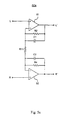
- All-pass filter 15 includes three cascaded single pole all-pass filters 251, 252, 253. Isolating each pole to a separate stage minimizes sensitivity to component variation.
- the individual single pole filters 251-253 should be configured according to well known techniques such that resultant three-pole filter 250 has pole time constants of 46 ⁇ s, 67 ⁇ s and 254 ⁇ s. It is to be understood that a filter utilizing second or higher order sections may used in order to reduce the number of required op-amps. Further, second order filter sections allow for complex pole conjugate pairs. However, such second or higher order filter sections are more sensitive to component variation.
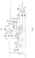
- FIG. 16 The preferred embodiment of the present invention is illustrated in Figure 16.
- the operation of stereo/mono enhancement system 260 is based upon the topology of Figure 13 and, accordingly, the discussion of the topology of Figure 13 is equally applicable to system 260.
- the left input signal L is inverted by op-amp 270 and associated resistors R60 and R61, while the right input signal R is inverted by op-amp 272 and associated resistors R70 and R71.
- This filtered signal is summed with the inverted left input signal L and the pseudo-stereo signal (synthesized by filter 250) at op-amp 271 to produce the left output signal L' output.
- Op-amp 275 subtracts the left output signal L' from the sum of the left L and right R input signals.
- Switches SW4 and SW5 allow system 260 to operate in one of three possible modes. If switch SW4 connects line 277 to ground via resistor R65, the stereo enhancement filter, e.g., the B(s) function, is disabled. When switch SW5 connects line 278 to ground, thereby disabling the pseudo-stereo synthesis function of filter 250, e.g., function C(s), system 260 will operate in a bypass mode. In this mode, the left L and right R input signals appear unmodified as left L' and right R' output signals, respectively. If, on the other hand, switch SW4 connects line 277 to line 276, the stereo enhancement filter B(s) is enabled. The operating mode of system 260 will now depend upon the position of switch SW5.
- the stereo enhancement filter e.g., the B(s) function
- switch SW5 now connects line 278 to ground, thereby disabling the pseudo-stereo synthesis function C(s), system 260 operates in a stereo-only mode. If, however, switch SW5 connects filter 250 to line 278, thereby enabling the pseudo-stereo synthesis function C(s), system 260 operates in a dual stereo/mono mode and will spatially enhance both types of input signals.
- the switching between bypass and stereo/mono enhancement modes via switch SW4 exhibits relatively low switching noise due to the low-pass filtering function of capacitor C50.
- the switching of switch SW5 may cause a discontinuity in the output signals.
- such a discontinuity is tolerable in most applications since the gain of the pseudo-stereo signal on line 278 is fairly low as compared to that of the stereo signals.
- the discontinuity may be minimized using well known zero-crossing switching techniques, or by replacing switch SW5 with a variable gain element controlled by a switching ramp signal.
- K 1 should be chosen such that K 1 ⁇ 2C 0 .
- K 1 is equal to 0.4.
- the K 1 coefficient is one such degree of freedom which can be chosen according to convenience. The above constraint on K 1 is recommended for the sake of dynamic signal range in order prevent the output of op-amp 273 from saturating with maximum input signals on both input channels.
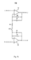
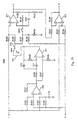
- a stereo/mono system 280 is disclosed below and illustrated in Figure 17 which operates in accordance with the topology of Figure 14. Accordingly, the discussion above with respect to the topology of Figure 14 is equally applicable to stereo/mono system 280, where the left L' and right R' output signals are related to the left L and right R inputs signals according to Equation (11).
- the stereo enhancement portion of system 280 is performed by op-amps 293, 294 and their respective associated capacitor C60 and resistors R86-R91, and thus implements the B(s) transfer function in a manner identical to stereo enhancement system 70 of Figure 6.
- Pseudo-stereo enhancement is combined with stereo enhancement by summing the pseudo-stereo signal with the left input signal L before stereo enhancement is performed, as is discussed below.
- Op-amp 290 and associated resistors R80-R81 sum and then scale by one-half the left L and right R inputs signals in order to extract the monophonic component (L+R) of the input source.
- resistors R80 and R81 should be of equal value.
- This sum signal is filtered by filter 250 according to the C(s) transfer function to synthesize a pseudo-stereo signal.
- This pseudo-stereo signal is then summed with the left input signal L by op-amp 292 and associated resistors R82-R85.
- System 280 includes two switches SW4 and SW5 which allow system 280 to switch, in a manner identical to that of system 260 of Figure 16, between bypass, stereo-only enhancement, and stereo/mono enhancement modes.
- switch SW5 connects line 295 to ground
- the operating mode of system 280 is determined by position of switch SW4. If switch SW4 connects lines 296 and 297, system 280 operates in stereo-only mode. If switch SW4 connect lines 296 and 298, system 280 operates in bypass mode.
- System 280 operates in stereo/mono mode when switch SW4 connects lines 296, 297 and switch SW5 connects line 295 to the output of filter 250.
- system 280 as compared to system 260 is achieved by using both the inverting and non-inverting modes of the op-amps therein. Although utilizing both modes of the op-amps as such may adversely affect sound quality, any such degradation in acoustic quality will be slight and well within the performance requirements of many applications.
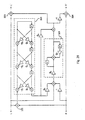
- FIG. 14 The topology of Figure 14 can be implemented in an even simpler design allowing attenuation of the input signals.
- a stereo/mono enhancement system 300a is disclosed below and illustrated in Figure 18 which requires only four op-amps.
- the input signals L and R are scaled by a factor K 2 .
- K 2 The selection of an appropriate value of K 2 involves consideration of two factors as will be discussed shortly.
- the pseudo-stereo portion of system 300a is formed by op-amps 310 and 311 and their associated resistors R100-R108 and capacitors C70-C72.
- Op-amp 310 first sums the left L and right R input signals, thereby extracting the monophonic component, and then filters this sum according to a single-pole all-pass filter.
- Op-amp 311 forms the core of a second order all-pass filter which also divides the sum signal by a factor 1+K 3 . Although somewhat dependent upon the pole frequencies, the value of K 3 should generally be close to unity in order to minimize sensitivity to component variation.
- Op-amps 312 and 313 form the stereo enhancement portion of system 300a and operate in a manner similar to stereo enhancement system 70 of Figure 6.
- Resistors R109-R113 allow D 0 to vary between B 0 + 1 and 1.
- Resistor R119 matches the attenuation of the sum signal path to the rest of the circuit.
- System 300a includes two switches SW4 and SW5 which allow system 300a to operate in either bypass, stereo only enhancement, or stereo/mono enhancement mode as previously described with respect to systems 260 and 280.
- the selection of component values in system 300a is dictated by application requirements and component types.
- the factors K 2 and K 3 can be selected to minimize the component sensitivity of the second order all-pass filter as well as to adjust the overall signal attenuation level. These two factors are constrained as follows:
- K 2 and K 3 are equal to 0.667 and 0.25, respectively.
- Time constants ⁇ 1 , ⁇ 2 and ⁇ 3 can be any permutation of recommended time constants for the C(s) function poles.
- Resistors R110-R113 provide more flexibility than may be needed for a given set of parameters. For instance, if a maximum value of D 0 is desired, then R111 should be omitted. If, on the other hand, D 0 is desired to equal 1, then R113 should be omitted. The complete set is shown for the sake of generality. It should be noted that the system 300a attenuates the input signals in all modes of operation, including bypass. Thus, the sum of output signals L' and R' will be the sum of input signals L and R multiplied by some constant factor.
- System 300a of Figure 18 may be modified to have no signal attenuation by slightly compromising the stereo enhancement transfer function B(s).
- the resultant structure, embodied as stereo/mono enhancement system 300b, is illustrated in Figure 19.
- System 300b is identical to and operates in the same manner as system 300a of Figure 18 except for the deletion of resistor R 119 and the addition of resistors R120-R121.
- R109 R110 R120 R121
- the error factor K 4 Although it is desirable for the error factor K 4 to be as small as possible, minimizing K 4 must be balanced with practicality of either maximizing resistors R111-R113 or minimizing resistors R120-R121. Applicant has found that a value of 0.1 for K 4 is fairly easily realized and produces a sound quality virtually indistinguishable from systems operating without such an error factor. This result may be objectively verified by considering that the error factor K 4 comprises a significant portion of the B' (s) transfer function only at higher frequencies and, even then, constitutes only a small fraction of the output signal power.
- FIG. 12 illustrates a complete data flow diagram for a DSP implementation based upon the topology of Figure 12.
- Block 320 forms a three-stage all-pass filter, which is equivalent to the C(s) transfer function normalized to a unity magnitude gain.
- Block 321 performs the B(s) transfer function.
- Multiplier factor g 5 accounts for the factor C 0 which is not present in the all-pass filter block 320.
- multiplier factor g 4 is scaled by C 0 . Note that gain multiplications can be rearranged in the signal flow without affecting functionality.
- the multiplier factors should be chosen as follows:
- This implementation thus requires only seven multiplier coefficients and only five delay storage elements.
- the architecture of the particular DSP used may require modifications to the signal flow diagram of Figure 20. For instance, if the DSP uses fixed-point arithmetic with a small word size, scaling might be required to avoid saturation at nodes such as those at the output of block 321 and the output of adder 322.
- multiply-accumulate operations are as economical to implement as are simple addition or multiplication, it may be advantageous to rearrange the multiplication operations so as to pair with addition operations.
Abstract
Description
- The present invention relates to a system for enhancing an acoustic image comprising first and second input channels and to a method for enhancing an acoustic image.
- US-A-4,910,778 discloses a system for enhancing an acoustic image comprising first and second input channels wherein means for processing said first and second input channels to produce a first output channel and means for combining the first output channel and the first and second input channels to produce a second output channel, wherein said first and second output channels are indicative of a spatially enhanced signal.
- In US-A-5,425,106 an integrated circuit for use as a building block for enhancing audio performance by providing group delay to various frequency components of signals is disclosed. This circuit is configured as a two-channel stereo device and can be cascaded for monaural applications.
- It is impossible to achieve the same degree of channel separation in a typical two loud-speaker stereo system that is possible with a pair of headphones. In such a stereo syste, acoustic signals arriving at a listener's ear from the left and right loud-speakers which are in phase tend to add, while those which are out of phase tend to cancel one another. This phenomena, known as speaker crosstalk, degrades the perceived spatial and directional qualities of the acoustic image. Further, since speaker crosstalk is a function of the geometry of the interfering wavefronts resulting from the intersection of the left and right acoustic signals, the effects of speakers crosstalk are dependent upon the location of the listener relative to the positions of the left and right speakers. That is, the effects of crosstalk as perceived at one location may be different from those perceived at another location. This positional dependence of crosstalk gives rise to the so-called "dead spots" and "sweet spots" a listener experiences when moving across a listening area.
- It is theoretically possible to cancel crosstalk by enhancing the stereo signals as a function of the particular positions of the speakers and the dynamic position of the listener. In practice, however, such cancellation is impossible to achieve, since the particular arrangement of a listener's speakers and the dynamic position of the listener cannot be predicted. Numerous stereo enhancement systems have been disclosed recently which attempt to compensate for this positional dependence of crosstalk by enhancing the (L-R), or difference, component and the (L+R), or sum, component of the stereo signals. Such systems, however, are relatively complex and expensive to implement.
- Further, many of the conventional stereo enhancement systems fail to effectively address the monophonic aspects of stereo signals. For instance, it is desirable in a stereo enhancement system to retain compatibility with monophonic receivers, that is, receivers which receive only the modified sum (L+R) component of the stereo signal. Receiving only the modified sum component without the ability to extract the spatial effects encoded into the difference signal results in an undesirable degradation of the original monophonic acoustic image.
- In addition, since many of the presently broadcast and recorded acoustic images include both stereo and monophonic sources, it is also desirable for a stereo enhancement system to not only spatially enhance monophonic acoustic images but also to have the ability to smoothly and automatically transition between stereo signal enhancement and monophonic signal enhancement.
- The above object is solved by a system in accordance with features of claim 1 and furthermore is solved by a method for enhancing an acoustic image in accordance with the features of claim 17.
- Further embodiments of the system and of the method are claimed in the subclaims.
-
- Figure 1a is block diagram illustrating a conventional lattice signal flow topology;
- Figure 1b is block diagram illustrating a conventional shuffle signal flow topology;
- Figure 2a is a block diagram illustrating a conventional sum-invariant signal flow topology;
- Figure 2b is a block diagram illustrating a sum-invariant topology of a stereo enhancement system in accordance with the present invention;
- Figures 3a and 3b are block diagrams illustrating other sum-invariant topologies in accordance with the present invention;
- Figure 4 is a schematic diagram of a stereo enhancement system in accordance with one embodiment of the present invention;
- Figures 5a, 5b, 6, and 7 are schematic diagrams of stereo enhancement systems in accordance with other embodiments of the present invention;
- Figures 8a and 8b are block diagrams illustrating conventional pseudo-stereo topologies;
- Figures 9a and 9b are block diagrams illustrating pseudo-stereo enhancement topologies in accordance with the present invention;
- Figures 10a, 10b, 11a, 11b, 12, 13, and 14 are block diagrams illustrating stereo/mono enhancement topologies in accordance with the present invention;
- Figure 15 is a schematic diagram illustrating an all-pass filter utilized in some embodiments of the present invention;
- Figures 16-19 are schematic diagrams of stereo/mono enhancement systems in accordance with the present invention; and
- Figure 20 is a block diagram of a topology for implementing some of the stereo/mono topologies of the present invention in a digital signal processor.
-
- It is to be understood that in the detailed discussion that follows, components common to the various embodiments and drawing figures are appropriately labelled with the same notations.
- Before discussing aspects of the present invention in detail, it is necessary to mention several important underlying principles. First, audio enhancement systems should be channel symmetric in order to preserve the centering of the original stereo signal. That is, the left and right channels of the audio signal should be identically processed such that a reversing of the inputs to the audio enhancement system would not effect the operation of the system.
- Channel-symmetric audio enhancement systems are typically implemented using either a lattice topology or a shuffle topology. Figure 1a illustrates the signal flow in a lattice topology, where L and R represent the left and right channel input signals respectively, and L' and R' represent the left and right output signals respectively. In such a lattice topology, each of the output signals is a sum of its respective input signal times a linear transfer function S(s) and the opposite input signal times a linear transfer function A(s). That is:
- Figure 1b illustrates the signal flow in a shuffle topology, where the output signals L' and R' are determined as follows:
- The transfer functions associated with the lattice and shuffle topologies of Figures 1a and 1b, respectively, are related to one another as follows:
- Further, it is desirable for an audio enhancement system to be sum invariant so as to be compatible with monophonic receivers. A sum invariant topology is that which the sum, or (L+R), component of the stereo signal is not altered such that the sum of the left and right input signals L, R equals the sum of the left and right output signals, L', R', as expressed below:
- The lattice topology of Figure 1a is sum-invariant, where the transfer functions S(s) and A(s) are related as follows:
- The shuffle topology of Figure 1b can be made sum-invariant by constraining transfer function P(s) such that:
- Applicant has found that in some instances a sum-invariant topology such as that shown in Figure 2a may offer a more efficient implementation of a stereo enhancement system. Referring to Figure 2a, the right signal R is inverted at inverter 21 and combined with the left input signal L at summing element 20 to produce a difference signal (L-R), which is then processed through a filter 22 having a transfer function B(s). The processed difference signal (L-R) is summed with the original left input signal L at summing element 23 to produce the left output signal L'. The processed difference signal (L-R) is inverted at inverter 24 and summed with the original right input signal R at summing element 25 to produce the right output signal R'. The relationship between the input signals L, R and output signals L', R' may be expressed as follows:
- The transfer function B(s) is related to the transfer function A(s) used in the lattice topology illustrated in Figure 1a as follows:
- Rearranging the sum-invariant relationship expressed in equation (2) above gives:
- It should be noted that where channel symmetry is not a requirement of the particular enhancement system, as is the case when constructing pseudo-stereo signals from a monophonic signal, the topologies of Figures 2a and 2b may be broadened as illustrated in Figures 3a and 3b, respectively. Taking the topology shown in Figure 3a, the left L and right R signals are combined and processed in function block 40 which may implement either a linear or nonlinear function. This processed signal is added to the left input signal L at summing element 41 to produce the left output signal L' and subtracted from the right input signal R via inverter 43 and summing element 42 to produce the right output signal R'. The processing performed by filter 40 may be any suitable signal shaping function of one or both of the input signals L, R.
- Referring to Figure 3b, the processing function of filter 45 may be any suitable signal shaping function of one or both of the two input signals L, R. The output signal of filter 45 is provided as the left output signal L', while the right output signal R' is produced by subtracting the left output signal L' from the sum (L+R) of the input signals.
- The shuffle topology (Figure 1b) is generally preferred over the lattice topology (Figure 1a) since the shuffle topology requires only two filters 13-14, where the lattice topology requires four filters 1-4. Nevertheless, Applicant has found that the lattice topology allows for a simpler circuit implementation of a stereo enhancement system.
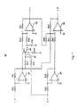
- Figure 4 shows a stereo enhancement system 50 in accordance with one embodiment of the present invention. Enhancement system 50, the design of which stems from the lattice topology of Figure 1a, requires only two op-amps 51, 52. The left input signal L is provided to the positive input of op-amp 51 and to the negative input of op-amp 52 via resistor R3, while the right input signal R is provided to the positive input of op-amp 52 and to the negative input of op-amp 51 via resistor R1. Op-amps 51 and 52, which are configured as a leaky integrator, respectively combine the left L and right R input signals as follows:
- Since the top and bottom halves of enhancement system 50 are symmetric, the values of resistors R1, R2, and capacitor C1 may in some embodiments be equal to the values of R3, R4 and capacitor C2, respectively. The values for the above-mentioned resistors and capacitors may, in actual embodiments, vary depending upon the operating characteristics of the selected op-amp, noise and input impedance considerations, and cost and size restrictions of discrete capacitors C1 and C2, as is well understood in the art. In a preferred embodiment, op-amps 51 and 52 are low noise audio-grade op-amps such as the TL074, available from Texas Instruments.
- In contrast to some conventional audio enhancement systems, enhancement system 50 of Figure 4 does not boost or otherwise alter the high-frequency portions of the difference (L-R) signal, i.e., those portions above approximately 1100 Hz. As a result, the embodiment of Figure 4 achieves a superior balance between centered and off-centered acoustic images in the source signal than do those conventional systems which provide more power to the high-frequencies of the difference (L-R) signal. It should also be noted that the embodiment of Figure 4 does not alter the sum (L+R) signal, thereby preserving monophonic acoustic images and retaining compatibility with monophonic receivers. Although contrary to numerous prior teachings of crosstalk cancellation which suggest modifying the sum component, Applicant feels that the relatively small acoustic advantages realized from modifying the sum signal are outweighed by the benefits of sum-invariance, i.e., retaining monophonic compatibility.
- The operation of enhancement system 50 of Figure 4 may be also be described in terms of the shuffle topology of Figure 1b and the sum-invariant based topologies of Figures 2a, 2b. In the case of a shuffle topology, the transfer functions N(s) and P(s) are of the form:
- The virtual short between the inputs of op-amps 51 and 52 allows the negative inputs of respective op-amps 51 and 52 to connected together via a resistor R11, as shown in Figure 5a, thereby resulting in the elimination of one resistor. Enhancement system 60a of Figure 5a operates in a manner similar to that of Figure 4 and, accordingly, those components common to the embodiments of Figures 4 and 5a are similarly labelled. The simpler design of enhancement system 60a also allows the left and right input signals to be directly coupled to the positive inputs of op-amps 51 and 52, respectively. As a result, enhancement system 60a desirably exhibits a high input impedance. Resistors R2 and R4 must be equal and capacitors C1 and C2 must be equal. The values of A0 and τP are determined as follows:
- In yet another embodiment, a switch SW1 may be added in series with resistor R11 as shown in Figure 5b. The resultant enhancement system 60b may thus switch between an enhancement mode, in which the left and right input signals L, R are enhanced as described above to produce enhanced left and right output signals L', R', and a bypass mode, in which the left and right input signals L, R pass unmodified through enhancement system 60 and appear as left and right output signals L', R'. Switch SW1 may be any suitable switching device. The low-pass filter nature of op-amps 51 and 52 desirably prevents instantaneous voltage changes between input signals and output signals. Thus, when switching between modes, the left and right output signals L', R' will exponentially converge to their respective input signals L, R as a function of the time constant τp, thereby resulting in smooth switching transitions between modes. Accordingly, complex switching techniques which minimize switching noise, such as zero-crossing switching techniques, are unnecessary.
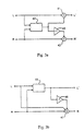
- As mentioned earlier, the sum-invariant topologies depicted in Figures 2a and 2b may allow for an improved circuit implementation of stereo enhancement system in accordance with the present invention. Referring to Figure 6, the design of enhancement system 70 is based upon the sum-invariant topology illustrated in Figure 2b. The left output signal L' is produced through op-amp 71 and its associated feedback elements R21 and C20, which operate as a leaky integrator, from the sum of the left and right input signals (L+R). The right output signal R' is constructed according to equation (5), i.e., op-amp 72 sums the left output signal L' with the input signal sum (L+R) to produce the right output signal R'. In order to ensure proper summing at op-amp 72, resistors R23 and R24 should be of equal value, and resistors R22 and R25 should be of equal value. Note that the sum-invariant design of enhancement system 70 requires only one capacitor C20, as opposed to the two capacitors required in the embodiments of Figures 4 and 5. Switch SW2 allows the enhancement system 70 to switch between enhancement and bypass modes as previously described with respect to Figure 5.
- Enhancement system 70 operates according to the aforementioned B(s) transfer function,
- The B0 and τp parameters are determined as follows:
- Preferably, the values of B0 and τp are approximately 3.125 and 600µs, respectively. With the exception of the above mentioned constraints, the values of the resistors contained in enhancement system 70 may vary depending upon desired operating characteristics. Note that since capacitor C20 prevents the voltage at the negative input of op-amp 71 from changing instantaneously, voltage continuity of the left output signal L' is preserved when switching between modes via switch SW2. Thus, when enhancement system 70 is switched from enhancement to bypass mode, op-amp 71 acts as a voltage follower, with the output voltage offset by the voltage across C20. Capacitor C20 will gradually discharge through the parallel combination of resistors R20 and R21. When switch SW2 switches from bypass to enhancement mode, capacitor C20 is exponentially charged, thereby preserving the voltage continuity of the output and minimizing switching impulse energy. Resistors R20, R21 and capacitor C20 determine the time constant of exponential transients caused when switching between modes. Line 74 serves primarily as a shunt to prevent parasitic coupling between lines 73 and 75 from producing any unwanted residual effect in bypass mode. Where not necessary, line 74 may be removed such that capacitor C20 discharges only through R21.
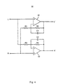
- The embodiments described above with reference to Figures 4-6 employ a minimum number of op-amps in order to minimize implementation cost. The distortion and fidelity associated with enhancement system 70 may be improved by modifying enhancement system 70 to employ op-amps which operate only in an inverting mode. Such a modification is illustrated in Figure 7 as stereo enhancement system 80. Op-amp 81 and resistors R30, R31 invert the left input signal L, and op-amp 83 and resistors R38, R39 invert the R input signal, where R30 = R31 and R38 = R39. Op amp 84 and associated resistors R40-R43 produce the right output signal R' according to the sum-invariant constraint of Equation (5). Resistors R40-R43 should be of equal value to ensure proper summing at op-amp 84. Op-amp 82 and associated capacitor C30 and resistors R32-R37 produce the left output signal L' according to Equations (3) and (7), where the B0 and τp parameters, which are preferably 3.125 and 600 µs, respectively, govern the selection of other component values as follows:
- As stated earlier with reference to other embodiments, the precise values of the components employed in enhancement system 80 may vary depending upon desired operating characteristics. Resistors R32, R33 and R36 are related radiometrically to R37. Switch SW3 switches enhancement system 80 between enhancement and bypass modes. When SW3 connects lines 85 and 86, enhancement system 80 enters enhancement mode and operates as described above. When switch SW3 connects line 85 to ground via resistor R34, enhancement system 80 enters bypass mode. In this mode, op-amp 82 operates as an inverter and provides a left output signal L' equal to the left input signal L. It follows, then, that the L' signal and inverted L signal cancel at op-amp 84 such that the right output signal R' is equal to the right input signal R. Capacitor C30 helps to ensure voltage continuity between modes as discussed previously. When switching from enhancement to bypass mode, C30 completely discharges to ground through the parallel combination of resistors R36 and R34. While not necessary to the operation of system 80, the path to ground through resistor R34 helps to eliminate parasitic coupling. When switching from bypass to spatialization mode, C30 gradually charges in the normal course of operation.
- The embodiments described above with reference to Figures 4-7 are advantageous over prior enhancement systems based upon the shuffle topology in that the voltages of the internal nodes of the embodiments of Figures 4-7 will not exceed the maximum input voltage or maximum output voltage. Conversely, in shuffle topology based enhancement systems, the internally generated sum (L+R) and difference (L-R) signal voltages may be twice that of the maximum input signals, thereby requiring either (1) halving the voltage range of the input signals or (2) dividing the sum (L+R) and difference (L-R) signals by a factor of two. The former alternative undesirably limits the range of compatible input signal levels, while the latter alternative undesirably reduces the signal to noise ratio (by as much as 6 dB).
- The above described embodiments can easily be implemented with a digital signal processor. The pole and zero frequencies used in the above transfer functions are a small fraction of typical audio sample rates. Thus, the bilinear transformation can be used to derive a discrete time version. As is well understood in the art of digital signal processing, the bilinear transformation is a useful approximation which relates the s-plane of the Laplace transform to the discrete-time z-plane as follows:
- Using a sample rate of 44.1 kHz and the parameter values disclosed above, the above expression reduces as follows:
- An efficient approach to computing a spatially enhanced data sample can be obtained by using the signal flow illustrated in the topology of Figure 2a in conjunction with the above-denoted B(z). It is to be understood that a particular topology which yields the greatest efficiency in an analog implementation does not necessarily yield the most efficient digital implementation. For instance, in analog implementations, the number of inverting and summing operations significantly affects implementation cost, while the number of signals added or inverted in a particular operation has only a slight impact upon implementation cost. In a digital implementation, on the other hand, the total number of summing operations is a function of the total number of signals so summed minus the number of summing operations. Further, negations typically impose no additional overhead. As a result, the sum-invariant topology of Figure 2a is probably preferable over that of Figure 2b for the digital implementation of stereo enhancement systems in accordance with the present invention. It should be further noted that the most economical DSP implementation may depend upon the architecture of the particular digital signal processor used. Nonetheless, a sum-invariant based DSP implementation will usually be superior to those based upon either the lattice or shuffle topologies. It is to be understood, however, that circuit designs based upon each of the above described topologies can be easily mapped from the analog domain to the discrete-time digital domain.
- In accordance with other embodiments of the present invention, a system is disclosed which spatially enhances not only stereo signals but also monophonic signals in a manner similar to those previously described. A complete understanding of these other embodiments requires an appreciation of some basic principles used in the conversion of monophonic signals to pseudo-stereo signals.
- It is well understood that a pseudo-stereo signal may be synthesized from a monophonic signal (e.g., a signal in which the right and left channels are identical) by spatially "placing" the sound towards either the left or right channel in a selective manner dependent upon the frequency of the monophonic input signal. Such a synthesis may be accomplished by first modifying the input signal and then adding and subtracting this modified signal to and from, respectively, the original input signal to produce left and right channels which are different.
- For instance, Figures 8a and 8b illustrate two common topologies for such synthesis. Referring first to Figure 8a, the monophonic input signal M is routed through an all-pass filter 90 having a transfer function C(s). The output of filter 90 is alternately added to, via summing element 92, and subtracted from, via inverter 91 and summing element 93, attenuated replicas of the original input signal M to produce left L' and right R' pseudo stereo signals, respectively. The relationship between output signals L', R' and the input signal M may be expressed as follows:
- Typically, the time constants τ1-τn will, in actual implementations, naturally occur in complex conjugate pairs. The constant C0 determines the "depth" of the pseudo-stereo effect. This effect is maximized when C0 is equal to either 0.5 or -0.5. At these values of C0, certain frequencies will appear exclusively in one of the output channels. The sign of C0 is somewhat arbitrary, since reversing the sign is merely equivalent to swapping the L' and R' channel outputs of Figure 8a. The number of crossover points, that is, the number of particular frequencies at which the energies in the left and right channels are equal, is determined by the order of C(s). Note that the gain element 94 of Figure 8a is not essential, but rather has been included to aid in understanding embodiments of the present invention which later follow. This also allows the Figure 8a topology to meet the following criterion:
- which implies that the topology will be sum-invariant if the M input signal is constructed by summing left L and right R input signals.
- The topology illustrated in Figure 8b, which operates in a manner identical to that of the topology of Figure 8a, may provide a more economical implementation in certain cases.
- The pseudo-stereo topologies illustrated in Figures 8a and 8b suffer from a couple of drawbacks. If C0 is chosen to achieve maximum depth, i.e., equal to either 0.5 or -0.5, the contrast between left and right channels may be too extreme and lead to a "deaf-in-one-ear" phenomenon. This undesirable effect may be minimized by increasing the order of the all-pass filter transfer function C(s). Such a remedy, however, results in an increased implementation cost. This deaf-in-one-ear phenomenon may minimized by simply reducing the value of C0 in order to provide a more acoustically plausible spread of the input signal. Reducing C0, however, will cause a decrease in the phase difference between the left and right channels and, therefore, will diminish the perceived spaciousness of the acoustic image. In other words, reducing C0 undesirably allows speaker crosstalk to cancel out-of-phase energy in the bass frequencies.
- In accordance with the present invention, Applicant has found that the deaf-in-one-ear phenomenon may be minimized, without significantly diminishing spaciousness, in one of two ways. In the first approach, a modified C(s) transfer function may be implemented, where C(s) is re-defined as:
- In the second and preferred approach, one of the pseudo-stereo synthesis topologies illustrated in Figures 8a and 8b may be cascaded with the stereo enhancement systems described above in accordance with the present invention, as illustrated in Figure 9a. In this stereo/mono enhancement topology, filter 100 creates the pseudo-stereo left channel on line 103 while inverter 101 and summing element 102 create the pseudo-stereo right channel on line 104. A stereo enhancement system 107 enhances these pseudo-stereo channel signals to produce left and right output signal L', R' on lines 105 and 106, respectively. System 107 may be any suitable one of the stereo enhancement systems previously described in accordance with the present invention. Note that since each of previously described embodiments of stereo enhancement systems are channel-symmetric, the particular channel assignment to system 107 is arbitrary. It is to be understood that although the pseudo-stereo portion of the topology of Figure 9a is based upon the topology of Figure 8b, it may in other embodiments be based upon the topology of Figure 8a.
- Using the sum-invariant relationship R' = L + R - L', the stereo/mono enhancement topology of Figure 9a may be simplified to that of Figure 9b, where transfer function D(s) represents the enhancement function performed by system 107 in the topology of Figure 9a. The outputs L' and R' are related to input M as follows:
- D(s) is defined as follows:
- It follows that the monophonic input signal M is related to the left L' and right R' output signals as follows:
- Since the pseudo-stereo (L-R) difference signal tends to be more sensitive to excessive bass frequency boost than does a typical stereophonic (L-R) difference signal, the boost associated with a pseudo-stereo enhancement system should be somewhat lower than that of a pure stereo enhancement system such as those described earlier. Applicant has chosen D0 to be equal to just over half of 2B0+1, i.e., approximately 4.5. The time constant τp is, as mentioned previously, approximately equal to 600 µs. The particular order of transfer function C(s) involves a tradeoff between superior sound quality (higher order) and implementation cost (lower order). In a preferred embodiment to be described shortly, C(s) is implemented in a manner so as to have three poles and zeroes, an order which Applicant believes achieves a satisfactory compromise between sound enhancement and implementation cost. The preferred time constants for the three poles and zeroes are 46µs, 67µs and 254µs, respectively, which are all real. Applicant has found that a value of 0.2 for the constant C0 results in an optimal tradeoff between deep separation and shallow subtlety.
- In typical audio applications, the nature of the received signal (i.e., whether stereophonic or monophonic) is usually not known. In some instances, such as FM radio transmissions, the received signal may vary between a stereophonic and monophonic nature. Thus, it would be desirable to provide a mechanism capable of not only enhancing both the stereo and mono signals but also of smoothly switching between such modes. In accordance with the present invention, a pseudo-stereo synthesis system 131 may be cascaded with stereo enhancement system 126 as illustrated the topology in Figure 10a. It is to be understood that stereo enhancement system 126 may be any of the previously described stereo enhancement systems. Where the input signal is of a monophonic nature, e.g., where the left input signal L is identical to the right input signal R, the topology of Figure 10a will operate in a manner identical to that of the topology of Figure 9a. The gain of a variable gain element 121 may be varied between zero and unity in response to an external control signal (not shown) such as a stereo blend signal received from an FM stereo decoder or a stereophonic source detection circuit or even a user control. When gain element 121 is set to have a gain of zero, the pseudo-stereo synthesis portion 131 is effectively disabled such that the operation of the topology of Figure 10a is determined solely by stereo enhancement system 126. Thus, variable gain element 121 allows for the dynamic control of the depth of the pseudo-stereo synthesis effect. Note that it is possible, with the appropriate choice of parameters, to fix the gain of variable gain element 121 at unity for all signal sources.
- In practice, most stereo sources contain sufficient out-of-phase channel information to effectively mask the pseudo-stereo effect, while any monophonic components present will benefit from the pseudo-stereo effect. Thus, if a stereo signal contains very little spatialized information, i.e., a minimal difference (L-R) signal, the pseudo-stereo component will dominate the stereo component. Thus, for such a stereo signal, the pseudo-stereo effect will spatially enhance the corresponding acoustic image. Where variable gain element 121 has unity gain, the inputs and outputs of the topology of Figure 10a may be related to one another as follows:
- If variable gain element 121 is used to dynamically switch between modes, i.e., between enabling and disabling pseudo-stereo synthesis portion 131, certain measures will need to be taken to ensure low switching noise. For instance, the gain of variable gain element 121 should varied at such a rate so as not to introduce significant high-frequency energy into the acoustic signals.
- In the topology of Figure 10a, both pseudo-stereo input signals (synthesized from a monophonic input signal via portion 131) and stereophonic input signals are filtered via stereo enhancement system 126 and, thus, are processed according to the same previously disclosed parameters associated with the transfer function B(s). Since, however, pseudo-stereo signals generated from monophonic signals are different from pure stereophonic signals, it would be advantageous for each of such signals to be spatially enhanced according to different parameters while simultaneously enabling a blending of the two enhancement effects.
- Thus, in accordance with another embodiment of the present invention, a pseudo-stereo synthesis system 140 is cascaded to the output lines 143, 144 of stereo enhancement system 126 as illustrated in the topology of Figure 10b. In this topology, the stereo enhancement parameters and thus the spatially enhancing effect of stereo enhancement circuit 126 will affect only stereophonic signals received on input lines 141, 142 (since monophonic signals do not contain a (L-R) difference component, monophonic input signals received on lines 141, 142 pass unmodified through stereo enhancement system 126). These unmodified monophonic input signals are processed in pseudo-stereo synthesis system 140 by a filter 147 having a transfer function of C(s)D(s), where C(s) and D(s) synthesize and spatially enhance, respectively, the pseudo-stereo signal. The topology of Figure 10b operates, in all other respects, in a manner identical to that of the topology of Figure 10a. Where variable gain element is set to unity gain, the inputs and outputs of the topology of Figure 10b may be related to one another as follows:
- In a preferred implementation, D(s) is of the form disclosed in Equation (9), where D0 and τp are approximately 4.5 and 600 µs, respectively.
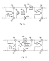
- The topologies of Figures 10a and 10b may be modified so as to operate according to shuffle-style topologies as illustrated in Figures 11a and 11b, respectively. The topology of Figure 11a uses the same enhancement filter 167, having a transfer function of N(s), in processing both stereo and pseudo-stereo signals. That is, like the topology of Figure 10a, the topology of Figure 11a uses the same parameters in spatially enhancing both stereo and pseudo-stereo signals. The function N(s) is of the form previously described with respect to Figure 1b. Pseudo-stereo filter 164 operates according to the previously described transfer function C(s) multiplied by a factor of 2. Assuming that Equation (8) remains valid, the relationship between the inputs and outputs of the topology of Figure 11a may be expressed according to Equation (10). In a manner similar to the topologies of Figures 10a and 10b, variable gain element 121 may be either manually or automatically controlled to accommodate a variety of types of input signals, or set to unity gain and still handle most monophonic and stereo input signals.
- The topology of Figure 11b, a modified version of the topology of Figure 11a, utilizes distinct spatial enhancement parameters for stereo and pseudo-stereo signals in a manner similar to that described with respect to the topology of Figure 10b. In the topology of Figure 11b, unlike that of Figure 11a, the pseudo-stereo signal is synthesized and spatially enhanced by filter 147 according to transfer functions C(s) and D(s), respectively, and summed with the enhanced stereo signal generated by filter 167 according to transfer function N(s). Again, transfer functions C(s), D(s), and N(s) are of the respective forms previously described.
- Note that these topologies are advantageously sum-invariant notwithstanding the asymmetrical nature of pseudo-stereo transfer function C(s). It should also be noted that since monophonic input signals do not contain a (L-R) difference component, when such a monophonic signal is provided as an input to the topologies of Figures 11a and 11b, the (L-R) difference signal path (created by summing element 160) will contain no signal. Thus, the coupling of the (L+R) sum signal to the difference signal path via filter 164 and summing element 166 is vital in the construction of the left output signal L'.
- Since the above topologies are sum-invariant, they may be modified to operate according to the sum-invariant topologies of Figures 3a and 3b, thereby resulting in more simplified and more cost-effective implementations. Further, Applicant has found that greater simplification may be achieved by setting the pole time constant of the D(s) transfer function equal to that of the B(s) transfer function. In this manner, the D(s) transfer function need not be explicitly implemented while advantageously providing distinct enhancement parameters for stereo and pseudo-stereo signals. Thus, the filter which would have otherwise implemented C(s)D(s) now need only implement C(s), thereby allowing for the elimination of one pole-determining capacitor. Note that this simplification results in the elimination of one delay element in digital implementations.
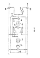
- The resultant simplified topologies derived from the topologies of Figures 11a and 11b are illustrated in Figures 12 and 13, respectively. In the topology of Figure 12, summing elements 208 and 209, along with inverter 210, replicate the style of the sum-invariant topology of Figure 3a. Summing element 200, variable gain element 210, filter 202 having a transfer function C(s), and gain element 205, construct the pseudo-stereo signal. The magnitude of the signal output from filter 202 will, to a significant degree, determine the magnitude of the pseudo-stereo synthesis at those frequencies significantly above the pole of transfer function B(s), i.e., significantly above 265 Hz. The magnitude of the signal output from gain element 205 will determine the magnitude of the pseudo-stereo synthesis at DC. Thus, the effect of the previously described transfer function D(s) is emulated by the addition of signals at summing elements 204 and 207. The constant D0 of the emulated transfer function D(s) is preferably approximately 4.5 and may be set as follows:
- Note that in the topology of Figure 12, it is possible to control the gain at any point along a given signal path and achieve identical results. For typical analog implementations, the inputs of a summing network are usually multiplied by some gain factor. Thus, there are several ways to ensure that the magnitude of signals provided to summing elements 204 and 207 from filter 202 are independently adjustable; so utilizing gain element 205 is only one of such ways. The stereo enhancement portion of the topology of Figure 12 operates in a manner similar to that of the topology of Figures 2a. Thus, the form and parameter values for transfer function B(s) and C(s) are preferably as stated previously.
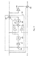
- The topology of Figure 13 operates in a manner nearly identical to that of Figure 12 with one notable exception. Inverter 229 and summing elements 227 and 228 are configured so as to replicate the sum-invariant style topology of Figure 3b. Thus, other than the function of summing element 227, components within block 45 of the topology of Figure 13 operate in an identical manner and perform the same function as those components in block 40 of the topology of Figure 12.
- Where it is desired to have distinct enhancement pole time constants for each of the pseudo-stereo synthesis and stereo signal enhancement functions, the topologies of Figures 12 and 13 may be modified by eliminating the signal path passing through gain element 205 and altering filter 202 to have a transfer function C(s)D(s).
- The topologies of Figures 12 and 13 may be further simplified, and thus implemented at a reduced cost, by slightly sacrificing the spatial attribute of the pseudo-stereo signal. Such a simplified topology is illustrated in Figure 14, where the role of filters 246, 247 and summing element 248 may be performed in analog implementations by a single op-amp configured as a leaky integrator such as, for instance, op-amp 51 of stereo enhancement system 50 of Figure 4. The left L' and right R' output signals and left L and right R input signals in the topology of Figure 14 are related to one another as expressed by Equation (11), where gain element 241 is set to unity. However, the emulated D(s) transfer function will be of the form:
- Where G243 is zero, D(s) will achieve a maximum bass frequency enhancement. Accordingly, where G243 equals unity, there will be no bass frequency enhancement. G243 should be chosen such that:
- Although different applications may require slightly different parameter values, G243 should preferably be zero in order to effect the maximum depth possible which, in turn, implies that D0 should be approximately 4.125. The preferred form and associated parameter values for transfer functions B(s) and C(s) are as stated previously. In a manner similar to that of the topologies of Figures 12 and 13, the signals provided to summing elements 244 and 245 may be independently scaled.
- Implementing the above described stereo/mono enhancement topologies will, in actual embodiments, require an all-pass filter such as the conventional three-pole all-pass filter 250 illustrated in Figure 15. All-pass filter 15 includes three cascaded single pole all-pass filters 251, 252, 253. Isolating each pole to a separate stage minimizes sensitivity to component variation. Note that the first filter 251 should be designed such that R50 = R51. Filter 251 will have a transfer function H(s) and an associated pole time constant τ:
- In the preferred embodiments of the stereo/mono enhancement system that follow, the individual single pole filters 251-253 should be configured according to well known techniques such that resultant three-pole filter 250 has pole time constants of 46µs, 67µs and 254µs. It is to be understood that a filter utilizing second or higher order sections may used in order to reduce the number of required op-amps. Further, second order filter sections allow for complex pole conjugate pairs. However, such second or higher order filter sections are more sensitive to component variation.
- The preferred embodiment of the present invention is illustrated in Figure 16. The operation of stereo/mono enhancement system 260 is based upon the topology of Figure 13 and, accordingly, the discussion of the topology of Figure 13 is equally applicable to system 260. Note that with the exception of op-amps 256 of all-pass filter 250, each of the op-amps in system 260 of Figure 16 operates in an inverting mode for reasons discussed earlier. The left input signal L is inverted by op-amp 270 and associated resistors R60 and R61, while the right input signal R is inverted by op-amp 272 and associated resistors R70 and R71. These two inverted signals are scaled and summed at op-amp 273 to extract the monophonic signal component which is then delayed by all-pass filter 250 to produce a pseudo-stereo signal. When switch SW5 connects the output of filter 250 to line 278, the pseudo-stereo signal is summed with the inverted left input signal L and non-inverted right input signal R at the node common to resistors R62-R64. When switch SW4 connects lines 276 and 277, this sum signal is low-pass filtered by capacitor C50 according to the B(s) transfer function. This filtered signal is summed with the inverted left input signal L and the pseudo-stereo signal (synthesized by filter 250) at op-amp 271 to produce the left output signal L' output. Op-amp 275 subtracts the left output signal L' from the sum of the left L and right R input signals.
- Switches SW4 and SW5 allow system 260 to operate in one of three possible modes. If switch SW4 connects line 277 to ground via resistor R65, the stereo enhancement filter, e.g., the B(s) function, is disabled. When switch SW5 connects line 278 to ground, thereby disabling the pseudo-stereo synthesis function of filter 250, e.g., function C(s), system 260 will operate in a bypass mode. In this mode, the left L and right R input signals appear unmodified as left L' and right R' output signals, respectively. If, on the other hand, switch SW4 connects line 277 to line 276, the stereo enhancement filter B(s) is enabled. The operating mode of system 260 will now depend upon the position of switch SW5. If switch SW5 now connects line 278 to ground, thereby disabling the pseudo-stereo synthesis function C(s), system 260 operates in a stereo-only mode. If, however, switch SW5 connects filter 250 to line 278, thereby enabling the pseudo-stereo synthesis function C(s), system 260 operates in a dual stereo/mono mode and will spatially enhance both types of input signals.
- As discussed with respect to system 80 of Figure 7, the switching between bypass and stereo/mono enhancement modes via switch SW4 exhibits relatively low switching noise due to the low-pass filtering function of capacitor C50. The switching of switch SW5 may cause a discontinuity in the output signals. However, such a discontinuity is tolerable in most applications since the gain of the pseudo-stereo signal on line 278 is fairly low as compared to that of the stereo signals. In applications where such a discontinuity is unacceptable, the discontinuity may be minimized using well known zero-crossing switching techniques, or by replacing switch SW5 with a variable gain element controlled by a switching ramp signal.
- The selection of appropriate values for the components contained in system 260 may vary depending on the particular application, the desired operating characteristics, and the types of components used. Note, however, that the following constraints should be met in order to realize the benefits of system 260. First, the resistors associated with summing/inverting op-amps 270, 272 and output op-amp 271 should be chosen such that:
- Next, resistor R69 and capacitor C50 should chosen such that the product of their values is as follows:
- After selecting an appropriate value for resistor R69, the remaining resistor values associated with op-amp 271 are determined as follows:
- The resistors associated with op-amp 273 should satisfy the following ratios:
- In another embodiment, a stereo/mono system 280 is disclosed below and illustrated in Figure 17 which operates in accordance with the topology of Figure 14. Accordingly, the discussion above with respect to the topology of Figure 14 is equally applicable to stereo/mono system 280, where the left L' and right R' output signals are related to the left L and right R inputs signals according to Equation (11). The emulated D(s) transfer function is of the form previously stated with reference to the topology of Figure 14, where D0 is fixed at a maximum value such that:
- The stereo enhancement portion of system 280 is performed by op-amps 293, 294 and their respective associated capacitor C60 and resistors R86-R91, and thus implements the B(s) transfer function in a manner identical to stereo enhancement system 70 of Figure 6. Pseudo-stereo enhancement is combined with stereo enhancement by summing the pseudo-stereo signal with the left input signal L before stereo enhancement is performed, as is discussed below.
- Op-amp 290 and associated resistors R80-R81 sum and then scale by one-half the left L and right R inputs signals in order to extract the monophonic component (L+R) of the input source. Note that resistors R80 and R81 should be of equal value. This sum signal is filtered by filter 250 according to the C(s) transfer function to synthesize a pseudo-stereo signal. This pseudo-stereo signal is then summed with the left input signal L by op-amp 292 and associated resistors R82-R85. The gain of left input signal through op-amp 292 is unity, while the gain of the synthesized pseudo-stereo signal through op-amp 292 may be adjusted according to the desired depth of the pseudo-stereo effect. Accordingly, values for resistors R82-R85 should be chosen as follows:
- System 280 includes two switches SW4 and SW5 which allow system 280 to switch, in a manner identical to that of system 260 of Figure 16, between bypass, stereo-only enhancement, and stereo/mono enhancement modes. Thus, when switch SW5 connects line 295 to ground, the operating mode of system 280 is determined by position of switch SW4. If switch SW4 connects lines 296 and 297, system 280 operates in stereo-only mode. If switch SW4 connect lines 296 and 298, system 280 operates in bypass mode. System 280 operates in stereo/mono mode when switch SW4 connects lines 296, 297 and switch SW5 connects line 295 to the output of filter 250. As discussed above in reference to previous embodiments, the values of components contained in system 280 may vary depending upon design, component and performance considerations. However, the following constraints should be satisfied in order to realize the benefits of the embodiment of Figure 17:
- The simpler design and lower implementation cost of system 280 as compared to system 260 is achieved by using both the inverting and non-inverting modes of the op-amps therein. Although utilizing both modes of the op-amps as such may adversely affect sound quality, any such degradation in acoustic quality will be slight and well within the performance requirements of many applications.
- The topology of Figure 14 can be implemented in an even simpler design allowing attenuation of the input signals. In accordance with another embodiment of the present invention, a stereo/mono enhancement system 300a is disclosed below and illustrated in Figure 18 which requires only four op-amps. The input signals L and R are scaled by a factor K2. The selection of an appropriate value of K2 involves consideration of two factors as will be discussed shortly.
- The pseudo-stereo portion of system 300a is formed by op-amps 310 and 311 and their associated resistors R100-R108 and capacitors C70-C72. Op-amp 310 first sums the left L and right R input signals, thereby extracting the monophonic component, and then filters this sum according to a single-pole all-pass filter. Op-amp 311 forms the core of a second order all-pass filter which also divides the sum signal by a factor 1+K3. Although somewhat dependent upon the pole frequencies, the value of K3 should generally be close to unity in order to minimize sensitivity to component variation. Op-amps 312 and 313 form the stereo enhancement portion of system 300a and operate in a manner similar to stereo enhancement system 70 of Figure 6. Resistors R109-R113 allow D0 to vary between B0 + 1 and 1. Resistor R119 matches the attenuation of the sum signal path to the rest of the circuit.
- System 300a includes two switches SW4 and SW5 which allow system 300a to operate in either bypass, stereo only enhancement, or stereo/mono enhancement mode as previously described with respect to systems 260 and 280.
- The selection of component values in system 300a is dictated by application requirements and component types. The factors K2 and K3 can be selected to minimize the component sensitivity of the second order all-pass filter as well as to adjust the overall signal attenuation level. These two factors are constrained as follows:

- In a preferred embodiment, K2 and K3 are equal to 0.667 and 0.25, respectively. The component values used in the pseudo-stereo portion should satisfy the following constraints:


- Time constants τ1, τ2 and τ3 can be any permutation of recommended time constants for the C(s) function poles. The component values used in the stereo enhancement portion should satisfy the following constraints:

- Resistors R110-R113 provide more flexibility than may be needed for a given set of parameters. For instance, if a maximum value of D0 is desired, then R111 should be omitted. If, on the other hand, D0 is desired to equal 1, then R113 should be omitted. The complete set is shown for the sake of generality. It should be noted that the system 300a attenuates the input signals in all modes of operation, including bypass. Thus, the sum of output signals L' and R' will be the sum of input signals L and R multiplied by some constant factor.
- It should be noted that most of the systems and topologies described above may be modified to have a gain other than unity by ensuring that the L and R signal paths have an equivalent attenuation or gain. Such modifications will become apparent to those skilled in the art after reading this disclosure.
- System 300a of Figure 18 may be modified to have no signal attenuation by slightly compromising the stereo enhancement transfer function B(s). The resultant structure, embodied as stereo/mono enhancement system 300b, is illustrated in Figure 19. System 300b is identical to and operates in the same manner as system 300a of Figure 18 except for the deletion of resistor R 119 and the addition of resistors R120-R121. In order to ensure unity gain in bypass mode and no attenuation in the stereo only and stereo/mono enhancement modes, the following constraint should be met:
- System 300b will operate according to a modified enhancement transfer function B'(s) which from the previously defined B(s) transfer function as follows:

- Although it is desirable for the error factor K4 to be as small as possible, minimizing K4 must be balanced with practicality of either maximizing resistors R111-R113 or minimizing resistors R120-R121. Applicant has found that a value of 0.1 for K4 is fairly easily realized and produces a sound quality virtually indistinguishable from systems operating without such an error factor. This result may be objectively verified by considering that the error factor K4 comprises a significant portion of the B' (s) transfer function only at higher frequencies and, even then, constitutes only a small fraction of the output signal power.
- All of the above described stereo/mono systems may be mapped into the discrete-time digital signal processing domain using the bilinear transform mentioned earlier. A digital implementation is quite useful to allow a user to dynamically adjust parameter values. By way of example, the topology of Figure 12 may be digitally implemented as follows. Figure 20 illustrates a complete data flow diagram for a DSP implementation based upon the topology of Figure 12. Block 320 forms a three-stage all-pass filter, which is equivalent to the C(s) transfer function normalized to a unity magnitude gain. Block 321 performs the B(s) transfer function. Multiplier factor g5 accounts for the factor C0 which is not present in the all-pass filter block 320. Similarly, multiplier factor g4 is scaled by C0. Note that gain multiplications can be rearranged in the signal flow without affecting functionality. In the preferred implementation the multiplier factors should be chosen as follows:
- g1 = -0.991495
- g2 = 0.894378
- g3 = -0.392830
- g4 = 1.440000
- g5 = 0.200000
- g6 = 0.057956
- g7 = 0.962908
-
- This implementation thus requires only seven multiplier coefficients and only five delay storage elements. Note that the architecture of the particular DSP used may require modifications to the signal flow diagram of Figure 20. For instance, if the DSP uses fixed-point arithmetic with a small word size, scaling might be required to avoid saturation at nodes such as those at the output of block 321 and the output of adder 322. In architectures in which multiply-accumulate operations are as economical to implement as are simple addition or multiplication, it may be advantageous to rearrange the multiplication operations so as to pair with addition operations. Such issues, as well as the DSP implementation of specific embodiments of the present invention, are well understood in the art.
Claims (18)
- A system for enhancing an acoustic image comprising first and second input channels (L,R), characterized by:wherein the means (46, 47) for combining said first output channel (L') with a sum of first and second input channels (L,R) comprises a summing circuit (47) subtracting (46) said first output channel (L') from a sum of said first and second input channels therefore producing said second output channel (R').filtering and combining means (45) having in input first and second input channels (L,R) and producing a first output channel (L'); andcombining means (46, 47) combining said first output channel (L') with a sum of said first and second input channels (L,R) and producing a second output channel (R') , where said first and second output channels (L',R') are indicative of a spatially enhanced signal,
- The system of claim 1 wherein the means for combining comprises a summing circuit (45), said summing circuit adding said first output channel (L') with inverted first and second input channels, respectively, to produce said second output channel (R').
- The system of claim 1 wherein the means for filtering comprises an integrator.
- The system of claim 3 wherein said integrator comprises:a first op-amp (71) having first and second input terminals and an output terminal, said first input terminal of said first op-amp (71) coupled to receive said first input channel, said second input terminal of said first op-amp (71) coupled to receive said second input channel, said output terminal of said first op-amp (71) providing said first output channel; anda feedback network (R21, C20) coupled between said output terminal and second input terminal of said first op-amp (71).
- The system of claim 4, wherein said summing circuit comprises a second op-amp (72) having first and second input terminals and an output terminal, said first input terminal of said second op-amp (72) coupled to receive said first and second input channels, said second input terminal of said second op-amp (72) coupled to receive said first output channel, said output terminal of said second op-amp (72) providing said second output channel.
- The system of claim 1 wherein said means for filtering and combining further comprises:summing means (200) summing said first and second input channels to produce a sum signal;phase-shifting means (202) phase-shifting said sum signal using an all-pass filter to produce an enhanced sum signal;combining means (244) combining said enhanced sum signal with said first input channel to produce an intermediate signal; andfiltering means (246) filtering said intermediate signal using a low-pass filter to produce said first output channel.
- The system of claim 6 wherein said summing means (200) and said phase-shifting means (202) comprise:a first op-amp (310) having non-inverting and inverting terminals each coupled to receive said first and second input channels and having an output terminal; anda second op-amp (311) having non-inverting and inverting terminals coupled to said output terminal of said first op-amp (310), said second op-amp (311) providing said enhanced sum signal at an output terminal thereof.
- The system of claim 7 wherein said combining means (244) combining said enhanced sum signal with said first input channel comprises a third op-amp (312) having a non-inverting terminal coupled to receive said first input channel and said enhanced sum signal and having an inverting terminal coupled to receive said second input channel, said third op-amp (312) providing said first output channel at an output terminal thereof.
- The system of claim 8 wherein said combining means (244) combining said first output channel and said first and second input channels comprise a fourth op-amp (313) having a non-inverting terminal coupled to receive said first and second input channels and having an inverting terminal coupled to receive said first output channel, said fourth op-amp (313) providing said second output channel at an output terminal thereof.
- The system of claim 9 further comprising a first capacitor (C70) having a first plate coupled to said non-inverting terminal of said first op-amp (310) and having a second plate coupled to a first node (GND), said first capacitor (C70) facilitating a first order all-pass filter.
- The system of claim 10 further comprising a feedback network (R106, C71, C72) coupled between said inverting terminal and said output terminal of said second op-amp (311), said feedback network implementing an all-pass filter.
- The system of claim 11 wherein said feedback network (R106, C71, C72) implements a second order all-pass filter.
- The system of claim 11 wherein said feedback network further comprises:a resistor (R106) having a first end coupled to said inverting terminal of said second op-amp (311);a first capacitor (C71) having a first plate coupled to said first end of said resistor (R106); anda second capacitor (C72) having a first plate coupled to a second plate of said first capacitor (C71) and having a second plate coupled to a second end of said resistor (R106) and to said output terminal of said second op-amp (311).
- The system of claim 9 further comprising a feedback network comprising:a first resistor (R114) coupled between said inverting input and said output terminals of said third op-amp (312); anda capacitor (C73) coupled in parallel with said first resistor (R114).
- A method for enhancing an acoustic image comprising first and second input channels to produce an enhanced acoustic image, said method comprising the steps of:wherein said combining step to produce said second output channel comprises subtracting said first output channel from a sum of said first and second input channels.filtering and combining said first and second input channels to produce a first output channel; andcombining said first output channel and said first and second input channels to produce a second output channel, where said first and second output channels comprise said enhanced acoustic image,
- The method of claim 15 wherein the combining step comprises summing said first output channel with inverted first and second input channels to produce said second output channel.
- The method of claim 15 wherein the filtering step utilizes an integrator.
- The method of claim 15 wherein the filtering and combining step further comprises:summing said first and second input channels to produce a sum signal;phase-shifting said sum signal using an all-pass filter to produce an enhanced sum signal;combining said enhanced sum signal with said first input channel to produce an intermediate signal; andfiltering said intermediate signal using a low-pass filter to produce said first output channel.
Applications Claiming Priority (3)
| Application Number | Priority Date | Filing Date | Title |
|---|---|---|---|
| US491138 | 1995-06-15 | ||
| US08/491,138 US5692050A (en) | 1995-06-15 | 1995-06-15 | Method and apparatus for spatially enhancing stereo and monophonic signals |
| PCT/US1996/009240 WO1997000594A1 (en) | 1995-06-15 | 1996-06-13 | Method and apparatus for spatially enhancing stereo and monophonic signals |
Publications (2)
| Publication Number | Publication Date |
|---|---|
| EP0776593A1 EP0776593A1 (en) | 1997-06-04 |
| EP0776593B1 true EP0776593B1 (en) | 2004-09-01 |
Family
ID=23950946
Family Applications (1)
| Application Number | Title | Priority Date | Filing Date |
|---|---|---|---|
| EP96921325A Expired - Lifetime EP0776593B1 (en) | 1995-06-15 | 1996-06-13 | Method and apparatus for spatially enhancing stereo and monophonic signals |
Country Status (11)
| Country | Link |
|---|---|
| US (3) | US5692050A (en) |
| EP (1) | EP0776593B1 (en) |
| JP (1) | JP3420247B2 (en) |
| KR (1) | KR100305407B1 (en) |
| AT (1) | ATE275317T1 (en) |
| AU (1) | AU701204B2 (en) |
| BR (1) | BR9606444A (en) |
| CA (1) | CA2196779C (en) |
| DE (1) | DE69633264D1 (en) |
| TW (1) | TW312889B (en) |
| WO (1) | WO1997000594A1 (en) |
Families Citing this family (49)
| Publication number | Priority date | Publication date | Assignee | Title |
|---|---|---|---|---|
| US5661808A (en) | 1995-04-27 | 1997-08-26 | Srs Labs, Inc. | Stereo enhancement system |
| US5692050A (en) * | 1995-06-15 | 1997-11-25 | Binaura Corporation | Method and apparatus for spatially enhancing stereo and monophonic signals |
| US5912975A (en) * | 1995-06-30 | 1999-06-15 | Philips Electronics North America Corp | Method and circuit for creating phantom sources using phase shifting circuitry |
| JP3740670B2 (en) * | 1997-05-20 | 2006-02-01 | 株式会社河合楽器製作所 | Stereo sound image magnifier |
| SE512719C2 (en) * | 1997-06-10 | 2000-05-02 | Lars Gustaf Liljeryd | A method and apparatus for reducing data flow based on harmonic bandwidth expansion |
| US6947564B1 (en) * | 1999-01-11 | 2005-09-20 | Thomson Licensing | Stereophonic spatial expansion circuit with tonal compensation and active matrixing |
| SE9903553D0 (en) | 1999-01-27 | 1999-10-01 | Lars Liljeryd | Enhancing conceptual performance of SBR and related coding methods by adaptive noise addition (ANA) and noise substitution limiting (NSL) |
| AU763506B2 (en) | 1999-04-22 | 2003-07-24 | Cybergnost Ltd & Co Kg | Device for recording a thermo-optical image of the female breast |
| EP1177707B1 (en) * | 1999-05-13 | 2004-09-15 | Thomson Licensing S.A. | Centralizing of a spatially expanded stereophonic audio image |
| JP2000341798A (en) * | 1999-05-28 | 2000-12-08 | Sanyo Electric Co Ltd | Device for expanding stereophonic sound image |
| JP2003505810A (en) * | 1999-07-20 | 2003-02-12 | コーニンクレッカ フィリップス エレクトロニクス エヌ ヴィ | Record carrier for carrying stereo and data signals |
| EP1232672A1 (en) | 1999-11-25 | 2002-08-21 | Embracing Sound Experience AB | A method of processing and reproducing an audio stereo signal, and an audio stereo signal reproduction system |
| SE0001926D0 (en) * | 2000-05-23 | 2000-05-23 | Lars Liljeryd | Improved spectral translation / folding in the subband domain |
| US7660424B2 (en) * | 2001-02-07 | 2010-02-09 | Dolby Laboratories Licensing Corporation | Audio channel spatial translation |
| GB0106269D0 (en) * | 2001-03-14 | 2001-05-02 | Auntiegravity Ltd | Improvements in noise cancellation |
| JP4371621B2 (en) * | 2001-03-22 | 2009-11-25 | 新日本無線株式会社 | Surround playback circuit |
| US8605911B2 (en) | 2001-07-10 | 2013-12-10 | Dolby International Ab | Efficient and scalable parametric stereo coding for low bitrate audio coding applications |
| SE0202159D0 (en) * | 2001-07-10 | 2002-07-09 | Coding Technologies Sweden Ab | Efficientand scalable parametric stereo coding for low bitrate applications |
| US7752266B2 (en) | 2001-10-11 | 2010-07-06 | Ebay Inc. | System and method to facilitate translation of communications between entities over a network |
| EP1423847B1 (en) | 2001-11-29 | 2005-02-02 | Coding Technologies AB | Reconstruction of high frequency components |
| US6735314B2 (en) * | 2002-05-13 | 2004-05-11 | Thomson Licensing S.A. | Expanded stereophonic circuit with tonal compensation |
| US7564982B1 (en) * | 2002-06-25 | 2009-07-21 | Phantom Technologies, Inc. | Two channel audio surround sound circuit |
| SE0202770D0 (en) | 2002-09-18 | 2002-09-18 | Coding Technologies Sweden Ab | Method of reduction of aliasing is introduced by spectral envelope adjustment in real-valued filterbanks |
| FI118370B (en) | 2002-11-22 | 2007-10-15 | Nokia Corp | Equalizer network output equalization |
| SE527062C2 (en) * | 2003-07-21 | 2005-12-13 | Embracing Sound Experience Ab | Stereo sound processing method, device and system |
| US7623669B2 (en) * | 2005-03-25 | 2009-11-24 | Upbeat Audio, Inc. | Simplified amplifier providing sharing of music with enhanced spatial presence through multiple headphone jacks |
| SE530180C2 (en) * | 2006-04-19 | 2008-03-18 | Embracing Sound Experience Ab | Speaker Device |
| US8619998B2 (en) * | 2006-08-07 | 2013-12-31 | Creative Technology Ltd | Spatial audio enhancement processing method and apparatus |
| US8639782B2 (en) | 2006-08-23 | 2014-01-28 | Ebay, Inc. | Method and system for sharing metadata between interfaces |
| US8363842B2 (en) * | 2006-11-30 | 2013-01-29 | Sony Corporation | Playback method and apparatus, program, and recording medium |
| US20080165976A1 (en) * | 2007-01-05 | 2008-07-10 | Altec Lansing Technologies, A Division Of Plantronics, Inc. | System and method for stereo sound field expansion |
| US8073153B2 (en) * | 2007-02-21 | 2011-12-06 | Knowles Electronics, Llc | System and method for engaging in conversation while using an earphone |
| EP1988746A3 (en) * | 2007-03-31 | 2009-09-09 | Sony Deutschland Gmbh | Method for outputting audio signals and audio decoder |
| EP2197105A1 (en) * | 2007-09-27 | 2010-06-16 | Yamaha Corporation | Electronic device |
| US8121318B1 (en) * | 2008-05-08 | 2012-02-21 | Ambourn Paul R | Two channel audio surround sound circuit with automatic level control |
| US20100027799A1 (en) * | 2008-07-31 | 2010-02-04 | Sony Ericsson Mobile Communications Ab | Asymmetrical delay audio crosstalk cancellation systems, methods and electronic devices including the same |
| US8577065B2 (en) * | 2009-06-12 | 2013-11-05 | Conexant Systems, Inc. | Systems and methods for creating immersion surround sound and virtual speakers effects |
| US8571232B2 (en) * | 2009-09-11 | 2013-10-29 | Barry Stephen Goldfarb | Apparatus and method for a complete audio signal |
| US8259960B2 (en) * | 2009-09-11 | 2012-09-04 | BSG Laboratory, LLC | Phase layering apparatus and method for a complete audio signal |
| US8553892B2 (en) * | 2010-01-06 | 2013-10-08 | Apple Inc. | Processing a multi-channel signal for output to a mono speaker |
| CH703501A2 (en) * | 2010-08-03 | 2012-02-15 | Stormingswiss Gmbh | Device and method for evaluating and optimizing signals on the basis of algebraic invariants. |
| JP5556673B2 (en) * | 2011-01-11 | 2014-07-23 | 株式会社Jvcケンウッド | Audio signal correction apparatus, audio signal correction method and program |
| JP5776223B2 (en) * | 2011-03-02 | 2015-09-09 | ソニー株式会社 | SOUND IMAGE CONTROL DEVICE AND SOUND IMAGE CONTROL METHOD |
| US8913752B2 (en) * | 2012-03-22 | 2014-12-16 | Htc Corporation | Audio signal measurement method for speaker and electronic apparatus having the speaker |
| WO2013179100A1 (en) * | 2012-06-01 | 2013-12-05 | Nokia Coporation | Stereo audio output, associated apparatus and methods |
| WO2014144968A1 (en) | 2013-03-15 | 2014-09-18 | O'polka Richard | Portable sound system |
| US10149058B2 (en) | 2013-03-15 | 2018-12-04 | Richard O'Polka | Portable sound system |
| USD740784S1 (en) | 2014-03-14 | 2015-10-13 | Richard O'Polka | Portable sound device |
| WO2022035730A1 (en) * | 2020-08-13 | 2022-02-17 | Owlet Baby Care, Inc. | Multi-channel common-mode coupled ac gain amplifier |
Family Cites Families (80)
| Publication number | Priority date | Publication date | Assignee | Title |
|---|---|---|---|---|
| US2836662A (en) * | 1954-08-18 | 1958-05-27 | Emi Ltd | Electrical sound transmission systems |
| US3670106A (en) * | 1970-04-06 | 1972-06-13 | Parasound Inc | Stereo synthesizer |
| US4096360A (en) * | 1975-09-27 | 1978-06-20 | Victor Company Of Japan, Ltd. | Multichannel record disc reproducing system |
| US4087629A (en) * | 1976-01-14 | 1978-05-02 | Matsushita Electric Industrial Co., Ltd. | Binaural sound reproducing system with acoustic reverberation unit |
| US4118599A (en) * | 1976-02-27 | 1978-10-03 | Victor Company Of Japan, Limited | Stereophonic sound reproduction system |
| JPS52125301A (en) * | 1976-04-13 | 1977-10-21 | Victor Co Of Japan Ltd | Signal processing circuit |
| US4053711A (en) * | 1976-04-26 | 1977-10-11 | Audio Pulse, Inc. | Simulation of reverberation in audio signals |
| US4149036A (en) * | 1976-05-19 | 1979-04-10 | Nippon Columbia Kabushikikaisha | Crosstalk compensating circuit |
| DE2640254A1 (en) * | 1976-09-03 | 1978-03-09 | Manfred Schunke | Stereophonic reproduction system - subjects channel signals to delay, phase shift and frequency change and cross-mixes signals with originals |
| JPS53114201U (en) * | 1977-02-18 | 1978-09-11 | ||
| JPS53116101A (en) * | 1977-03-18 | 1978-10-11 | Matsushita Electric Ind Co Ltd | Acoustic reproducer |
| JPS5832840B2 (en) * | 1977-09-10 | 1983-07-15 | 日本ビクター株式会社 | 3D sound field expansion device |
| US4239939A (en) * | 1979-03-09 | 1980-12-16 | Rca Corporation | Stereophonic sound synthesizer |
| US4309570A (en) * | 1979-04-05 | 1982-01-05 | Carver R W | Dimensional sound recording and apparatus and method for producing the same |
| JPS5931279B2 (en) * | 1979-06-19 | 1984-08-01 | 日本ビクター株式会社 | signal conversion circuit |
| US4388494A (en) * | 1980-01-12 | 1983-06-14 | Schoene Peter | Process and apparatus for improved dummy head stereophonic reproduction |
| JPS56111400A (en) * | 1980-02-06 | 1981-09-03 | Mitsubishi Electric Corp | Sound field expanding apparatus |
| US4308423A (en) * | 1980-03-12 | 1981-12-29 | Cohen Joel M | Stereo image separation and perimeter enhancement |
| US4355203A (en) * | 1980-03-12 | 1982-10-19 | Cohen Joel M | Stereo image separation and perimeter enhancement |
| US4356349A (en) * | 1980-03-12 | 1982-10-26 | Trod Nossel Recording Studios, Inc. | Acoustic image enhancing method and apparatus |
| JPS575499A (en) * | 1980-06-12 | 1982-01-12 | Mitsubishi Electric Corp | Acoustic reproducing device |
| JPS575500A (en) * | 1980-06-12 | 1982-01-12 | Mitsubishi Electric Corp | Acoustic reproducing device |
| JPS5742300A (en) * | 1980-08-27 | 1982-03-09 | Toshiba Corp | Sound image extension and playback device |
| JPS5773599A (en) * | 1980-10-24 | 1982-05-08 | Pioneer Electronic Corp | Stereophonic reproducing device |
| US4394535A (en) * | 1981-03-09 | 1983-07-19 | Rca Corporation | Split phase stereophonic sound synthesizer |
| US4479235A (en) * | 1981-05-08 | 1984-10-23 | Rca Corporation | Switching arrangement for a stereophonic sound synthesizer |
| DE3118704A1 (en) * | 1981-05-12 | 1982-12-02 | Bruens, Dieter, 5030 Hürth | Playback synthesizer |
| US4415768A (en) * | 1981-05-28 | 1983-11-15 | Carver R W | Tuning apparatus and method |
| JPS5830299A (en) * | 1981-08-18 | 1983-02-22 | Toshiba Corp | Sound field enlarging device |
| US4495637A (en) * | 1982-07-23 | 1985-01-22 | Sci-Coustics, Inc. | Apparatus and method for enhanced psychoacoustic imagery using asymmetric cross-channel feed |
| US5412731A (en) * | 1982-11-08 | 1995-05-02 | Desper Products, Inc. | Automatic stereophonic manipulation system and apparatus for image enhancement |
| US4567607A (en) * | 1983-05-03 | 1986-01-28 | Stereo Concepts, Inc. | Stereo image recovery |
| DE3579732D1 (en) * | 1984-04-09 | 1990-10-25 | Pioneer Electronic Corp | SOUND FIELD IMPROVEMENT SYSTEM. |
| US4594730A (en) * | 1984-04-18 | 1986-06-10 | Rosen Terry K | Apparatus and method for enhancing the perceived sound image of a sound signal by source localization |
| JPS60172500U (en) * | 1984-04-23 | 1985-11-15 | パイオニア株式会社 | Digital audio playback device |
| WO1986001363A1 (en) * | 1984-08-10 | 1986-02-27 | Matsushita Electric Industrial Co., Ltd. | Apparatus for reproducing sound field |
| JPS61187500A (en) * | 1985-02-15 | 1986-08-21 | Pioneer Electronic Corp | Sound field enlarging circuit for stereo reproducing |
| US4700389A (en) * | 1985-02-15 | 1987-10-13 | Pioneer Electronic Corporation | Stereo sound field enlarging circuit |
| IT1185706B (en) * | 1985-09-12 | 1987-11-12 | Sgs Microelettronica Spa | STEREO BASE NON-RECURSIVE EXPANSION SYSTEM FOR STEREOFONIC SOUND SYSTEMS |
| JPS62163499A (en) * | 1986-01-13 | 1987-07-20 | Fujitsu Ten Ltd | Reverberation unit for stereo acoustic device |
| GB2187068B (en) * | 1986-02-25 | 1988-12-14 | Microbourne Limited | Sound reproduction system |
| US4748669A (en) * | 1986-03-27 | 1988-05-31 | Hughes Aircraft Company | Stereo enhancement system |
| JPS63224599A (en) * | 1987-03-13 | 1988-09-19 | Asa Plan:Kk | Stereo processing unit |
| US5034983A (en) * | 1987-10-15 | 1991-07-23 | Cooper Duane H | Head diffraction compensated stereo system |
| US4975954A (en) * | 1987-10-15 | 1990-12-04 | Cooper Duane H | Head diffraction compensated stereo system with optimal equalization |
| US5136651A (en) * | 1987-10-15 | 1992-08-04 | Cooper Duane H | Head diffraction compensated stereo system |
| US4893342A (en) * | 1987-10-15 | 1990-01-09 | Cooper Duane H | Head diffraction compensated stereo system |
| US4910779A (en) * | 1987-10-15 | 1990-03-20 | Cooper Duane H | Head diffraction compensated stereo system with optimal equalization |
| US4910778A (en) * | 1987-10-16 | 1990-03-20 | Barton Geoffrey J | Signal enhancement processor for stereo system |
| US4837824A (en) * | 1988-03-02 | 1989-06-06 | Orban Associates, Inc. | Stereophonic image widening circuit |
| US4841572A (en) * | 1988-03-14 | 1989-06-20 | Hughes Aircraft Company | Stereo synthesizer |
| US4831652A (en) * | 1988-05-05 | 1989-05-16 | Thomson Consumer Electronics, Inc. | Stereo expansion circuit selection switch |
| EP0357034A3 (en) * | 1988-08-30 | 1991-08-07 | Nec Corporation | Audio signal processing system performing balance control in both amplitude and phase of audio signal |
| JP2522529B2 (en) * | 1988-10-31 | 1996-08-07 | 株式会社東芝 | Sound effect device |
| US4866774A (en) * | 1988-11-02 | 1989-09-12 | Hughes Aircraft Company | Stero enhancement and directivity servo |
| JPH03163999A (en) * | 1989-08-05 | 1991-07-15 | Matsushita Electric Ind Co Ltd | Sound reproducing device |
| CA2000955A1 (en) * | 1989-08-07 | 1991-02-07 | Lyman R. Lyon | Pipe liner and method of installation thereof |
| JPH03171900A (en) * | 1989-11-29 | 1991-07-25 | Pioneer Electron Corp | Sound field correction device for narrow space |
| US5042068A (en) * | 1989-12-28 | 1991-08-20 | Zenith Electronics Corporation | Audio spatial equalization system |
| JPH0435499A (en) * | 1990-05-31 | 1992-02-06 | Sony Corp | Sound attaching circuit |
| JP2945724B2 (en) * | 1990-07-19 | 1999-09-06 | 松下電器産業株式会社 | Sound field correction device |
| JPH04128896A (en) * | 1990-09-20 | 1992-04-30 | Casio Comput Co Ltd | Reverberation addition device |
| JPH07105999B2 (en) * | 1990-10-11 | 1995-11-13 | ヤマハ株式会社 | Sound image localization device |
| FR2677839A1 (en) * | 1991-06-14 | 1992-12-18 | Looktag Ltd | Method and device for a stereophonic sound reproduction system |
| JPH05191896A (en) * | 1992-01-13 | 1993-07-30 | Pioneer Electron Corp | Pseudo stereo device |
| US5420929A (en) * | 1992-05-26 | 1995-05-30 | Ford Motor Company | Signal processor for sound image enhancement |
| US5274708A (en) * | 1992-06-01 | 1993-12-28 | Fusan Labs, Inc. | Digital stereo sound enhancement unit and method |
| GB9211756D0 (en) * | 1992-06-03 | 1992-07-15 | Gerzon Michael A | Stereophonic directional dispersion method |
| US5278909A (en) * | 1992-06-08 | 1994-01-11 | International Business Machines Corporation | System and method for stereo digital audio compression with co-channel steering |
| US5414774A (en) * | 1993-02-12 | 1995-05-09 | Matsushita Electric Corporation Of America | Circuit and method for controlling an audio system |
| US5572591A (en) * | 1993-03-09 | 1996-11-05 | Matsushita Electric Industrial Co., Ltd. | Sound field controller |
| US5425106A (en) * | 1993-06-25 | 1995-06-13 | Hda Entertainment, Inc. | Integrated circuit for audio enhancement system |
| US5400405A (en) * | 1993-07-02 | 1995-03-21 | Harman Electronics, Inc. | Audio image enhancement system |
| US5440638A (en) * | 1993-09-03 | 1995-08-08 | Q Sound Ltd. | Stereo enhancement system |
| US5434921A (en) * | 1994-02-25 | 1995-07-18 | Sony Electronics Inc. | Stereo image control circuit |
| JP3276528B2 (en) * | 1994-08-24 | 2002-04-22 | シャープ株式会社 | Sound image enlargement device |
| US5527591A (en) * | 1994-12-02 | 1996-06-18 | Augat Inc. | Electrical contact having a particulate surface |
| US5692050A (en) * | 1995-06-15 | 1997-11-25 | Binaura Corporation | Method and apparatus for spatially enhancing stereo and monophonic signals |
| US5677957A (en) * | 1995-11-13 | 1997-10-14 | Hulsebus; Alan | Audio circuit producing enhanced ambience |
| US5724429A (en) * | 1996-11-15 | 1998-03-03 | Lucent Technologies Inc. | System and method for enhancing the spatial effect of sound produced by a sound system |
-
1995
- 1995-06-15 US US08/491,138 patent/US5692050A/en not_active Expired - Fee Related
- 1995-06-30 TW TW084106768A patent/TW312889B/zh active
-
1996
- 1996-06-13 EP EP96921325A patent/EP0776593B1/en not_active Expired - Lifetime
- 1996-06-13 AU AU62572/96A patent/AU701204B2/en not_active Ceased
- 1996-06-13 DE DE69633264T patent/DE69633264D1/en not_active Expired - Lifetime
- 1996-06-13 WO PCT/US1996/009240 patent/WO1997000594A1/en active IP Right Grant
- 1996-06-13 AT AT96921325T patent/ATE275317T1/en not_active IP Right Cessation
- 1996-06-13 BR BR9606444A patent/BR9606444A/en unknown
- 1996-06-13 JP JP50316897A patent/JP3420247B2/en not_active Expired - Fee Related
- 1996-06-13 CA CA002196779A patent/CA2196779C/en not_active Expired - Fee Related
- 1996-06-13 KR KR1019970700916A patent/KR100305407B1/en not_active IP Right Cessation
-
1997
- 1997-05-08 US US08/848,402 patent/US5883962A/en not_active Expired - Fee Related
- 1997-05-08 US US08/848,386 patent/US5850454A/en not_active Expired - Fee Related
Also Published As
| Publication number | Publication date |
|---|---|
| JPH10504170A (en) | 1998-04-14 |
| DE69633264D1 (en) | 2004-10-07 |
| EP0776593A1 (en) | 1997-06-04 |
| US5850454A (en) | 1998-12-15 |
| US5883962A (en) | 1999-03-16 |
| WO1997000594A1 (en) | 1997-01-03 |
| AU6257296A (en) | 1997-01-15 |
| AU701204B2 (en) | 1999-01-21 |
| CA2196779A1 (en) | 1997-01-03 |
| TW312889B (en) | 1997-08-11 |
| ATE275317T1 (en) | 2004-09-15 |
| JP3420247B2 (en) | 2003-06-23 |
| US5692050A (en) | 1997-11-25 |
| KR100305407B1 (en) | 2001-09-28 |
| KR970705326A (en) | 1997-09-06 |
| BR9606444A (en) | 1997-09-02 |
| CA2196779C (en) | 1999-08-03 |
| MX9701199A (en) | 1998-05-31 |
Similar Documents
| Publication | Publication Date | Title |
|---|---|---|
| EP0776593B1 (en) | Method and apparatus for spatially enhancing stereo and monophonic signals | |
| US4349698A (en) | Audio signal translation with no delay elements | |
| CN100493235C (en) | Xiafula audible signal processing circuit and method | |
| US7945054B2 (en) | Method and apparatus to reproduce wide mono sound | |
| US6173061B1 (en) | Steering of monaural sources of sound using head related transfer functions | |
| EP0965246B1 (en) | Stereo sound expander | |
| KR100410794B1 (en) | Sound image localizing device | |
| EP0865226B1 (en) | A system for improving a spatial effect of stereo sound or encoded sound | |
| KR19990041134A (en) | 3D sound system and 3D sound implementation method using head related transfer function | |
| EP1310139A2 (en) | Stereo audio processing device | |
| US6067360A (en) | Apparatus for localizing a sound image and a method for localizing the same | |
| JP3557177B2 (en) | Stereophonic device for headphone and audio signal processing program | |
| EP1968348A2 (en) | Stereophonic sound output apparatus and early reflection generation method thereof | |
| US5751817A (en) | Simplified analog virtual externalization for stereophonic audio | |
| US8107632B2 (en) | Digital signal processing apparatus, method thereof and headphone apparatus | |
| KR20010033932A (en) | Pseudo-stereophony device | |
| US8019086B2 (en) | Stereo synthesizer using comb filters and intra-aural differences | |
| KR100682492B1 (en) | Audio Player | |
| Mouchtaris et al. | Non-minimum phase inverse filter methods for immersive audio rendering | |
| MXPA97001199A (en) | Metodo and aparatoo to spaciously improve stereo phonic and monofoni signals | |
| JP3311701B2 (en) | Pseudo-stereo device | |
| Lim | Virtual loudspeaker algorithms for multiple listener immersive audio rendering | |
| KR20000052081A (en) | Stereo acoustic field expanding system of using video and reverse signal gain control |
Legal Events
| Date | Code | Title | Description |
|---|---|---|---|
| PUAI | Public reference made under article 153(3) epc to a published international application that has entered the european phase |
Free format text: ORIGINAL CODE: 0009012 |
|
| AK | Designated contracting states |
Kind code of ref document: A1 Designated state(s): AT BE CH DE DK ES FI FR GB GR IE IT LI LU MC NL PT SE |
|
| AX | Request for extension of the european patent |
Free format text: AL PAYMENT 970303;LT PAYMENT 970303;LV PAYMENT 970303;SI PAYMENT 970303 |
|
| 17P | Request for examination filed |
Effective date: 19970603 |
|
| 17Q | First examination report despatched |
Effective date: 20010404 |
|
| GRAP | Despatch of communication of intention to grant a patent |
Free format text: ORIGINAL CODE: EPIDOSNIGR1 |
|
| GRAS | Grant fee paid |
Free format text: ORIGINAL CODE: EPIDOSNIGR3 |
|
| GRAA | (expected) grant |
Free format text: ORIGINAL CODE: 0009210 |
|
| AK | Designated contracting states |
Kind code of ref document: B1 Designated state(s): AT BE CH DE DK ES FI FR GB GR IE IT LI LU MC NL PT SE |
|
| AX | Request for extension of the european patent |
Extension state: AL LT LV SI |
|
| PG25 | Lapsed in a contracting state [announced via postgrant information from national office to epo] |
Ref country code: NL Free format text: LAPSE BECAUSE OF FAILURE TO SUBMIT A TRANSLATION OF THE DESCRIPTION OR TO PAY THE FEE WITHIN THE PRESCRIBED TIME-LIMIT Effective date: 20040901 Ref country code: LI Free format text: LAPSE BECAUSE OF FAILURE TO SUBMIT A TRANSLATION OF THE DESCRIPTION OR TO PAY THE FEE WITHIN THE PRESCRIBED TIME-LIMIT Effective date: 20040901 Ref country code: IT Free format text: LAPSE BECAUSE OF FAILURE TO SUBMIT A TRANSLATION OF THE DESCRIPTION OR TO PAY THE FEE WITHIN THE PRESCRIBED TIME-LIMIT;WARNING: LAPSES OF ITALIAN PATENTS WITH EFFECTIVE DATE BEFORE 2007 MAY HAVE OCCURRED AT ANY TIME BEFORE 2007. THE CORRECT EFFECTIVE DATE MAY BE DIFFERENT FROM THE ONE RECORDED. Effective date: 20040901 Ref country code: FR Free format text: LAPSE BECAUSE OF FAILURE TO SUBMIT A TRANSLATION OF THE DESCRIPTION OR TO PAY THE FEE WITHIN THE PRESCRIBED TIME-LIMIT Effective date: 20040901 Ref country code: FI Free format text: LAPSE BECAUSE OF FAILURE TO SUBMIT A TRANSLATION OF THE DESCRIPTION OR TO PAY THE FEE WITHIN THE PRESCRIBED TIME-LIMIT Effective date: 20040901 Ref country code: CH Free format text: LAPSE BECAUSE OF FAILURE TO SUBMIT A TRANSLATION OF THE DESCRIPTION OR TO PAY THE FEE WITHIN THE PRESCRIBED TIME-LIMIT Effective date: 20040901 Ref country code: BE Free format text: LAPSE BECAUSE OF FAILURE TO SUBMIT A TRANSLATION OF THE DESCRIPTION OR TO PAY THE FEE WITHIN THE PRESCRIBED TIME-LIMIT Effective date: 20040901 Ref country code: AT Free format text: LAPSE BECAUSE OF FAILURE TO SUBMIT A TRANSLATION OF THE DESCRIPTION OR TO PAY THE FEE WITHIN THE PRESCRIBED TIME-LIMIT Effective date: 20040901 |
|
| REG | Reference to a national code |
Ref country code: GB Ref legal event code: FG4D |
|
| REG | Reference to a national code |
Ref country code: CH Ref legal event code: EP |
|
| REG | Reference to a national code |
Ref country code: IE Ref legal event code: FG4D |
|
| REF | Corresponds to: |
Ref document number: 69633264 Country of ref document: DE Date of ref document: 20041007 Kind code of ref document: P |
|
| PG25 | Lapsed in a contracting state [announced via postgrant information from national office to epo] |
Ref country code: SE Free format text: LAPSE BECAUSE OF FAILURE TO SUBMIT A TRANSLATION OF THE DESCRIPTION OR TO PAY THE FEE WITHIN THE PRESCRIBED TIME-LIMIT Effective date: 20041201 Ref country code: GR Free format text: LAPSE BECAUSE OF FAILURE TO SUBMIT A TRANSLATION OF THE DESCRIPTION OR TO PAY THE FEE WITHIN THE PRESCRIBED TIME-LIMIT Effective date: 20041201 Ref country code: DK Free format text: LAPSE BECAUSE OF FAILURE TO SUBMIT A TRANSLATION OF THE DESCRIPTION OR TO PAY THE FEE WITHIN THE PRESCRIBED TIME-LIMIT Effective date: 20041201 |
|
| PG25 | Lapsed in a contracting state [announced via postgrant information from national office to epo] |
Ref country code: DE Free format text: LAPSE BECAUSE OF FAILURE TO SUBMIT A TRANSLATION OF THE DESCRIPTION OR TO PAY THE FEE WITHIN THE PRESCRIBED TIME-LIMIT Effective date: 20041202 |
|
| PG25 | Lapsed in a contracting state [announced via postgrant information from national office to epo] |
Ref country code: ES Free format text: LAPSE BECAUSE OF FAILURE TO SUBMIT A TRANSLATION OF THE DESCRIPTION OR TO PAY THE FEE WITHIN THE PRESCRIBED TIME-LIMIT Effective date: 20041212 |
|
| LTIE | Lt: invalidation of european patent or patent extension |
Effective date: 20040901 |
|
| NLV1 | Nl: lapsed or annulled due to failure to fulfill the requirements of art. 29p and 29m of the patents act | ||
| REG | Reference to a national code |
Ref country code: CH Ref legal event code: PL |
|
| PG25 | Lapsed in a contracting state [announced via postgrant information from national office to epo] |
Ref country code: LU Free format text: LAPSE BECAUSE OF NON-PAYMENT OF DUE FEES Effective date: 20050613 Ref country code: IE Free format text: LAPSE BECAUSE OF NON-PAYMENT OF DUE FEES Effective date: 20050613 Ref country code: GB Free format text: LAPSE BECAUSE OF NON-PAYMENT OF DUE FEES Effective date: 20050613 |
|
| PG25 | Lapsed in a contracting state [announced via postgrant information from national office to epo] |
Ref country code: MC Free format text: LAPSE BECAUSE OF NON-PAYMENT OF DUE FEES Effective date: 20050630 |
|
| PLBE | No opposition filed within time limit |
Free format text: ORIGINAL CODE: 0009261 |
|
| STAA | Information on the status of an ep patent application or granted ep patent |
Free format text: STATUS: NO OPPOSITION FILED WITHIN TIME LIMIT |
|
| 26N | No opposition filed |
Effective date: 20050602 |
|
| EN | Fr: translation not filed | ||
| GBPC | Gb: european patent ceased through non-payment of renewal fee |
Effective date: 20050613 |
|
| REG | Reference to a national code |
Ref country code: IE Ref legal event code: MM4A |
|
| PG25 | Lapsed in a contracting state [announced via postgrant information from national office to epo] |
Ref country code: PT Free format text: LAPSE BECAUSE OF NON-PAYMENT OF DUE FEES Effective date: 20050201 |