EP1177707B1 - Centralizing of a spatially expanded stereophonic audio image - Google Patents
Centralizing of a spatially expanded stereophonic audio image Download PDFInfo
- Publication number
- EP1177707B1 EP1177707B1 EP00932346A EP00932346A EP1177707B1 EP 1177707 B1 EP1177707 B1 EP 1177707B1 EP 00932346 A EP00932346 A EP 00932346A EP 00932346 A EP00932346 A EP 00932346A EP 1177707 B1 EP1177707 B1 EP 1177707B1
- Authority
- EP
- European Patent Office
- Prior art keywords
- frequencies
- signal
- audio system
- treble
- bass
- Prior art date
- Legal status (The legal status is an assumption and is not a legal conclusion. Google has not performed a legal analysis and makes no representation as to the accuracy of the status listed.)
- Expired - Lifetime
Links
Images


Classifications
-
- H—ELECTRICITY
- H04—ELECTRIC COMMUNICATION TECHNIQUE
- H04S—STEREOPHONIC SYSTEMS
- H04S1/00—Two-channel systems
- H04S1/002—Non-adaptive circuits, e.g. manually adjustable or static, for enhancing the sound image or the spatial distribution
-
- H—ELECTRICITY
- H04—ELECTRIC COMMUNICATION TECHNIQUE
- H04S—STEREOPHONIC SYSTEMS
- H04S1/00—Two-channel systems
-
- H—ELECTRICITY
- H04—ELECTRIC COMMUNICATION TECHNIQUE
- H04R—LOUDSPEAKERS, MICROPHONES, GRAMOPHONE PICK-UPS OR LIKE ACOUSTIC ELECTROMECHANICAL TRANSDUCERS; DEAF-AID SETS; PUBLIC ADDRESS SYSTEMS
- H04R3/00—Circuits for transducers, loudspeakers or microphones
- H04R3/04—Circuits for transducers, loudspeakers or microphones for correcting frequency response
-
- H—ELECTRICITY
- H04—ELECTRIC COMMUNICATION TECHNIQUE
- H04S—STEREOPHONIC SYSTEMS
- H04S7/00—Indicating arrangements; Control arrangements, e.g. balance control
- H04S7/30—Control circuits for electronic adaptation of the sound field
Definitions
- Stereophonic enhancement audio systems typically process sum 'L+R and difference L-R signal components which, if not otherwise available, can be generated from a pair of left L and right R signals.
- the difference signal can be used to create a spatially broadened stereo image when reproduced through a pair of left and right loudspeakers or through a surround system.
- Boosting the level of the difference signal with respect to the sum signal can widen such a perceived sound image.
- Such processing of the difference signal includes equalization comprising both bass and treble boost.
- an increase in level in the difference signal can have undesirable effects on a person's perception of the sound.
- boosting of the difference signal in the mid-range of audio frequencies can cause a sound perception which is undesirably very sensitive to the physical location of the listener with respect to the left and right loudspeakers.
- the spatially broadened stereo image does not property localize sounds which would normally emanate from the center, such as speech from a person visually centered on a display of television or motion picture programming. This is the case whether or not the sound system includes a center loudspeaker or just left and right loudspeakers.
- U.S. Patent No. 4,229,716 discloses an amplitude equalizer circuit utilizing active components in which unidirectional functional tuning of the amplitude, bandwidth and center frequency, may each be adjusted by varying a single resistance for each parameter.
- U.S. Patent No. 4,866,744 discloses a directivity servo for controllably amplifying a stereo difference signal in response to amplitude of an input signal from one side or the other or from one channel or the other.
- the desired bass reduction in the L + R sum signal of the audio system can be accomplished by the use of a gyrator to economically synthesize an inductance.
- a gyrator generated inductance in combination with a resistance in the L + R sum signal path, economically provides such a decreasing bass frequency response while avoiding the deficiencies of a wound inductance which would be more expensive, bulky, and subject to the picking-up of hum and other electromagnetic/electrostatic extraneous noise and signals.
- the gyrator synthesized inductance as well as being more economical, can be used in a lower signal level portion of the audio system.
- equalization(s) of the L+ R sum signal to reduce the signal at bass frequencies and to increase the signal at treble frequencies are switchable singly or in combination between "ON” and “OFF” modes, and/or are variably adjustable singly or in combination. This switchability/adjustability permits greater flexibility to tailor the response of the system to the listener's satisfaction.
- Fig. 1 shows a nominal graph of the desired frequency response 10 of the L+R sum signal for providing the desired centralizing locationatization effect for center audio material.
- This frequency response shows various levels of decreased bass response between the dashed lines of minimum bass 12 and maximum base 14 starting at 580 Hz, with a minimum response between 250 and 300 Hz, and then with an increasing bass response for a one dB gain at 100 Hz.
- the nominal treble response increases starting at 580 Hz up to a maximum gain of about 4 dB at about 2,000 Hz and above, within minimum treble 16 and maximum treble 18 limits shown by dashed lines.
- Fig. 2 shows in block diagram form, the present equalization 20 in the L + R sum signal path and the spatial image broadening equalization 22 in the L-R difference signal path. Spatial image broadening equalization 22 using the L-R difference signal is known in the prior art.
- Fig. 2 shows the formation of the L+R and L-R signals from L and R signals, but this need not be the case for an FM or television stereophonic program in the United States wherein the detected signals are already in L + R and L-R format, and have to be matrix decoded to provide separate L and R signals.
- matrixing encoders/decoders 24/26 are shown for the instance when the difference L-R and sum L+R signals have to be both encoded and decoded.
- Fig. 3 shows schematic diagrams of the block 20 of Fig. 2 which provides the equalization in the L+R sum signal path which helps the listener to localize center audio material more towards the center.
- LC network 30 is a divider with resistor 32 effectively realizing the bass frequency response of Fig. 1.
- Simulated gyrator inductance 34 has reduced impedance at lower frequencies, thus reducing the bass response with divider resistor 32 until the impedance of capacitor 36 in series with inductance 34 takes over and raises the response at lower frequencies.
- This divider can be placed at the input of an op-amp stage 38 which buffers the signal and allows a simple series RC network using feedback around op-amp 40 to provide the high frequency boost shown in Fig. 1.
- the gyrator 34 comprises a general purpose transistor 42 having an emitter electrode coupled to ground through resistor 44, and a base electrode biased through resistor 46.
- the gyrator 34 configuration shown is merely exemplary and is chosen to provide the required operation with a minimum cost of parts.
- Capacitor 36 couples gyrator 34 to resistor 32 and provides the increasing impedance at low bass frequencies in order to increase the gain at lower bass frequencies, as discussed above, with a one dB gain at 100 Hz.
- High pass filter 38 comprises op-amp 40 with feedback resistor 52 coupled to the negative terminal and a series RC network of capacitor and resistor 54, 56 coupled from the negative terminal to a source of bias which also provides an AC ground.
- the impedance of capacitor 54 goes down and the feedback is reduced, thus increasing the gain of op-amp 40.
- the bias is adjusted to place op-amp 40 in a linear operating region.
- Fig. 4 shows the switching of the bass and treble equalization(s) circuits of Fig. 3.
- the equalization portions can be switched into an "ON” or an "OFF” mode, singly or in combination. This permits greater flexibility to tailor the response of the system to the listener's satisfaction.
- This switching can be provided in response to respective control signals provided by a microprocessor (not shown), with the switching being accomplished by commonly available devices, e.g., a relay, a bipolar transistor, a MOS/CMOS FET or the like, which can be discrete components or be provided in a monolithic integrated circuit, as appropriate.
- the control signals are applied to respective transistors to saturate or to cut-off transistors 60, 62 of the respective gyrator and treble boost circuits. Additionally, the control signals applied to transistors 60, 62, and the bias provided by transistor 58, can each be variably adjustable, and for transistors 60, 62 be adjustable within the limits of the control signals necessary to switch the transistors between "ON" and "OFF".
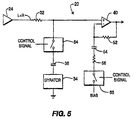
- Fig. 5 shows an alternate embodiment of the switching arrangement of Fig. 4 wherein the switch for the gyrator 34 and LC network 30 is removed from ground and is shown as a generic switch 64 responsive to a respective control signal, and the high pass filter circuit 38 is shown as being switched by a generic switch 66 responsive to its respective control signal.
- resistor 32 3.3 Kohms
- capacitor 36 0.22 uf
- resistor 46 68 Kohms
- resistor 44 1 Kohm
- resistor 50 2.2 Kohms
- resistors 52/56 15 Kohms
- capacitor 54 0.01uf.
- the transistors 42, 58, 60, and 62 can be non-critical signal types, e.g., 2N2222, and op-amp 40 is a non-critical general purpose MC3404 op-amp.
Description
Claims (8)
- A stereophonic audio system, comprising:characterized in that the means for processing further comprisesmeans (24) for providing a sum, L+R, and a difference, L-R, signals and respective signal paths from a pair of left, L, and right, R, signals;means (22) for providing a spatially expanded stereophonic audio effect in the L-R signal, andmeans (20) for processing the L+R signal for concentrating the apparent location of central sounds closer to the center between left and right sound emanating loudspeakers, the means (20) for processing comprising:means (30) for reducing signal levels at bass frequencies,means (38) for increasing signal levels at treble frequencies, and the means (30) for reducing signal levels at bass frequencies comprises a gyrator.
- The audio system of claim 1 wherein the reduction of signal levels at bass frequencies and the increase of signal levels at treble frequencies are switchable singly or in combination between "ON" and "OFF" modes.
- The audio system of claim 1 wherein the gyrator (34) is in shunt across the L + R signal path.
- The audio system of claim 1 wherein the means (38) for increasing signal levels at treble frequencies comprises a high pass filter in series with the L + R signal path.
- The audio system of claim 1 wherein the bass frequencies include frequencies within the band of 100 Hz to 580 Hz.
- The audio system of claim 1 wherein the treble signal frequencies include frequencies above 580 Hz.
- The audio system of claim 2 wherein the switching is responsive to control signals.
- The audio system of claim 7 wherein the control signals are provided by a microprocessor.
Applications Claiming Priority (3)
| Application Number | Priority Date | Filing Date | Title |
|---|---|---|---|
| US13400599P | 1999-05-13 | 1999-05-13 | |
| US134005P | 1999-05-13 | ||
| PCT/US2000/013049 WO2000070913A2 (en) | 1999-05-13 | 2000-05-12 | Centralizing of a spatially expanded stereophonic audio image |
Publications (2)
| Publication Number | Publication Date |
|---|---|
| EP1177707A2 EP1177707A2 (en) | 2002-02-06 |
| EP1177707B1 true EP1177707B1 (en) | 2004-09-15 |
Family
ID=22461328
Family Applications (1)
| Application Number | Title | Priority Date | Filing Date |
|---|---|---|---|
| EP00932346A Expired - Lifetime EP1177707B1 (en) | 1999-05-13 | 2000-05-12 | Centralizing of a spatially expanded stereophonic audio image |
Country Status (8)
| Country | Link |
|---|---|
| EP (1) | EP1177707B1 (en) |
| JP (1) | JP4868647B2 (en) |
| KR (1) | KR100699454B1 (en) |
| CN (1) | CN1227950C (en) |
| AU (1) | AU5008100A (en) |
| DE (1) | DE60013807T2 (en) |
| MX (1) | MXPA01011426A (en) |
| WO (1) | WO2000070913A2 (en) |
Families Citing this family (12)
| Publication number | Priority date | Publication date | Assignee | Title |
|---|---|---|---|---|
| TWI278851B (en) | 2003-02-25 | 2007-04-11 | Lg Electronics Inc | Recording medium having data structure for managing at least a data area of the recording medium and recording and reproducing methods and apparatuses |
| CN1308952C (en) * | 2003-03-03 | 2007-04-04 | 三星电子株式会社 | Method and apparatus for managing disc defect and disc therefor |
| US8223607B2 (en) | 2003-07-04 | 2012-07-17 | Lg Electronics Inc. | Method and apparatus for managing a overwrite recording on optical disc write once |
| KR101024916B1 (en) | 2004-03-19 | 2011-03-31 | 엘지전자 주식회사 | Method for writing data in high density optical write once disc and Apparatus for the same |
| KR101113866B1 (en) | 2004-03-19 | 2012-03-02 | 엘지전자 주식회사 | Data structure for a recording medium and method and apparatus of recording data on the recording medium |
| KR101049117B1 (en) | 2004-06-08 | 2011-07-14 | 엘지전자 주식회사 | Method and apparatus for recording management information on optical write once disc |
| KR101014727B1 (en) | 2004-06-23 | 2011-02-16 | 엘지전자 주식회사 | Method and Apparatus for managing a overwrite in Optical write once disc |
| KR101012378B1 (en) | 2004-08-16 | 2011-02-09 | 엘지전자 주식회사 | Method and Apparatus for recording / reproducing in Optical storage |
| JP5144265B2 (en) | 2004-09-14 | 2013-02-13 | エルジー エレクトロニクス インコーポレイティド | Recording medium and recording / reproducing method and apparatus for recording medium |
| GB2419265B (en) | 2004-10-18 | 2009-03-11 | Wolfson Ltd | Improved audio processing |
| KR101227485B1 (en) | 2005-11-25 | 2013-01-29 | 엘지전자 주식회사 | Recording mdium, Method and Apparatus for recording defect management information on the recording medium |
| KR20070058291A (en) | 2005-12-02 | 2007-06-08 | 엘지전자 주식회사 | Recording medium, method and apparatus for recording management information on the recording medium |
Family Cites Families (9)
| Publication number | Priority date | Publication date | Assignee | Title |
|---|---|---|---|---|
| CA1124339A (en) * | 1979-05-15 | 1982-05-25 | Israel Levi | Amplitude equalizer circuit |
| US4451927A (en) * | 1982-03-24 | 1984-05-29 | Harris Corporation | Separation correction method and apparatus for plural channel transmission system |
| US4748669A (en) * | 1986-03-27 | 1988-05-31 | Hughes Aircraft Company | Stereo enhancement system |
| US4759065A (en) * | 1986-09-22 | 1988-07-19 | Harman International Industries, Incorporated | Automotive sound system |
| US4866774A (en) * | 1988-11-02 | 1989-09-12 | Hughes Aircraft Company | Stero enhancement and directivity servo |
| JP2767389B2 (en) * | 1994-11-08 | 1998-06-18 | ローム株式会社 | Equalizer and audio device using the same |
| US5692050A (en) * | 1995-06-15 | 1997-11-25 | Binaura Corporation | Method and apparatus for spatially enhancing stereo and monophonic signals |
| JPH09252500A (en) * | 1996-03-15 | 1997-09-22 | Shuichi Sato | Stereo reproduction system in audio equipment |
| EP0808076B1 (en) * | 1996-05-17 | 2007-11-21 | Micronas GmbH | Surround sound system |
-
2000
- 2000-05-12 EP EP00932346A patent/EP1177707B1/en not_active Expired - Lifetime
- 2000-05-12 KR KR1020017013546A patent/KR100699454B1/en active IP Right Grant
- 2000-05-12 MX MXPA01011426A patent/MXPA01011426A/en active IP Right Grant
- 2000-05-12 JP JP2000619239A patent/JP4868647B2/en not_active Expired - Lifetime
- 2000-05-12 AU AU50081/00A patent/AU5008100A/en not_active Abandoned
- 2000-05-12 DE DE60013807T patent/DE60013807T2/en not_active Expired - Lifetime
- 2000-05-12 CN CNB008075379A patent/CN1227950C/en not_active Expired - Lifetime
- 2000-05-12 WO PCT/US2000/013049 patent/WO2000070913A2/en active IP Right Grant
Also Published As
| Publication number | Publication date |
|---|---|
| WO2000070913A9 (en) | 2002-04-18 |
| DE60013807T2 (en) | 2005-04-14 |
| CN1227950C (en) | 2005-11-16 |
| JP4868647B2 (en) | 2012-02-01 |
| WO2000070913A3 (en) | 2001-08-16 |
| KR20010110799A (en) | 2001-12-13 |
| DE60013807D1 (en) | 2004-10-21 |
| JP2003500916A (en) | 2003-01-07 |
| WO2000070913A2 (en) | 2000-11-23 |
| EP1177707A2 (en) | 2002-02-06 |
| AU5008100A (en) | 2000-12-05 |
| MXPA01011426A (en) | 2002-06-04 |
| KR100699454B1 (en) | 2007-03-27 |
| CN1364393A (en) | 2002-08-14 |
Similar Documents
| Publication | Publication Date | Title |
|---|---|---|
| US5930370A (en) | In-home theater surround sound speaker system | |
| CA2228051C (en) | Acoustic correction apparatus | |
| EP1177707B1 (en) | Centralizing of a spatially expanded stereophonic audio image | |
| US5265166A (en) | Multi-channel sound simulation system | |
| US6711265B1 (en) | Centralizing of a spatially expanded stereophonic audio image | |
| US6947564B1 (en) | Stereophonic spatial expansion circuit with tonal compensation and active matrixing | |
| JP3431959B2 (en) | Audio signal processing equipment | |
| US5533135A (en) | Crossover system | |
| US4257067A (en) | Sound enhancement system for television receivers | |
| JPS63194500A (en) | Stereoscopic reproducing device | |
| US3050583A (en) | Controllable stereophonic electroacoustic network | |
| EP1365625A2 (en) | Expanded stereophonic circuit with tonal compensation | |
| KR900010615Y1 (en) | Low frequency only amplifier circuit | |
| WO2000042819A1 (en) | A stereophonic spatial expansion circuit with tonal compensation and active matrixing | |
| US20020196950A1 (en) | Method and apparatus for treating an audio signal | |
| KR850003259Y1 (en) | Imitation stereo | |
| JPS5832362Y2 (en) | FM broadcast playback device | |
| KR930004104B1 (en) | Expansion circuit of stereo | |
| JPH04119708A (en) | Automatic noise suppression method for amplifier and automatic noise suppression device | |
| JPH0588020U (en) | Subwoofer output circuit | |
| JPH0136314B2 (en) | ||
| JPH10136496A (en) | Stereo sound source moving acoustic system | |
| JPH10304277A (en) | Television receiver | |
| JPS6412160B2 (en) | ||
| JPS62202607A (en) | Power amplification system |
Legal Events
| Date | Code | Title | Description |
|---|---|---|---|
| PUAI | Public reference made under article 153(3) epc to a published international application that has entered the european phase |
Free format text: ORIGINAL CODE: 0009012 |
|
| 17P | Request for examination filed |
Effective date: 20011102 |
|
| AK | Designated contracting states |
Kind code of ref document: A2 Designated state(s): AT BE CH CY DE DK ES FI FR GB GR IE IT LI LU MC NL PT SE |
|
| AX | Request for extension of the european patent |
Free format text: AL;LT;LV;MK;RO;SI |
|
| 17Q | First examination report despatched |
Effective date: 20021230 |
|
| GRAP | Despatch of communication of intention to grant a patent |
Free format text: ORIGINAL CODE: EPIDOSNIGR1 |
|
| GRAS | Grant fee paid |
Free format text: ORIGINAL CODE: EPIDOSNIGR3 |
|
| GRAA | (expected) grant |
Free format text: ORIGINAL CODE: 0009210 |
|
| AK | Designated contracting states |
Kind code of ref document: B1 Designated state(s): DE FR GB IT |
|
| REG | Reference to a national code |
Ref country code: GB Ref legal event code: FG4D |
|
| REG | Reference to a national code |
Ref country code: IE Ref legal event code: FG4D |
|
| REF | Corresponds to: |
Ref document number: 60013807 Country of ref document: DE Date of ref document: 20041021 Kind code of ref document: P |
|
| REG | Reference to a national code |
Ref country code: GB Ref legal event code: 746 Effective date: 20041026 |
|
| LTIE | Lt: invalidation of european patent or patent extension |
Effective date: 20040915 |
|
| PLBE | No opposition filed within time limit |
Free format text: ORIGINAL CODE: 0009261 |
|
| STAA | Information on the status of an ep patent application or granted ep patent |
Free format text: STATUS: NO OPPOSITION FILED WITHIN TIME LIMIT |
|
| ET | Fr: translation filed | ||
| 26N | No opposition filed |
Effective date: 20050616 |
|
| REG | Reference to a national code |
Ref country code: FR Ref legal event code: D6 |
|
| REG | Reference to a national code |
Ref country code: FR Ref legal event code: PLFP Year of fee payment: 17 |
|
| REG | Reference to a national code |
Ref country code: FR Ref legal event code: PLFP Year of fee payment: 18 |
|
| REG | Reference to a national code |
Ref country code: DE Ref legal event code: R082 Ref document number: 60013807 Country of ref document: DE Representative=s name: DEHNS PATENT AND TRADEMARK ATTORNEYS, DE Ref country code: DE Ref legal event code: R082 Ref document number: 60013807 Country of ref document: DE Representative=s name: DEHNS PATENT AND TRADE MARK ATTORNEYS, DE Ref country code: DE Ref legal event code: R082 Ref document number: 60013807 Country of ref document: DE Representative=s name: HOFSTETTER, SCHURACK & PARTNER PATENT- UND REC, DE |
|
| REG | Reference to a national code |
Ref country code: FR Ref legal event code: PLFP Year of fee payment: 19 |
|
| REG | Reference to a national code |
Ref country code: FR Ref legal event code: TP Owner name: THOMSON LICENSING DTV, FR Effective date: 20180830 |
|
| REG | Reference to a national code |
Ref country code: GB Ref legal event code: 732E Free format text: REGISTERED BETWEEN 20180927 AND 20181005 |
|
| REG | Reference to a national code |
Ref country code: DE Ref legal event code: R082 Ref document number: 60013807 Country of ref document: DE Representative=s name: DEHNS PATENT AND TRADEMARK ATTORNEYS, DE Ref country code: DE Ref legal event code: R081 Ref document number: 60013807 Country of ref document: DE Owner name: INTERDIGITAL MADISON PATENT HOLDINGS, FR Free format text: FORMER OWNER: THOMSON LICENSING S.A., BOULOGNE, CEDEX, FR Ref country code: DE Ref legal event code: R082 Ref document number: 60013807 Country of ref document: DE Representative=s name: DEHNS PATENT AND TRADE MARK ATTORNEYS, DE |
|
| PGFP | Annual fee paid to national office [announced via postgrant information from national office to epo] |
Ref country code: DE Payment date: 20190418 Year of fee payment: 20 Ref country code: IT Payment date: 20190418 Year of fee payment: 20 |
|
| PGFP | Annual fee paid to national office [announced via postgrant information from national office to epo] |
Ref country code: FR Payment date: 20190419 Year of fee payment: 20 |
|
| PGFP | Annual fee paid to national office [announced via postgrant information from national office to epo] |
Ref country code: GB Payment date: 20190423 Year of fee payment: 20 |
|
| REG | Reference to a national code |
Ref country code: DE Ref legal event code: R071 Ref document number: 60013807 Country of ref document: DE |
|
| REG | Reference to a national code |
Ref country code: GB Ref legal event code: PE20 Expiry date: 20200511 |
|
| PG25 | Lapsed in a contracting state [announced via postgrant information from national office to epo] |
Ref country code: GB Free format text: LAPSE BECAUSE OF EXPIRATION OF PROTECTION Effective date: 20200511 |