EP0776432B1 - Vorrichtung zur umwandlung einer dreh- in eine axialbewegung - Google Patents
Vorrichtung zur umwandlung einer dreh- in eine axialbewegung Download PDFInfo
- Publication number
- EP0776432B1 EP0776432B1 EP96922736A EP96922736A EP0776432B1 EP 0776432 B1 EP0776432 B1 EP 0776432B1 EP 96922736 A EP96922736 A EP 96922736A EP 96922736 A EP96922736 A EP 96922736A EP 0776432 B1 EP0776432 B1 EP 0776432B1
- Authority
- EP
- European Patent Office
- Prior art keywords
- drive
- grooves
- planetary rollers
- drive shaft
- bearing
- Prior art date
- Legal status (The legal status is an assumption and is not a legal conclusion. Google has not performed a legal analysis and makes no representation as to the accuracy of the status listed.)
- Expired - Lifetime
Links
Images


Classifications
-
- F—MECHANICAL ENGINEERING; LIGHTING; HEATING; WEAPONS; BLASTING
- F16—ENGINEERING ELEMENTS AND UNITS; GENERAL MEASURES FOR PRODUCING AND MAINTAINING EFFECTIVE FUNCTIONING OF MACHINES OR INSTALLATIONS; THERMAL INSULATION IN GENERAL
- F16H—GEARING
- F16H25/00—Gearings comprising primarily only cams, cam-followers and screw-and-nut mechanisms
- F16H25/18—Gearings comprising primarily only cams, cam-followers and screw-and-nut mechanisms for conveying or interconverting oscillating or reciprocating motions
- F16H25/20—Screw mechanisms
- F16H25/22—Screw mechanisms with balls, rollers, or similar members between the co-operating parts; Elements essential to the use of such members
- F16H25/2247—Screw mechanisms with balls, rollers, or similar members between the co-operating parts; Elements essential to the use of such members with rollers
- F16H25/2252—Planetary rollers between nut and screw
Definitions
- the invention relates to a device for converting a Rotational in an axial movement according to the preamble of the claim 1.
- Such a device is known from DE-U-87 02 656.2.
- the invention deals with the Problem, a generic device in a constructive functionally as compact and simple as possible improve.
- the drive shaft can be of one drive unit located within the thrust body, such as an electric motor.
- This drive unit can be arranged stationary.
- the cage in which the planetary rollers are stored can serve to lead the planetary roles and that of the planetary roles absorbing outgoing axial forces.
- the cage is axially fixed to the drive housing.
- the axial forces of the planetary rollers can also be direct be taken up by the drive shaft.
- the drive shaft axially fixed to the drive housing to store.
- the planetary rollers can also be attached to the drive shaft to their drive grooves with bearing grooves that axially force-supporting in corresponding bearing grooves of the drive shaft intervention.
- the counter grooves engaging in the bearing grooves of the planetary rollers or counter profiles do not have to be part of the drive shaft be. You just have to rotate and face each other be axially fixed to the drive housing.
- the drive housing for the drive unit of the drive shaft is particularly within the serving as a thrust body Arranged hollow body.
- the hollow body preferably has the shape of a tube provided with an internal groove.
- the drive grooves the planetary rollers at the same time as their bearing grooves axial support on a rotating radially inside the Serve orbit of the planet rollers lying bearing body.
- the bearing body can also be fixed to the drive shaft in this case be connected, but then the drive grooves the planetary rollers and the bearing grooves of the Bearing body should each be designed without a slope. Furthermore, the values of the average diameter of the grooves of the bearing body and Rolling circle of the teeth between the drive pinion Drive shaft and the planetary rollers match. This basically applies to designs where drive grooves the planetary rollers in counter-grooves of a drive shaft intervene, which is directly interlocked with the planetary rollers.
- the internal grooving of the hollow body can in particular be a be multi-start thread.
- the rotatably interlocking parts of the drive device is a multi-start thread especially with Regarding the grooving of the hollow body necessary.
- the device according to the invention has the advantage that the thrust body in the form of a tube over a distance can be extended on which no guide body previously must be present.
- the thrust body has a high kink resistance.
- the drive elements inside the tube simply by closing the tube at each end and can be safely encapsulated.
- the thrust body can the housing of the Drive unit can be easily sealed.
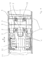
- a drive housing 11 housed electric motor driven drive shaft 1 is provided with a pinion 2.
- the pinion 2 drives a total of four planet rollers 3 that on the drive housing 11 facing the electric motor Each end with a toothing area 4 are.
- the drive of the planetary rollers 3 using the pinion 2 takes place in each case via these toothed areas 4.
- the planetary rollers 3 are stored in a cage 5.
- the cage 5 is in one the drive housing 11 mounted fixed bearing ring 12 and axially fixed.
- the planetary rollers 3 By storing in the cage 5 are the planetary rollers 3 axially and in the circumferential direction unique and fixed immutable.
- the planetary rollers 3 engage from the inside radially in a hollow A thrust body 6, which in the present case as a kind Tube is formed.
- Both the planetary rollers 3 and the thrust body 6 are each provided with circumferential grooves 8 and 7, respectively, in In the example shown, both grooves are thread grooves. However, it is sufficient that only one of these is a thread groove in both grooves.
- the slope of these grooves 7 and 8, or only one of these two grooves if only one thread groove is provided is the gear ratio between the number of revolutions the drive shaft 1 and the axial travel of the thrust body 6 determined. The exact ratio results from the Equation given at the beginning for the axial travel of the thrust body 6.
- the thrust body 6 can only perform an axial movement execute what he stored and managed accordingly is. With a thread inside the thrust body 6 can this be multi-course.
- the planet rollers 3 additional bearing grooves 9 which are formed radially deeper are as the grooves 7 and 8. Grab these bearing grooves 9 the planetary rollers 3 in corresponding grooves 10 one Bearing body 13 firmly connected to the drive shaft 1 a, whereby an axial fixation of the planet rollers 3 at an axially unfixed cage 5 is reached.
- the thrust body moves 6 depending on the design of the slope of the grooves 7 and 8 and according to the direction of rotation of the drive shaft 1 in one of the directions indicated by the arrow R.
- the bearing body 13 axially fixed freely rotatably mounted on the drive shaft 1 namely via two axial roller bearings 14, each of which one on each of the two faces of the bearing body 13 is provided.
- the pitch circle diameter of the drive pinion 2 with respect to its engagement in the toothing area 4 of the planetary rollers 3 independently of the average diameter of the bearing grooves 10 des Bearing body 13 can be selected.
- the drive grooves of the planetary rollers 3, which are in this version can also serve as bearing grooves at the same time be pitchless grooves or a thread groove.
- the planetary rollers 3 equipped with thread grooves so must the bearing body 13 have corresponding thread grooves.
- the planetary rollers 3, on the other hand, have pitchless grooves provided, so the bearing body 13 must be shaped accordingly Have grooves.
- the drive pinion 2 can be gimbally driven via a clutch be so that between the drive shaft and the Axis of the thrust body 6 a pivot angle can be realized can.
Description
- Sax =
- Axialweg des Schubkörpers
- Ua =
- Anzahl der Umdrehungen der Antriebswelle
- Ps =
- Steigung der Rillen des Schubkörpers
- Pr =
- Steigung der Rillen der Planetenrollen
- dgs =
- Durchmesser der Rillen des Schubkörpers
- dgr =
- Durchmesser der Rillen der Planetenrollen
- dwa =
- Wälzkreisdurchmesser der Verzahnung des Antriebswellen-Ritzels
- dwr =
- Wälzkreisdurchmesser der Verzahnung der Planetenrollen.
- Fig. 1
- einen Längsschnitt durch eine Antriebsvorrichtung mit einem hohlen Schubkörper und einem gelagerten Planetenrollen-Käfig,
- Fig. 2
- einen Schnitt durch die Antriebsvorrichtung nach Linie II-II in Fig. 1,
- Fig. 3
- einen Schnitt durch eine Antriebsvorrichtung wie in Fig. 1, bei der die Planetenrollen über in diesen zusätzlich vorgesehene steigungslose Lagerrillen axial fixiert sind,
- Fig. 4
- einen Längsschnitt durch eine Antriebsvorrichtung wie in Fig. 1, bei der die Planetenrollen zu ihrer axialen Fixierung mit ihren Antriebsrillen in Gegenrillen eines gegenüber der Antriebswelle rotierend gelagerten Lagerkörpers eingreifen.
Claims (9)
- Vorrichtung zur Umwandlung einer Dreh- in eine Axialbewegung mit von einer Antriebswelle aus einem ortsfesten Antriebsgehäuse heraus angetriebenen umfangsmäßig auf gleichem Abstand gehaltenen Planetenrollen und einem durch die Planetenrollen axial verschiebbaren Schubkörper, bei derdadurch gekennzeichnet, daß die Antriebsrillen (8) der Planetenrollen (3) die Antriebswelle (1) nicht berühren.a) die Antriebswelle (1) mit einem Antriebszahnrad (2) versehen ist,b) das Antriebszahnrad (2) in Planetenrollen (3) kämmt, die für den Eingriff des Antriebszahnrades (2) einen Bereich mit Verzahnung aufweisen,c) die Planetenrollen einen mit Antriebsrillen (8) versehenen Bereich besitzen und axial gegenüber der Antriebswelle (1) fixiert gelagert sind,d) der Schubkörper (6) mit Antriebsrillen (7) versehen ist,e) die Planetenrollen (3) den Schubkörper (6) antreiben, indem ihre Antriebsrillen (8) in die Antriebsrillen (7) des Schubkörpers eingreifen,f) die Rillen (7 bzw. 8) mindestens des Schubkörpers (6) oder der Planetenrollen (3) Gewinderillen sind,g) die Antriebswelle (1) in einem Zentrum der Kreisumlaufbahn der Planetenrollen (3) gelagert ist,h) der Schubkörper (6) ein die Planetenrollen (3) umfassender Hohlkörper ist,i) die Planetenrollen (3) in einem rotierbaren Käfig (5) gelagert sind,
- Vorrichtung nach Anspruch 1,
dadurch gekennzeichnet, daß der Käfig (5) an dem Antriebsgehäuse (11) der Antriebswelle (1) axial fixiert wälzgelagert ist. - Vorrichtung nach Anspruch 1,
dadurch gekennzeichnet, daß in den Planetenrollen (3) Lagerrillen (9) vorgesehen sind, mit denen die Planetenrollen (3) in entsprechend axial unbeweglichen Gegen-Lagerrillen (10) axial fixiert sind. - Vorrichtung nach Anspruch 3,
dadurch gekennzeichnet, daß die Gegenrillen (10) Bestandteil der Antriebswelle (1) sind. - Vorrichtung nach Anspruch 1,
dadurch gekennzeichnet, daß die Antriebsrillen (8) der Planetenrollen (3) in axial unverschiebbare Gegen-Lagerrillen (10) eines in der Achse der Antriebswelle (2) rotierenden Lagerkörpers (13) eingreifen. - Vorrichtung nach Anspruch 4,
dadurch gekennzeichnet, daß der Lagerkörper (13) fest mit der Antriebswelle (1) verbunden ist und daß die Antriebs- und Lagerrillen der Planetenrollen (3) bzw. des Lagerkörpers (13) jeweils steigungslos sind. - Vorrichtung nach einem der Ansprüche 4 bis 6,
dadurch gekennzeichnet, daß die Werte des mittleren Durchmessers der Lagerrillen (10) des Lagerkörpers (13) und des Wälzkreisdurchmessers der Verzahnung zwischen dem Antriebsritzel (2) und den Planetenrollen (3) übereinstimmen. - Vorrichtung nach Anspruch 5,
dadurch gekennzeichnet, daß der Lagerkörper (13) axial fixiert, drehbar an der Antriebswelle (1) gelagert ist. - Vorrichtung nach einem der vorhergehenden Ansprüche,
dadurch gekennzeichnet, daß das Antriebsgehäuse (11) innerhalb eines als Schubkörper (6) dienenden Hohlkörpers liegt.
Applications Claiming Priority (3)
| Application Number | Priority Date | Filing Date | Title |
|---|---|---|---|
| DE19524772 | 1995-07-07 | ||
| DE19524772 | 1995-07-07 | ||
| PCT/DE1996/001187 WO1997003308A1 (de) | 1995-07-07 | 1996-06-27 | Vorrichtung zur umwandlung einer dreh- in eine axialbewegung |
Publications (2)
| Publication Number | Publication Date |
|---|---|
| EP0776432A1 EP0776432A1 (de) | 1997-06-04 |
| EP0776432B1 true EP0776432B1 (de) | 1998-11-25 |
Family
ID=7766254
Family Applications (1)
| Application Number | Title | Priority Date | Filing Date |
|---|---|---|---|
| EP96922736A Expired - Lifetime EP0776432B1 (de) | 1995-07-07 | 1996-06-27 | Vorrichtung zur umwandlung einer dreh- in eine axialbewegung |
Country Status (5)
| Country | Link |
|---|---|
| EP (1) | EP0776432B1 (de) |
| JP (1) | JP3863182B2 (de) |
| AT (1) | ATE173801T1 (de) |
| DE (2) | DE59600862D1 (de) |
| WO (1) | WO1997003308A1 (de) |
Cited By (1)
| Publication number | Priority date | Publication date | Assignee | Title |
|---|---|---|---|---|
| DE102009011661A1 (de) | 2009-03-04 | 2010-09-09 | Wittenstein Ag | Wachstumsprothese |
Families Citing this family (8)
| Publication number | Priority date | Publication date | Assignee | Title |
|---|---|---|---|---|
| DE19700225A1 (de) | 1997-01-07 | 1998-07-09 | Augustin Prof Dr Betz | Distraktionsvorrichtung zum Auseinanderbewegen zweier Teile eines Knochens |
| DE19713351A1 (de) | 1997-03-29 | 1998-10-01 | Wittenstein Gmbh & Co Kg | Vorrichtung zur Umwandlung einer Dreh- in eine Axialbewegung |
| DE10022115A1 (de) | 2000-05-06 | 2001-11-08 | Wittenstein Gmbh & Co Kg | Vorrichtung zur Umwandlung einer Dreh-in eine Axialbewegung |
| DE10063772A1 (de) * | 2000-12-21 | 2002-06-27 | Wittenstein Motion Contr Gmbh | Vorrichtung zur Umwandlung einer Dreh- in eine Axialbewegung |
| DE102004054037B3 (de) * | 2004-11-05 | 2006-10-05 | Stabilus Gmbh | Verstellvorrichtung |
| JP4186969B2 (ja) | 2005-08-23 | 2008-11-26 | トヨタ自動車株式会社 | 遊星式回転−直線運動変換装置 |
| CN107654601B (zh) * | 2006-06-22 | 2020-04-21 | 丰田自动车株式会社 | 旋转直线运动转换机构的制造方法以及用于实施该方法的夹具 |
| JP2010263670A (ja) * | 2009-04-30 | 2010-11-18 | Mitsuba Corp | リニアアクチュエータ |
Family Cites Families (3)
| Publication number | Priority date | Publication date | Assignee | Title |
|---|---|---|---|---|
| SE8107545L (sv) * | 1981-12-16 | 1983-06-17 | Bo Granbom | Anordning for att omvandla en roterande rorelse till en linjer rorelse |
| DE8702656U1 (de) * | 1986-08-28 | 1987-10-08 | Pradler, Josef, 7312 Kirchheim, De | |
| US5557154A (en) * | 1991-10-11 | 1996-09-17 | Exlar Corporation | Linear actuator with feedback position sensor device |
-
1996
- 1996-06-27 JP JP50540497A patent/JP3863182B2/ja not_active Expired - Fee Related
- 1996-06-27 AT AT96922736T patent/ATE173801T1/de not_active IP Right Cessation
- 1996-06-27 DE DE59600862T patent/DE59600862D1/de not_active Expired - Lifetime
- 1996-06-27 DE DE19625761A patent/DE19625761A1/de not_active Withdrawn
- 1996-06-27 EP EP96922736A patent/EP0776432B1/de not_active Expired - Lifetime
- 1996-06-27 WO PCT/DE1996/001187 patent/WO1997003308A1/de active IP Right Grant
Cited By (2)
| Publication number | Priority date | Publication date | Assignee | Title |
|---|---|---|---|---|
| DE102009011661A1 (de) | 2009-03-04 | 2010-09-09 | Wittenstein Ag | Wachstumsprothese |
| EP2292187A2 (de) | 2009-03-04 | 2011-03-09 | Wittenstein AG | Wachstumsprothese |
Also Published As
| Publication number | Publication date |
|---|---|
| EP0776432A1 (de) | 1997-06-04 |
| JPH10505659A (ja) | 1998-06-02 |
| WO1997003308A1 (de) | 1997-01-30 |
| JP3863182B2 (ja) | 2006-12-27 |
| DE59600862D1 (de) | 1999-01-07 |
| DE19625761A1 (de) | 1997-01-09 |
| ATE173801T1 (de) | 1998-12-15 |
Similar Documents
| Publication | Publication Date | Title |
|---|---|---|
| DE112007002103B4 (de) | Rollelement-Schraubspindelvorrichtung | |
| DE3110079A1 (de) | Drehantrieb fuer rollvorhaenge, rollaeden oder dergleichen | |
| EP1608497A2 (de) | Getriebe zum antrieb eines mehrwellenextruders, wobei das drehmonent über inneres antriebsrad und äusseres hohlrad gleichermassen eingeleitet wird | |
| DE3732811A1 (de) | Drehkraft-uebertragungsvorrichtung fuer ein fahrzeug mit vierradantrieb | |
| EP2933415B1 (de) | Türantrieb | |
| EP0776432B1 (de) | Vorrichtung zur umwandlung einer dreh- in eine axialbewegung | |
| DE19723358B4 (de) | Motorbetriebenes Servolenksystem | |
| EP3936424B1 (de) | Elektrischer hilfsantrieb für ein fahrrad | |
| WO2017092740A1 (de) | Umlaufrädergetriebe für eine kraftfahrzeugantriebseinheit | |
| EP1099063B1 (de) | Motor-getriebe-einheit | |
| EP0642834B1 (de) | Verriegelungsvorrichtung für eine Lageranordnung, insbesondere für die Separationskammer einer Zentrifuge | |
| DE3636855A1 (de) | Untersetzungsgetriebe, insbesondere zum einbau in einen gurtkasten eines elektromotorisch angetriebenen gurtwicklers fuer einen rolladen od. dgl. | |
| WO2014044277A1 (de) | Getriebeanordnung | |
| DE102006042511B4 (de) | Kompakte Verriegelungsvorrichtung | |
| WO2019242980A1 (de) | Radantriebsmodul mit einem in dem radantriebsmodul aufgenommenen rad | |
| EP3622200A1 (de) | Getriebe | |
| WO1997025554A2 (de) | Vorrichtung zur umwandlung einer dreh- in eine axialbewegung | |
| EP0432349A2 (de) | Getriebe | |
| DE2947088C2 (de) | Getriebe | |
| WO2002063747A2 (de) | Verzahnungsteil eines getriebemotors, baureihe von getriebemotoren und verbindung | |
| WO2006066813A1 (de) | Vorrichtung, insbesondere ein planetengetriebe, mit einem ringartigen grundkörper | |
| DE102020101918A1 (de) | Getriebe für einen Elektroantrieb eines Kraftfahrzeuges | |
| WO2019242945A1 (de) | Radantriebsmodul zum antrieb und zur lenkung eines rades | |
| EP2008913B1 (de) | Lenkgetriebe für ein Fahrzeug | |
| EP1094247B1 (de) | Schneckengetriebeantrieb |
Legal Events
| Date | Code | Title | Description |
|---|---|---|---|
| PUAI | Public reference made under article 153(3) epc to a published international application that has entered the european phase |
Free format text: ORIGINAL CODE: 0009012 |
|
| 17P | Request for examination filed |
Effective date: 19970222 |
|
| AK | Designated contracting states |
Kind code of ref document: A1 Designated state(s): AT CH DE FR GB IT LI SE |
|
| GRAG | Despatch of communication of intention to grant |
Free format text: ORIGINAL CODE: EPIDOS AGRA |
|
| GRAG | Despatch of communication of intention to grant |
Free format text: ORIGINAL CODE: EPIDOS AGRA |
|
| GRAH | Despatch of communication of intention to grant a patent |
Free format text: ORIGINAL CODE: EPIDOS IGRA |
|
| RAP1 | Party data changed (applicant data changed or rights of an application transferred) |
Owner name: WITTENSTEIN GMBH & CO. KG |
|
| GRAH | Despatch of communication of intention to grant a patent |
Free format text: ORIGINAL CODE: EPIDOS IGRA |
|
| 17Q | First examination report despatched |
Effective date: 19980814 |
|
| GRAA | (expected) grant |
Free format text: ORIGINAL CODE: 0009210 |
|
| AK | Designated contracting states |
Kind code of ref document: B1 Designated state(s): AT CH DE FR GB IT LI SE |
|
| REF | Corresponds to: |
Ref document number: 173801 Country of ref document: AT Date of ref document: 19981215 Kind code of ref document: T |
|
| REG | Reference to a national code |
Ref country code: CH Ref legal event code: EP |
|
| GBT | Gb: translation of ep patent filed (gb section 77(6)(a)/1977) |
Effective date: 19981209 |
|
| REF | Corresponds to: |
Ref document number: 59600862 Country of ref document: DE Date of ref document: 19990107 |
|
| ITF | It: translation for a ep patent filed |
Owner name: DE DOMINICIS & MAYER S.R.L. |
|
| ET | Fr: translation filed | ||
| PLBE | No opposition filed within time limit |
Free format text: ORIGINAL CODE: 0009261 |
|
| STAA | Information on the status of an ep patent application or granted ep patent |
Free format text: STATUS: NO OPPOSITION FILED WITHIN TIME LIMIT |
|
| 26N | No opposition filed | ||
| REG | Reference to a national code |
Ref country code: GB Ref legal event code: IF02 |
|
| PGFP | Annual fee paid to national office [announced via postgrant information from national office to epo] |
Ref country code: AT Payment date: 20020618 Year of fee payment: 7 |
|
| PGFP | Annual fee paid to national office [announced via postgrant information from national office to epo] |
Ref country code: SE Payment date: 20020619 Year of fee payment: 7 Ref country code: FR Payment date: 20020619 Year of fee payment: 7 |
|
| PGFP | Annual fee paid to national office [announced via postgrant information from national office to epo] |
Ref country code: CH Payment date: 20020625 Year of fee payment: 7 |
|
| PG25 | Lapsed in a contracting state [announced via postgrant information from national office to epo] |
Ref country code: AT Free format text: LAPSE BECAUSE OF NON-PAYMENT OF DUE FEES Effective date: 20030627 |
|
| PG25 | Lapsed in a contracting state [announced via postgrant information from national office to epo] |
Ref country code: SE Free format text: LAPSE BECAUSE OF NON-PAYMENT OF DUE FEES Effective date: 20030628 |
|
| PG25 | Lapsed in a contracting state [announced via postgrant information from national office to epo] |
Ref country code: LI Free format text: LAPSE BECAUSE OF NON-PAYMENT OF DUE FEES Effective date: 20030630 Ref country code: CH Free format text: LAPSE BECAUSE OF NON-PAYMENT OF DUE FEES Effective date: 20030630 |
|
| EUG | Se: european patent has lapsed | ||
| REG | Reference to a national code |
Ref country code: CH Ref legal event code: PL |
|
| PG25 | Lapsed in a contracting state [announced via postgrant information from national office to epo] |
Ref country code: FR Free format text: LAPSE BECAUSE OF NON-PAYMENT OF DUE FEES Effective date: 20040227 |
|
| REG | Reference to a national code |
Ref country code: FR Ref legal event code: ST |
|
| PGFP | Annual fee paid to national office [announced via postgrant information from national office to epo] |
Ref country code: GB Payment date: 20120622 Year of fee payment: 17 |
|
| PGFP | Annual fee paid to national office [announced via postgrant information from national office to epo] |
Ref country code: IT Payment date: 20120628 Year of fee payment: 17 |
|
| GBPC | Gb: european patent ceased through non-payment of renewal fee |
Effective date: 20130627 |
|
| PG25 | Lapsed in a contracting state [announced via postgrant information from national office to epo] |
Ref country code: GB Free format text: LAPSE BECAUSE OF NON-PAYMENT OF DUE FEES Effective date: 20130627 |
|
| PG25 | Lapsed in a contracting state [announced via postgrant information from national office to epo] |
Ref country code: IT Free format text: LAPSE BECAUSE OF NON-PAYMENT OF DUE FEES Effective date: 20130627 |
|
| REG | Reference to a national code |
Ref country code: DE Ref legal event code: R082 Ref document number: 59600862 Country of ref document: DE Representative=s name: PATENTANWAELTE UND RECHTSANWALT WEISS, ARAT & , DE Ref country code: DE Ref legal event code: R082 Ref document number: 59600862 Country of ref document: DE Representative=s name: PATENTANWAELTE UND RECHTSANWALT DR. WEISS, ARA, DE |
|
| PGFP | Annual fee paid to national office [announced via postgrant information from national office to epo] |
Ref country code: DE Payment date: 20150828 Year of fee payment: 20 |
|
| REG | Reference to a national code |
Ref country code: DE Ref legal event code: R071 Ref document number: 59600862 Country of ref document: DE |