EP0776229B1 - Douche nozzle - Google Patents
Douche nozzle Download PDFInfo
- Publication number
- EP0776229B1 EP0776229B1 EP95927526A EP95927526A EP0776229B1 EP 0776229 B1 EP0776229 B1 EP 0776229B1 EP 95927526 A EP95927526 A EP 95927526A EP 95927526 A EP95927526 A EP 95927526A EP 0776229 B1 EP0776229 B1 EP 0776229B1
- Authority
- EP
- European Patent Office
- Prior art keywords
- grooves
- apertures
- nozzle
- fluid
- douche
- Prior art date
- Legal status (The legal status is an assumption and is not a legal conclusion. Google has not performed a legal analysis and makes no representation as to the accuracy of the status listed.)
- Expired - Lifetime
Links
- 229940059082 douche Drugs 0.000 title claims abstract description 36
- 239000012530 fluid Substances 0.000 claims abstract description 60
- 210000001215 vagina Anatomy 0.000 claims 1
- 239000000463 material Substances 0.000 description 5
- 238000010276 construction Methods 0.000 description 4
- 230000000694 effects Effects 0.000 description 3
- 210000003679 cervix uteri Anatomy 0.000 description 2
- 208000014617 hemorrhoid Diseases 0.000 description 2
- 239000000314 lubricant Substances 0.000 description 2
- 238000000034 method Methods 0.000 description 2
- 239000004033 plastic Substances 0.000 description 2
- 229920003023 plastic Polymers 0.000 description 2
- -1 polyethylene Polymers 0.000 description 2
- 239000004698 Polyethylene Substances 0.000 description 1
- 239000004743 Polypropylene Substances 0.000 description 1
- 238000000071 blow moulding Methods 0.000 description 1
- 239000007924 injection Substances 0.000 description 1
- 238000001746 injection moulding Methods 0.000 description 1
- 230000002262 irrigation Effects 0.000 description 1
- 238000003973 irrigation Methods 0.000 description 1
- 239000007788 liquid Substances 0.000 description 1
- 238000004519 manufacturing process Methods 0.000 description 1
- 238000000465 moulding Methods 0.000 description 1
- 239000002674 ointment Substances 0.000 description 1
- 229920000573 polyethylene Polymers 0.000 description 1
- 229920000642 polymer Polymers 0.000 description 1
- 229920001155 polypropylene Polymers 0.000 description 1
Images


Classifications
-
- A—HUMAN NECESSITIES
- A61—MEDICAL OR VETERINARY SCIENCE; HYGIENE
- A61M—DEVICES FOR INTRODUCING MEDIA INTO, OR ONTO, THE BODY; DEVICES FOR TRANSDUCING BODY MEDIA OR FOR TAKING MEDIA FROM THE BODY; DEVICES FOR PRODUCING OR ENDING SLEEP OR STUPOR
- A61M3/00—Medical syringes, e.g. enemata; Irrigators
- A61M3/02—Enemata; Irrigators
- A61M3/0279—Cannula; Nozzles; Tips; their connection means
-
- Y—GENERAL TAGGING OF NEW TECHNOLOGICAL DEVELOPMENTS; GENERAL TAGGING OF CROSS-SECTIONAL TECHNOLOGIES SPANNING OVER SEVERAL SECTIONS OF THE IPC; TECHNICAL SUBJECTS COVERED BY FORMER USPC CROSS-REFERENCE ART COLLECTIONS [XRACs] AND DIGESTS
- Y10—TECHNICAL SUBJECTS COVERED BY FORMER USPC
- Y10S—TECHNICAL SUBJECTS COVERED BY FORMER USPC CROSS-REFERENCE ART COLLECTIONS [XRACs] AND DIGESTS
- Y10S604/00—Surgery
- Y10S604/902—Suction wands
Definitions
- This invention relates to a novel douche nozzle for use in the application of vaginal douche fluids.
- Douche products are known and generally comprise a nozzle in the form of an elongate tubular body made of smooth surfaced material, e.g smooth plastics material, with an opening in their proximal end for entry of a douche fluid, a generally longitudinal channel for the fluid, and one or more lateral apertures in the walls of the body for outward lateral flow of the fluid during use.
- nozzles are attachable at their proximal end to a squeeze bottle or other container for the fluid, e.g. by a screw thread or other type of convenient connector.
- DE-A-3 318 257 discloses a haemorrhoids treatment device comprising a tubular body with a fluted outer surface, an axial channel and side channels, for the dispensing of a viscous haemorrhoids ointment.
- Known douche nozzles suffer from the problem that the flow rate of fluid out through the apertures has not been optimised. A further problem is that transfer of fluid from the channel out through the apertures has not been optimised, which may cause development of pressure and poor performance in cleansing. Further it is desirable that the cervix is not irrigated by the douche fluid, and known douche nozzles do not achieve this requirement.
- a douche nozzle as defined by claim 1 is provided.
- the characterising feature of the invention contributes to the effect of ensuring that the pressure of the fluid drops as the fluid flows from the channel out through the apertures and along the grooves.
- the grooves are of such a size, shape, and orientation relative to the surface of the nozzle that in use there is less resistance to fluid flow along the grooves than there is resistance to fluid flow out through the apertures. This too contributes to the effect of ensuring that there is less fluid pressure as the fluid comes into contact with human tissue.
- the total area of the apertures in the surface of the body is greater than the cross sectional area of the longitudinal channel, at least between the opening at the proximal end and the apertures. This contributes to the avoidance of a squirting or jetting effect of the fluid out through the apertures.
- the ratio total area of the apertures: cross sectional area of the longitudinal channel may be in the range 1.0001 : 1 to 3 : 1, suitably between about 1.01 : 1 to 2 : 1.
- the constructional features of the nozzle of the invention are such that the resistance to fluid flow pressure is greatest inside the channel, before the fluid contacts the tissue, thus preventing any build up of pressure as the fluid flows out of the nozzle through the apertures and along the grooves and as it comes into contact with vaginal tissue during use.
- an object achieved by the nozzle of the invention is a reduction of fluid flow pressure at the interface between the nozzle and the vaginal tissue. Resistance to fluid flow is greatest inside the nozzle, is less across the apertures and is reduced again in the grooves, thus ensuring that little pressure is developed as the fluid contacts the vaginal tissue.
- the whole or part of the flow of fluid is diverted by the fluid diverter means from a lateral into a distal to proximal direction.
- the apertures may be within 0.15 and 0.5, preferably within 0.2 and 0.4, of the distance from the distal end to the proximal end.
- part of the fluid flow may be diverted into other directions, e.g. tangentially to the surface of the nozzle, or in a plane including the longitudinal axis of the nozzle.
- the flow of fluid is diverted by diverter means comprising the location of each aperture in the surface of the body, and/or by the location of each aperture adjacent to one or more diverter surfaces which are so profiled and/or positioned that at least part of the flow encounters the diverter surface and is thereby diverted. If the walls of the body are thick enough the diverter means may also comprise a profiling of the walls of the apertures.
- each aperture is located in an area on the proximal side of a diverter surface.
- fluid flowing outwardly through the aperture has a natural tendency to spread sideways, and the encounter between the flow of fluid and the so-positioned diverter surface diverts the flow into a distal to proximal direction.
- the diverter surface may be in the form of a wall structure or surface adjacent to the aperture.
- the wall surface or structure may suitably be in the form of a generally laterally inclined planar or concave (relative to the aperture) surface formed in the surface of the body of the nozzle.
- each aperture is located within and at the distal end, of a longitudinally extending recessed groove in the outer surface of the body, the extreme distal end of the groove comprising a diverter surface in the form of a wall surface.
- the location of apertures in such grooves further encourages the douche fluid to flow in a distal to proximal direction, i.e. within the grooves.
- the location and size of the apertures within the grooves is an important factor in optimizing the fluid flow pressure, in combination with the channel size and cross sectional area.
- the apertures may suitably be at a distance proximally from the extreme distal end of the groove, typically being within about 0.3 of the length of the groove from the extreme distal end of the groove.
- Apertures may also be located in other positions in the surface of the nozzle.
- the grooves do not extend for the entire length of the tubular body, but end about 0.2 to 0.35 of the distance from the distal end of the tubular body.
- nozzle Suitably there are between two and ten recessed grooves in the external surface of the nozzle.
- a preferred form of the nozzle has four to eight grooves. More preferably the nozzle has between four to six grooves, typically four.
- a suitable flow rate of douche fluid appears to be about 10 to 40 ml/sec, preferably 17 to 20 ml/sec. Therefore in a preferred embodiment of the invention the grooves are relatively deep, suitably having a depth of 0.3 to 0.8, preferably 0.4 to 0.8, of the radius or extrapolated radius of the body, particularly in the vicinity of the apertures, and preferably over a substantial part, e.g 0.75 or more of their length.
- the proportion of the circumferential perimeter of the body taken up by the open tops of the grooves may be 0.4 to 0.8, suitably 0.5 to 0.7, of the perimeter, particularly in the vicinity of the apertures.
- the ratio depth : width of the grooves may be about 1 : 1.5 - 3.0, e.g around 1 : 2, particularly in the vicinity of the apertures.
- a preferred form of the nozzle has from four to twelve apertures, eight being preferred, located in the distal half of four respective grooves, the cross section through the nozzle over the region occupied by the grooves being generally cruciform, with the angles between the arms of the cross defining the grooves.
- the apertures may be located in the surface of the body in a position such that the flow of fluid is diverted into a direction which is substantially parallel to a plane which includes the direction of two oppositely pointing arms of the cruciform section.
- the longitudinal channel within the body may suitably run along the axis where the arms of the cross meet.
- the longitudinal channel may have a cruciform cross sectional shape generally corresponding to the cross section of the body, or alternatively may have a generally square cross section, which may have rounded or truncated corners.
- the dimensions of the nozzle may be similar to those of known douche nozzles, being determined primarily by anatomical considerations.
- the opening at the proximal end of the nozzle suitable for entry into the channel of a douche fluid may form a connection for a container for a douche fluid.
- the container may be a conventional squeeze bottle, and the connection may comprise a conventional screw thread or snap or friction fit connection.
- the nozzle may therefore terminate in a base part comprising the connection.
- the part of body of the nozzle in the vicinity of the apertures may be of a narrower cross section than the base part, and the differing cross sections may be accommodated to each other by shoulders between the base part and the narrow part of the body.
- the grooves may be continued into the shoulders and optionally also into the base part, and this may assist the flow of the liquid during use.
- the nozzle may be made of materials generally used in the manufacture of douche nozzles, such as smooth surfaced medically acceptable plastics materials such as polyethylene or polypropylene etc. Conventional moulding techniques, e.g. injection or blow moulding techniques can be used for forming the nozzle from such materials. Suitably such polymers may be treated with or include within their bulk medically acceptable lubricants, particularly lubricants which become slippery when they are wetted.
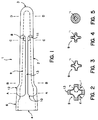
- the nozzle (1) comprises a generally tubular body (2) having a smoothly rounded distal end (3) and a proximal end (4) having an opening with an internal screw thread fitting (5) within a base part (6) of the nozzle suitable for connecting the proximal end (4) to a squeeze bottle (not shown).
- a channel (7) Internally along the central longitudinal axis of the body (2) is a channel (7), running from the opening at the proximal end (4), to a point near the distal end (3).
- the internal outline of the channel (7) in Fig. 1 is shown by a dotted line.
- apertures (8) In the body (2) of the nozzle are eight apertures (8), communicating with the channel (7) thereby permitting fluid flowing along the channel (7) from the proximal end (4) to the distal end (3) to exit the nozzle.
- the apertures (8) are located in the half of the length of the body (2) closest to the distal end (3), and are symmetrically disposed in two sets each of four apertures around the longitudinal axis of the body (2).
- Each of the apertures (8) is located at the extreme distal end of a longitudinally extending recessed groove (9) in the outer surface of the body (2), the grooves (9) running longitudinally from this extreme distal end to a region (10) on the outer surface of the base part (6) of the body (2) near the proximal end (4).
- the extreme distal end of each groove (9) comprises a wall surface (11), in the form of a generally laterally inclined concave (relative to the aperture) surface formed in the surface of the body of the nozzle, immediately proximally adjacent to each aperture (8).
- the tubular body (2) of the nozzle has a narrower cross section than the base part (6), and the cross section of the body (2) and base part (6) are accommodated by shoulders (12).
- the grooves (9) extend into the shoulders (12).
- the grooves (9) are defined by a generally cruciform cross section of the body (2) in the region of the body (2) occupied by the grooves (9) as shown in Figs. 2 to 5 by the cross sections at the longitudinal points A-A, B-B, C-C and D-D respectively, the grooves (9) being defined by the angle between the arms (13) of the cruciform shape.
- the depth (d) of each groove (9) is around 0.5 of the extrapolated radius (r) of the body (2), and the proportion of the circumference of the body (2) over the region of the body (2) occupied by grooves (9) is about 0.6.
- the cross sectional shape of the internal channel (7) conforms generally to the cross sectional shape of the cruciform-sectioned region of the body (2) occupied by the grooves (9).
- the area of the apertures (8) is greater than the cross sectional area of the channel (7).
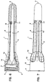
- pans generally corresponding in construction and function to parts of the nozzle of Figs 1 to 7 are numbered correspondingly.
- the apertures (8) are not immediately adjacent to the extreme distal end (11) of the grooves (9) but are at a distance proximally therefrom, typically being within about 0.3 of the length of the groove (9) from the extreme distal end of the groove (9).
- the sections shown in Figs 11 and 20 are enlarged to show that the apertures are located in the surface of the body in a position such that the flow of fluid is diverted into a direction which is substantially parallel to a plane which includes the direction of two oppositely pointing arms (13) of the cruciform section.
- the ratio total area of the apertures : cross sectional area of the longitudinal channel being about 2 : 1 in Figs. 8 to 13 and about 1.07 : 1 in Figs 14 to 21.
- the grooves (9) have a depth of about 0.4 of the extrapolated radius of the body (2) in the vicinity of the apertures (8).
- the body 2 has an overall proximal to distal taper.
- the dimensions of the nozzle shown in Figs. 1 to 21 may be substantially the same as conventional nozzles, the overall length being about 12cm, with a diameter at a median point, e.g the section B-B of Fig. 8 of about 12.5 mm, and an internal diameter at the screw fitting (5) of about 20 mm. Other dimensions of the nozzle illustrated may be determined empirically.
- a squeeze bottle (not shown) containing douche fluid is attached to the open proximal end (4) via the screw thread at (5).
- the body (2) is then inserted for use, and the douche fluid (not shown) is introduced into the channel by squeezing the bottle (not shown).
- Douche fluid exits through the apertures (7) and undergoes a pressure drop as the area of the apertures (8) is greater than the cross sectional area of the channel (7) in the vicinity of the apertures (8).
- the fluid also encounters the diverter surfaces (11) formed by the distal ends of the grooves (9) and as a result the flow is thereby diverted into a distal to proximal direction.
- the deep grooves (9) further encourage the fluid to flow in this direction, and the relative depth (d) of the grooves (9) prevents surrounding tissue from obstructing the flow of douche fluid in the distal to proximal direction.
- the continuation of the grooves (9) into the shoulder (12) and base region (6) assists drainage during use.
Landscapes
- Health & Medical Sciences (AREA)
- General Health & Medical Sciences (AREA)
- Veterinary Medicine (AREA)
- Biomedical Technology (AREA)
- Heart & Thoracic Surgery (AREA)
- Hematology (AREA)
- Life Sciences & Earth Sciences (AREA)
- Animal Behavior & Ethology (AREA)
- Engineering & Computer Science (AREA)
- Anesthesiology (AREA)
- Public Health (AREA)
- Infusion, Injection, And Reservoir Apparatuses (AREA)
- Nozzles (AREA)
- Percussion Or Vibration Massage (AREA)
- Fuel-Injection Apparatus (AREA)
- Coating Apparatus (AREA)
- Massaging Devices (AREA)
- Gas Separation By Absorption (AREA)
Applications Claiming Priority (3)
| Application Number | Priority Date | Filing Date | Title |
|---|---|---|---|
| GB9415840A GB9415840D0 (en) | 1994-08-05 | 1994-08-05 | Nozzle |
| GB9415840 | 1994-08-05 | ||
| PCT/US1995/009587 WO1996004037A1 (en) | 1994-08-05 | 1995-07-28 | Nozzle |
Publications (3)
| Publication Number | Publication Date |
|---|---|
| EP0776229A1 EP0776229A1 (en) | 1997-06-04 |
| EP0776229A4 EP0776229A4 (en) | 1998-04-29 |
| EP0776229B1 true EP0776229B1 (en) | 2003-09-17 |
Family
ID=10759439
Family Applications (1)
| Application Number | Title | Priority Date | Filing Date |
|---|---|---|---|
| EP95927526A Expired - Lifetime EP0776229B1 (en) | 1994-08-05 | 1995-07-28 | Douche nozzle |
Country Status (8)
| Country | Link |
|---|---|
| US (2) | US5695481A (da) |
| EP (1) | EP0776229B1 (da) |
| AT (1) | ATE249858T1 (da) |
| DE (1) | DE69531790T2 (da) |
| DK (1) | DK0776229T3 (da) |
| ES (1) | ES2206517T3 (da) |
| GB (1) | GB9415840D0 (da) |
| WO (1) | WO1996004037A1 (da) |
Families Citing this family (31)
| Publication number | Priority date | Publication date | Assignee | Title |
|---|---|---|---|---|
| US6190365B1 (en) * | 1999-06-21 | 2001-02-20 | Chun Lim Abbott | Vaginal douche applicator and method of vaginal deodorization using the same |
| GB0013514D0 (en) * | 2000-06-02 | 2000-07-26 | Btg Int Ltd | Device for female transient urinary catheterisation |
| US6770060B2 (en) | 2001-09-13 | 2004-08-03 | Timothy Hoenig | Personal hygiene system |
| US8118789B2 (en) * | 2002-02-20 | 2012-02-21 | Abbott Research Group, Inc. | Deodorizer devices and systems for controlling perspiration-related body odor |
| US7270653B2 (en) * | 2002-02-20 | 2007-09-18 | Abbott Research Group | Methods of treating abnormal biological conditions using metal oxides |
| US6589216B1 (en) | 2002-02-20 | 2003-07-08 | Abbott Research Group, Inc. | Vaginal douches, vaginal douche applicators and methods of vaginal douching |
| US20050010174A1 (en) * | 2002-06-04 | 2005-01-13 | Berman Irwin R. | Applicator and methods of applying a substance |
| US9132262B2 (en) * | 2002-06-04 | 2015-09-15 | Irwin R. Berman | Applicator for dispensing a medicinal substance |
| US7141036B2 (en) * | 2002-06-04 | 2006-11-28 | Syringe, Llc | Methods of applying a medicinal substance |
| US7125394B2 (en) * | 2002-06-04 | 2006-10-24 | Syringe, Llc | Applicator for dispensing a medicinal substance |
| CN1739161A (zh) * | 2003-01-13 | 2006-02-22 | 皇家飞利浦电子股份有限公司 | 导航到记录中的内容 |
| DE60321602D1 (de) * | 2003-01-13 | 2008-07-24 | Fisco Tools Ltd | Messband und zugehöriges endstück |
| US7226288B2 (en) | 2003-03-13 | 2007-06-05 | Discus Dental Impressions, Inc. | Apparatus for evacuation of root canal |
| US6997714B1 (en) * | 2003-03-13 | 2006-02-14 | Schoeffel G John | Method and apparatus for evacuation of root canal |
| TWM243503U (en) * | 2003-07-09 | 2004-09-11 | Ruei-Hung Shiu | Cleaning nozzle of closet cleaning device |
| US20050197644A1 (en) * | 2004-03-03 | 2005-09-08 | Waychoff Challen W.Ii | Colon hydrotherapy device |
| US20050271746A1 (en) * | 2004-05-18 | 2005-12-08 | Abbott Chun L | Topical treatments for abnormal biological conditions and method of topically treating such conditions |
| US20090004621A1 (en) * | 2007-06-27 | 2009-01-01 | Nancy Quan | Endodontic Irrigation System |
| WO2009108997A1 (en) * | 2008-03-03 | 2009-09-11 | Mk International Pty Ltd | Catheter with friction reducing surface shaping |
| US8267896B2 (en) * | 2009-12-18 | 2012-09-18 | Tyco Healthcare Group Lp | Surgical instrument cleaning arrangement |
| BR112013003236A2 (pt) * | 2010-08-09 | 2016-05-17 | Innovation Technologies Inc | dispositivo de irrigação de abscesso e método para a irrigação de uma ferida com abscesso |
| US20140074051A1 (en) * | 2012-09-13 | 2014-03-13 | Irwin R. Berman | Applicator for dispensing a medicinal substance |
| US10799690B2 (en) * | 2012-09-13 | 2020-10-13 | Syringe Llc | Applicator for dispensing a medicinal substance and methods associated therewith |
| US9731095B2 (en) * | 2013-03-15 | 2017-08-15 | Progeny Concepts, Llc | Clean intermittent catheter having external flow paths |
| CN108136153B (zh) * | 2015-02-20 | 2020-12-29 | 波特拉索尼医疗股份有限公司 | 改进的导尿管、成套工具及方法 |
| US11351297B2 (en) | 2019-02-11 | 2022-06-07 | Ryan Maaskamp | Paddle shaped medicinal dispenser |
| US12515029B2 (en) | 2019-02-11 | 2026-01-06 | Ryan Maaskamp | Oblong shaped medicinal dispenser |
| US11141575B2 (en) | 2019-02-26 | 2021-10-12 | Ryan Maaskamp | Lipped medicinal applicator |
| KR102451546B1 (ko) * | 2019-11-19 | 2022-10-05 | 석주현 | 세정 효과가 향상된 체내 액체 분사기 |
| US12226273B2 (en) * | 2020-05-04 | 2025-02-18 | Stoma Ventures, LLC | Disposable dental aerosol device |
| US12023460B1 (en) | 2022-08-25 | 2024-07-02 | Surgin, Inc. | Flow directing medicinal applicator |
Family Cites Families (35)
| Publication number | Priority date | Publication date | Assignee | Title |
|---|---|---|---|---|
| US205353A (en) * | 1878-06-25 | Improvement in vaginal syringes | ||
| US1638532A (en) * | 1924-02-02 | 1927-08-09 | Kallmeyer Ernst | Syringe head |
| US2791218A (en) * | 1953-08-20 | 1957-05-07 | Raymond L Nimmo | Douche nozzle |
| US3228396A (en) * | 1962-10-18 | 1966-01-11 | Albert L Potts | Vaginal syringe |
| US3474788A (en) * | 1967-06-05 | 1969-10-28 | Barney G Corbin | Disposable douche device |
| US3512526A (en) * | 1967-11-24 | 1970-05-19 | Sol B Fielding | Sponge sheath for douche tip |
| GB1262926A (en) * | 1968-02-08 | 1972-02-09 | Vincent Raymond Sneider | Disposable syringe |
| US3844284A (en) * | 1973-08-09 | 1974-10-29 | Richardson Merrell Inc | Disposable douche |
| US4014332A (en) * | 1973-08-20 | 1977-03-29 | Sneider Vincent R | Disposable syringes |
| DE2343890A1 (de) * | 1973-08-31 | 1975-03-20 | Agfa Gevaert Ag | Fotografische kamera |
| US3905370A (en) * | 1974-03-28 | 1975-09-16 | Int Paper Co | Disposable douche product |
| US3968797A (en) * | 1974-08-13 | 1976-07-13 | International Paper Company | Disposable douche product |
| US4133313A (en) * | 1975-06-30 | 1979-01-09 | Sneider Vincent R | Expandable syringe |
| US4068662A (en) * | 1975-06-30 | 1978-01-17 | Sneider Vincent R | Accordion-style syringes, douches and attachments therefor |
| US4262669A (en) * | 1976-06-29 | 1981-04-21 | Sneider Vincent R | Accordion-style syringes, douches and attachments therefor |
| US4167186A (en) * | 1977-09-08 | 1979-09-11 | The Purdue Frederick Company | Syringe, such as a vaginal douche, and cannula thereof |
| USD256505S (en) | 1978-06-16 | 1980-08-19 | Strickman Robert L | Vaginal syringe |
| US4200097A (en) * | 1978-08-04 | 1980-04-29 | C. B. Fleet Company Incorporated | Disposable douche |
| US4256107A (en) * | 1979-07-30 | 1981-03-17 | Ruth White | Vaginal cleansing apparatus |
| US4309995A (en) * | 1980-01-28 | 1982-01-12 | Sacco Susan M | Vaginal irrigation apparatus |
| US4318403A (en) * | 1980-07-24 | 1982-03-09 | Sneider Vincent R | Foldable nozzle syringe |
| US4351336A (en) * | 1980-08-04 | 1982-09-28 | Sneider Vincent R | Twist bottle dispenser |
| US4324242A (en) * | 1980-10-03 | 1982-04-13 | Abbott Laboratories | Feminine syringe |
| US4405306A (en) * | 1981-12-08 | 1983-09-20 | Beecham Inc. | Medicated disposable douche product |
| US4405321A (en) * | 1982-02-26 | 1983-09-20 | Budoff Penny W | Douche delivery device |
| DE3363028D1 (en) * | 1982-05-26 | 1986-05-22 | Bruhl Wilhelm | Haemorrhoid treatment stick |
| DE3318257A1 (de) * | 1982-05-26 | 1983-12-01 | Wilhelm Dr. 4902 Bad Salzuflen Brühl | Haemorrhoidenbehandlungsstab |
| US4519794A (en) * | 1983-10-11 | 1985-05-28 | Sneider Vincent R | Valve control of nozzle flow from disposable syringe |
| USD285970S (en) | 1984-01-19 | 1986-09-30 | Beecham Inc. | Flip-up douche bottle |
| USD314238S (en) | 1987-09-15 | 1991-01-29 | Schmid Laboratories Inc. | Nozzle |
| US4894053A (en) * | 1988-08-26 | 1990-01-16 | Reddick David C | Douche apparatus |
| USD319699S (en) | 1988-10-05 | 1991-09-03 | Tambrands, Inc. | Combined douche container and nozzle |
| US4911704A (en) * | 1989-01-23 | 1990-03-27 | Wilbur Dixon | Medicated hygienic device |
| CA2093957A1 (en) * | 1993-04-14 | 1994-10-15 | Burke, Derryl P. | Earlube auditory canal fluid applicator |
| US5380300A (en) * | 1993-08-19 | 1995-01-10 | Smithkline Beecham | Douche nozzle |
-
1994
- 1994-08-05 GB GB9415840A patent/GB9415840D0/en active Pending
-
1995
- 1995-05-19 US US08/445,245 patent/US5695481A/en not_active Expired - Lifetime
- 1995-07-28 DE DE69531790T patent/DE69531790T2/de not_active Expired - Lifetime
- 1995-07-28 WO PCT/US1995/009587 patent/WO1996004037A1/en not_active Ceased
- 1995-07-28 AT AT95927526T patent/ATE249858T1/de active
- 1995-07-28 ES ES95927526T patent/ES2206517T3/es not_active Expired - Lifetime
- 1995-07-28 DK DK95927526T patent/DK0776229T3/da active
- 1995-07-28 EP EP95927526A patent/EP0776229B1/en not_active Expired - Lifetime
-
1997
- 1997-07-23 US US08/899,373 patent/US6235008B1/en not_active Expired - Lifetime
Also Published As
| Publication number | Publication date |
|---|---|
| DK0776229T3 (da) | 2003-12-22 |
| ES2206517T3 (es) | 2004-05-16 |
| DE69531790T2 (de) | 2004-07-01 |
| US5695481A (en) | 1997-12-09 |
| GB9415840D0 (en) | 1994-09-28 |
| ATE249858T1 (de) | 2003-10-15 |
| EP0776229A1 (en) | 1997-06-04 |
| HK1012299A1 (en) | 1999-07-30 |
| US6235008B1 (en) | 2001-05-22 |
| DE69531790D1 (de) | 2003-10-23 |
| WO1996004037A1 (en) | 1996-02-15 |
| EP0776229A4 (en) | 1998-04-29 |
Similar Documents
| Publication | Publication Date | Title |
|---|---|---|
| EP0776229B1 (en) | Douche nozzle | |
| US4995865A (en) | Multi-lumen catheters | |
| US4211233A (en) | Urethral catheter | |
| US4167186A (en) | Syringe, such as a vaginal douche, and cannula thereof | |
| CA2237574C (en) | Tapered and reinforced catheter | |
| CA1264132A (en) | Colonic irrigator | |
| US6213633B1 (en) | Mixing and dispensing device | |
| CN121668527A (zh) | 具有流动转向特征部的静脉接入设备和外周静脉导管 | |
| US20100249716A1 (en) | Single-Use Ampoule | |
| US4551130A (en) | Surgical drainage and irrigation apparatus for post operative patient care | |
| KR20130098327A (ko) | 농양 세척을 위한 디바이스 및 방법 | |
| US20050004533A1 (en) | Device and method for rectal lavage | |
| US12246138B2 (en) | Liquid medication-injecting urinary catheter | |
| CA2196798C (en) | Nozzle | |
| US4248228A (en) | Disposable enema syringe for one hand use | |
| HK1012299B (en) | Douche nozzle | |
| CA1329080C (en) | Rectal insertion device and control valve means therefor | |
| EP0098688A1 (en) | Intratubular medication dispenser | |
| US6918517B2 (en) | Nozzle for a sanitary cleansing device | |
| CN220344929U (zh) | 一次性给药装置挤入器 | |
| EP2247257B1 (en) | Teat needle with protective end wall | |
| KR102732287B1 (ko) | 화장료 튜브용기용 배출구 및 이를 포함하는 화장료 튜브용기 | |
| US20050010174A1 (en) | Applicator and methods of applying a substance | |
| EP0471836A1 (en) | BOTTLE SYSTEM PROVIDED WITH A FIRST REMOVABLE CAP AND A THREADED CLOSURE CAP. | |
| CN213130813U (zh) | 便于挤压的灌肠剂瓶 |
Legal Events
| Date | Code | Title | Description |
|---|---|---|---|
| PUAI | Public reference made under article 153(3) epc to a published international application that has entered the european phase |
Free format text: ORIGINAL CODE: 0009012 |
|
| 17P | Request for examination filed |
Effective date: 19970228 |
|
| AK | Designated contracting states |
Kind code of ref document: A1 Designated state(s): AT BE CH DE DK ES FR GB IT LI NL SE |
|
| A4 | Supplementary search report drawn up and despatched |
Effective date: 19980311 |
|
| AK | Designated contracting states |
Kind code of ref document: A4 Designated state(s): AT BE CH DE DK ES FR GB IT LI NL SE |
|
| 17Q | First examination report despatched |
Effective date: 20020327 |
|
| RTI1 | Title (correction) |
Free format text: DOUCHE NOZZLE |
|
| GRAH | Despatch of communication of intention to grant a patent |
Free format text: ORIGINAL CODE: EPIDOS IGRA |
|
| GRAH | Despatch of communication of intention to grant a patent |
Free format text: ORIGINAL CODE: EPIDOS IGRA |
|
| GRAA | (expected) grant |
Free format text: ORIGINAL CODE: 0009210 |
|
| RAP1 | Party data changed (applicant data changed or rights of an application transferred) |
Owner name: SMITHKLINE BEECHAM CORPORATION |
|
| AK | Designated contracting states |
Kind code of ref document: B1 Designated state(s): AT BE CH DE DK ES FR GB IT LI NL SE |
|
| REG | Reference to a national code |
Ref country code: GB Ref legal event code: FG4D |
|
| REG | Reference to a national code |
Ref country code: CH Ref legal event code: EP |
|
| REF | Corresponds to: |
Ref document number: 69531790 Country of ref document: DE Date of ref document: 20031023 Kind code of ref document: P |
|
| REG | Reference to a national code |
Ref country code: CH Ref legal event code: NV Representative=s name: ING. MARCO ZARDI C/O M. ZARDI & CO. S.A. |
|
| REG | Reference to a national code |
Ref country code: DK Ref legal event code: T3 |
|
| REG | Reference to a national code |
Ref country code: SE Ref legal event code: TRGR |
|
| REG | Reference to a national code |
Ref country code: ES Ref legal event code: FG2A Ref document number: 2206517 Country of ref document: ES Kind code of ref document: T3 |
|
| ET | Fr: translation filed | ||
| PLBE | No opposition filed within time limit |
Free format text: ORIGINAL CODE: 0009261 |
|
| STAA | Information on the status of an ep patent application or granted ep patent |
Free format text: STATUS: NO OPPOSITION FILED WITHIN TIME LIMIT |
|
| 26N | No opposition filed |
Effective date: 20040618 |
|
| REG | Reference to a national code |
Ref country code: HK Ref legal event code: GR Ref document number: 1012299 Country of ref document: HK |
|
| REG | Reference to a national code |
Ref country code: CH Ref legal event code: PCAR Free format text: ISLER & PEDRAZZINI AG;POSTFACH 1772;8027 ZUERICH (CH) |
|
| PGFP | Annual fee paid to national office [announced via postgrant information from national office to epo] |
Ref country code: DK Payment date: 20110623 Year of fee payment: 17 |
|
| PGFP | Annual fee paid to national office [announced via postgrant information from national office to epo] |
Ref country code: CH Payment date: 20110729 Year of fee payment: 17 |
|
| REG | Reference to a national code |
Ref country code: DE Ref legal event code: R082 Ref document number: 69531790 Country of ref document: DE Representative=s name: HOFFMANN - EITLE, DE Effective date: 20120426 Ref country code: DE Ref legal event code: R081 Ref document number: 69531790 Country of ref document: DE Owner name: MEDTECH PRODUCTS, INC. (N.D. GES. D. STAATES D, US Free format text: FORMER OWNER: SMITHKLINE BEECHAM CORP., KING OF PRUSSIA, US Effective date: 20120426 |
|
| PGFP | Annual fee paid to national office [announced via postgrant information from national office to epo] |
Ref country code: GB Payment date: 20120730 Year of fee payment: 18 Ref country code: SE Payment date: 20120726 Year of fee payment: 18 |
|
| PGFP | Annual fee paid to national office [announced via postgrant information from national office to epo] |
Ref country code: ES Payment date: 20120725 Year of fee payment: 18 Ref country code: FR Payment date: 20120809 Year of fee payment: 18 Ref country code: DE Payment date: 20120726 Year of fee payment: 18 Ref country code: BE Payment date: 20120831 Year of fee payment: 18 Ref country code: IT Payment date: 20120725 Year of fee payment: 18 |
|
| PGFP | Annual fee paid to national office [announced via postgrant information from national office to epo] |
Ref country code: NL Payment date: 20120730 Year of fee payment: 18 |
|
| REG | Reference to a national code |
Ref country code: GB Ref legal event code: 732E Free format text: REGISTERED BETWEEN 20130228 AND 20130306 |
|
| PGFP | Annual fee paid to national office [announced via postgrant information from national office to epo] |
Ref country code: AT Payment date: 20120731 Year of fee payment: 18 |
|
| BERE | Be: lapsed |
Owner name: *SMITHKLINE BEECHAM CORP. Effective date: 20130731 |
|
| REG | Reference to a national code |
Ref country code: NL Ref legal event code: V1 Effective date: 20140201 |
|
| REG | Reference to a national code |
Ref country code: DK Ref legal event code: EBP Effective date: 20130731 |
|
| REG | Reference to a national code |
Ref country code: CH Ref legal event code: PL |
|
| REG | Reference to a national code |
Ref country code: SE Ref legal event code: EUG |
|
| REG | Reference to a national code |
Ref country code: AT Ref legal event code: MM01 Ref document number: 249858 Country of ref document: AT Kind code of ref document: T Effective date: 20130728 |
|
| GBPC | Gb: european patent ceased through non-payment of renewal fee |
Effective date: 20130728 |
|
| REG | Reference to a national code |
Ref country code: DE Ref legal event code: R119 Ref document number: 69531790 Country of ref document: DE Effective date: 20140201 |
|
| REG | Reference to a national code |
Ref country code: FR Ref legal event code: ST Effective date: 20140331 |
|
| PG25 | Lapsed in a contracting state [announced via postgrant information from national office to epo] |
Ref country code: SE Free format text: LAPSE BECAUSE OF NON-PAYMENT OF DUE FEES Effective date: 20130729 Ref country code: CH Free format text: LAPSE BECAUSE OF NON-PAYMENT OF DUE FEES Effective date: 20130731 Ref country code: BE Free format text: LAPSE BECAUSE OF NON-PAYMENT OF DUE FEES Effective date: 20130731 Ref country code: GB Free format text: LAPSE BECAUSE OF NON-PAYMENT OF DUE FEES Effective date: 20130728 Ref country code: LI Free format text: LAPSE BECAUSE OF NON-PAYMENT OF DUE FEES Effective date: 20130731 Ref country code: NL Free format text: LAPSE BECAUSE OF NON-PAYMENT OF DUE FEES Effective date: 20140201 Ref country code: DE Free format text: LAPSE BECAUSE OF NON-PAYMENT OF DUE FEES Effective date: 20140201 |
|
| PG25 | Lapsed in a contracting state [announced via postgrant information from national office to epo] |
Ref country code: IT Free format text: LAPSE BECAUSE OF NON-PAYMENT OF DUE FEES Effective date: 20130728 Ref country code: FR Free format text: LAPSE BECAUSE OF NON-PAYMENT OF DUE FEES Effective date: 20130731 Ref country code: AT Free format text: LAPSE BECAUSE OF NON-PAYMENT OF DUE FEES Effective date: 20130728 |
|
| REG | Reference to a national code |
Ref country code: ES Ref legal event code: FD2A Effective date: 20140807 |
|
| PG25 | Lapsed in a contracting state [announced via postgrant information from national office to epo] |
Ref country code: DK Free format text: LAPSE BECAUSE OF NON-PAYMENT OF DUE FEES Effective date: 20130731 |
|
| PG25 | Lapsed in a contracting state [announced via postgrant information from national office to epo] |
Ref country code: ES Free format text: LAPSE BECAUSE OF NON-PAYMENT OF DUE FEES Effective date: 20130729 |