EP0775868B1 - Gas burner for a furnace for reheating steel industry products - Google Patents
Gas burner for a furnace for reheating steel industry products Download PDFInfo
- Publication number
- EP0775868B1 EP0775868B1 EP96402273A EP96402273A EP0775868B1 EP 0775868 B1 EP0775868 B1 EP 0775868B1 EP 96402273 A EP96402273 A EP 96402273A EP 96402273 A EP96402273 A EP 96402273A EP 0775868 B1 EP0775868 B1 EP 0775868B1
- Authority
- EP
- European Patent Office
- Prior art keywords
- burner
- gas
- furnace
- air
- orifices
- Prior art date
- Legal status (The legal status is an assumption and is not a legal conclusion. Google has not performed a legal analysis and makes no representation as to the accuracy of the status listed.)
- Expired - Lifetime
Links
- 229910000831 Steel Inorganic materials 0.000 title claims description 18
- 239000010959 steel Substances 0.000 title claims description 18
- 238000003303 reheating Methods 0.000 title claims description 9
- 238000011144 upstream manufacturing Methods 0.000 claims description 4
- XEEYBQQBJWHFJM-UHFFFAOYSA-N Iron Chemical compound [Fe] XEEYBQQBJWHFJM-UHFFFAOYSA-N 0.000 claims 6
- 229910052742 iron Inorganic materials 0.000 claims 3
- 239000007789 gas Substances 0.000 description 38
- 238000010438 heat treatment Methods 0.000 description 21
- VNWKTOKETHGBQD-UHFFFAOYSA-N methane Chemical compound C VNWKTOKETHGBQD-UHFFFAOYSA-N 0.000 description 14
- MWUXSHHQAYIFBG-UHFFFAOYSA-N Nitric oxide Chemical compound O=[N] MWUXSHHQAYIFBG-UHFFFAOYSA-N 0.000 description 9
- 238000002485 combustion reaction Methods 0.000 description 8
- 239000003345 natural gas Substances 0.000 description 7
- 230000005855 radiation Effects 0.000 description 5
- 239000000446 fuel Substances 0.000 description 4
- 239000000779 smoke Substances 0.000 description 3
- 239000002737 fuel gas Substances 0.000 description 2
- 239000000203 mixture Substances 0.000 description 2
- 238000013021 overheating Methods 0.000 description 2
- 238000000926 separation method Methods 0.000 description 2
- 238000005054 agglomeration Methods 0.000 description 1
- 230000002776 aggregation Effects 0.000 description 1
- QVGXLLKOCUKJST-UHFFFAOYSA-N atomic oxygen Chemical compound [O] QVGXLLKOCUKJST-UHFFFAOYSA-N 0.000 description 1
- 230000008033 biological extinction Effects 0.000 description 1
- 229910010293 ceramic material Inorganic materials 0.000 description 1
- 239000000571 coke Substances 0.000 description 1
- 239000000567 combustion gas Substances 0.000 description 1
- 230000004907 flux Effects 0.000 description 1
- 239000003517 fume Substances 0.000 description 1
- 230000003116 impacting effect Effects 0.000 description 1
- 238000004519 manufacturing process Methods 0.000 description 1
- 239000001301 oxygen Substances 0.000 description 1
- 229910052760 oxygen Inorganic materials 0.000 description 1
- 238000005096 rolling process Methods 0.000 description 1
- 238000007789 sealing Methods 0.000 description 1
Images

Classifications
-
- F—MECHANICAL ENGINEERING; LIGHTING; HEATING; WEAPONS; BLASTING
- F23—COMBUSTION APPARATUS; COMBUSTION PROCESSES
- F23D—BURNERS
- F23D14/00—Burners for combustion of a gas, e.g. of a gas stored under pressure as a liquid
- F23D14/20—Non-premix gas burners, i.e. in which gaseous fuel is mixed with combustion air on arrival at the combustion zone
- F23D14/22—Non-premix gas burners, i.e. in which gaseous fuel is mixed with combustion air on arrival at the combustion zone with separate air and gas feed ducts, e.g. with ducts running parallel or crossing each other
- F23D14/24—Non-premix gas burners, i.e. in which gaseous fuel is mixed with combustion air on arrival at the combustion zone with separate air and gas feed ducts, e.g. with ducts running parallel or crossing each other at least one of the fluids being submitted to a swirling motion
-
- F—MECHANICAL ENGINEERING; LIGHTING; HEATING; WEAPONS; BLASTING
- F23—COMBUSTION APPARATUS; COMBUSTION PROCESSES
- F23C—METHODS OR APPARATUS FOR COMBUSTION USING FLUID FUEL OR SOLID FUEL SUSPENDED IN A CARRIER GAS OR AIR
- F23C9/00—Combustion apparatus characterised by arrangements for returning combustion products or flue gases to the combustion chamber
- F23C9/006—Combustion apparatus characterised by arrangements for returning combustion products or flue gases to the combustion chamber the recirculation taking place in the combustion chamber
-
- F—MECHANICAL ENGINEERING; LIGHTING; HEATING; WEAPONS; BLASTING
- F23—COMBUSTION APPARATUS; COMBUSTION PROCESSES
- F23M—CASINGS, LININGS, WALLS OR DOORS SPECIALLY ADAPTED FOR COMBUSTION CHAMBERS, e.g. FIREBRIDGES; DEVICES FOR DEFLECTING AIR, FLAMES OR COMBUSTION PRODUCTS IN COMBUSTION CHAMBERS; SAFETY ARRANGEMENTS SPECIALLY ADAPTED FOR COMBUSTION APPARATUS; DETAILS OF COMBUSTION CHAMBERS, NOT OTHERWISE PROVIDED FOR
- F23M5/00—Casings; Linings; Walls
- F23M5/02—Casings; Linings; Walls characterised by the shape of the bricks or blocks used
- F23M5/025—Casings; Linings; Walls characterised by the shape of the bricks or blocks used specially adapted for burner openings
Definitions
- the present invention relates to a gas burner, of the type used. in furnaces for heating steel products, such as slabs for example.
- These burners are high power burners, supplied with particularly in steel gas (mixed gas, coke oven gas for example), and are arranged in the roof of the heating furnaces.
- burners of this kind which generally have several concentric channels fuel gas and air supply, opening at the nose of the burner, downstream of which combustion occurs.
- burners of the type "jet burner” very high gas ejection speed, greater than 100 meters per second.
- the air and the combustion gas burn in the combustion chamber combustion of the burner, and at the burner outlet, we are in the presence of hot smoke, combustion is complete.
- This type of burner is commonly used in ovens requiring direct heating of products, for example in hoods caking agglomeration, because the very high gas ejection speed allows to heat a very localized area.
- Such a type of burner is not suitable for furnaces reheating of steel products because the heating they provide is very localized direct heating. Their use would cause temperature heterogeneity on the product to be heated with risk important appearance of black streaks and risk of causing problems during the subsequent rolling operation (in the case of reheating the slabs).
- the flame due to the combustion of the air / gas mixture is generated downstream of the burner nose, in the burner, i.e. in the housing fitted into the internal lining of the oven and into which the burner.
- This tulip-shaped workpiece allows you to tackle the flame against the walls of said opener and against the walls of the roof of the oven.
- the weak gas impulse in this type of burner leads to poor mixing of the fumes inside the oven and thus heterogeneity of temperatures between the oven roof and the product steel to be heated.
- this type of burner by design, has a flared flat flame and therefore a certain black hole in the center of said flame, where it does not generate a flame. This phenomenon reinforces the problem of temperature heterogeneity.
- this type of burner is not multi-fuel. he is only intended to operate on steel gas and cannot be suitable for running on natural gas.
- This type of burner requires a tulip-shaped burner, it is relatively expensive to operate due to the high cost of this type of workman. In addition, this type of workman is relatively fragile.
- this type of burner has a low efficiency thermal, in the sense of its capacity to generate a rise in temperature in the oven, because the useful heating surface on the roof of the oven of each burner is relatively small.
- the flame due to the combustion of the air / gas mixture is generated downstream of the burner nose, into the burner, in the form of a ball.
- a big disadvantage of this type of burner is its very low adjustment latitude in terms of heating power.
- This type of burner has three series of orifices, a first for the passage of gas, a second for the passage of air, arranged in circle around the gas passage openings, generating a short flame, with a length of the order of 2 meters, and a third series of orifices for the air passage, located at the periphery, generating a long flame, of a length of the order of 4.5 meters.
- This type of burner is a burner for direct heating of steel products. There is therefore a drawback related to this function, to know the heterogeneity of temperatures in the product to be heated, certainly less important than in the case of "jet burners".
- the object of the present invention is to propose a burner combining direct heating and indirect heating by radiation of the roof of the furnace, having a great latitude of adjustment of the power of heats, allowing to generate a homogeneous temperature of the roof of the furnace, which can use both steel and natural gas, while not producing too much nitrogen oxide.
- the present invention also relates to an oven roof of reheating of steel products, characterized in that it comprises at least one housing 9, cylindrical with diameter D3, arranged in the internal lining of the oven roof, in which a burner is kept according to the preceding claims, and in that the ratio between the diameter D2 of the crown of the orifices for the passage of air from the burner and the diameter D3 of the housing 9 is between 0.6 and 0.8, preferably equal at 0.68.
- the ratio between the diameter D3 housing fitted in the internal lining of the oven roof and the distance between the front surface of the burner nose and the top of the oven is between 0.9 and 1, preferably equal to 0.95.
- the burner 1 includes a gas supply box 2 fuel and air, formed of a central gas supply channel 3, oriented in the axial direction X of the burner, surrounded by an annular channel 4 air intake.
- the burner 1 also includes a nose 7 also called diffuser, generally made of a ceramic material.
- the nose 7 consists of a thick plate 8 which covers the axial ends of the different channels while ensuring sealing between them, and which is inserted into a housing 9, cylindrical with diameter D3, fitted into the internal lining of the oven roof, being there held by fixing means, not shown, on the wall of the oven.
- the upstream face of the burner nose 7 has a surface frontal 13 flat, facing the interior of the oven.
- the plate 8 of the burner nose 7 is traversed by a plurality gas and air outlet ports.
- the orifices 10, connected to the gas supply channel 3 are coaxial to the axial direction X of the burner.
- the plate 8 of the nose 7 of the burner is provided with six orifices 10, also distributed in a circle on the crown C1.
- the orifices 12, connected to the channel 4 air supply are made so that the axis of each orifice either located in a plane parallel to the axial direction of the burner and tangent to the crown C2, and inclined in this plane, by an angle ⁇ with respect to said axial direction.
- the angle ⁇ is between 15 and 25 °.
- the orifices 12 are therefore oriented in a helix, so that the escaping air flow has a rotational movement around the X axis of the burner, creating a swirling air flow causing depression which sucks in the gas flow.
- the plate 8 of the nose 7 of the burner is provided with eight orifices 12, also distributed in a circle on the crown C2.
- the burner nose 7 has a portion 14 recessed towards the interior of the burner with respect to the substantially planar front surface 13, perpendicular to the X axis of the burner, into which the orifices 10 open gas passage and the air passage orifices 12, the recessed part 14 and the front surface 13 being interconnected by a connecting surface 15.
- the connecting surface 15 between the front surface 13 and the part set back 14 from the upstream face of the burner nose is substantially in the form of truncated cone, the large base of which is located at the level of the frontal surface 13.
- the angle ⁇ of the truncated cone of the connecting surface 15 is between 20 and 40 °, preferably equal to 30 °.
- the D1 / D2 ratio of crowns C1 and C2, respectively of the series of orifices 10 of gas passage and the series of air passage holes is included between 0.4 and 0.5.
- this ratio D1 / D2 is less than 0.4, the flame is of the type "jet", impacting directly on the product, and when using gas natural, there is separation of the flame and risk of extinction. If this report is greater than 0.5, the flame is very short, disturbed, and there is overheating of the workman, especially if you use natural gas.
- the ratio between the diameter D2 of the crown C2 of the series of air passage holes 12 and the diameter D3 of the housing 9 fitted in the internal lining of the oven roof is between 0.6 and 0.8.
- this ratio D2 / D3 is less than 0.6, a flame is produced soft, poorly directed, sensitive to variations in the internal pressure of the oven. If this ratio is greater than 0.8, the flame is an airplane nozzle type torch, it there is a strong separation of the flame if natural gas is used, and at high flow the flame is blown out for all types of gas.
- the relationship between the diameter D3 of the fitted housing 9 in the internal lining of the oven roof and the distance H between the front surface 13 of the burner nose and the top of the oven is between 0.9 and 1.
- This configuration allows the flame to develop in the housing 9 arranged in the roof of the oven. This flame is not directly pressed against the wall of the oven roof, but develops at the interior of the oven in the form of a very obtuse angle cone, of the order of 160 to 170 °.
- the flame develops inside the oven more or less pressed against the wall of the vault of the oven.
- a ratio of diameters D1 / D2 equal to 0.40 or equal to 0.50 ensures that the burner will effectively combine the function direct heating and indirect heating by radiation of the oven roof.
- a D1 / D2 ratio of 0.43 is very close to ideal if a steel gas is used, but is not completely satisfactory if you use natural gas.
- a D1 / D2 ratio of 0.48 is very close to ideal for natural gas, but causes flames if using a gas mixed at high flow and produces too much NOx.
- the relationship between the diameter D3 and the distance H is optimum when it is between 0.93 and 0.97, preferably equal to 0.95.
- Such a burner makes it possible to obtain heating of the furnace according to two combined modes, direct heating and indirect radiant heating, and this at from a gas ejection speed equal to 40 meters per second.
- Such a burner can thus operate with an ejection speed gases from 40 to 100 meters per second, which gives it great latitude to adjust the heating power, while ensuring homogeneous arch temperature.
- Such a burner is multi-fuel, that is to say that it retains its properties regardless of the type of gas used, from natural gas to steel gas.
Landscapes
- Engineering & Computer Science (AREA)
- Chemical & Material Sciences (AREA)
- Combustion & Propulsion (AREA)
- Mechanical Engineering (AREA)
- General Engineering & Computer Science (AREA)
- Gas Burners (AREA)
- Pre-Mixing And Non-Premixing Gas Burner (AREA)
- Furnace Details (AREA)
Abstract
Description
La présente invention concerne un brûleur à gaz, du type utilisé dans les fours de réchauffage de produits sidérurgiques, tels que des fours à brames par exemple.The present invention relates to a gas burner, of the type used. in furnaces for heating steel products, such as slabs for example.
Ces brûleurs sont des brûleurs de forte puissance, alimentés en particulier en gaz sidérurgique (gaz mixte, gaz de fours à coke par exemple), et sont disposés dans la voûte des fours de réchauffage.These burners are high power burners, supplied with particularly in steel gas (mixed gas, coke oven gas for example), and are arranged in the roof of the heating furnaces.
On connaít déjà différents types de brûleurs de ce genre, qui comportent de manière générale plusieurs canaux concentriques d'alimentation en gaz combustible et en air, débouchant au niveau du nez du brûleur, en aval duquel se produit la combustion.We already know different types of burners of this kind, which generally have several concentric channels fuel gas and air supply, opening at the nose of the burner, downstream of which combustion occurs.
Par exemple, on connaít des brûleurs du type "brûleur jet" à très haute vitesse d'éjection des gaz, supérieure à 100 mètres par seconde. Dans ce type de brûleurs, l'air et le gaz de combustion brûlent dans la chambre de combustion du brûleur, et à la sortie du brûleur, on est en présence de fumées chaudes, la combustion étant terminée.For example, we know burners of the type "jet burner" very high gas ejection speed, greater than 100 meters per second. In this type of burner, the air and the combustion gas burn in the combustion chamber combustion of the burner, and at the burner outlet, we are in the presence of hot smoke, combustion is complete.
Ce type de brûleur est couramment utilisé dans les fours nécessitant un chauffage direct des produits, par exemple dans les hottes d'agglomération du coke, car la très grande vitesse d'éjection des gaz permet de chauffer une zone très localisée.This type of burner is commonly used in ovens requiring direct heating of products, for example in hoods caking agglomeration, because the very high gas ejection speed allows to heat a very localized area.
Un tel type de brûleur ne convient pas pour les fours de réchauffage des produits sidérurgiques car le chauffage qu'ils procurent est un chauffage direct très localisé. Leur utilisation provoquerait des hétérogénéité de température sur le produit à réchauffer avec risque important d'apparition de traces noires et risques d'engendrer des problèmes lors de l'opération de laminage ultérieur (dans le cas du réchauffage des brames).Such a type of burner is not suitable for furnaces reheating of steel products because the heating they provide is very localized direct heating. Their use would cause temperature heterogeneity on the product to be heated with risk important appearance of black streaks and risk of causing problems during the subsequent rolling operation (in the case of reheating the slabs).
On connaít également les brûleurs dits "à flamme plate" ou dits "à flamme plane". Dans ce type de brûleur, l'air de combustion est amené en rotation autour de l'amenée de gaz. Le document EP-A-0 674 135 montre un tel brûleur.We also know the burners called "flat flame" or so-called "flat flame". In this type of burner, the combustion air is brought in rotation around the gas supply. Document EP-A-0 674 135 shows such a burner.
La flamme due à la combustion du mélange air/gaz est générée en aval du nez du brûleur, dans l'ouvreau, c'est à dire dans le logement aménagé dans le revêtement interne du four et dans lequel est inséré le brûleur. The flame due to the combustion of the air / gas mixture is generated downstream of the burner nose, in the burner, i.e. in the housing fitted into the internal lining of the oven and into which the burner.
Cet ouvreau, en forme de tulipe, permet de plaquer la flamme contre les parois dudit ouvreau et contre les parois de la voûte du four.This tulip-shaped workpiece allows you to tackle the flame against the walls of said opener and against the walls of the roof of the oven.
Ce type de brûleur, permettant un chauffage indirect du produit par rayonnement de la voûte du four, présente un certain nombre d'inconvénients.This type of burner, allowing indirect heating of the product by radiation from the roof of the oven, presents a number disadvantages.
D'une part, la faible impulsion des gaz dans ce type de brûleur entraíne un mauvais brassage des fumées à l'intérieur du four et ainsi une hétérogénéité de températures entre la voûte du four et le produit sidérurgique à réchauffer.On the one hand, the weak gas impulse in this type of burner leads to poor mixing of the fumes inside the oven and thus heterogeneity of temperatures between the oven roof and the product steel to be heated.
De plus ce type de brûleur, de par sa conception, présente une flamme plate évasée et donc un certain trou noir au centre de ladite flamme, endroit où il ne génère pas de flamme. Ce phénomène vient renforcer le problème de l'hétérogénéité des températures.In addition, this type of burner, by design, has a flared flat flame and therefore a certain black hole in the center of said flame, where it does not generate a flame. This phenomenon reinforces the problem of temperature heterogeneity.
Ce problème de l'hétérogénéité des températures est très important car le chauffage du produit sidérurgique s'effectuant par rayonnement de la chaleur emmagasinée dans la voûte du four, toute hétérogénéité de température sur la voûte se répercute sur le produit sidérurgique.This problem of temperature heterogeneity is very important because the heating of the steel product is effected by radiation of the heat stored in the roof of the oven, all temperature heterogeneity on the vault affects the product steel.
D'autre part, ce type de brûleur n'est pas multi-combustible. Il n'est prévu que pour fonctionner au gaz sidérurgique et ne peut pas être adapté pour fonctionner au gaz naturel.On the other hand, this type of burner is not multi-fuel. he is only intended to operate on steel gas and cannot be suitable for running on natural gas.
Ce type de brûleur nécessitant un ouvreau en forme de tulipe, il s'avère relativement coûteux en exploitation du fait du coût élevé de ce type d'ouvreau. De plus ce type d'ouvreau est relativement fragile.This type of burner requires a tulip-shaped burner, it is relatively expensive to operate due to the high cost of this type of workman. In addition, this type of workman is relatively fragile.
Enfin, ce type de brûleur présente un faible rendement thermique, au sens de sa capacité à engendrer une montée en température dans le four, car la surface utile de chauffe sur la voûte du four de chaque brûleur est relativement faible.Finally, this type of burner has a low efficiency thermal, in the sense of its capacity to generate a rise in temperature in the oven, because the useful heating surface on the roof of the oven of each burner is relatively small.
On connaít également les brûleurs dits "à flamme boule" au sein desquels la flamme se développe dans l'ouvreau sous forme d'une boule.We also know the so-called "ball flame" burners within from which the flame develops in the opening in the form of a ball.
La flamme due à la combustion du mélange air/gaz est générée en aval du nez du brûleur, dans l'ouvreau, sous la forme d'une boule.The flame due to the combustion of the air / gas mixture is generated downstream of the burner nose, into the burner, in the form of a ball.
Un grand inconvénient de ce type de brûleur réside dans sa très faible latitude de réglage du point de vue de la puissance de chauffe.A big disadvantage of this type of burner is its very low adjustment latitude in terms of heating power.
On connaít encore des brûleurs à chauffe directe et à longueur de flamme variable. We still know burners direct heating and length of variable flame.
Ce type de brûleur présente trois séries d'orifices, une première pour le passage du gaz, une seconde pour le passage d'air, disposés en cercle autour des orifices de passage du gaz, générant une flamme courte, d'une longueur de l'ordre de 2 mètres, et une troisième série d'orifices pour le passage d'air, situés à la périphérie, générant une flamme longue, d'une longueur de l'ordre de 4,5 mètres.This type of burner has three series of orifices, a first for the passage of gas, a second for the passage of air, arranged in circle around the gas passage openings, generating a short flame, with a length of the order of 2 meters, and a third series of orifices for the air passage, located at the periphery, generating a long flame, of a length of the order of 4.5 meters.
Ce type de brûleur est un brûleur pour le chauffage direct des produits sidérurgiques. Il présente donc un inconvénient lié à cette fonction, à savoir l'hétérogénéité des températures au niveau du produit à chauffer, certes moins important que dans le cas des "brûleurs jet".This type of burner is a burner for direct heating of steel products. There is therefore a drawback related to this function, to know the heterogeneity of temperatures in the product to be heated, certainly less important than in the case of "jet burners".
De plus, un grand nombre de types de brûleurs industriels produisent des gaz ayant des teneurs élevées en oxyde d'azote NOx, notamment supérieurs à 300 ppm pour des teneurs en oxygène de l'ordre de 2 % dans les fumées, ce qui est un inconvénient dans la plupart des fours, ainsi que pour l'environnement, ces oxydes d'azote étant rejetés dans l'atmosphère avec les fumées du four.In addition, a large number of types of industrial burners produce gases with high nitrogen oxide NOx contents, in particular greater than 300 ppm for oxygen contents of the order of 2% in smoke, which is a drawback in most ovens, as well as for the environment, these nitrogen oxides being released into the atmosphere with the smoke from the oven.
La présente invention a pour but de proposer un brûleur combinant la fonction chauffage direct et chauffage indirect par rayonnement de la voûte du four, ayant une grande latitude de réglage de la puissance de chauffe, permettant de générer une température homogène de la voûte du four, pouvant utiliser à la fois du gaz sidérurgique et du gaz naturel, tout en ne produisant pas une quantité trop importante d'oxyde d'azote.The object of the present invention is to propose a burner combining direct heating and indirect heating by radiation of the roof of the furnace, having a great latitude of adjustment of the power of heats, allowing to generate a homogeneous temperature of the roof of the furnace, which can use both steel and natural gas, while not producing too much nitrogen oxide.
L'invention à donc pour objet un brûleur à gaz, notamment pour un four de réchauffage de produits sidérurgiques, comportant un canal central d'alimentation en gaz combustible, un canal annulaire concentrique d'alimentation en air et un nez de brûleur, ledit nez de brûleur comportant une surface frontale en regard avec l'intérieur du four et :
- une première série d'orifices pour le passage du gaz, disposés en cercle sur une couronne de diamètre moyen D1 et en communication avec le canal central,
- une seconde série d'orifices pour le passage d'air, disposés en cercle sur une couronne de diamètre moyen D2 autour des orifices de passage de gaz, et en communication avec le canal annulaire d'alimentation en air, les orifices de passage d'air étant orientés en hélice pour créer un flux d'air tourbillonnant provoquant une dépression qui aspire le gaz, caractérisé en ce que :
- les orifices pour le passage du gaz sont coaxiaux à la direction axiale du nez du brûleur,
- le rapport des diamètres D1/D2 des couronnes est compris entre 0,4 et 0,5, de préférence égal à 0,46.
- a first series of orifices for the passage of gas, arranged in a circle on a crown of average diameter D1 and in communication with the central channel,
- a second series of orifices for the passage of air, arranged in a circle on a ring of average diameter D2 around the orifices for the passage of gas, and in communication with the annular air supply channel, the orifices for passage of air being oriented in a helix to create a swirling air flow causing a vacuum which sucks in the gas, characterized in that:
- the orifices for the passage of gas are coaxial with the axial direction of the burner nose,
- the ratio of diameters D1 / D2 of the crowns is between 0.4 and 0.5, preferably equal to 0.46.
Selon d'autres caractéristiques de l'invention,
- le nez du brûleur comporte une partie en retrait vers l'intérieur du brûleur par rapport à la surface frontale du nez, sensiblement plane, perpendiculaire à l'axe du brûleur, dans laquelle débouchent les deux séries d'orifices, la partie en retrait et la surface frontale étant reliées entre elles par une surface de liaison ;
- la surface de liaison entre la surface frontale et la partie en retrait de la face amont du nez du brûleur est sensiblement en forme de tronc de cône, dont la grande base est située au niveau de la surface frontale;
- l'angle du tronc de cône de la partie en retrait est compris entre 20 et 40 degrés, de préférence égal à 30 degrés.
- the burner nose has a part recessed towards the inside of the burner with respect to the front surface of the nose, substantially planar, perpendicular to the axis of the burner, into which the two series of orifices open, the recessed part and the front surface being interconnected by a connecting surface;
- the connection surface between the front surface and the recessed part of the upstream face of the burner nose is substantially in the form of a truncated cone, the large base of which is situated at the level of the front surface;
- the angle of the truncated cone of the recessed part is between 20 and 40 degrees, preferably equal to 30 degrees.
La présente invention concerne également une voûte de four de réchauffage de produits sidérurgiques, caractérisée en ce qu'elle comprend au moins un logement 9, cylindrique de diamètre D3, aménagé dans le revêtement interne de la voûte du four, dans lequel est maintenu un brûleur selon les revendications précédentes, et en ce que le rapport entre le diamètre D2 de la couronne des orifices pour le passage de l'air du brûleur et le diamètre D3 du logement 9 est compris entre 0,6 et 0,8, de préférence égal à 0,68.The present invention also relates to an oven roof of reheating of steel products, characterized in that it comprises at least one housing 9, cylindrical with diameter D3, arranged in the internal lining of the oven roof, in which a burner is kept according to the preceding claims, and in that the ratio between the diameter D2 of the crown of the orifices for the passage of air from the burner and the diameter D3 of the housing 9 is between 0.6 and 0.8, preferably equal at 0.68.
Selon une autre caractéristique, le rapport entre le diamètre D3 du logement aménagé dans le revêtement interne de la voûte du four et la distance entre la surface frontale du nez du brûleur et la voûte du four est compris entre 0,9 et 1, de préférence égale à 0,95.According to another characteristic, the ratio between the diameter D3 housing fitted in the internal lining of the oven roof and the distance between the front surface of the burner nose and the top of the oven is between 0.9 and 1, preferably equal to 0.95.
Les caractéristiques et avantages apparaítront mieux à la suite de la description qui va suivre, donnée uniquement à titre d'exemple, faite en référence aux dessins annexés, dans lesquels :
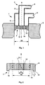
- la figure 1 est une vue en coupe axiale d'un brûleur à gaz selon l'invention, implanté dans la voûte d'un four de réchauffage,
- la figure 2 est une vue en coupe à échelle agrandie du nez du brûleur,
- la figure 3 est une vue frontale du nez du brûleur.
- FIG. 1 is a view in axial section of a gas burner according to the invention, installed in the roof of a reheating oven,
- FIG. 2 is a sectional view on an enlarged scale of the burner nose,
- Figure 3 is a front view of the burner nose.
Le brûleur 1 comporte un caisson 2 d'alimentation en gaz
combustible et en air, formé d'un canal central 3 d'amenée du gaz, orienté
selon la direction axiale X du brûleur, entouré d'un canal annulaire 4
d'amenée d'air.The burner 1 includes a
Ces deux canaux coaxiaux 3, 4 sont alimentés respectivement
en gaz et en air par des conduits d'alimentation 5, 6 respectivement.These two
Le brûleur 1 comporte également un nez 7 encore appelé
diffuseur, généralement réalisé en un matériau céramique.The burner 1 also includes a
Le nez 7 est constitué d'une plaque 8 épaisse qui recouvre les
extrémités axiales des différents canaux en assurant l'étanchéité entre ceux-ci,
et qui est insérée dans un logement 9, cylindrique de diamètre D3,
aménagé dans le revêtement interne de la voûte du four, en y étant
maintenue par des moyens de fixation, non représentés, sur la paroi du four.The
La face amont du nez 7 du brûleur comporte une surface
frontale 13 plane, en regard avec l'intérieur du four.The upstream face of the
La plaque 8 du nez 7 du brûleur est traversée par une pluralité
d'orifices de sortie du gaz et de l'air.The
Une première série d'orifices 10, répartis en cercle sur une
couronne C1, de diamètre moyen D1, débouche du coté de la face arrière 11
de la plaque 8 dans le canal central 3 d'alimentation en gaz.A first series of
Les orifices 10, reliés au canal 3 d'alimentation en gaz sont
coaxiaux à la direction axiale X du brûleur.The
Dans l'exemple de réalisation représenté, la plaque 8 du nez 7
du brûleur est munie de six orifices 10, également répartis en cercle sur la
couronne C1.In the embodiment shown, the
Une seconde série d'orifices 12, répartis en cercle sur une
couronne C2 de diamètre moyen D2 autour des orifices 10, débouche du coté
de la face arrière 11 de la plaque 8 dans le canal annuaire 4 d'alimentation
en air.A second series of
Comme on le voit sur la figure 2, les orifices 12, reliés au canal
4 d'alimentation en air, sont réalisés de manière que l'axe de chaque orifice
soit situé dans un plan parallèle à la direction axiale du brûleur et tangent à la
couronne C2, et incliné dans ce plan, d'un angle α par rapport à ladite
direction axiale.As seen in Figure 2, the
De manière préférentielle, l'angle α est compris entre 15 et 25°. Preferably, the angle α is between 15 and 25 °.
Les orifices 12 sont donc orientés en hélice, de manière que le
flux d'air qui s'en échappe ait un mouvement de rotation autour de l'axe X du
brûleur, créant ainsi un flux d'air tourbillonnant provoquant une dépression
qui aspire le flux de gaz.The
Dans l'exemple de réalisation représenté, la plaque 8 du nez 7
du brûleur est munie de huit orifices 12, également répartis en cercle sur la
couronne C2.In the embodiment shown, the
Le nez 7 du brûleur comporte une partie 14 en retrait vers
l'intérieur du brûleur par rapport à la surface frontale 13, sensiblement plane,
perpendiculaire à l'axe X du brûleur, dans laquelle débouchent les orifices 10
de passage de gaz et les orifices 12 de passage de l'air, la partie en retrait 14
et la surface frontale 13 étant reliées entre elles par une surface de liaison
15.The
La surface de liaison 15 entre la surface frontale 13 et la partie
en retrait 14 de la face amont du nez du brûleur est sensiblement en forme de
tronc de cône, dont la grande base est située au niveau de la surface frontale
13.The connecting
L'angle β du tronc de cône de la surface de liaison 15 est
compris entre 20 et 40°, de préférence égal à 30°.The angle β of the truncated cone of the connecting
Pour assurer que le brûleur selon l'invention combine la fonction
chauffage direct et chauffage indirect par rayonnement de la voûte du four, le
rapport D1/D2 des couronnes C1 et C2, respectivement de la série d'orifices
10 de passage du gaz et de la série d'orifices de passage de l'air est compris
entre 0,4 et 0,5.To ensure that the burner according to the invention combines the function
direct heating and indirect heating by radiation of the oven roof, the
D1 / D2 ratio of crowns C1 and C2, respectively of the series of
Si ce rapport D1/D2 est inférieur à 0,4, la flamme est de type "jet", impactant directement sur le produit, et en cas d'utilisation de gaz naturel, il y a décollement de la flamme et risque d'extinction. Si ce rapport est supérieur à 0,5, la flamme est très courte, perturbée, et il y a surchauffe de l'ouvreau, surtout si on utilise du gaz naturel.If this ratio D1 / D2 is less than 0.4, the flame is of the type "jet", impacting directly on the product, and when using gas natural, there is separation of the flame and risk of extinction. If this report is greater than 0.5, the flame is very short, disturbed, and there is overheating of the workman, especially if you use natural gas.
De plus, le rapport entre le diamètre D2 de la couronne C2 de la série d'orifices 12 de passage de l'air et le diamètre D3 du logement 9 aménagée dans le revêtement interne de la voûte du four est compris entre 0,6 et 0,8.In addition, the ratio between the diameter D2 of the crown C2 of the series of air passage holes 12 and the diameter D3 of the housing 9 fitted in the internal lining of the oven roof is between 0.6 and 0.8.
Si ce rapport D2/D3 est inférieur à 0,6, il se produit une flamme molle, mal dirigée, sensible aux variations de pression interne du four. Si ce rapport est supérieur à 0,8, la flamme est une torche du type tuyère d'avion, il y a un fort décollement de la flamme si on utilise du gaz naturel, et à fort débit la flamme est soufflée pour tout type de gaz.If this ratio D2 / D3 is less than 0.6, a flame is produced soft, poorly directed, sensitive to variations in the internal pressure of the oven. If this ratio is greater than 0.8, the flame is an airplane nozzle type torch, it there is a strong separation of the flame if natural gas is used, and at high flow the flame is blown out for all types of gas.
Enfin, le rapport entre le diamètre D3 du logement 9 aménagée
dans le revêtement interne de la voûte du four et la distance H entre la
surface frontale 13 du nez du brûleur et la voûte du four est compris entre 0,9
et 1.Finally, the relationship between the diameter D3 of the fitted housing 9
in the internal lining of the oven roof and the distance H between the
Si ce rapport D3/H est inférieur à 0,9, il y a surchauffe interne et production trop importante de NOx en cas d'utilisation de gaz sidérurgique. Si ce rapport est supérieur à 1, la flamme est mal dirigée et la combustion est incomplète.If this D3 / H ratio is less than 0.9, there is internal overheating and too much NOx production when using steel gas. Yes this ratio is greater than 1, the flame is badly directed and combustion is incomplete.
Cette configuration permet à la flamme de se développer dans le logement 9 aménagé dans la voûte du four. Cette flamme n'est pas directement plaquée contre la paroi de la voûte du four, mais se développe à l'intérieur du four sous la forme d'un cône d'angle très obtus, de l'ordre de 160 à 170°.This configuration allows the flame to develop in the housing 9 arranged in the roof of the oven. This flame is not directly pressed against the wall of the oven roof, but develops at the interior of the oven in the form of a very obtuse angle cone, of the order of 160 to 170 °.
Selon les valeurs des rapports D1/D2, D2/D3 et D3/H, la flamme se développe à l'intérieur du four plus ou moins plaquée contre la paroi de la voûte du four.According to the values of the ratios D1 / D2, D2 / D3 and D3 / H, the flame develops inside the oven more or less pressed against the wall of the vault of the oven.
Ainsi un rapport des diamètres D1/D2 égal à 0,40 ou égal à 0,50 permet d'assurer que le brûleur combinera effectivement la fonction chauffage direct et chauffage indirect par rayonnement de la voûte du four.Thus a ratio of diameters D1 / D2 equal to 0.40 or equal to 0.50 ensures that the burner will effectively combine the function direct heating and indirect heating by radiation of the oven roof.
Par exemple, un rapport D1/D2 égal à 0,43 est très proche de l'idéal si on utilise un gaz sidérurgique, mais n'est pas totalement satisfaisant si on utilise du gaz naturel.For example, a D1 / D2 ratio of 0.43 is very close to ideal if a steel gas is used, but is not completely satisfactory if you use natural gas.
Un rapport D1/D2 égal à 0,48 par exemple , est très proche de l'idéal pour le gaz naturel, mais provoque des flammèches si on utilise un gaz mixte à fort débit et produit une quantité trop importante de NOx.A D1 / D2 ratio of 0.48, for example, is very close to ideal for natural gas, but causes flames if using a gas mixed at high flow and produces too much NOx.
Le meilleur compromis pour une utilisation multi-combustibles est assuré pour un rapport D1/D2 compris entre 0,44 et 0,48, de préférence égal à 0,46.The best compromise for multi-fuel use is ensured for a D1 / D2 ratio between 0.44 and 0.48, preferably equal to 0.46.
De même, le meilleur compromis concernant le rapport des diamètres D2/D3 est atteint lorsque ce rapport D2/D3 est compris entre 0,66 et 0,70, de préférence égal à 0,68.Similarly, the best compromise regarding the ratio of diameters D2 / D3 is reached when this ratio D2 / D3 is between 0.66 and 0.70, preferably equal to 0.68.
Enfin, le rapport entre le diamètre D3 et la distance H est optimum lorsqu'il est compris entre 0,93 et 0,97, de préférence égal à 0,95. Finally, the relationship between the diameter D3 and the distance H is optimum when it is between 0.93 and 0.97, preferably equal to 0.95.
Un tel brûleur permet d'obtenir un chauffage du four selon deux modes combinés, le chauffage direct et le chauffage indirect radiant, et ceci à partir d'une vitesse d'éjection des gaz égal à 40 mètres par seconde.Such a burner makes it possible to obtain heating of the furnace according to two combined modes, direct heating and indirect radiant heating, and this at from a gas ejection speed equal to 40 meters per second.
Un tel brûleur peut ainsi fonctionner avec une vitesse d'éjection des gaz de 40 à 100 mètres par seconde, ce qui lui confère une grande latitude de réglage de la puissance de chauffe, tout en assurant une température de voûte homogène.Such a burner can thus operate with an ejection speed gases from 40 to 100 meters per second, which gives it great latitude to adjust the heating power, while ensuring homogeneous arch temperature.
De plus, un tel brûleur est multi-combustibles, c'est-à-dire qu'il conserve ses propriétés quel que soit le type de gaz utilisé, du gaz naturel au gaz sidérurgique.In addition, such a burner is multi-fuel, that is to say that it retains its properties regardless of the type of gas used, from natural gas to steel gas.
Claims (7)
- Gas burner, especially for a furnace for reheating iron and steel products, comprising a central combustible-gas-feed channel (3), a concentric annular air-feed channel (4) and a burner head (7), the said burner head (7) having a front surface (13) facing the inside of the furnace and:a first series of holes (10) for passage of the gas, arranged in a circle on a ring (C1) of average diameter D1 and in communication with the central channel (3),a second series of holes (12) for passage of air, arranged in a circle on a ring (C2) of average diameter D2 around the gas passage holes (10) and in communication with the annular air-feed channel (4), the air passage holes (12) being oriented in a helix in order to create a turbulent flow of air causing a partial vacuum which draws in the gas, characterized in that:the holes (10) for passage of the gas are coaxial with the axial direction (X) of the burner head,the ratio of the diameters D1/D2 of the rings (C1) and (C2) is between 0.4 and 0.5.
- Gas burner according to Claim 1, characterized in that the burner head (7) has a part (14) set back towards the inside of the burner with respect to the front surface (13) of the said head, which is approximately plane, perpendicular to the axis of the burner, in which part the two series of holes emerge, the set-back part (14) and the front surface (13) being connected together by a linking surface (15).
- Gas burner according to Claim 2, characterized in that the linking surface (15) between the front surface (13) and the set-back part (14) of the upstream face of the burner head is substantially in the form of a truncated cone, the large base of which is level with the front surface (13).
- Gas burner according to Claim 3, characterized in that the angle β of the truncated cone of the set-back part is between 20 and 40 degrees, preferably equal to 30 degrees.
- Gas burner according to Claim 1, characterized in that the ratio of the diameters D1/D2 of the rings (C1) and (C2) is equal to 0.46.
- Roof of a furnace for reheating iron and steel products, characterized in that it comprises at least one cylindrical housing (9) of diameter D3, made in the internal lining of the roof of the furnace, in which housing a burner according to the preceding claims is held in place and in that the ratio of the diameter D2 of the ring of air passage holes of the burner to the diameter D3 of the housing (9) is between 0.6 and 0.8, preferably equal to 0.68.
- Roof of a furnace for reheating iron and steel products according to Claim 6, characterized in that the ratio of the diameter D3 of the housing (9) to the distance H between the front surface of the burner head and the roof of the furnace is between 0.9 and 1, preferably equal to 0.95.
Applications Claiming Priority (2)
| Application Number | Priority Date | Filing Date | Title |
|---|---|---|---|
| FR9513905 | 1995-11-23 | ||
| FR9513905A FR2741702B1 (en) | 1995-11-23 | 1995-11-23 | GAS BURNER FOR OVEN FOR HEATING STEEL PRODUCTS |
Publications (2)
| Publication Number | Publication Date |
|---|---|
| EP0775868A1 EP0775868A1 (en) | 1997-05-28 |
| EP0775868B1 true EP0775868B1 (en) | 1999-09-22 |
Family
ID=9484838
Family Applications (1)
| Application Number | Title | Priority Date | Filing Date |
|---|---|---|---|
| EP96402273A Expired - Lifetime EP0775868B1 (en) | 1995-11-23 | 1996-10-25 | Gas burner for a furnace for reheating steel industry products |
Country Status (5)
| Country | Link |
|---|---|
| EP (1) | EP0775868B1 (en) |
| AT (1) | ATE184978T1 (en) |
| DE (1) | DE69604366T2 (en) |
| ES (1) | ES2136955T3 (en) |
| FR (1) | FR2741702B1 (en) |
Families Citing this family (7)
| Publication number | Priority date | Publication date | Assignee | Title |
|---|---|---|---|---|
| GB2316161A (en) * | 1996-08-05 | 1998-02-18 | Boc Group Plc | Oxygen-fuel swirl burner |
| ES2159217B1 (en) * | 1998-05-14 | 2002-04-01 | Adiego Tomas Adiego | DEVICE TO AVOID THERMAL LOSSES OF THE CROWN OF FLAMES OF A BURNER. |
| ITMI20020611A1 (en) * | 2002-03-22 | 2003-09-22 | Danieli Off Mecc | BURNER |
| US7549858B2 (en) * | 2006-12-04 | 2009-06-23 | Praxair Technology, Inc. | Combustion with variable oxidant low NOx burner |
| FR2914986B1 (en) * | 2007-04-12 | 2015-04-10 | Saint Gobain Isover | INTERNAL COMBUSTION BURNER |
| DE102008011567B4 (en) * | 2008-02-28 | 2010-01-28 | Corall, Paul, Dipl.-Ing. | Testing device for checking the functionality of smoke extraction systems |
| EP3350513A1 (en) * | 2015-07-31 | 2018-07-25 | Nuvera Fuel Cells, LLC | BURNER ASSEMBLY WITH LOW NOx EMISSIONS |
Family Cites Families (4)
| Publication number | Priority date | Publication date | Assignee | Title |
|---|---|---|---|---|
| FR2193464A5 (en) * | 1972-07-21 | 1974-02-15 | Airco Inc | |
| FR2532405A1 (en) * | 1982-08-25 | 1984-03-02 | Air Liquide | METHOD AND DEVICE FOR ELECTRICALLY IGNITING AN OXYCOMBUSTIBLE BURNER |
| FR2671605A1 (en) * | 1991-01-16 | 1992-07-17 | Lorraine Laminage | AIR AND COMBUSTION GAS MIXER FOR GAS BURNER OF INDUSTRIAL FURNACES. |
| FR2717884B1 (en) * | 1994-03-24 | 1996-06-07 | Lorraine Laminage | Gas burner for industrial ovens. |
-
1995
- 1995-11-23 FR FR9513905A patent/FR2741702B1/en not_active Expired - Fee Related
-
1996
- 1996-10-25 AT AT96402273T patent/ATE184978T1/en not_active IP Right Cessation
- 1996-10-25 EP EP96402273A patent/EP0775868B1/en not_active Expired - Lifetime
- 1996-10-25 ES ES96402273T patent/ES2136955T3/en not_active Expired - Lifetime
- 1996-10-25 DE DE69604366T patent/DE69604366T2/en not_active Expired - Fee Related
Also Published As
| Publication number | Publication date |
|---|---|
| ES2136955T3 (en) | 1999-12-01 |
| DE69604366D1 (en) | 1999-10-28 |
| FR2741702A1 (en) | 1997-05-30 |
| FR2741702B1 (en) | 1997-12-26 |
| DE69604366T2 (en) | 2000-05-11 |
| EP0775868A1 (en) | 1997-05-28 |
| ATE184978T1 (en) | 1999-10-15 |
Similar Documents
| Publication | Publication Date | Title |
|---|---|---|
| US5431559A (en) | Oxygen-fuel burner with staged oxygen supply | |
| EP0674135B1 (en) | Gas burners for industrial furnaces | |
| CA1253745A (en) | Pulverised coal burner | |
| FR2581163A1 (en) | BURNER FOR FLAMBERING STEEL MATERIALS | |
| FR2616520A1 (en) | BURNER SYSTEM IN PARTICULAR AT HIGH SPEED EXIT OF BURNED GASES | |
| FR2601756A1 (en) | BURNER ASSEMBLY OPERATING AT HIGH TEMPERATURE | |
| BE1015604A3 (en) | Method and device for increasing the stability of flame in fireplace coal fog. | |
| EP1907754B1 (en) | Method and installation for unsupported lean fuel gas combustion, using a burner and related burner | |
| CA2053457A1 (en) | Process for heating a thermal chamber and burner | |
| EP0242249B1 (en) | Burner with low polluting-gas emission | |
| EP0775868A1 (en) | Gas burner for a furnacefor reheating steel industry products | |
| US4402666A (en) | Forced draft radiant wall fuel burner | |
| EP0850883A2 (en) | Process for making technical glass and burner for carrying out said method | |
| CA1123285A (en) | Combustion process for liquid fuel and burner for its use | |
| EP0178198B1 (en) | Burner with a priorily mixture and an integrated pilot-flame | |
| FR2780770A1 (en) | RECOVERY DEVICE, RECOVERY APPARATUS FOR BURNER WITH RADIANT TUBE AND DEFLECTOR | |
| EP0003000B1 (en) | Burner head for a combustion chamber | |
| EP1172607B1 (en) | Gas burner with increased power | |
| JP3638170B2 (en) | High temperature furnace oxygen gas burner | |
| FR2570473A1 (en) | Improvements to gas boilers with parallel flow comprising a rose and a flame retention baffle (hub) relating to gas boilers and independent supply of combustion air | |
| EP0499760B1 (en) | Boiler and installation for central heating and/or production of hot water | |
| FR2604241A1 (en) | PROCESS FOR PRODUCING AN OXYGEN ENRICHED FLAME | |
| FR2506897A1 (en) | Furnace gas-burner for efficient short-flame combustion - has gas directed towards inner surface of each distributing pipe by baffle with circumferential openings | |
| JPH06207708A (en) | Gas burner | |
| FR2788838A1 (en) | Burner and method for manufacturing liquid fuel burner has flames leaving from apertures on pipe and facing deflective wall to prevent combustion residue to settle |
Legal Events
| Date | Code | Title | Description |
|---|---|---|---|
| PUAI | Public reference made under article 153(3) epc to a published international application that has entered the european phase |
Free format text: ORIGINAL CODE: 0009012 |
|
| AK | Designated contracting states |
Kind code of ref document: A1 Designated state(s): AT BE CH DE DK ES FI FR GB GR IT LI LU NL PT SE |
|
| 17P | Request for examination filed |
Effective date: 19970616 |
|
| GRAG | Despatch of communication of intention to grant |
Free format text: ORIGINAL CODE: EPIDOS AGRA |
|
| GRAG | Despatch of communication of intention to grant |
Free format text: ORIGINAL CODE: EPIDOS AGRA |
|
| GRAH | Despatch of communication of intention to grant a patent |
Free format text: ORIGINAL CODE: EPIDOS IGRA |
|
| 17Q | First examination report despatched |
Effective date: 19990304 |
|
| GRAH | Despatch of communication of intention to grant a patent |
Free format text: ORIGINAL CODE: EPIDOS IGRA |
|
| GRAA | (expected) grant |
Free format text: ORIGINAL CODE: 0009210 |
|
| AK | Designated contracting states |
Kind code of ref document: B1 Designated state(s): AT BE CH DE DK ES FI FR GB GR IT LI LU NL PT SE |
|
| PG25 | Lapsed in a contracting state [announced via postgrant information from national office to epo] |
Ref country code: SE Free format text: THE PATENT HAS BEEN ANNULLED BY A DECISION OF A NATIONAL AUTHORITY Effective date: 19990922 Ref country code: GR Free format text: LAPSE BECAUSE OF NON-PAYMENT OF DUE FEES Effective date: 19990922 Ref country code: FI Free format text: LAPSE BECAUSE OF NON-PAYMENT OF DUE FEES Effective date: 19990922 |
|
| REF | Corresponds to: |
Ref document number: 184978 Country of ref document: AT Date of ref document: 19991015 Kind code of ref document: T |
|
| REG | Reference to a national code |
Ref country code: CH Ref legal event code: EP |
|
| REF | Corresponds to: |
Ref document number: 69604366 Country of ref document: DE Date of ref document: 19991028 |
|
| ITF | It: translation for a ep patent filed | ||
| REG | Reference to a national code |
Ref country code: ES Ref legal event code: FG2A Ref document number: 2136955 Country of ref document: ES Kind code of ref document: T3 |
|
| GBT | Gb: translation of ep patent filed (gb section 77(6)(a)/1977) |
Effective date: 19991124 |
|
| PG25 | Lapsed in a contracting state [announced via postgrant information from national office to epo] |
Ref country code: PT Free format text: LAPSE BECAUSE OF FAILURE TO SUBMIT A TRANSLATION OF THE DESCRIPTION OR TO PAY THE FEE WITHIN THE PRESCRIBED TIME-LIMIT Effective date: 19991222 Ref country code: DK Free format text: LAPSE BECAUSE OF FAILURE TO SUBMIT A TRANSLATION OF THE DESCRIPTION OR TO PAY THE FEE WITHIN THE PRESCRIBED TIME-LIMIT Effective date: 19991222 |
|
| PLBE | No opposition filed within time limit |
Free format text: ORIGINAL CODE: 0009261 |
|
| STAA | Information on the status of an ep patent application or granted ep patent |
Free format text: STATUS: NO OPPOSITION FILED WITHIN TIME LIMIT |
|
| 26N | No opposition filed | ||
| PG25 | Lapsed in a contracting state [announced via postgrant information from national office to epo] |
Ref country code: LI Free format text: LAPSE BECAUSE OF NON-PAYMENT OF DUE FEES Effective date: 20001031 Ref country code: CH Free format text: LAPSE BECAUSE OF NON-PAYMENT OF DUE FEES Effective date: 20001031 |
|
| REG | Reference to a national code |
Ref country code: CH Ref legal event code: PL |
|
| REG | Reference to a national code |
Ref country code: GB Ref legal event code: IF02 |
|
| PGFP | Annual fee paid to national office [announced via postgrant information from national office to epo] |
Ref country code: GB Payment date: 20020925 Year of fee payment: 7 |
|
| PGFP | Annual fee paid to national office [announced via postgrant information from national office to epo] |
Ref country code: BE Payment date: 20020926 Year of fee payment: 7 |
|
| PGFP | Annual fee paid to national office [announced via postgrant information from national office to epo] |
Ref country code: NL Payment date: 20020930 Year of fee payment: 7 Ref country code: LU Payment date: 20020930 Year of fee payment: 7 |
|
| PGFP | Annual fee paid to national office [announced via postgrant information from national office to epo] |
Ref country code: AT Payment date: 20021003 Year of fee payment: 7 |
|
| PGFP | Annual fee paid to national office [announced via postgrant information from national office to epo] |
Ref country code: FR Payment date: 20021009 Year of fee payment: 7 |
|
| PGFP | Annual fee paid to national office [announced via postgrant information from national office to epo] |
Ref country code: DE Payment date: 20021017 Year of fee payment: 7 |
|
| PGFP | Annual fee paid to national office [announced via postgrant information from national office to epo] |
Ref country code: ES Payment date: 20021022 Year of fee payment: 7 |
|
| PG25 | Lapsed in a contracting state [announced via postgrant information from national office to epo] |
Ref country code: LU Free format text: LAPSE BECAUSE OF NON-PAYMENT OF DUE FEES Effective date: 20031025 Ref country code: GB Free format text: LAPSE BECAUSE OF NON-PAYMENT OF DUE FEES Effective date: 20031025 Ref country code: AT Free format text: LAPSE BECAUSE OF NON-PAYMENT OF DUE FEES Effective date: 20031025 |
|
| PG25 | Lapsed in a contracting state [announced via postgrant information from national office to epo] |
Ref country code: ES Free format text: LAPSE BECAUSE OF NON-PAYMENT OF DUE FEES Effective date: 20031027 |
|
| PG25 | Lapsed in a contracting state [announced via postgrant information from national office to epo] |
Ref country code: BE Free format text: LAPSE BECAUSE OF NON-PAYMENT OF DUE FEES Effective date: 20031031 |
|
| BERE | Be: lapsed |
Owner name: S.A. *SOLLAC Effective date: 20031031 |
|
| PG25 | Lapsed in a contracting state [announced via postgrant information from national office to epo] |
Ref country code: NL Free format text: LAPSE BECAUSE OF NON-PAYMENT OF DUE FEES Effective date: 20040501 Ref country code: DE Free format text: LAPSE BECAUSE OF NON-PAYMENT OF DUE FEES Effective date: 20040501 |
|
| GBPC | Gb: european patent ceased through non-payment of renewal fee |
Effective date: 20031025 |
|
| PG25 | Lapsed in a contracting state [announced via postgrant information from national office to epo] |
Ref country code: FR Free format text: LAPSE BECAUSE OF NON-PAYMENT OF DUE FEES Effective date: 20040630 |
|
| NLV4 | Nl: lapsed or anulled due to non-payment of the annual fee |
Effective date: 20040501 |
|
| REG | Reference to a national code |
Ref country code: FR Ref legal event code: ST |
|
| REG | Reference to a national code |
Ref country code: ES Ref legal event code: FD2A Effective date: 20031027 |
|
| PG25 | Lapsed in a contracting state [announced via postgrant information from national office to epo] |
Ref country code: IT Free format text: LAPSE BECAUSE OF NON-PAYMENT OF DUE FEES;WARNING: LAPSES OF ITALIAN PATENTS WITH EFFECTIVE DATE BEFORE 2007 MAY HAVE OCCURRED AT ANY TIME BEFORE 2007. THE CORRECT EFFECTIVE DATE MAY BE DIFFERENT FROM THE ONE RECORDED. Effective date: 20051025 |