EP0775634A1 - Former for a bag maker and method of producing same - Google Patents
Former for a bag maker and method of producing same Download PDFInfo
- Publication number
- EP0775634A1 EP0775634A1 EP95308427A EP95308427A EP0775634A1 EP 0775634 A1 EP0775634 A1 EP 0775634A1 EP 95308427 A EP95308427 A EP 95308427A EP 95308427 A EP95308427 A EP 95308427A EP 0775634 A1 EP0775634 A1 EP 0775634A1
- Authority
- EP
- European Patent Office
- Prior art keywords
- connecting line
- former
- axial direction
- tubular
- shoulder
- Prior art date
- Legal status (The legal status is an assumption and is not a legal conclusion. Google has not performed a legal analysis and makes no representation as to the accuracy of the status listed.)
- Granted
Links
- 238000000034 method Methods 0.000 title claims description 14
- 239000000463 material Substances 0.000 claims abstract description 29
- 238000005452 bending Methods 0.000 claims abstract description 9
- 238000005520 cutting process Methods 0.000 claims abstract description 7
- 238000004806 packaging method and process Methods 0.000 claims description 9
- 238000007789 sealing Methods 0.000 claims description 7
- 238000004519 manufacturing process Methods 0.000 claims description 3
- 230000000704 physical effect Effects 0.000 description 2
- 238000005266 casting Methods 0.000 description 1
- 238000005516 engineering process Methods 0.000 description 1
- 238000007493 shaping process Methods 0.000 description 1
- 229920001169 thermoplastic Polymers 0.000 description 1
- 239000004416 thermosoftening plastic Substances 0.000 description 1
- 238000003466 welding Methods 0.000 description 1
Images

Classifications
-
- B—PERFORMING OPERATIONS; TRANSPORTING
- B65—CONVEYING; PACKING; STORING; HANDLING THIN OR FILAMENTARY MATERIAL
- B65B—MACHINES, APPARATUS OR DEVICES FOR, OR METHODS OF, PACKAGING ARTICLES OR MATERIALS; UNPACKING
- B65B9/00—Enclosing successive articles, or quantities of material, e.g. liquids or semiliquids, in flat, folded, or tubular webs of flexible sheet material; Subdividing filled flexible tubes to form packages
- B65B9/10—Enclosing successive articles, or quantities of material, in preformed tubular webs, or in webs formed into tubes around filling nozzles, e.g. extruded tubular webs
- B65B9/20—Enclosing successive articles, or quantities of material, in preformed tubular webs, or in webs formed into tubes around filling nozzles, e.g. extruded tubular webs the webs being formed into tubes in situ around the filling nozzles
- B65B9/2014—Tube advancing means
- B65B9/2021—Tube advancing means combined with longitudinal welding devices
-
- B—PERFORMING OPERATIONS; TRANSPORTING
- B65—CONVEYING; PACKING; STORING; HANDLING THIN OR FILAMENTARY MATERIAL
- B65B—MACHINES, APPARATUS OR DEVICES FOR, OR METHODS OF, PACKAGING ARTICLES OR MATERIALS; UNPACKING
- B65B41/00—Supplying or feeding container-forming sheets or wrapping material
- B65B41/12—Feeding webs from rolls
- B65B41/16—Feeding webs from rolls by rollers
-
- B—PERFORMING OPERATIONS; TRANSPORTING
- B65—CONVEYING; PACKING; STORING; HANDLING THIN OR FILAMENTARY MATERIAL
- B65B—MACHINES, APPARATUS OR DEVICES FOR, OR METHODS OF, PACKAGING ARTICLES OR MATERIALS; UNPACKING
- B65B9/00—Enclosing successive articles, or quantities of material, e.g. liquids or semiliquids, in flat, folded, or tubular webs of flexible sheet material; Subdividing filled flexible tubes to form packages
- B65B9/10—Enclosing successive articles, or quantities of material, in preformed tubular webs, or in webs formed into tubes around filling nozzles, e.g. extruded tubular webs
- B65B9/20—Enclosing successive articles, or quantities of material, in preformed tubular webs, or in webs formed into tubes around filling nozzles, e.g. extruded tubular webs the webs being formed into tubes in situ around the filling nozzles
- B65B9/2014—Tube advancing means
- B65B9/2028—Rollers or belts
-
- B—PERFORMING OPERATIONS; TRANSPORTING
- B65—CONVEYING; PACKING; STORING; HANDLING THIN OR FILAMENTARY MATERIAL
- B65B—MACHINES, APPARATUS OR DEVICES FOR, OR METHODS OF, PACKAGING ARTICLES OR MATERIALS; UNPACKING
- B65B9/00—Enclosing successive articles, or quantities of material, e.g. liquids or semiliquids, in flat, folded, or tubular webs of flexible sheet material; Subdividing filled flexible tubes to form packages
- B65B9/10—Enclosing successive articles, or quantities of material, in preformed tubular webs, or in webs formed into tubes around filling nozzles, e.g. extruded tubular webs
- B65B9/20—Enclosing successive articles, or quantities of material, in preformed tubular webs, or in webs formed into tubes around filling nozzles, e.g. extruded tubular webs the webs being formed into tubes in situ around the filling nozzles
- B65B9/22—Forming shoulders; Tube formers
Definitions
- This invention relates to a former for a bag maker and a method of producing such a former. This invention also relates to packaging machines incorporating such a former.
- a bag maker-packaging machine such as a vertical pillow-type form-fill-seal packaging machine as disclosed, for example, in U.S. Patent 5,237,798 issued August 24, 1993, makes use of a component commonly known as a former for bending an elongated flexible bag-making material into a cylindrical form, generally composed of a vertically extending tubular part and a so-called shoulder part (sometimes also called a skirt-like part) having a sloped planar guide section.
- the bag-making material say, in the form of a web, is longitudinally transported towards the former horizontally in a flat form, moves over and along this sloped planar guide section of the shoulder part, changes the direction of its motion sharply as it crosses the connecting line at which the tubular and shoulder parts are attached together so as to move inside the tubular part and is pulled downward axially along the inner surface of the tubular part.
- the bag-making material is pushed upwards first over the sloped planar guide section of the shoulder part, changes the direction of its motion sharply at the connecting line as it is folded into a tubular form, and then is pulled downward by the force not only of the articles which are dropped in to be packaged in the bag being made but also of a pull-down belt or the like (not shown) for causing the motion of the bag-making material.
- the connecting line, at which the bag-making material is forced to change the direction of its motion sharply be a continuous smooth curve shaped correctly because, if it is not shaped correctly or has even a small unevenness, the material is likely to become wrinkled or develop small longitudinal lines on the surface.
- Formers of this type are usually produced by casting, a master mold being used thereafter to carry out an accurate copy process for shaping the connecting line correctly. This, however, requires a long time of hard work by an experienced worker, adding to the production cost, and fluctuations and non-uniformity in the shape of formers make them non-exchangeable. Moreover, many formers are usually required for producing bags of different sizes. Even when bags of the same size are produced, different formers are generally required, depending upon where and how the side edges of the elongated bag-making material should be overlapped for longitudinal sealing. The angle of the sloped planar guide section of the shoulder part must be changed, furthermore, depending on the physical properties of the bag-making material such as its thickness. In short, the cost of equipping a bag maker with a sufficient number of formers with different kinds is substantial if prior art technology is relied upon.
- a former for forming an elongated planar bag-making material into a tubular form comprises a hollow cylindrical tubular part having an inner surface and defining an axial direction; and a shoulder part which has a planar guide section and is connected to said tubular part along a connecting line which surrounds said tubular part such that said material is transported over said planar guide section of said shoulder part, changes direction of motion sharply at said connecting line into said axial direction and is transformed into a tubular form along said inner surface of said tubular part, the angle between the tangent and said connecting line and a plane perpendicular to said axial direction changing at a constant rate.
- This invention provides a method of producing formers of different kinds accurately and automatically.
- This invention also provides formers produced by such a method, having their tubular and shoulder parts formed by bending pieces which are cut from a blank sheet by a numerically controlled cutting machine.
- a former according to the present invention may be characterized not only as being composed of a hollow cylindrical tubular part defining an axial direction and a shoulder part which has a planar guide section and is attached to the tubular part along a closed three-dimensional line (referred to as the connecting line) such that an elongated bag-making material transported over the sloped planar guide section of the shoulder part can be made into a tubular form as it crosses the connecting line to move into the tubular part, but wherein the aforementioned connecting line between the tubular and shoulder parts is shaped such that the angle between its tangent and a plane perpendicular to the axial direction of the tubular part changes at a constant rate with respect to the change in position of the contact point of the tangent with the connecting line, for example, in the direction perpendicular to the axial direction of the tubular part or along the connecting line itself.
- pieces to be made into the tubular and shoulder parts are cut out from a blank sheet in specified geometrical shapes, bent and folded appropriately into predetermined shapes of the tubular and shoulder parts, and attached together, say, by welding, along the aforementioned connecting line.
- the geometrical shapes into which the blank sheet is cut are determined such that, when these pieces are bent, folded and attached together as described above, the connecting line therebetween will satisfy the condition imposed according to this invention as described above regarding the rate of change in its slope.
- side strips of different widths may be provided along the side edges of the pieces to be cut out from the blank sheet.
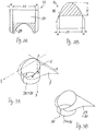
- Fig. 1 shows at 10 an example of formers according to the present invention, comprised essentially, like a prior art former, of a hopper 15, a tubular part 20 and a shoulder part 30 which are attached to each other.
- the three-dimensionally curved closed line along which the tubular part 20 and the shoulder part 30 will be referred to as a connecting line 40 (and also indicated by letter Q).
- a blank sheet material is cut into specified geometrical shapes as shown in Figs. 2A and 2B, bending them and attaching them together.
- the pieces of a blank sheet thus cut out are herein referred to as the tube-forming piece 52 and the shoulder-making piece 53, respectively.
- Fig. 3A shows how the tube-forming piece shown in Fig. 2B may be bent into a tubular form to form the tubular part 20.
- both the tube-forming and shoulder-forming pieces 52 and 53 have a curved edge section 54.
- their curved edge sections 54 become the connecting line 40, along which the tubular and shoulder parts 20 and 30 are attached together.
- the desired shape of the connecting line 40, and the problem of how to determine the shape of the curved edge section 54 when the tube-forming and shoulder-forming pieces 52 and 53 are cut out, will be discussed next.
- the tubular part 20 is of the shape of a cylinder which has been cut by a sloped plane, as shown both in Figs. 1 and 3A.
- the tubular part 20 is standing up vertically, or that it has a vertical axial direction, as shown in Fig. 3A with the highest and lowest points on the connecting line Q indicated by letters O and A, respectively.
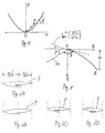
- a three-dimensional rectilinear coordinate system with mutually perpendicular ⁇ , ⁇ and ⁇ -axes is defined, as shown in Fig. 3A, with the origin at O, the ⁇ -axis extending vertically downward, the lowest point A of the connecting line Q being on the ⁇ -plane.
- the ⁇ -plane will be also referred to as the horizontal plane, and the projection of the cylindrical form of the tubular part 20 onto the horizontal plane will be referred to as the cross-section curve.
- Cross-section curves which are symmetric with respect to the ⁇ -axis, such as a circle, and connecting lines which are symmetric with respect to the ⁇ -plane will be considered throughout herein, although this is not intended to limit the scope of the invention.
- Fig. 4 shows the shape of the curved edge section 54, that is, the portion of the tube-forming piece 52 which, when bent, will form the connecting line Q.
- Fig. 4 shows the curve which will be obtained, corresponding to the connecting line Q, if the tubular part 20 shown in Fig. 3A is unbent and flattened.
- This two-dimensional curve, representing the aforementioned curved edge sections 54 will be hereinafter referred to as the edge curve, and a two-dimensional rectilinear coordinate system with mutually perpendicular x and z-axes is defined, for convenience as shown in Fig. 4, with the z-axis coinciding with the ⁇ -axis and the origin O at the same position as shown in Fig. 3A.
- the goal of this invention is to properly design the edge curve such that a bag-making material (as indicated by letter f in Fig. 1) will smoothly change the direction of its motion as it is pulled across the connecting line Q.
- the edge curve in Fig. 4 should be a smoothly bending curve. This condition alone, however, is not sufficient to determine the shape of the curve.
- the connecting line Q is required to change its slope uniformly. Stated more precisely, the angle between the tangent to the connecting line Q and the horizontal plane is required to change at a constant rate.
- the aforementioned constant rate is with respect to the x-coordinate of the contact point at which the connecting line Q and its tangent contact each other.
- slope of the tangent of the connecting line Q must change at a constant rate with respect the perpendicular component of change in position of the contact point between the connecting line Q and its tangent with respect to the axial direction of the tubular part 20.
- P an arbitrary point on the connecting line Q
- the slope as defined above at point P is the tangent of angle ⁇ indicated in Fig. 4.
- tan -1 (2Hr/B 2 ) tan -1 (2H/ ⁇ 2 r).
- the portion of the shoulder part 30 corresponding to the connecting line Q is shaped identically. It must be so since each part of the bag-making material f must travel the same distance before and after it is transformed into a tubular shape.
- the shoulder part 30 has a sloped planar guide section 33 over which the bag-making material f is caused to slide upward before the direction of its motion is suddenly changed downward when it reaches the connecting line 40.
- the angle of this planar guide section 33 with the horizontal direction is denoted by ⁇ in Fig. 5.
- Fig. 5 also shows the projection of the connecting line Q onto the ⁇ -plane.
- Fig. 6A shows a standard fin seal whereby the inner surfaces of both side edges of the material are stuck together and the two side edges are then folded in one direction.
- Fig. 6B shows a lap seal, which is also sometimes called an envelope seal, whereby the inner surface of one side edge is stuck to the outer surface of the other edge.
- envelope seal which is also sometimes called an envelope seal
- FIG. 6C shows a kind of offset seal whereby the overlapped edges are folded in one direction such that either the fold line or the outer edges will be at the center in the direction of the width of the bag. In this case, too, both the positions and the widths of the areas for making the joint change, depending upon the kind of the seal.
- Fig. 6D shows still another seal whereby the edges are folded in the reverse direction after a fin seal has been made.
- the tube-forming piece is bent to form the tubular part, its side edge parts are either overlapped as shown in Fig. 3A or made to form a flat part 34 as shown in Fig. 3B such that a pair of mutually opposite vertical sealers (not shown) can be used to form a fin seal.
- the width W of the narrow strip for making an overlap should be determined, depending upon what kind of sealing is intended when bags are formed at a later stage after the bag-making material f is bent into a tubular form by the former.
- the shape as shown in Figs. 2A and 2B, in which the blank sheet should be cut is determined.
- a CAD/CAM system may be used to create a numerical control program automatically on the basis of such determinations as well as physical properties of the blank sheet such as its thickness.
- a numerically controlled laser cutter is operated by such a program to cut a blank sheet as shown in Figs. 2A and 2B in single strokes and obtain pieces to be bent to make the tubular and shoulder parts. These parts are positioned next to each other along their connecting lines and welded together to build a former as shown in Fig. 1.
- the cross-sectional shape of the tubular part it is not required to be circular.
- a somewhat elongated circular shape may be preferred such as a shape comprised of two semi-circles connected with two straight side lines or an elliptical cross-sectional shape. Since the condition imposed upon the shape of the connecting line according to this invention does not depend upon the cross-sectional shape of the tubular part, the present invention, as described above, is applicable to tubular parts with different cross-sectional shapes.
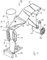
- Fig. 7 shows a vertical pillow type form-fill-seal packaging machine 90 as an example of packaging machines which may incorporate a former according to this invention.
- the flexible thermoplastic bag-making material f (or a film) is originally in the form of a web roll 92 supported around a shaft 95 (serving as web supporting means).
- the film f, pulled out of the web roll 92, is guided by a plurality of guide rolls (including dancer rollers) 105 to the former 10 as described above with reference to Fig. 1.
- the film f After the film f is thereby formed into a tubular shape, by sliding on the shoulder part 30 and changing the direction of its motion at its connecting line 40 with the tubular part 30, it is pulled downward by a film-pulling unit 100 including a pair of pull-down belts 101 which run parallel to each other and a longitudinal sealer in the form of a heater belt 102 for sealing together the mutually overlapping edge portions of the film f.
- the film f which is now in a cylindrical form, is sealed horizontally (that is, transversely to its downward direction of motion) by a transverse sealer 110, as articles to be packaged are dropped from the hopper 15.
- the transverse sealer 110 may be of a design provided with a fixed seal jaw 112 and a mobile seal jaw 114 both of a known structure and disposed below the film-pulling unit 100.
- numeral 113 indicates a blade for cutting the film f transversely between the bags into which the film f has been formed.
- formers according to this invention can be incorporated in many other kinds of packaging machines and bag makers where it is required to bend a longitudinally traveling flexible bag-making material into a tubular form.
Landscapes
- Engineering & Computer Science (AREA)
- Mechanical Engineering (AREA)
- Containers And Plastic Fillers For Packaging (AREA)
- Making Paper Articles (AREA)
Abstract
Description
- This invention relates to a former for a bag maker and a method of producing such a former. This invention also relates to packaging machines incorporating such a former.
- A bag maker-packaging machine, such as a vertical pillow-type form-fill-seal packaging machine as disclosed, for example, in U.S. Patent 5,237,798 issued August 24, 1993, makes use of a component commonly known as a former for bending an elongated flexible bag-making material into a cylindrical form, generally composed of a vertically extending tubular part and a so-called shoulder part (sometimes also called a skirt-like part) having a sloped planar guide section. The bag-making material, say, in the form of a web, is longitudinally transported towards the former horizontally in a flat form, moves over and along this sloped planar guide section of the shoulder part, changes the direction of its motion sharply as it crosses the connecting line at which the tubular and shoulder parts are attached together so as to move inside the tubular part and is pulled downward axially along the inner surface of the tubular part. In other words, the bag-making material is pushed upwards first over the sloped planar guide section of the shoulder part, changes the direction of its motion sharply at the connecting line as it is folded into a tubular form, and then is pulled downward by the force not only of the articles which are dropped in to be packaged in the bag being made but also of a pull-down belt or the like (not shown) for causing the motion of the bag-making material. Thus, it is crucial that the connecting line, at which the bag-making material is forced to change the direction of its motion sharply, be a continuous smooth curve shaped correctly because, if it is not shaped correctly or has even a small unevenness, the material is likely to become wrinkled or develop small longitudinal lines on the surface.
- Formers of this type are usually produced by casting, a master mold being used thereafter to carry out an accurate copy process for shaping the connecting line correctly. This, however, requires a long time of hard work by an experienced worker, adding to the production cost, and fluctuations and non-uniformity in the shape of formers make them non-exchangeable. Moreover, many formers are usually required for producing bags of different sizes. Even when bags of the same size are produced, different formers are generally required, depending upon where and how the side edges of the elongated bag-making material should be overlapped for longitudinal sealing. The angle of the sloped planar guide section of the shoulder part must be changed, furthermore, depending on the physical properties of the bag-making material such as its thickness. In short, the cost of equipping a bag maker with a sufficient number of formers with different kinds is substantial if prior art technology is relied upon.
- In accordance with one aspect of the present invention, a former for forming an elongated planar bag-making material into a tubular form comprises a hollow cylindrical tubular part having an inner surface and defining an axial direction; and a shoulder part which has a planar guide section and is connected to said tubular part along a connecting line which surrounds said tubular part such that said material is transported over said planar guide section of said shoulder part, changes direction of motion sharply at said connecting line into said axial direction and is transformed into a tubular form along said inner surface of said tubular part, the angle between the tangent and said connecting line and a plane perpendicular to said axial direction changing at a constant rate.
- In accordance with a second aspect of the present invention, a method of making a former which is adapted to form an elongated planar bag-making material into a tubular form and comprises a hollow cylindrical tubular part defining an axial direction and a shoulder part having a planar guide section and being connected to said tubular part along a connecting line such that said material is transported over said planar guide section of said shoulder part, changes direction of motion sharply at said connecting line into said axial direction and is transformed into a tubular form along inner surface of said tubular part comprises the steps of: cutting a tube-forming piece and a shoulder-forming piece from a flat blank sheet, each of said pieces having a specified geometrical shape with a specified width between side edges and a curved edge section; bending said tube-forming piece into said tubular form to form said tubular part by bringing the side edges together; bending said shoulder-forming piece to form said shoulder part by forming said planar guide section and to match the curved edge section of said shoulder-forming piece with the curved edge section of said tube-forming piece; and attaching said bent pieces together along said curved edge sections to form said connecting line, said connecting line being shaped such that the angle between the tangent to said connecting line and a plane perpendicular to said axial direction changes at a constant rate.
- This invention provides a method of producing formers of different kinds accurately and automatically.
- This invention also provides formers produced by such a method, having their tubular and shoulder parts formed by bending pieces which are cut from a blank sheet by a numerically controlled cutting machine.
- In one example, a former according to the present invention may be characterized not only as being composed of a hollow cylindrical tubular part defining an axial direction and a shoulder part which has a planar guide section and is attached to the tubular part along a closed three-dimensional line (referred to as the connecting line) such that an elongated bag-making material transported over the sloped planar guide section of the shoulder part can be made into a tubular form as it crosses the connecting line to move into the tubular part, but wherein the aforementioned connecting line between the tubular and shoulder parts is shaped such that the angle between its tangent and a plane perpendicular to the axial direction of the tubular part changes at a constant rate with respect to the change in position of the contact point of the tangent with the connecting line, for example, in the direction perpendicular to the axial direction of the tubular part or along the connecting line itself.
- To produce such a former according to the present invention, pieces to be made into the tubular and shoulder parts are cut out from a blank sheet in specified geometrical shapes, bent and folded appropriately into predetermined shapes of the tubular and shoulder parts, and attached together, say, by welding, along the aforementioned connecting line. The geometrical shapes into which the blank sheet is cut are determined such that, when these pieces are bent, folded and attached together as described above, the connecting line therebetween will satisfy the condition imposed according to this invention as described above regarding the rate of change in its slope.
- Depending upon what kind of seals are desired, side strips of different widths may be provided along the side edges of the pieces to be cut out from the blank sheet.
- The accompanying drawings, which are incorporated in and form a part of this specification, illustrate embodiments of the invention and, together with the description, serve to explain the principles of the invention. In the drawings:
- Fig. 1 is a view of a former according to the present invention as a part of a vertical pillow type bag maker-packaging machine;
- Figs. 2A and 2B are plan views of portions of a blank sheet material cut respectively for forming a shoulder part and a tubular part of a former according to this invention;
- Figs. 3A and 3B are diagonal external views of two tube-forming pieces about to be made into a tubular part of a former;
- Fig. 4 shows a curve representing the curved edge sections of Figs. 2A and 2B;
- Fig. 5 is a projection of the former according to this invention onto the ξζ-plane;
- Figs. 6A, 6B, 6C and 6D are sketches of different ways of making a longitudinal seal to make bags; and
- Fig. 7 is a schematic diagonal view of a portion of a packaging machine of a form-fill-seal type incorporating the former of Fig. 1.
- Fig. 1 shows at 10 an example of formers according to the present invention, comprised essentially, like a prior art former, of a
hopper 15, atubular part 20 and ashoulder part 30 which are attached to each other. The three-dimensionally curved closed line along which thetubular part 20 and theshoulder part 30 will be referred to as a connecting line 40 (and also indicated by letter Q). - To form the
tubular part 20 and theshoulder part 30, a blank sheet material is cut into specified geometrical shapes as shown in Figs. 2A and 2B, bending them and attaching them together. For the purpose of description, the pieces of a blank sheet thus cut out are herein referred to as the tube-formingpiece 52 and the shoulder-makingpiece 53, respectively. - Fig. 3A shows how the tube-forming piece shown in Fig. 2B may be bent into a tubular form to form the
tubular part 20. It is to be noted that both the tube-forming and shoulder-formingpieces curved edge section 54. When the tube-forming and shoulder-formingpieces shoulder parts curved edge sections 54 become the connectingline 40, along which the tubular andshoulder parts line 40, and the problem of how to determine the shape of thecurved edge section 54 when the tube-forming and shoulder-formingpieces - Roughly described, the
tubular part 20 is of the shape of a cylinder which has been cut by a sloped plane, as shown both in Figs. 1 and 3A. For the sake of description, let us assume that thetubular part 20 is standing up vertically, or that it has a vertical axial direction, as shown in Fig. 3A with the highest and lowest points on the connecting line Q indicated by letters O and A, respectively. For convenience, a three-dimensional rectilinear coordinate system with mutually perpendicular ξ, η and ζ-axes is defined, as shown in Fig. 3A, with the origin at O, the ζ-axis extending vertically downward, the lowest point A of the connecting line Q being on the ξζ-plane. The ξη-plane will be also referred to as the horizontal plane, and the projection of the cylindrical form of thetubular part 20 onto the horizontal plane will be referred to as the cross-section curve. Cross-section curves which are symmetric with respect to the ξ-axis, such as a circle, and connecting lines which are symmetric with respect to the ξζ-plane will be considered throughout herein, although this is not intended to limit the scope of the invention. - Fig. 4 shows the shape of the
curved edge section 54, that is, the portion of the tube-formingpiece 52 which, when bent, will form the connecting line Q. In other words, Fig. 4 shows the curve which will be obtained, corresponding to the connecting line Q, if thetubular part 20 shown in Fig. 3A is unbent and flattened. This two-dimensional curve, representing the aforementionedcurved edge sections 54, will be hereinafter referred to as the edge curve, and a two-dimensional rectilinear coordinate system with mutually perpendicular x and z-axes is defined, for convenience as shown in Fig. 4, with the z-axis coinciding with the ζ-axis and the origin O at the same position as shown in Fig. 3A. - Broadly stated, the goal of this invention is to properly design the edge curve such that a bag-making material (as indicated by letter f in Fig. 1) will smoothly change the direction of its motion as it is pulled across the connecting line Q. It therefore goes without saying that the edge curve in Fig. 4 should be a smoothly bending curve. This condition alone, however, is not sufficient to determine the shape of the curve. According to this invention, the connecting line Q is required to change its slope uniformly. Stated more precisely, the angle between the tangent to the connecting line Q and the horizontal plane is required to change at a constant rate.
- According to one embodiment of this invention, the aforementioned constant rate is with respect to the x-coordinate of the contact point at which the connecting line Q and its tangent contact each other. In other words, slope of the tangent of the connecting line Q must change at a constant rate with respect the perpendicular component of change in position of the contact point between the connecting line Q and its tangent with respect to the axial direction of the
tubular part 20. If an arbitrary point on the connecting line Q is denoted by P, the slope as defined above at point P is the tangent of angle γ indicated in Fig. 4. Thus, since


- If the cross-section curve is a circle of radius


- According to another embodiment of this invention, the aforementioned constant rate is along the connecting line Q itself. If the distance of the arbitrary point P from the origin O along the connecting line Q (or the edge curve) is denoted by s, as shown in Fig. 4, this condition translates into:


- The portion of the
shoulder part 30 corresponding to the connecting line Q is shaped identically. It must be so since each part of the bag-making material f must travel the same distance before and after it is transformed into a tubular shape. - As shown in Fig. 1, the
shoulder part 30 has a slopedplanar guide section 33 over which the bag-making material f is caused to slide upward before the direction of its motion is suddenly changed downward when it reaches the connectingline 40. The angle of thisplanar guide section 33 with the horizontal direction is denoted by ρ in Fig. 5. Fig. 5 also shows the projection of the connecting line Q onto the ξζ-plane. - If the cross-section curve is a circle, the angle δ between this sloped
planar guide section 33 of theshoulder part 30 and the projection of the connecting line Q onto the ξζ-plane is given, from (6), by:

planar guide section 33 is set equal to π/4, as a typical example, H = 0.233π2r. Thus, it becomes possible to design standardized formers. - After the longitudinally elongated bag-making material f is bent into a tubular form by the former, its side edges are overlapped and stuck together. As shown in Figs. 6A, 6B, 6C and 6D, however, there are many different ways of carrying out this longitudinal sealing process. Fig. 6A shows a standard fin seal whereby the inner surfaces of both side edges of the material are stuck together and the two side edges are then folded in one direction. Fig. 6B shows a lap seal, which is also sometimes called an envelope seal, whereby the inner surface of one side edge is stuck to the outer surface of the other edge. Depending on which kind of seal is desired, both the positions and the widths of the joined areas must be differently determined. Fig. 6C shows a kind of offset seal whereby the overlapped edges are folded in one direction such that either the fold line or the outer edges will be at the center in the direction of the width of the bag. In this case, too, both the positions and the widths of the areas for making the joint change, depending upon the kind of the seal. Fig. 6D shows still another seal whereby the edges are folded in the reverse direction after a fin seal has been made. When the tube-forming piece is bent to form the tubular part, its side edge parts are either overlapped as shown in Fig. 3A or made to form a
flat part 34 as shown in Fig. 3B such that a pair of mutually opposite vertical sealers (not shown) can be used to form a fin seal. In summary, the width W of the narrow strip for making an overlap, when a blank sheet is cut as shown in Figs. 2A and 2B, should be determined, depending upon what kind of sealing is intended when bags are formed at a later stage after the bag-making material f is bent into a tubular form by the former. - After the width W of the overlap is thus determined and the constants in (3) or (11) are determined for the connecting part, for example, on the basis of the size of the bags to be made, the shape as shown in Figs. 2A and 2B, in which the blank sheet should be cut, is determined. In accordance, a CAD/CAM system may be used to create a numerical control program automatically on the basis of such determinations as well as physical properties of the blank sheet such as its thickness. A numerically controlled laser cutter is operated by such a program to cut a blank sheet as shown in Figs. 2A and 2B in single strokes and obtain pieces to be bent to make the tubular and shoulder parts. These parts are positioned next to each other along their connecting lines and welded together to build a former as shown in Fig. 1.
- The invention was described above with reference to only two examples wherein the constant rate of change in the slope of the connecting line Q was with reference either to the x-axis or along the connecting line Q itself (or with reference to the variable s), but these examples are not intended to limit the scope of the invention. In the case of the illustrated examples, however, the shape of the curved edge section of the tube-forming and shoulder-forming pieces can be written in a closed form in terms of a known function, and this makes it easier to produce the numerical control program accurately for the means such as a laser cutter for cutting a blank sheet to obtain the tube-forming and shoulder-forming pieces.
- As for the cross-sectional shape of the tubular part, it is not required to be circular. For making relatively large bags, for example, a somewhat elongated circular shape may be preferred such as a shape comprised of two semi-circles connected with two straight side lines or an elliptical cross-sectional shape. Since the condition imposed upon the shape of the connecting line according to this invention does not depend upon the cross-sectional shape of the tubular part, the present invention, as described above, is applicable to tubular parts with different cross-sectional shapes.
- Fig. 7 shows a vertical pillow type form-fill-
seal packaging machine 90 as an example of packaging machines which may incorporate a former according to this invention. The flexible thermoplastic bag-making material f (or a film) is originally in the form of aweb roll 92 supported around a shaft 95 (serving as web supporting means). The film f, pulled out of theweb roll 92, is guided by a plurality of guide rolls (including dancer rollers) 105 to the former 10 as described above with reference to Fig. 1. After the film f is thereby formed into a tubular shape, by sliding on theshoulder part 30 and changing the direction of its motion at its connectingline 40 with thetubular part 30, it is pulled downward by a film-pullingunit 100 including a pair of pull-downbelts 101 which run parallel to each other and a longitudinal sealer in the form of aheater belt 102 for sealing together the mutually overlapping edge portions of the film f. The film f, which is now in a cylindrical form, is sealed horizontally (that is, transversely to its downward direction of motion) by atransverse sealer 110, as articles to be packaged are dropped from thehopper 15. Thetransverse sealer 110 may be of a design provided with a fixedseal jaw 112 and a mobile seal jaw 114 both of a known structure and disposed below the film-pullingunit 100. In Fig. 7, numeral 113 indicates a blade for cutting the film f transversely between the bags into which the film f has been formed. - It is to be noted that formers according to this invention can be incorporated in many other kinds of packaging machines and bag makers where it is required to bend a longitudinally traveling flexible bag-making material into a tubular form.
Claims (16)
- A former for forming an elongated planar bag-making material into a tubular form, said former comprising:a hollow cylindrical tubular part having an inner surface and defining an axial direction; anda shoulder part which has a planar guide section and is connected to said tubular part along a connecting line which surrounds said tubular part such that said material is transported over said planar guide section of said shoulder part, changes direction of motion sharply at said connecting line into said axial direction and is transformed into a tubular form along said inner surface of said tubular part, the angle between the tangent to said connecting line and a plane perpendicular to said axial direction changing at a constant rate.
- The former of claim 1 wherein said constant rate is with respect to the perpendicular component of change in position of the contact point between said connecting line and said tangent with respect to said axial direction.
- The former of claim 1 wherein said constant rate is with respect to the change in position of the contact point between said connecting line and said tangent along said connecting line.
- The former of claim 1 wherein said connecting line becomes a parabola if said tubular part is cut along a line parallel to said axial direction and is flattened.
- The former of claim 1 wherein said connecting line becomes a hyperbolic function curve if said tubular part is cut along a line parallel to said axial direction and is flattened.
- The former of claim 4 wherein the shape of said parabola is determined in part by a specified difference in height between the highest and lowest points on said connecting line measured along said axial direction.
- The former of claim 5 wherein the shape of said hyperbolic sine curve is determined in part by a specified difference in height between the highest and lowest points on said connecting line measured along said axial direction.
- A method of making a former which is adapted to form an elongated planar bag-making material into a tubular form and comprises a hollow cylindrical tubular part defining an axial direction and a shoulder part having a planar guide section and being connected to said tubular part along a connecting line such that said material is transported over said planar guide section of said shoulder part, changes direction of motion sharply at said connecting line into said axial direction and is transformed into a tubular form along inner surface of said tubular part, said method comprising the steps of:cutting a tube-forming piece and a shoulder-forming piece from a flat blank sheet, each of said pieces having a specified geometrical shape with a specified width between side edges and a curved edge section;bending said tube-forming piece into said tubular form to form said tubular part by bringing the side edges together;bending said shoulder-forming piece to form said shoulder part by forming said planar guide section and to match the curved edge section of said shoulder-forming piece with the curved edge section of said tube-forming piece; andattaching said bent pieces together along said curved edge sections to form said connecting line, said connecting line being shaped such that the angle between the tangent to said connecting line and a plane perpendicular to said axial direction changes at a constant rate.
- The method of claim 8 wherein said constant rate is with respect to the perpendicular component of change in position of the contact point between said connecting line and said tangent with respect to said axial direction.
- The method of claim 8 wherein said constant rate is with respect to the change in position of the contact point between said connecting line and said tangent along said connecting line.
- The method of claim 8 wherein said curved edge sections are a parabola.
- The method of claim 8 wherein said curved edge sections are a hyperbolic function curve.
- The method of claim 11 further comprising the step of determining the shape of said parabola in part by specifying a difference in height between the highest and lowest points on said connecting line measured along said axial direction.
- The method of claim 12 further comprising the step of determining the shape of said hyperbolic function curve in part by specifying a difference in height between the highest and lowest points on said connecting line measured along said axial direction.
- The method of claim 8 wherein said cutting step comprises obtaining a numerical control program based on the shape of said curved edge section and operating a laser cutter by said numerical control program.
- A packaging machine comprising:a web supporting means supporting a web roll having a web of a bag-making material wound around a core shaft;a former according to any of claims 1 to 7 or manufactured in accordance with any of claims 9 to 15;web guiding means for guiding said web from said web roll to said former and said tubularly formed web in a longitudinal direction;a longitudinal sealer for sealing side edges of said tubularly formed web together in said longitudinal direction; anda traverse sealer having a pair of sealing means for compressing and sealing sheets of said tubularly formed web together therebetween transversely to said longitudinal direction and thereby forming a bag.
Priority Applications (2)
| Application Number | Priority Date | Filing Date | Title |
|---|---|---|---|
| DE1995610204 DE69510204T2 (en) | 1995-11-23 | 1995-11-23 | Shaped shoulder for a device for manufacturing bags and method for the production thereof. |
| EP19950308427 EP0775634B1 (en) | 1995-11-23 | 1995-11-23 | Former for a bag maker and method of producing same |
Applications Claiming Priority (1)
| Application Number | Priority Date | Filing Date | Title |
|---|---|---|---|
| EP19950308427 EP0775634B1 (en) | 1995-11-23 | 1995-11-23 | Former for a bag maker and method of producing same |
Publications (2)
| Publication Number | Publication Date |
|---|---|
| EP0775634A1 true EP0775634A1 (en) | 1997-05-28 |
| EP0775634B1 EP0775634B1 (en) | 1999-06-09 |
Family
ID=8221411
Family Applications (1)
| Application Number | Title | Priority Date | Filing Date |
|---|---|---|---|
| EP19950308427 Expired - Lifetime EP0775634B1 (en) | 1995-11-23 | 1995-11-23 | Former for a bag maker and method of producing same |
Country Status (2)
| Country | Link |
|---|---|
| EP (1) | EP0775634B1 (en) |
| DE (1) | DE69510204T2 (en) |
Cited By (3)
| Publication number | Priority date | Publication date | Assignee | Title |
|---|---|---|---|---|
| US7214173B2 (en) * | 2000-10-30 | 2007-05-08 | Pactiv Corporation | Laser for forming bags from a web of material |
| CN110683139A (en) * | 2019-10-11 | 2020-01-14 | 广州三木汽车部件有限公司 | Automobile interior part packaging machine |
| JP2020023361A (en) * | 2013-11-19 | 2020-02-13 | ティエヌエイ オーストラリア ピーティワイ リミテッド | Film drive assembly, former shoulder, and combined body of former shoulder baseplate |
Families Citing this family (1)
| Publication number | Priority date | Publication date | Assignee | Title |
|---|---|---|---|---|
| US7367931B2 (en) | 2000-10-30 | 2008-05-06 | Pactiv Corporation | Laser cutoff stacker assembly |
Citations (6)
| Publication number | Priority date | Publication date | Assignee | Title |
|---|---|---|---|---|
| GB913114A (en) * | 1959-07-27 | 1962-12-19 | William Clair Leasure | Packaging methods and apparatus |
| US3494265A (en) * | 1968-02-01 | 1970-02-10 | Woodman Co | Package former with multiple elliptical curve |
| US3636826A (en) * | 1969-10-24 | 1972-01-25 | Burlie R Bowen | Folding shoe for use in a packaging machine |
| US4918611A (en) * | 1988-07-21 | 1990-04-17 | Industrial Technology Research Institute | Method and apparatus for controlling laser cutting by image processing |
| DE4038888A1 (en) * | 1990-12-06 | 1992-06-11 | Rovema Gmbh | Plastics bag shaping shoulder production method - mills from cast blank to produce free-forming surfaces |
| US5237798A (en) | 1991-07-12 | 1993-08-24 | Ishida Scales Mfg. Co., Ltd. | Packaging machine with improved film-transporting device |
-
1995
- 1995-11-23 EP EP19950308427 patent/EP0775634B1/en not_active Expired - Lifetime
- 1995-11-23 DE DE1995610204 patent/DE69510204T2/en not_active Expired - Fee Related
Patent Citations (6)
| Publication number | Priority date | Publication date | Assignee | Title |
|---|---|---|---|---|
| GB913114A (en) * | 1959-07-27 | 1962-12-19 | William Clair Leasure | Packaging methods and apparatus |
| US3494265A (en) * | 1968-02-01 | 1970-02-10 | Woodman Co | Package former with multiple elliptical curve |
| US3636826A (en) * | 1969-10-24 | 1972-01-25 | Burlie R Bowen | Folding shoe for use in a packaging machine |
| US4918611A (en) * | 1988-07-21 | 1990-04-17 | Industrial Technology Research Institute | Method and apparatus for controlling laser cutting by image processing |
| DE4038888A1 (en) * | 1990-12-06 | 1992-06-11 | Rovema Gmbh | Plastics bag shaping shoulder production method - mills from cast blank to produce free-forming surfaces |
| US5237798A (en) | 1991-07-12 | 1993-08-24 | Ishida Scales Mfg. Co., Ltd. | Packaging machine with improved film-transporting device |
Cited By (3)
| Publication number | Priority date | Publication date | Assignee | Title |
|---|---|---|---|---|
| US7214173B2 (en) * | 2000-10-30 | 2007-05-08 | Pactiv Corporation | Laser for forming bags from a web of material |
| JP2020023361A (en) * | 2013-11-19 | 2020-02-13 | ティエヌエイ オーストラリア ピーティワイ リミテッド | Film drive assembly, former shoulder, and combined body of former shoulder baseplate |
| CN110683139A (en) * | 2019-10-11 | 2020-01-14 | 广州三木汽车部件有限公司 | Automobile interior part packaging machine |
Also Published As
| Publication number | Publication date |
|---|---|
| EP0775634B1 (en) | 1999-06-09 |
| DE69510204T2 (en) | 1999-11-11 |
| DE69510204D1 (en) | 1999-07-15 |
Similar Documents
| Publication | Publication Date | Title |
|---|---|---|
| US6428457B1 (en) | Former for a bag maker | |
| US7556595B2 (en) | Method and device for the production of packaging in bags | |
| US6925779B2 (en) | Method and apparatus for placing a product in a flexible recloseable container | |
| EP0460540B1 (en) | A forming device in packaging machines | |
| US8616768B2 (en) | Pleated stand-up packaging pouch, pleated stand-up packaging body, feed roll for pleated stand-up packaging body, and method of manufacturing pleated stand-up packaging body | |
| US6675552B2 (en) | Method and device for producing bags with three sealed edges and welded-in closing seal | |
| US3980225A (en) | Self-standing bag | |
| US9061783B2 (en) | Fin seal registration in manufacture of reclosable packages | |
| EP0775634B1 (en) | Former for a bag maker and method of producing same | |
| CN111788067B (en) | Bag making machine and method for manufacturing plastic bag | |
| CA3098804C (en) | Method and machine for making flexible packages with side gussets | |
| JP5174426B2 (en) | Self-supporting packaging bag with folds, self-supporting package with folds, raw roll for fold-free self-supporting package, and method for producing self-supporting package with folds | |
| US3417674A (en) | Method and apparatus for forming parallelepipedic packages having folded-up end flaps from a continuous tubular material and for effecting a two-stage advance of the material to ensure proper registration for indicia on the package | |
| JP2006501081A (en) | Molding system for containers, especially food containers | |
| EP3164262B1 (en) | Folding arrangement, folding machine comprising said folding arrangement and method for folding using said folding arrangement | |
| JP7180930B2 (en) | Heat sealing device and bag making machine | |
| EP3013163B2 (en) | Device for welding a zip seal in a tobacco pouch | |
| EP2497716A1 (en) | Vertical flow wrapper with film feed means | |
| EP2154094A1 (en) | A method and an apparatus for forming an edge thickening along a web material and a web material thus formed | |
| JPH07315313A (en) | Former used for packing machine and production thereof | |
| JP2000118513A (en) | Method and device for forming package | |
| JPH08324505A (en) | Former used in packaging machine and manufacture thereof | |
| JPH01310946A (en) | Apparatus for preparing envelope lined with buffer material | |
| JPS6259646B2 (en) | ||
| ITUB20153741A1 (en) | DEVICE AND PROCEDURE FOR MANUFACTURING BAG PACKAGES |
Legal Events
| Date | Code | Title | Description |
|---|---|---|---|
| PUAI | Public reference made under article 153(3) epc to a published international application that has entered the european phase |
Free format text: ORIGINAL CODE: 0009012 |
|
| AK | Designated contracting states |
Kind code of ref document: A1 Designated state(s): DE FR GB IT |
|
| 17P | Request for examination filed |
Effective date: 19971120 |
|
| 17Q | First examination report despatched |
Effective date: 19980119 |
|
| GRAG | Despatch of communication of intention to grant |
Free format text: ORIGINAL CODE: EPIDOS AGRA |
|
| GRAG | Despatch of communication of intention to grant |
Free format text: ORIGINAL CODE: EPIDOS AGRA |
|
| GRAH | Despatch of communication of intention to grant a patent |
Free format text: ORIGINAL CODE: EPIDOS IGRA |
|
| GRAH | Despatch of communication of intention to grant a patent |
Free format text: ORIGINAL CODE: EPIDOS IGRA |
|
| GRAA | (expected) grant |
Free format text: ORIGINAL CODE: 0009210 |
|
| AK | Designated contracting states |
Kind code of ref document: B1 Designated state(s): DE FR GB IT |
|
| ET | Fr: translation filed | ||
| REF | Corresponds to: |
Ref document number: 69510204 Country of ref document: DE Date of ref document: 19990715 |
|
| ITF | It: translation for a ep patent filed | ||
| PLBE | No opposition filed within time limit |
Free format text: ORIGINAL CODE: 0009261 |
|
| STAA | Information on the status of an ep patent application or granted ep patent |
Free format text: STATUS: NO OPPOSITION FILED WITHIN TIME LIMIT |
|
| 26N | No opposition filed | ||
| REG | Reference to a national code |
Ref country code: GB Ref legal event code: IF02 |
|
| PGFP | Annual fee paid to national office [announced via postgrant information from national office to epo] |
Ref country code: FR Payment date: 20031110 Year of fee payment: 9 |
|
| PGFP | Annual fee paid to national office [announced via postgrant information from national office to epo] |
Ref country code: GB Payment date: 20031119 Year of fee payment: 9 |
|
| PGFP | Annual fee paid to national office [announced via postgrant information from national office to epo] |
Ref country code: DE Payment date: 20031204 Year of fee payment: 9 |
|
| PG25 | Lapsed in a contracting state [announced via postgrant information from national office to epo] |
Ref country code: GB Free format text: LAPSE BECAUSE OF NON-PAYMENT OF DUE FEES Effective date: 20041123 |
|
| PG25 | Lapsed in a contracting state [announced via postgrant information from national office to epo] |
Ref country code: DE Free format text: LAPSE BECAUSE OF NON-PAYMENT OF DUE FEES Effective date: 20050601 |
|
| GBPC | Gb: european patent ceased through non-payment of renewal fee |
Effective date: 20041123 |
|
| PG25 | Lapsed in a contracting state [announced via postgrant information from national office to epo] |
Ref country code: FR Free format text: LAPSE BECAUSE OF NON-PAYMENT OF DUE FEES Effective date: 20050729 |
|
| REG | Reference to a national code |
Ref country code: FR Ref legal event code: ST |
|
| PG25 | Lapsed in a contracting state [announced via postgrant information from national office to epo] |
Ref country code: IT Free format text: LAPSE BECAUSE OF NON-PAYMENT OF DUE FEES;WARNING: LAPSES OF ITALIAN PATENTS WITH EFFECTIVE DATE BEFORE 2007 MAY HAVE OCCURRED AT ANY TIME BEFORE 2007. THE CORRECT EFFECTIVE DATE MAY BE DIFFERENT FROM THE ONE RECORDED. Effective date: 20051123 |