EP0775396B1 - Uberwachung von ubertragungsnetzen im betrieb - Google Patents
Uberwachung von ubertragungsnetzen im betrieb Download PDFInfo
- Publication number
- EP0775396B1 EP0775396B1 EP95927851A EP95927851A EP0775396B1 EP 0775396 B1 EP0775396 B1 EP 0775396B1 EP 95927851 A EP95927851 A EP 95927851A EP 95927851 A EP95927851 A EP 95927851A EP 0775396 B1 EP0775396 B1 EP 0775396B1
- Authority
- EP
- European Patent Office
- Prior art keywords
- path
- scrambler
- alarm indication
- communications
- indication signal
- Prior art date
- Legal status (The legal status is an assumption and is not a legal conclusion. Google has not performed a legal analysis and makes no representation as to the accuracy of the status listed.)
- Expired - Lifetime
Links
Images


Classifications
-
- H—ELECTRICITY
- H04—ELECTRIC COMMUNICATION TECHNIQUE
- H04L—TRANSMISSION OF DIGITAL INFORMATION, e.g. TELEGRAPHIC COMMUNICATION
- H04L1/00—Arrangements for detecting or preventing errors in the information received
- H04L1/0078—Avoidance of errors by organising the transmitted data in a format specifically designed to deal with errors, e.g. location
- H04L1/0083—Formatting with frames or packets; Protocol or part of protocol for error control
-
- H—ELECTRICITY
- H04—ELECTRIC COMMUNICATION TECHNIQUE
- H04J—MULTIPLEX COMMUNICATION
- H04J3/00—Time-division multiplex systems
- H04J3/02—Details
- H04J3/14—Monitoring arrangements
Definitions
- the present invention relates to means for monitoring communications networks, in particular arrangements for detecting faults affecting traffic signal paths.
- the alarm may indicate what kind of failure has occurred.
- AIS Alarm Indication Signal
- Digital communications systems used by network operators have an established practice in which a loss of signal detected by a piece of equipment downstream from a fault in a path causes the equipment to send an AIS.
- This is normally in the form of a continuous stream of digital "1"s.
- the AIS could be in any other form defined and recognised by the network in question, but digital "1"s have been found particularly appropriate.
- the AIS must be detectable and generally AIS detection criteria are set at a threshold of a given number of continuous digital "1"s, or a given density of "1"s over a certain span of bits.
- the AIS may be set at a relatively high level so that detection is not assumed after only a short string of "1"s. Because network performance is important to both customer and network operator, both the time and the number of incidents for which an AIS is triggered may be recorded.
- a deterministic frame structure is one in which a source sends a signal with a well defined structure at the binary level in the form of overhead plus payload.
- a deterministic frame structure is one in which a source sends a signal with a well defined structure at the binary level in the form of overhead plus payload.
- 'Structured' services usually take the form of a standardised path overhead (such as a periodic framing pattern perhaps with a CRC-type function which can be used for monitoring purposes) and a well defined payload area for the, usually non-deterministic, customer traffic signal.
- a structured signal is the G.704/G.706 ITU recommended frame structure for the 2048kbit/s network layer path signal.
- the path overhead is defined in Timeslot 0 (which contains, amongst other functions, both a frame alignment signal and a CRC), and the payload the customer can use is, in most cases, the remaining 31 Timeslots of the frame in some format (thus giving the customer a maximum aggregate 1984kbit/s payload channel).
- a particular problem with unstructured services is thus that the network operator might not be quickly (if at all) aware of path failures. In some cases this information is first provided by the customer.
- AIS Alarm Indication Signal
- DE-A-2,647,716 discloses a system in which a particular frame word is provided for the purpose of fault detection.
- EP-A-0,306,585 discloses a suitable alarm indication signal format that could be used in the arrangement shown in DE-A-2,647,716.
- neither of these references address the problems concerned with such fault detection in unstructured services i.e. when the signals have no generic frame structure.
- a communications system for transmitting communications signals on a communications path in the provision of unstructured services, the communications path comprising one or more elements capable of outputting an alarm indication signal for transmission on the path in response to a fault condition arising, said communications system comprising a scrambler for scrambling communications signals input to the path for transmission thereon, and a descrambler to descramble the transmitted, scrambled communications signals, said one or more elements lying between the scrambler and the descrambler, and wherein an alarm indication signal detector is provided between the scrambler and the descrambler for detecting alarm indication signals carried by the path.
- the alarm indication signal may, for instance, comprise a series of repeated bits, such as all "1"s, in a digital communications system.
- Embodiments of the present invention can then provide communication paths dedicated to the use of a specific customer wherein the customer's signal is scrambled at the input to the communications path and unscrambled before being received by the customer's equipment at the end of the path.
- This allows the customer ostensibly to use an all "1"s signal for his own purposes, such a signal in practice being scrambled while carried by the path and therefore not detectable as an AIS by the AIS detector at the receiving end of the path.
- a method of monitoring a communications path for faults occurring which affect traffic on the path including the steps of scrambling traffic signals to be transmitted on the path, transmitting said scrambled traffic signals along the path, monitoring the path for an AIS, and unscrambling the traffic signals by means of an unscrambling device.
- Embodiments of the invention can detect in particular an AIS occurring on the path between a point where the traffic signals are scrambled and where they are unscrambled.
- a network terminating unit (3,8) for use with a communications path (5,6,7) in a network in the provision of unstructured services, at least one element of the path (5,6,7) having means to output an alarm indication signal on the path in the event of a fault occurring upstream with respect to it in the path, wherein the network terminating unit (3,8) has descrambling means D,10) for descrambling scrambled traffic signals received from the path (5,6,7), and alarm indication signal detecting means (M,9) for detecting an alarm indication signal transmitted on the path (5,6,7), the alarm indication signal detecting means (M,9) being arranged in the network terminating unit (3,8) to receive the scrambled traffic signals from the path (5,6,7), or an alarm indication signal in the event that an alarm indication signal is transmitted on the path (5,6,7).
- the network terminating unit (3,8) has descrambling means D,10) for descrambling scrambled traffic signals received from the path (5,6,7), and alarm indication signal detecting means (M,9) for
- a customer's data may be scrambled as it transits a first NTU (Network Terminating Unit), at a first end of the path, and descrambled as it transits a second NTU at a second end of the path.
- NTU Network Terminating Unit
- Each NTU may be used to connect individual customer terminals, for instance data terminals, to a telecommunications network.
- n x 64kbit/sec, 2048kbit/sec, 8448 kbit/sec and 34368kbit/sec and provided as a standard service do not have a deterministic frame structure comprising payload and overhead.
- Embodiments of this invention could be used to provide performance monitoring functions for these paths.
- a first is the 'hard' failure, where a true loss of a signal (at some network layer) occurs and for which AIS will persist in all downstream client layers until either automatic or manual restoration is effected; and a second is the 'soft' failure, where a transient but gross disturbance of a network layer signal occurs and that network layer loses path alignment.
- a second is the 'soft' failure, where a transient but gross disturbance of a network layer signal occurs and that network layer loses path alignment.
- both the affected network path layer and all client path layers go through a complex loss and recovery of frame alignment until normal operation is resumed.
- the key point to note here is that the network self-recovers without any form of intervention.
- the first type of failure is rather obvious and its implications are easily understood.
- the second type of failure is, however, more interesting and its implications need to be clearly understood to optimise the solution.
- the soft failure is usually a consequence of short but intense error bursts in networks (for example, as small as 10 ms at 140Mbit/s).
- a key facet of this effect is that each client layer loses and recovers frame alignment due to corruption of the justification process, which either inserts an extra bit or deletes a traffic bit from the client layer signal. This effect is known as an 'uncontrolled bit-slip'.
- Unavailability One of the most important parameters to measure from the perspective of both the network operator and the customer is Unavailability.
- the customer and network operator might also have contractual performance agreements on 'Service Availability', such that it is highly desirable that such a measurement can be performed accurately in-service.
- a path is usually defined to enter the Unavailable state (from the Available state) at the onset of a period of several consecutive Severely Errored Seconds (SES).
- SES Severely Errored Seconds
- G.821 and G.826 this is currently defined to be 10 consecutive SES.
- Exit of the Unavailable state (to the Available state) is usually defined at the onset of a period of several consecutive non-SES.
- this is currently defined to be 10 consecutive non-SES.
- a SB is defined in this patent as a number of consecutive SES which terminate before the threshold which defines the onset of Unavailability.
- a SB event terminates on the first non-SES.
- a SB could be defined as a period of between say 3 and 9 consecutive SES.
- such events could be measured as a single class, or they could be sub-divided into several class intervals, with the frequency of SB events in each class interval measured.
- the availability and error performance is to be recorded, a method of measuring it needs to be devised. Since the key measurements are Unavailability and Short Breaks, and since both are based upon the SES, this measure could be the occurrence of the SES. That is, from the above it is clear that the SES (also defined in the above named ITU Recommendations) is the key primary parameter to measure.
- Performance information can either be reported immediately to a network management centre as it occurs, or stored at the NTU where it is measured and then reported once say, every 24 hours, either in response to a polled request or by means of a known autodialling system. Whether immediate or deferred reporting is required will depend upon the nature of the impairment and the maintenance philosophy of the network operator. For example, it could be decided that all unavailability events are always immediately reported (and perhaps stored), whilst occasional SES events are generally stored and only reported in response to polling from a network management system.
- a network terminating unit for use in a communications path, having means for receiving an incoming digital traffic signal, scrambler means for scrambling the traffic signal, and transmission means for transmitting the scrambled signal along a path.
- a second NTU might then be provided at the far end of the path, to receive the scrambled signal.
- the second NTU will then be provided with a descrambler.
- any scrambler/descrambler used will affect network performance. If there is a disturbance at some point then the greater the number of stages in the scrambler the greater the time taken for the disturbance to filter through the descrambler and the greater the time to settle back to normal operation after the disturbance. There are therefore distinct advantages in using a scrambler with a small number of stages.
- Using a scrambler with a small number of stages does lead to the risk that incoming data for a particular state of the scrambler could generate a sequence of digital "1"s of greater length than the threshold length n which is set to detect an AIS. In such circumstances the detection of the AIS would be false.
- an Adverse State Detector which can be used to move the scrambler to a different state.
- the Adverse State Detection system checks the scrambled traffic signal transmitted into the network by the first NTU. If a persistent stream of digital "1"s is detected then the adverse state detector invokes a change of state of the scrambler.
- Figure 1 shows a simple network in which the signal flow is described from left to right. (Similar considerations apply to signals flowing in the reverse direction).
- a piece of Customer Premises Equipment (CPE) 1 is connected via a path 2 to a first NTU 3.
- the NTU 3 provides connection to an allocated path of a serving network 6, over which signals can be carried to a second NTU 8 and delivered to different CPE 12 over path 11.
- CPE Customer Premises Equipment
- an AIS might be generated by a number of different types of fault affecting the path in the serving network 6.
- An AIS can usually be generated by any equipment in a network in response to an immediately upstream fault. This includes for instance multiplexers or elements of line systems such as regenerators or repeaters.
- An AIS arising in the allocated path of the serving network 6 will be carried to the second NTU 8 and it is there that it needs to be distinguishable from ordinary traffic carried by the serving network to that NTU 8.
- the customer traffic signals are scrambled at the transmitting NTU 3 before being input to the path 5.
- everything carried by the path 5 of the serving network 6 goes to an AIS detector and measurement unit 9 in the second NTU 8.
- the detector and measurement unit 9 detects the incoming signals and if an AIS, for instance a continuous sequence of digital "1"s, is detected for longer than a predetermined period, an AIS is deemed to have been detected. Additionally, any one second time period which has an AIS condition present in it is deemed to be an SES.
- the second NTU 8 is also provided with a descrambler 10. If no AIS is detected (i.e. for instance if there is not a continuous sequence of "1"s which exceed a preset threshold n) then the signal is passed to the descrambler 10 where it is descrambled before passing out of the second NTU 8, along the connection 11 to the second CPE 12. A similar process occurs for the signals transmitted in the other direction, i.e. from right to left in the Figure.
- the two NTUs 3, 8 may be interchangeable, both having a scrambler and a descrambler in their transmitting and receiving sections respectively.
- This embodiment enables a customer to use the full bandwidth of the path with a performance monitoring function being provided but without the extra expense of providing additional bandwidth for the performance monitoring.
- Reporting performance data and/or specific events to the Network Management System (NMS) 14 may be, for example, by a dial-up PSTN link (public switched telephone network), by dial up ISDN (Integrated Services Digital Network) or by X25. Once the reports have been received by the NMS 14 then appropriate action can be taken.
- PSTN link public switched telephone network
- ISDN Integrated Services Digital Network
- the customer can generate any binary sequence of '1s' and '0s' usually without restriction.
- the customer signal can be prevented from generating a sequence of greater than say n consecutive binary '1s' into the serving network 6 (i.e. from transmitting NTU 3), and n is chosen optimally in respect of the foregoing discussion, then if a sequence of greater than n consecutive binary all '1s' is detected at the receiving NTU 8 this can be attributed as sourced from within the serving network infrastructure 6 (i.e. a true AIS signal) and can be associated with a SES event occurring.
- the probability of the scrambler generating a consecutive sequence of binary '1s' is a function of both the input customer signal sequence and the state of the scrambler at any point in time. This probability can, perhaps, be made arbitrarily small by using a scrambler (and descrambler) with many stages. However, as indicated above, a large number of stages in the (self-synchronising) scrambler/descrambler equates with a proportionately increased delay in regaining scrambler/ descrambler synchronisation (say due to error events) and there could be increased cost implications. Moreover, the probability of the scrambler not generating a sequence of greater than say n binary '1s' cannot be reduced to zero in any case.
- One method of ensuring that the scrambler cannot generate a consecutive sequence of greater than n binary '1s' is to use an adverse state detector mechanism within the design of the scrambler 4.
- This mechanism checks the binary sequence sent into the network 5, 6, 7 from the NTU 3, and if it detects a persistent stream of all '1s' the mechanism invokes a change of state of the scrambler 4.
- a similar system can be used at the descrambler 10 to correct for this aberration (though this can be omitted on cost grounds if required - the implications of doing this are covered later).
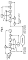
- Figure 2 is an example of a suitable scrambler.
- the example adverse state detector shown consists of an AND gate 20, which logically summates the outputs from the three delay stages x, x 2 and x 3 of the scrambler/descrambler.
- the AND gate is assumed to be at logic state 1 when all three delay stages are at logic state 1.
- a summation device ⁇ counts the number of clock cycles that the outputs of the three delay stages stay at logic state 1.
- An exclusive OR gate shown between delay stages x 3 and x 4 , has the function of inverting the value of the delay stage x 4 . So if during operation of the scrambler all four delay stages are set at 1, and the customer data input signal is also 1, then the output signal to the network will also be 1. This prevails for so long as the customer signal remains at 1.
- the summation device will then count the number of clock cycles that delay stages x, x 2 and x 3 remain at 1. Whilst this remains below a preset threshold the output logic state of the summation device remains at 0. Once the threshold is reached the summation device output is set to logic state 1 which, on the next clock cycle, sets the value in delay stage x 4 to 0. The action of reaching threshold causes the summation device to reset its count and output stages. With complimentary adverse state mechanisms at both scrambler and descrambler, the aberration is corrected at the descrambler. An example of this scrambler and the particular sequence of operation is given in Figure 3.
- a structured network layer path signal When a structured network layer path signal loses frame alignment (or experiences a loss of signal) it generates an AIS downstream as described previously. Since the adverse state detector in the NTU prevents the scrambler from generating a consecutive sequence of more than n (say) binary '1s', then a sequence of greater than n binary '1s' detected at the receiving NTU can be deduced to originate from within the network and hence can be associated with a SES event. The next step, therefore, is to determine a method for setting the value of n at the various network layers at which unstructured services might be offered by network operators.
- a scrambler of m stages cannot generate a consecutive sequence of '1s' greater than 2 m-1 -1 when running through its maximal cycle for a constant input of "0"s or "1"s. If, in the example embodiment of an adverse state mechanism given, the summation device threshold is greater than 2 m-1 -1, but less than a larger value n say, then any sequence of greater than n binary all '1s' can be associated with an AIS (and hence SES) event from within the serving network infrastructure.
- AIS and hence SES
- the threshold of the adverse state detector mechanism should be set greater than 7.
- the adverse state detector threshold was set at 10
- any sequence of greater than 10 consecutive binary '1s' detected at the receiving NTU would be considered to be an AIS (and hence SES) event from within the serving network infrastructure.
- the value of the threshold at which the adverse state detector operates and the threshold at which an AIS (and hence SES) event is detected at the receiving NTU should both be made independently programmable.
- the independently programmable range for each threshold type could be different.
- a SES is deemed to have occurred on an unstructured path when n or more consecutive binary 1s are detected in any 1-second period, where n is programmable over the range 10 to 100 (say) in unit steps.
- the threshold at which the adverse state detection mechanism operates at the scrambler 4 and the descrambler 10 could be defined as follows:
- the adverse state detection mechanism of the scrambler operates when a consecutive sequence of R binary '1s' is detected going into the network from the transmitting NTU, where R is programmable over the range 2 m-1 to n (say); where m is the number of stages in the scrambler and n is the independently programmable threshold set for the detection of a SES event at the receiving NTU.
- the adverse state detection mechanism of the descrambler operates when a consecutive sequence of R binary '1s' is detected coming into the receiving NTU from the network.
- R is programmable over the range 2 m-1 to n (say). Where m is the number of stages in the descrambler and n is the independently programmable threshold set for the detection of a SES event at the receiving NTU.
- the adverse state detection threshold set in the transmitting NTU scrambler and in the receiving NTU descrambler should be the same.
- a mechanism has been described which resides before the descrambler in the receiving NTU 8 and whose function is to detect SES and AIS.
- the descrambler will, with period 2 m-1 , insert a '0' into the output signal transmitted towards the second receiving end of the path 11 to the CPE 12, i.e. there will be a sequence of 2 m-1 -1 consecutive '1s'followed by a '0', and this pattern will repeat as long as the AIS persists into the descrambler.
- the obvious merit of the first option is its simplicity and potential cost saving in the equipment and its operation - though in practice this might be trivial.
- the merit of the other two options is retention of the adverse state detector for correction of customer generated sequences of all '1s'.
Landscapes
- Engineering & Computer Science (AREA)
- Computer Networks & Wireless Communication (AREA)
- Signal Processing (AREA)
- Data Exchanges In Wide-Area Networks (AREA)
- Maintenance And Management Of Digital Transmission (AREA)
- Liquid Developers In Electrophotography (AREA)
- Detection And Prevention Of Errors In Transmission (AREA)
- Synchronisation In Digital Transmission Systems (AREA)
- Time-Division Multiplex Systems (AREA)
Claims (29)
- Kommunikationssystem zum Übertragen von Kommunikationssignalen auf einem Kommunikationsweg (5, 6, 7) bei der Bereitstellung nicht strukturierter Dienste, wobei der Kommunikationsweg (5, 6, 7) ein oder mehrere Elemente (6) enthält, die ein Alarmhinweissignal für die Übertragung auf dem Weg als Antwort auf einen entstehenden Fehlerzustand ausgeben können, wobei das Kommunikationssystem einen Verwürfler (4), der Kommunikationssignale, die auf den Weg (5, 6, 7) ausgegeben werden, um darauf übertragen zu werden, verwürfelt, sowie einen Entwürfler (10), der die übertragenen, verwürfelten Kommunikationssignale entwürfelt, umfaßt, wobei das eine oder die mehreren Elemente (6) zwischen dem Verwürfler (4) und dem Entwürfler (10) liegen,
und wobei zwischen dem Verwürfler (4) und dem Entwürfler (10) ein Alarmhinweissignal-Detektor (9) vorgesehen ist, um vom Weg (5, 6, 7) transportierte Alarmhinweissignale zu erfassen. - Kommunikationssystem nach Anspruch 1, wobei der Verwürfler (4) mit einem Detektor für ungünstige Zustände versehen ist, der ein Kommunikationssignal erfaßt, das, wenn es vom Verwürfler (4) verwürfelt ist, vom Alarmhinweissignal-Detektor (9) als ein Alarmhinweissignal erfaßt würde, wobei der Verwürfler (4) ferner mit einer Einrichtung versehen ist, die sein Ausgangssignal als Antwort auf ein Ausgangssignal vom Detektor für ungünstige Zustände modifiziert, um zu vermeiden, daß das verwürfelte Kommunikationssignal vom Alarmhinweissignal-Detektor (9) als ein Alarmhinweissignal erfaßt wird.
- Kommunikationssystem nach einem der vorhergehenden Ansprüche, wobei der Weg (5, 6, 7) in einem Kommunikationsnetz (16) vorgesehen ist.
- Kommunikationssystem nach Anspruch 3, ferner mit wenigstens zwei Anwender-Terminals (1, 12), wovon eines (1) so angeschlossen ist, daß es vom Anwender erzeugte Kommunikationssignale für den Verwürfler (4) bereitstellt, um auf dem Weg (5, 6, 7) übertragen zu werden, und das andere (12) so angeschlossen ist, daß es vom Weg (5, 6, 7) entwürfelte Kommunikationssignale empfängt.
- Kommunikationssystem nach einem der vorhergehenden Ansprüche, wobei der Kommunikationsweg (5, 6, 7) bidirektional ist, wobei ein Verwürfler (4, S) und ein Entwürfler (10, D) an jedem von wenigstens zwei Zugriffspunkten im Weg vorgesehen sind, so daß der Weg die verwürfelten Kommunikationssignale, wenn sie erzeugt worden sind, in jeder Richtung zwischen den Zugriffspunkten (3, 8) überträgt.
- Kommunikationssystem nach einem der vorhergehenden Ansprüche, das in der digitalen Kommunikation verwendet wird, wobei das Alarmhinweissignal eine Folge wiederholter Bits enthält und der Alarmhinweissignal-Detektor (10, D) so eingestellt ist, daß er ein Alarmhinweissignal erfaßt, wenn er wenigstens eine minimale Anzahl der wiederholten Bits empfängt.
- Kommunikationssystem nach Anspruch 6, wobei die Folge wiederholter Bits nur "1"en enthält.
- Kommunikationssystem nach einem der Ansprüche 6 oder 7, wobei der Verwürfler (4, S) mit einem Detektor für ungünstige Zustände versehen ist, um ein auf der Verbindung (5, 6, 7) zu übertragendes Kommunikationssignal zu erfassen, das, wenn es verwürfelt ist, die Anforderungen des Alarmhinweissignal-Detektors für die Erfassung eines Alarmhinweissignals erfüllt, wobei der Detektor für ungünstige Zustände auf die Erfassung eines solchen Signals durch Modifizieren eines oder mehrerer Bits des zu übertragenden Signals in der Weise, daß es die Anforderungen an die Übertragung nicht länger erfüllt, antwortet.
- Kommunikationssystem nach Anspruch 8, wobei am Empfangsende des Weges oder in dessen Nähe eine Einrichtung, die zum Detektor für ungünstige Zustände komplementär ist, vorgesehen ist, die ein Kommunikationssignal erfaßt, das durch den Detektor für ungünstige Zustände modifiziert ist, und die Modifikation rückgängig macht.
- Kommunikationssystem nach einem der vorhergehenden Ansprüche, wobei der Verwürfler (4, S) einen selbstsynchronen Verwürfler enthält und die Kommunikationssignale unter Verwendung eines Generatorpolynoms verwürfelt.
- Kommunikationssystem nach Anspruch 10, wobei das Generatorpolynom ein Basis-Generatorpolynom ist.
- Kommunikationssystem nach einem der Ansprüche 10 oder 11, wobei der Verwürfler (4, S) nicht mehr als sechs Stufen umfaßt.
- Kommunikationssystem nach Anspruch 12, wobei der Verwürfler (4, 5) nicht mehr als vier Stufen umfaßt.
- Verfahren zum Überwachen eines Kommunikationsweges (5, 6, 7) auf auftretende Fehler, die den Weg nachteilig beeinflussen, umfassend die Schritte des Verwürfelns von Verkehrssignalen, die auf dem Weg übertragen werden sollen, des Übertragens der verwürfelten Verkehrssignale auf dem Weg, des Überwachens des Weges auf ein Alarmhinweissignal und des Entwürfelns der Verkehrssignale mittels einer Entwürfelungsvorrichtung.
- Verfahren nach Anspruch 14, wobei der Weg einen nicht strukturierten Weg umfaßt, wobei die volle Kapazität des Weges für den Kundenverkehr verfügbar ist.
- Verfahren zum Überwachen eines digitalen Kommunikationsweges nach einem der Ansprüche 14 oder 15, bei dem die Verkehrssignale durch einen selbstsynchronen Verwürfler (4) an einem ersten Ende des Weges verwürfelt und an einem zweiten Ende unter Verwendung einer Entwürfelungseinrichtung (10) entwürfelt werden.
- Verfahren zum Überwachen eines digitalen Kommunikationsweges (5, 6, 7) nach einem der Ansprüche 14, 15 oder 16, bei dem das Alarmhinweissignal eine Reihe digitaler "1"en enthält.
- Verfahren nach einem der Ansprüche 14 bis 17, bei demi) ein Verwürfler (4) am ersten Ende des Weges ankommende Verkehrssignale verwürfelt,ii) ein Detektor für ungünstige Zustände die Verkehrssignale überwacht, um einen ungünstigen Zustand im Verkehrssignal zu erfassen, für den das Signal, wenn es verwürfelt ist, die Anforderungen für die Erfassung eines Alarmhinweissignals erfüllt, undiii) der Detektor für ungünstige Zustände dann, wenn ein ungünstiger Zustand erfaßt wird, eine Modifikation des verwürfelten, übertragenen Verkehrssignals auslöst.
- Verfahren nach Anspruch 18, bei dem der Detektor für nachteilige Zustände die Verkehrssignale überwacht, nachdem sie verwürfelt worden sind.
- Verfahren nach Anspruch 19, bei dem der ungünstige Zustand einen kontinuierlichen Strom aus n digitalen "1"en umfaßt, wobei n ein vorgegebener Schwellenwert ist, der niedriger als ein vorgegebener Schwellenwert für die Erfassung eines Alarmhinweissignals ist.
- Verfahren nach Anspruch 20, bei dem die vorgegebenen Schwellenwerte unabhängig programmierbar sind.
- Verfahren nach einem der Ansprüche 14 bis 21, bei dem bei Erfassung eines Alarmhinweissignals eine automatische Ausgabe an ein entferntes Managementzentrum (14) erfolgt.
- Netzabschlußeinheit (3, 8) zur Verwendung mit einem Kommunikationsweg (5, 6, 7) in einem Netz bei der Bereitstellung nicht strukturierter Dienste, wobei wenigstens ein Element des Weges (5, 6, 7) eine Einrichtung besitzt, die ein Alarmhinweissignal auf den Weg ausgibt, falls im Weg auf der Einlaßseite der Einrichtung ein Fehler auftritt, wobei die Netzabschlußeinheit (3, 8) eine Entwürfelungseinrichtung (D, 10) zum Entwürfeln verwürfelter Verkehrssignale, die vom Weg (5, 6, 7) empfangen werden, und eine Alarmhinweissignal-Detektoreinrichtung (M, 9) zum Erfassen eines auf dem Weg (5, 6, 7) übertragenen Alarmhinweissignals umfaßt, wobei die Alarmhinweissignal-Erfassungseinrichtung (M, 9) in der Netzabschlußeinheit (3, 8) so angeordnet ist, daß sie die verwürfelten Verkehrssignale vom Weg (5, 6, 7) oder ein Alarmhinweissignal, falls ein solches auf dem Weg (5, 6, 7) übertragen wird, empfängt.
- Netzabschlußeinheit (3, 8) nach Anspruch 23, ferner mit einer Verwürfelungseinrichtung (4, S) zum Verwürfeln des Verkehrssignals vor seiner Übertragung auf dem Weg (5, 6, 7).
- Netzabschlußeinheit (NTU) (3, 8) nach Anspruch 23 oder 24, ferner mit einer Einrichtung zum Ausgeben eines Alarmhinweissignals, falls ein solches von der Erfassungseinrichtung erfaßt wird.
- Netzabschlußeinheit (3, 8) nach einem der Ansprüche 23 bis 25, das außerdem mit einem Detektor für ungünstige Zustände versehen ist, der ein Verkehrssignal erfaßt, das, wenn es verwürfelt ist, eine Form besitzen würde, die von der Alarmhinweissignal-Erfassungseinrichtung (M, 9) als ein Alarmhinweissignal erfaßt würde, und der, falls ein solches Verkehrssignal erfaßt wird, die Verwürfelungseinrichtung (4, 5) zurücksetzt, um die Erzeugung eines solchen verwürfelten Signals zu vermeiden.
- Netzabschlußeinheit nach einem der Ansprüche 23 bis 26, in der die Verwürfelungseinrichtung (4, S) einen selbstsynchronen Verwürfler enthält.
- Netzabschlußeinheit nach einem der Ansprüche 23 bis 27, in der die Verwürfelungseinrichtung (4, S) einen vierstufigen Verwürfler enthält.
- Kommunikationssystem nach einem der Ansprüche 1 bis 13, das wenigstens zwei Netzabschlußeinheiten (3, 8) nach einem der Ansprüche 23 bis 28 enthält.
Priority Applications (2)
| Application Number | Priority Date | Filing Date | Title |
|---|---|---|---|
| SG1996002683A SG43035A1 (en) | 1994-08-04 | 1994-08-04 | In-service monitoring in communication networks |
| EP95927851A EP0775396B1 (de) | 1994-08-04 | 1995-08-04 | Uberwachung von ubertragungsnetzen im betrieb |
Applications Claiming Priority (5)
| Application Number | Priority Date | Filing Date | Title |
|---|---|---|---|
| EP94305797 | 1994-08-04 | ||
| SG1996002683A SG43035A1 (en) | 1994-08-04 | 1994-08-04 | In-service monitoring in communication networks |
| EP94305797 | 1994-08-04 | ||
| PCT/GB1995/001856 WO1996004726A1 (en) | 1994-08-04 | 1995-08-04 | In-service monitoring in communications networks |
| EP95927851A EP0775396B1 (de) | 1994-08-04 | 1995-08-04 | Uberwachung von ubertragungsnetzen im betrieb |
Publications (2)
| Publication Number | Publication Date |
|---|---|
| EP0775396A1 EP0775396A1 (de) | 1997-05-28 |
| EP0775396B1 true EP0775396B1 (de) | 2000-11-02 |
Family
ID=26137224
Family Applications (1)
| Application Number | Title | Priority Date | Filing Date |
|---|---|---|---|
| EP95927851A Expired - Lifetime EP0775396B1 (de) | 1994-08-04 | 1995-08-04 | Uberwachung von ubertragungsnetzen im betrieb |
Country Status (10)
| Country | Link |
|---|---|
| US (1) | US5956401A (de) |
| EP (1) | EP0775396B1 (de) |
| JP (1) | JPH10503904A (de) |
| CN (1) | CN1076552C (de) |
| AU (1) | AU695267B2 (de) |
| CA (1) | CA2196685C (de) |
| DE (1) | DE69519301T2 (de) |
| NZ (1) | NZ290893A (de) |
| SG (1) | SG43035A1 (de) |
| WO (1) | WO1996004726A1 (de) |
Families Citing this family (6)
| Publication number | Priority date | Publication date | Assignee | Title |
|---|---|---|---|---|
| EP0831613B1 (de) * | 1996-07-02 | 2003-08-20 | Koninklijke KPN N.V. | Verfahren und Kommunikationsnetz mit Übersetzung eines Bitstroms in Transportrahmen |
| EP0975972B1 (de) | 1997-03-14 | 2007-09-26 | Crusade Laboratories Limited | Verfahren zur Erkennung von Regulatoren des Zellzyklus |
| JP4147607B2 (ja) * | 1998-03-13 | 2008-09-10 | 松下電器産業株式会社 | 補助スクランブル/デスクランブル方法および装置 |
| US6973622B1 (en) * | 2000-09-25 | 2005-12-06 | Wireless Valley Communications, Inc. | System and method for design, tracking, measurement, prediction and optimization of data communication networks |
| FR2856163A1 (fr) * | 2003-06-12 | 2004-12-17 | St Microelectronics Sa | Circuit de controle d'alea d'un generateur de nombres aleatoires |
| CN108470462A (zh) * | 2018-05-18 | 2018-08-31 | 上海会为智能技术有限公司 | 一种信号灯故障检测方法、装置、设备和介质 |
Family Cites Families (4)
| Publication number | Priority date | Publication date | Assignee | Title |
|---|---|---|---|---|
| US3866217A (en) * | 1972-12-26 | 1975-02-11 | Currier Smith Corp | Monitoring transmission link by comparing pseudorandom signals |
| DE2647716B1 (de) * | 1976-10-21 | 1978-01-05 | Siemens Ag | Verfahren und anordnung zur ueberwachung von streckenabschnitten eines zeitmultiplexsystems |
| DE3780634T2 (de) * | 1987-09-10 | 1993-03-11 | Ibm | Datenuebertragungssystem mit digitaler alarmeinrichtung. |
| US5265096A (en) * | 1991-07-03 | 1993-11-23 | Transwitch Corporation | Sonet alarm indication signal transmission method and apparatus |
-
1994
- 1994-08-04 SG SG1996002683A patent/SG43035A1/en unknown
-
1995
- 1995-08-04 NZ NZ290893A patent/NZ290893A/en unknown
- 1995-08-04 JP JP8506342A patent/JPH10503904A/ja active Pending
- 1995-08-04 WO PCT/GB1995/001856 patent/WO1996004726A1/en not_active Ceased
- 1995-08-04 CN CN95195492A patent/CN1076552C/zh not_active Expired - Lifetime
- 1995-08-04 EP EP95927851A patent/EP0775396B1/de not_active Expired - Lifetime
- 1995-08-04 US US08/776,571 patent/US5956401A/en not_active Expired - Lifetime
- 1995-08-04 DE DE69519301T patent/DE69519301T2/de not_active Expired - Lifetime
- 1995-08-04 AU AU31848/95A patent/AU695267B2/en not_active Ceased
- 1995-08-04 CA CA002196685A patent/CA2196685C/en not_active Expired - Fee Related
Also Published As
| Publication number | Publication date |
|---|---|
| JPH10503904A (ja) | 1998-04-07 |
| EP0775396A1 (de) | 1997-05-28 |
| DE69519301D1 (de) | 2000-12-07 |
| CN1076552C (zh) | 2001-12-19 |
| AU695267B2 (en) | 1998-08-13 |
| CN1159871A (zh) | 1997-09-17 |
| WO1996004726A1 (en) | 1996-02-15 |
| AU3184895A (en) | 1996-03-04 |
| DE69519301T2 (de) | 2001-05-17 |
| NZ290893A (en) | 1998-08-26 |
| SG43035A1 (en) | 1997-10-17 |
| CA2196685A1 (en) | 1996-02-15 |
| US5956401A (en) | 1999-09-21 |
| CA2196685C (en) | 2001-11-20 |
Similar Documents
| Publication | Publication Date | Title |
|---|---|---|
| US5636203A (en) | Method and system for identifying fault locations in a communications network | |
| US6091712A (en) | Method and apparatus for storing and retrieving performance data collected by a network interface unit | |
| US5864662A (en) | System and method for reported root cause analysis | |
| US6359857B1 (en) | Protection switching trigger generation | |
| CA2252807C (en) | Bundled protection switching in a wide area network | |
| US6072777A (en) | System and method for unreported root cause analysis | |
| US6239699B1 (en) | Intelligent alarm filtering in a telecommunications network | |
| US6188667B1 (en) | Transport interface for performing protection switching of telecommunications traffic | |
| US5778184A (en) | System method and computer program product for processing faults in a hierarchial network | |
| US5872912A (en) | Enhanced problem alert signals | |
| US6452906B1 (en) | Fault detection and isolation in a synchronous optical network (SONET) and in a synchronous digital hierarchy (SDH) network | |
| WO2003044995A2 (en) | Tandem connection monitoring parallel processing | |
| EP0775396B1 (de) | Uberwachung von ubertragungsnetzen im betrieb | |
| US6654375B1 (en) | Method and apparatus for time-profiling T-carrier framed service | |
| EP1062819B1 (de) | Reserveleitungen in einem telekommunikationsnetzwerk | |
| US7146098B1 (en) | Optical protection scheme | |
| US7099579B2 (en) | Bridge terminal output unit | |
| US20040052311A1 (en) | Controlled handling of far end at equipment failure in an msp‘unidirectional configuration | |
| Inumaru et al. | Error performance estimation for digital circuits using in-service monitoring information | |
| Irvin | Monitoring the performance of commercial T1-rate transmission service | |
| Huckett | Performance evaluation in an ISDN—digital transmission impairments | |
| SECTOR et al. | ITU-Tg. 808.1 | |
| KR970705254A (ko) | 통신 네트워크내 인-서비스 모니터 방법 및 장치(in-service monitoring in communications networks) | |
| JP2005117607A (ja) | 障害区間判定システム、スクランブル装置、デスクランブル装置、デジタル信号パターン発生装置 | |
| MXPA97009592A (es) | Metodo y sistema para identificar ubicaciones defalla en una red de comunicaciones |
Legal Events
| Date | Code | Title | Description |
|---|---|---|---|
| PUAI | Public reference made under article 153(3) epc to a published international application that has entered the european phase |
Free format text: ORIGINAL CODE: 0009012 |
|
| 17P | Request for examination filed |
Effective date: 19970213 |
|
| AK | Designated contracting states |
Kind code of ref document: A1 Designated state(s): BE CH DE DK ES FR GB IT LI NL PT SE |
|
| RBV | Designated contracting states (corrected) |
Designated state(s): BE CH DE DK ES FR GB IT LI NL PT SE |
|
| 17Q | First examination report despatched |
Effective date: 19980923 |
|
| GRAG | Despatch of communication of intention to grant |
Free format text: ORIGINAL CODE: EPIDOS AGRA |
|
| GRAG | Despatch of communication of intention to grant |
Free format text: ORIGINAL CODE: EPIDOS AGRA |
|
| GRAH | Despatch of communication of intention to grant a patent |
Free format text: ORIGINAL CODE: EPIDOS IGRA |
|
| GRAH | Despatch of communication of intention to grant a patent |
Free format text: ORIGINAL CODE: EPIDOS IGRA |
|
| GRAA | (expected) grant |
Free format text: ORIGINAL CODE: 0009210 |
|
| AK | Designated contracting states |
Kind code of ref document: B1 Designated state(s): BE CH DE DK ES FR GB IT LI NL PT SE |
|
| PG25 | Lapsed in a contracting state [announced via postgrant information from national office to epo] |
Ref country code: NL Free format text: LAPSE BECAUSE OF FAILURE TO SUBMIT A TRANSLATION OF THE DESCRIPTION OR TO PAY THE FEE WITHIN THE PRESCRIBED TIME-LIMIT Effective date: 20001102 Ref country code: LI Free format text: LAPSE BECAUSE OF FAILURE TO SUBMIT A TRANSLATION OF THE DESCRIPTION OR TO PAY THE FEE WITHIN THE PRESCRIBED TIME-LIMIT Effective date: 20001102 Ref country code: IT Free format text: LAPSE BECAUSE OF FAILURE TO SUBMIT A TRANSLATION OF THE DESCRIPTION OR TO PAY THE FEE WITHIN THE PRE;WARNING: LAPSES OF ITALIAN PATENTS WITH EFFECTIVE DATE BEFORE 2007 MAY HAVE OCCURRED AT ANY TIME BEFORE 2007. THE CORRECT EFFECTIVE DATE MAY BE DIFFERENT FROM THE ONE RECORDED.SCRIBED TIME-LIMIT Effective date: 20001102 Ref country code: ES Free format text: THE PATENT HAS BEEN ANNULLED BY A DECISION OF A NATIONAL AUTHORITY Effective date: 20001102 Ref country code: CH Free format text: LAPSE BECAUSE OF FAILURE TO SUBMIT A TRANSLATION OF THE DESCRIPTION OR TO PAY THE FEE WITHIN THE PRESCRIBED TIME-LIMIT Effective date: 20001102 Ref country code: BE Free format text: LAPSE BECAUSE OF FAILURE TO SUBMIT A TRANSLATION OF THE DESCRIPTION OR TO PAY THE FEE WITHIN THE PRESCRIBED TIME-LIMIT Effective date: 20001102 |
|
| REG | Reference to a national code |
Ref country code: CH Ref legal event code: EP |
|
| REF | Corresponds to: |
Ref document number: 69519301 Country of ref document: DE Date of ref document: 20001207 |
|
| PG25 | Lapsed in a contracting state [announced via postgrant information from national office to epo] |
Ref country code: SE Free format text: LAPSE BECAUSE OF FAILURE TO SUBMIT A TRANSLATION OF THE DESCRIPTION OR TO PAY THE FEE WITHIN THE PRESCRIBED TIME-LIMIT Effective date: 20010202 Ref country code: PT Free format text: LAPSE BECAUSE OF FAILURE TO SUBMIT A TRANSLATION OF THE DESCRIPTION OR TO PAY THE FEE WITHIN THE PRESCRIBED TIME-LIMIT Effective date: 20010202 Ref country code: DK Free format text: LAPSE BECAUSE OF FAILURE TO SUBMIT A TRANSLATION OF THE DESCRIPTION OR TO PAY THE FEE WITHIN THE PRESCRIBED TIME-LIMIT Effective date: 20010202 |
|
| ET | Fr: translation filed | ||
| NLV1 | Nl: lapsed or annulled due to failure to fulfill the requirements of art. 29p and 29m of the patents act | ||
| REG | Reference to a national code |
Ref country code: CH Ref legal event code: PL |
|
| PLBE | No opposition filed within time limit |
Free format text: ORIGINAL CODE: 0009261 |
|
| STAA | Information on the status of an ep patent application or granted ep patent |
Free format text: STATUS: NO OPPOSITION FILED WITHIN TIME LIMIT |
|
| 26N | No opposition filed | ||
| REG | Reference to a national code |
Ref country code: GB Ref legal event code: IF02 |
|
| REG | Reference to a national code |
Ref country code: HK Ref legal event code: WD Ref document number: 1013541 Country of ref document: HK |
|
| PGFP | Annual fee paid to national office [announced via postgrant information from national office to epo] |
Ref country code: DE Payment date: 20140821 Year of fee payment: 20 |
|
| PGFP | Annual fee paid to national office [announced via postgrant information from national office to epo] |
Ref country code: FR Payment date: 20140821 Year of fee payment: 20 Ref country code: GB Payment date: 20140820 Year of fee payment: 20 |
|
| REG | Reference to a national code |
Ref country code: DE Ref legal event code: R071 Ref document number: 69519301 Country of ref document: DE |
|
| REG | Reference to a national code |
Ref country code: GB Ref legal event code: PE20 Expiry date: 20150803 |
|
| PG25 | Lapsed in a contracting state [announced via postgrant information from national office to epo] |
Ref country code: GB Free format text: LAPSE BECAUSE OF EXPIRATION OF PROTECTION Effective date: 20150803 |